EP3674586B1 - Ventil - Google Patents
Ventil Download PDFInfo
- Publication number
- EP3674586B1 EP3674586B1 EP19216932.4A EP19216932A EP3674586B1 EP 3674586 B1 EP3674586 B1 EP 3674586B1 EP 19216932 A EP19216932 A EP 19216932A EP 3674586 B1 EP3674586 B1 EP 3674586B1
- Authority
- EP
- European Patent Office
- Prior art keywords
- channel
- obstacle
- valve
- axis
- rotation
- Prior art date
- Legal status (The legal status is an assumption and is not a legal conclusion. Google has not performed a legal analysis and makes no representation as to the accuracy of the status listed.)
- Active
Links
Images


Classifications
-
- F—MECHANICAL ENGINEERING; LIGHTING; HEATING; WEAPONS; BLASTING
- F16—ENGINEERING ELEMENTS AND UNITS; GENERAL MEASURES FOR PRODUCING AND MAINTAINING EFFECTIVE FUNCTIONING OF MACHINES OR INSTALLATIONS; THERMAL INSULATION IN GENERAL
- F16K—VALVES; TAPS; COCKS; ACTUATING-FLOATS; DEVICES FOR VENTING OR AERATING
- F16K5/00—Plug valves; Taps or cocks comprising only cut-off apparatus having at least one of the sealing faces shaped as a more or less complete surface of a solid of revolution, the opening and closing movement being predominantly rotary
- F16K5/06—Plug valves; Taps or cocks comprising only cut-off apparatus having at least one of the sealing faces shaped as a more or less complete surface of a solid of revolution, the opening and closing movement being predominantly rotary with plugs having spherical surfaces; Packings therefor
- F16K5/0605—Plug valves; Taps or cocks comprising only cut-off apparatus having at least one of the sealing faces shaped as a more or less complete surface of a solid of revolution, the opening and closing movement being predominantly rotary with plugs having spherical surfaces; Packings therefor with particular plug arrangements, e.g. particular shape or built-in means
-
- F—MECHANICAL ENGINEERING; LIGHTING; HEATING; WEAPONS; BLASTING
- F16—ENGINEERING ELEMENTS AND UNITS; GENERAL MEASURES FOR PRODUCING AND MAINTAINING EFFECTIVE FUNCTIONING OF MACHINES OR INSTALLATIONS; THERMAL INSULATION IN GENERAL
- F16K—VALVES; TAPS; COCKS; ACTUATING-FLOATS; DEVICES FOR VENTING OR AERATING
- F16K5/00—Plug valves; Taps or cocks comprising only cut-off apparatus having at least one of the sealing faces shaped as a more or less complete surface of a solid of revolution, the opening and closing movement being predominantly rotary
- F16K5/08—Details
- F16K5/12—Arrangements for modifying the way in which the rate of flow varies during the actuation of the valve
Definitions
- the present invention relates to a valve.
- the first and second obstacle elements each comprise a second surface oriented towards an axis of symmetry of the channel.
- the second surfaces of the first and second obstacle elements are curved and convex.
- the valve is arranged so that, in the closed position, the rotary shutter is partially engaged between the first and the second obstacle elements.
- This offset is preferably 0.5 to 5%, for example 2% of the diameter of the channel. This allows the rotary shutter to be shifted downstream to the closed position. The friction between the rotary shutter and the seal is then less, which decreases the wear of the seal, and improves the tightness and precision of long-term regulation.
- the third obstacle element includes a surface parallel to the axis of rotation.
- the valve comprises at most three obstacle elements.
- the area of the obstacle represents 10% to 40% of the area of a section of the channel, preferably 20% to 30% of the area of a section of the channel. channel.
- the invention further provides a use of a valve according to any one of the embodiments of the invention, the use comprising a rotation of the rotary shutter about the axis of rotation.
- first and second are used only to differentiate between the different elements and do not imply order between these elements.
- the part of the channel 2 which is not obstructed by the obstacle 3 can be called the bottleneck 23.
- the bottleneck 23 does not vary over time.
- the second surfaces 34a, 34b are turned towards the axis of symmetry 26 so as to be at least partially opposed to the respective first surfaces 33a, 33b.
- the first and second surfaces 33a, 33b, 34a, 34b are preferably curved and convex.
- each of the protrusions 32a, 32b forms a point which is directed towards the median plane 25, but preferably not in a direction perpendicular to the median plane 25.
- the obstacle 3 preferably comprises a third obstacle element 31c. It is symmetrical with respect to the median plane 25. It is preferably located in the channel 2 opposite the first part 21 of the channel.
- the third obstacle element 31c may comprise a surface 32c parallel to the axis of rotation 51.
- the obstacle 3 preferably does not include any obstacle elements other than the first 31a, second 31b and third 31c obstacle elements.
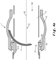
- the figure 3a is a schematic sectional view in the median plane 25, and illustrating a valve 1 according to an embodiment of the invention in a closed position 101.
- the figure 3b is a schematic sectional view in a plane comprising the axis of symmetry 26 and perpendicular to the median plane 25, and illustrating a valve 1 according to an embodiment of the invention in a closed position 101.
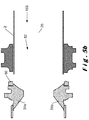
- the figures 4a and 4b correspond to a position 102 intermediate between the closed position 101 and an open position 103.
- the figures 5a and 5b correspond to the open position 103.
- These figures illustrate a seal 92 making it possible to avoid leaks between the rotary shutter 5 and the obstacle 3 and a guide 91 making it possible to guide the rotation of the rotary shutter 5.
- the obstacle 3 is preferably located upstream of the axis of rotation 51 relative to the movement of fluid.
- the part of the rotary shutter 5 which is in the channel 2, in particular the recess 52, is preferably symmetrical with respect to the median plane 25.
- the recess 52 In the closed position 101, the recess 52 is preferably open downstream and the rotary shutter 5 has a wall 53 directed essentially upstream.
- the arrow 55 represents the direction of rotation of the rotary shutter 5 between the closed position 101 and the open position 103.
- the rotary shutter 5 preferably rotates 90 ° around the axis of rotation 51 between the closed position. 101 and the open position 103.
- the third obstacle element 31c forms a screen for the part of the rotary shutter 5 which is in the median plane 25, and which may be called the median part of the rotary shutter 5.
- the first 31a and the second 31b obstacle elements form a screen for the parts of the rotary shutter 5 which are on either side of the recess 52 along the axis 51, and which can be called upper parts and lower part of the rotary shutter 5.
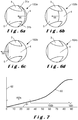
- the figure 6 is an elevational view illustrating the evolution of the position of the rotary shutter 5 as it moves through its rotary stroke.
- the arrow 56 is the direction of enlargement of the opening 4. This direction is parallel to the median plane 25.
- the protrusions 32a, 32b point both in a direction partially opposite to this direction of enlargement of the opening 4 and towards the median plane 25.
- the figure 6a corresponds to a first part 102a of the rotary stroke, which is the rotary stroke part between the closed position and the meeting of the opening 4 with the first and second obstacle elements 31a, 31b.
- the obstruction device 10 is preferably designed not to obstruct the opening 4 during the first part 102a of the rotary stroke in order to have a flow rate which increases rapidly as a function of the angle of rotation.
- the protrusions 32a, 32b are the parts of the first and second obstacle elements 31a, 31b which are first encountered by the opening 4.
- the figures 6b and 6c correspond to a second part 102b of the rotary stroke, which is the rotary stroke part between the meeting of the opening 4 with the first and second obstacle elements 31a, 31b and the meeting of the opening 4 with the third element obstacle 31c.
- a first object of the present invention is to obtain a slope of the flow rate curve 62 versus angle 61 in the first part 102a of the stroke. rotary which is high, in the second portion 102b of the rotary stroke which is low in order to allow regulation with high precision.
- a second object is to have at the end of the third part 102c of the rotary stroke the greatest flow rate value 62.
- the figure 6d corresponds to a third part 102c of the rotary stroke, which is the rotary stroke part after meeting the opening 4 with the third obstacle member 31c.
- the flow rate then hardly depends on the angle because almost all of the rotary shutter 5 is behind the obstacle 3.
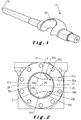
- the invention relates in particular to a ball valve 1 for regulating a flow of fluid through a channel 2.
- the valve 1 comprises a rotary shutter 5 and an obstacle 3 located directly upstream of the shutter. rotary 5.
- the combined obstructions due to the rotary shutter 5 and the obstacle 3 reduce the possible passage for the fluid to an opening 4 whose area depends on the angle of rotation of the rotary shutter 5.
- the obstacle 3 comprises a first 31a and a second 31b obstacle elements located on either side of a median plane 25 perpendicular to the axis of rotation 51 of the rotary shutter 5.
- the first 31a and second 31b elements d The obstacle each have a protrusion 32a, 32b which points to the part 21 of channel 2 which is opened first when opening the valve 1.
Landscapes
- Engineering & Computer Science (AREA)
- General Engineering & Computer Science (AREA)
- Mechanical Engineering (AREA)
- Taps Or Cocks (AREA)
- Pharmaceuticals Containing Other Organic And Inorganic Compounds (AREA)
Claims (13)
- Absperrorgan (1), umfassend einen Kanal (2) und eine Absperrvorrichtung (10), wobei die Absperrvorrichtung (10) umfasst:• ein Hindernis (3), das den Kanal (2) teilweise versperrt, wobei das Hindernis (3) ein erstes (31a) und ein zweites (31b) Hinderniselement umfasst, die mechanisch mit einer Innenwand des Kanals (2) verbunden sind, und• einen Drehverschluss (5), der zur Drehung um eine Drehachse (51) angeordnet ist; wobei das Absperrorgan (1) angeordnet ist, um:- eine geschlossene Position (101) aufzuweisen, in der die Absperrvorrichtung (10) den Kanal (2) maximal absperrt, und- eine offene Position (103) aufzuweisen, in der die Absperrvorrichtung (10) den Kanal (2) minimal absperrt;wobei der Kanal (2) einen ersten Teil (21) umfasst, welcher der Teil des Kanals (2) ist, der bei einer Drehbewegung des Drehverschlusses (5) zum Durchgang zwischen der geschlossenen Position (101) und der offenen Position (103) des Absperrorgans (1) zunächst durch den Drehverschluss (5) nicht blockiert wird, wobei das erste (31a) und das zweite (31b) Hinderniselement einen Vorsprung (32a, 32b) aufweisen, der dem ersten Teil (21) des Kanals zugewandt ist, dadurch gekennzeichnet, dass das Hindernis (3) ein drittes Hinderniselement (31c) umfasst, das mechanisch mit einer Innenwand des Kanals (2) gekoppelt ist, das dem Kanal (2) in Bezug auf den ersten Teil (21) des Kanals (2) gegenüberliegt und eine zur Drehachse (51) parallele Oberfläche (32c) umfasst.
- Absperrorgan (1) nach Anspruch 1, wobei das Hindernis (3) symmetrisch in Bezug auf eine zur Drehachse (51) senkrechte Mittelebene (25) ist, und die den Kanal (2) in zwei symmetrische Teile trennt.
- Absperrorgan (1) nach einem der vorstehenden Ansprüche, wobei das erste (31a) und das zweite (31b) Hindernis jeweils eine erste Oberfläche (33a, 33b) umfassen, die zu der Innenoberfläche des Kanals (2) ausgerichtet ist.
- Absperrorgan (1) nach dem vorstehenden Anspruch, wobei die ersten Oberflächen (33a, 33b) des ersten (31a) und zweiten (31b) Hinderniselements gekrümmt und konvex sind.
- Absperrorgan (1) nach einem der vorstehenden Ansprüche, wobei das erste (31a) und das zweite (31b) Hinderniselement jeweils eine zweite Oberfläche (34a, 34b) umfassen, die zu einer Symmetrieachse (26) des Kanals (2) ausgerichtet ist.
- Absperrorgan (1) nach dem vorstehenden Anspruch, wobei die zweiten Oberflächen (34a, 34b) des ersten (31a) und zweiten (31b) Hinderniselements gekrümmt und konvex sind.
- Absperrorgan (1) nach einem der vorstehenden Ansprüche, wobei das Hindernis (3) in Bezug auf die Fluidbewegung stromaufwärts von der Drehachse (51) angeordnet ist.
- Absperrorgan (1) nach einem der vorstehenden Ansprüche, das so angeordnet ist, dass der Drehverschluss (5) in der geschlossenen Position (101) teilweise zwischen dem ersten (31a) und dem zweiten (31b) Hinderniselement in Eingriff ist.
- Absperrorgan (1) nach einem der vorstehenden Ansprüche, wobei die Drehachse (51) in Bezug auf eine Symmetrieachse (26) des Kanals (2) zum ersten Teil (21) des Kanals hin versetzt ist.
- Absperrorgan (1) nach einem der vorstehenden Ansprüche, wobei das dritte Hinderniselement (31c) von dem ersten (31a) und zweiten (31b) Hinderniselement getrennt ist.
- Absperrorgan (1) nach einem der vorstehenden Ansprüche, umfassend höchstens drei Hinderniselemente (31a, 31b, 31c).
- Absperrorgan (1) nach einem der vorstehenden Ansprüche, wobei die Fläche des Hindernisses (3) 10 % bis 40 % der Fläche eines Abschnitts des Kanals (2), bevorzugt 20 % bis 30 % der Fläche eines Abschnitts des Kanals (2), beträgt.
- Verwendung eines Absperrorgans (1) nach einem der vorstehenden Ansprüche, umfassend eine Drehung des Drehverschlusses (5) um die Drehachse (51).
Applications Claiming Priority (1)
| Application Number | Priority Date | Filing Date | Title |
|---|---|---|---|
| BE20185948A BE1026921B1 (fr) | 2018-12-26 | 2018-12-26 | Vanne |
Publications (2)
| Publication Number | Publication Date |
|---|---|
| EP3674586A1 EP3674586A1 (de) | 2020-07-01 |
| EP3674586B1 true EP3674586B1 (de) | 2021-06-23 |
Family
ID=65234310
Family Applications (1)
| Application Number | Title | Priority Date | Filing Date |
|---|---|---|---|
| EP19216932.4A Active EP3674586B1 (de) | 2018-12-26 | 2019-12-17 | Ventil |
Country Status (2)
| Country | Link |
|---|---|
| EP (1) | EP3674586B1 (de) |
| BE (1) | BE1026921B1 (de) |
Family Cites Families (6)
| Publication number | Priority date | Publication date | Assignee | Title |
|---|---|---|---|---|
| GB2115112A (en) * | 1982-02-01 | 1983-09-01 | Worcester Controls Corp | Rotary ball valves |
| US5937890A (en) * | 1998-01-09 | 1999-08-17 | Griswold Controls, Inc. | Insert for flow throttling ball valves |
| US7111643B2 (en) * | 2005-01-26 | 2006-09-26 | Invensys Building Systems, Inc. | Flow characterization in a flowpath |
| US8413684B2 (en) * | 2009-09-16 | 2013-04-09 | Schneider Electric Buildings, Llc | Ball valve with anti-rotational pressure plate |
| US20140209828A1 (en) * | 2013-01-31 | 2014-07-31 | Belimo Holding Ag | Flow characterizing device and ball valve with such a flow characterizing device |
| SE541043C2 (en) * | 2015-08-28 | 2019-03-19 | Ab Somas Ventiler | A valve, a valve set and a method for modifying a valve |
-
2018
- 2018-12-26 BE BE20185948A patent/BE1026921B1/fr active IP Right Grant
-
2019
- 2019-12-17 EP EP19216932.4A patent/EP3674586B1/de active Active
Also Published As
| Publication number | Publication date |
|---|---|
| EP3674586A1 (de) | 2020-07-01 |
| BE1026921A1 (fr) | 2020-07-22 |
| BE1026921B1 (fr) | 2020-07-28 |
Similar Documents
| Publication | Publication Date | Title |
|---|---|---|
| LU83496A1 (fr) | Robinet a papillon | |
| EP3123059B1 (de) | Getriebeanordnung mit einem getriebeelement und einem ölverteilungssystem | |
| EP2850298B1 (de) | Ventil zum steuerung eines flüssigkeitsstroms mit einer drehverschlussvorrichtung | |
| WO2008122712A2 (fr) | Element de raccord a soupape d'obturation | |
| EP0023172B1 (de) | Ventil mit Schwingungsunterdrückung | |
| EP2880367B1 (de) | Triebwerke-brennkammer mit kugelförmigem einlass / auslassventil | |
| EP2984374B1 (de) | Ventil, insbesondere motorsteuerventil, mit einem dosierschieber und einem ablenkschieber | |
| EP3674586B1 (de) | Ventil | |
| EP2984377B1 (de) | Ventil, insbesondere motorsteuerventil, mit einem dosierschieber und einem ablenkschieber | |
| CH619522A5 (de) | ||
| EP0268521B1 (de) | Schleusenventil | |
| EP1283964B1 (de) | Hahn mit sekundärer öffnung | |
| CA2921915C (fr) | Arriere corps de turboreacteur comportant une tuyere equipee d'un systeme d'inversion de poussee qui integre une couronne de chevrons antibruit | |
| EP2273126B1 (de) | Rückschlagventil für automatische Rückführung | |
| EP4305328A1 (de) | Expansionsventil mit einem beweglichen schieber | |
| EP1938010B1 (de) | Wasserhahn mit kugelförmigem drehverschluss | |
| EP2811208A1 (de) | Absperr- und Regulierhahn | |
| FR3004777A1 (fr) | Dispositif de vanne a papillon incline. | |
| FR2996259A1 (fr) | Vanne de controle moteur dotee d'un volet simplifie | |
| EP4088015A1 (de) | Düse mit variablem auslassquerschnitt für raketenmotor und raketenmotor mit einer solchen düse | |
| FR2858840A1 (fr) | Dispositifs de fermeture et d'etancheite a parallelogramme deformable et profil d'ecoulement optimise | |
| WO2011141641A1 (fr) | Robinet a joint metallique | |
| CH494356A (fr) | Vanne à obturateur à deux opercules | |
| WO2016059325A1 (fr) | Vanne comportant un conduit pour conduire un fluide et un joint dispose dans le conduit | |
| FR2516627A1 (fr) | Robinet a cle, notamment robinet a boisseau |
Legal Events
| Date | Code | Title | Description |
|---|---|---|---|
| PUAI | Public reference made under article 153(3) epc to a published international application that has entered the european phase |
Free format text: ORIGINAL CODE: 0009012 |
|
| STAA | Information on the status of an ep patent application or granted ep patent |
Free format text: STATUS: THE APPLICATION HAS BEEN PUBLISHED |
|
| AK | Designated contracting states |
Kind code of ref document: A1 Designated state(s): AL AT BE BG CH CY CZ DE DK EE ES FI FR GB GR HR HU IE IS IT LI LT LU LV MC MK MT NL NO PL PT RO RS SE SI SK SM TR |
|
| AX | Request for extension of the european patent |
Extension state: BA ME |
|
| STAA | Information on the status of an ep patent application or granted ep patent |
Free format text: STATUS: REQUEST FOR EXAMINATION WAS MADE |
|
| 17P | Request for examination filed |
Effective date: 20201210 |
|
| RBV | Designated contracting states (corrected) |
Designated state(s): AL AT BE BG CH CY CZ DE DK EE ES FI FR GB GR HR HU IE IS IT LI LT LU LV MC MK MT NL NO PL PT RO RS SE SI SK SM TR |
|
| GRAP | Despatch of communication of intention to grant a patent |
Free format text: ORIGINAL CODE: EPIDOSNIGR1 |
|
| STAA | Information on the status of an ep patent application or granted ep patent |
Free format text: STATUS: GRANT OF PATENT IS INTENDED |
|
| INTG | Intention to grant announced |
Effective date: 20210210 |
|
| GRAS | Grant fee paid |
Free format text: ORIGINAL CODE: EPIDOSNIGR3 |
|
| GRAA | (expected) grant |
Free format text: ORIGINAL CODE: 0009210 |
|
| STAA | Information on the status of an ep patent application or granted ep patent |
Free format text: STATUS: THE PATENT HAS BEEN GRANTED |
|
| AK | Designated contracting states |
Kind code of ref document: B1 Designated state(s): AL AT BE BG CH CY CZ DE DK EE ES FI FR GB GR HR HU IE IS IT LI LT LU LV MC MK MT NL NO PL PT RO RS SE SI SK SM TR |
|
| REG | Reference to a national code |
Ref country code: GB Ref legal event code: FG4D Free format text: NOT ENGLISH |
|
| REG | Reference to a national code |
Ref country code: CH Ref legal event code: EP |
|
| REG | Reference to a national code |
Ref country code: DE Ref legal event code: R096 Ref document number: 602019005591 Country of ref document: DE Ref country code: AT Ref legal event code: REF Ref document number: 1404586 Country of ref document: AT Kind code of ref document: T Effective date: 20210715 |
|
| REG | Reference to a national code |
Ref country code: IE Ref legal event code: FG4D Free format text: LANGUAGE OF EP DOCUMENT: FRENCH |
|
| REG | Reference to a national code |
Ref country code: LT Ref legal event code: MG9D |
|
| PG25 | Lapsed in a contracting state [announced via postgrant information from national office to epo] |
Ref country code: FI Free format text: LAPSE BECAUSE OF FAILURE TO SUBMIT A TRANSLATION OF THE DESCRIPTION OR TO PAY THE FEE WITHIN THE PRESCRIBED TIME-LIMIT Effective date: 20210623 Ref country code: HR Free format text: LAPSE BECAUSE OF FAILURE TO SUBMIT A TRANSLATION OF THE DESCRIPTION OR TO PAY THE FEE WITHIN THE PRESCRIBED TIME-LIMIT Effective date: 20210623 Ref country code: LT Free format text: LAPSE BECAUSE OF FAILURE TO SUBMIT A TRANSLATION OF THE DESCRIPTION OR TO PAY THE FEE WITHIN THE PRESCRIBED TIME-LIMIT Effective date: 20210623 Ref country code: BG Free format text: LAPSE BECAUSE OF FAILURE TO SUBMIT A TRANSLATION OF THE DESCRIPTION OR TO PAY THE FEE WITHIN THE PRESCRIBED TIME-LIMIT Effective date: 20210923 |
|
| REG | Reference to a national code |
Ref country code: AT Ref legal event code: MK05 Ref document number: 1404586 Country of ref document: AT Kind code of ref document: T Effective date: 20210623 |
|
| PG25 | Lapsed in a contracting state [announced via postgrant information from national office to epo] |
Ref country code: RS Free format text: LAPSE BECAUSE OF FAILURE TO SUBMIT A TRANSLATION OF THE DESCRIPTION OR TO PAY THE FEE WITHIN THE PRESCRIBED TIME-LIMIT Effective date: 20210623 Ref country code: SE Free format text: LAPSE BECAUSE OF FAILURE TO SUBMIT A TRANSLATION OF THE DESCRIPTION OR TO PAY THE FEE WITHIN THE PRESCRIBED TIME-LIMIT Effective date: 20210623 Ref country code: NO Free format text: LAPSE BECAUSE OF FAILURE TO SUBMIT A TRANSLATION OF THE DESCRIPTION OR TO PAY THE FEE WITHIN THE PRESCRIBED TIME-LIMIT Effective date: 20210923 Ref country code: LV Free format text: LAPSE BECAUSE OF FAILURE TO SUBMIT A TRANSLATION OF THE DESCRIPTION OR TO PAY THE FEE WITHIN THE PRESCRIBED TIME-LIMIT Effective date: 20210623 Ref country code: GR Free format text: LAPSE BECAUSE OF FAILURE TO SUBMIT A TRANSLATION OF THE DESCRIPTION OR TO PAY THE FEE WITHIN THE PRESCRIBED TIME-LIMIT Effective date: 20210924 |
|
| REG | Reference to a national code |
Ref country code: NL Ref legal event code: MP Effective date: 20210623 |
|
| PG25 | Lapsed in a contracting state [announced via postgrant information from national office to epo] |
Ref country code: AT Free format text: LAPSE BECAUSE OF FAILURE TO SUBMIT A TRANSLATION OF THE DESCRIPTION OR TO PAY THE FEE WITHIN THE PRESCRIBED TIME-LIMIT Effective date: 20210623 Ref country code: CZ Free format text: LAPSE BECAUSE OF FAILURE TO SUBMIT A TRANSLATION OF THE DESCRIPTION OR TO PAY THE FEE WITHIN THE PRESCRIBED TIME-LIMIT Effective date: 20210623 Ref country code: NL Free format text: LAPSE BECAUSE OF FAILURE TO SUBMIT A TRANSLATION OF THE DESCRIPTION OR TO PAY THE FEE WITHIN THE PRESCRIBED TIME-LIMIT Effective date: 20210623 Ref country code: RO Free format text: LAPSE BECAUSE OF FAILURE TO SUBMIT A TRANSLATION OF THE DESCRIPTION OR TO PAY THE FEE WITHIN THE PRESCRIBED TIME-LIMIT Effective date: 20210623 Ref country code: PT Free format text: LAPSE BECAUSE OF FAILURE TO SUBMIT A TRANSLATION OF THE DESCRIPTION OR TO PAY THE FEE WITHIN THE PRESCRIBED TIME-LIMIT Effective date: 20211025 Ref country code: SM Free format text: LAPSE BECAUSE OF FAILURE TO SUBMIT A TRANSLATION OF THE DESCRIPTION OR TO PAY THE FEE WITHIN THE PRESCRIBED TIME-LIMIT Effective date: 20210623 Ref country code: SK Free format text: LAPSE BECAUSE OF FAILURE TO SUBMIT A TRANSLATION OF THE DESCRIPTION OR TO PAY THE FEE WITHIN THE PRESCRIBED TIME-LIMIT Effective date: 20210623 Ref country code: ES Free format text: LAPSE BECAUSE OF FAILURE TO SUBMIT A TRANSLATION OF THE DESCRIPTION OR TO PAY THE FEE WITHIN THE PRESCRIBED TIME-LIMIT Effective date: 20210623 Ref country code: EE Free format text: LAPSE BECAUSE OF FAILURE TO SUBMIT A TRANSLATION OF THE DESCRIPTION OR TO PAY THE FEE WITHIN THE PRESCRIBED TIME-LIMIT Effective date: 20210623 |
|
| PG25 | Lapsed in a contracting state [announced via postgrant information from national office to epo] |
Ref country code: PL Free format text: LAPSE BECAUSE OF FAILURE TO SUBMIT A TRANSLATION OF THE DESCRIPTION OR TO PAY THE FEE WITHIN THE PRESCRIBED TIME-LIMIT Effective date: 20210623 |
|
| REG | Reference to a national code |
Ref country code: DE Ref legal event code: R097 Ref document number: 602019005591 Country of ref document: DE |
|
| PG25 | Lapsed in a contracting state [announced via postgrant information from national office to epo] |
Ref country code: DK Free format text: LAPSE BECAUSE OF FAILURE TO SUBMIT A TRANSLATION OF THE DESCRIPTION OR TO PAY THE FEE WITHIN THE PRESCRIBED TIME-LIMIT Effective date: 20210623 |
|
| PLBE | No opposition filed within time limit |
Free format text: ORIGINAL CODE: 0009261 |
|
| STAA | Information on the status of an ep patent application or granted ep patent |
Free format text: STATUS: NO OPPOSITION FILED WITHIN TIME LIMIT |
|
| 26N | No opposition filed |
Effective date: 20220324 |
|
| PG25 | Lapsed in a contracting state [announced via postgrant information from national office to epo] |
Ref country code: AL Free format text: LAPSE BECAUSE OF FAILURE TO SUBMIT A TRANSLATION OF THE DESCRIPTION OR TO PAY THE FEE WITHIN THE PRESCRIBED TIME-LIMIT Effective date: 20210623 |
|
| PG25 | Lapsed in a contracting state [announced via postgrant information from national office to epo] |
Ref country code: MC Free format text: LAPSE BECAUSE OF FAILURE TO SUBMIT A TRANSLATION OF THE DESCRIPTION OR TO PAY THE FEE WITHIN THE PRESCRIBED TIME-LIMIT Effective date: 20210623 |
|
| PG25 | Lapsed in a contracting state [announced via postgrant information from national office to epo] |
Ref country code: LU Free format text: LAPSE BECAUSE OF NON-PAYMENT OF DUE FEES Effective date: 20211217 Ref country code: IE Free format text: LAPSE BECAUSE OF NON-PAYMENT OF DUE FEES Effective date: 20211217 |
|
| PG25 | Lapsed in a contracting state [announced via postgrant information from national office to epo] |
Ref country code: CY Free format text: LAPSE BECAUSE OF FAILURE TO SUBMIT A TRANSLATION OF THE DESCRIPTION OR TO PAY THE FEE WITHIN THE PRESCRIBED TIME-LIMIT Effective date: 20210623 |
|
| PG25 | Lapsed in a contracting state [announced via postgrant information from national office to epo] |
Ref country code: HU Free format text: LAPSE BECAUSE OF FAILURE TO SUBMIT A TRANSLATION OF THE DESCRIPTION OR TO PAY THE FEE WITHIN THE PRESCRIBED TIME-LIMIT; INVALID AB INITIO Effective date: 20191217 |
|
| REG | Reference to a national code |
Ref country code: CH Ref legal event code: PL |
|
| PG25 | Lapsed in a contracting state [announced via postgrant information from national office to epo] |
Ref country code: LI Free format text: LAPSE BECAUSE OF NON-PAYMENT OF DUE FEES Effective date: 20221231 Ref country code: CH Free format text: LAPSE BECAUSE OF NON-PAYMENT OF DUE FEES Effective date: 20221231 |
|
| PG25 | Lapsed in a contracting state [announced via postgrant information from national office to epo] |
Ref country code: MK Free format text: LAPSE BECAUSE OF FAILURE TO SUBMIT A TRANSLATION OF THE DESCRIPTION OR TO PAY THE FEE WITHIN THE PRESCRIBED TIME-LIMIT Effective date: 20210623 |
|
| PG25 | Lapsed in a contracting state [announced via postgrant information from national office to epo] |
Ref country code: MT Free format text: LAPSE BECAUSE OF FAILURE TO SUBMIT A TRANSLATION OF THE DESCRIPTION OR TO PAY THE FEE WITHIN THE PRESCRIBED TIME-LIMIT Effective date: 20210623 |
|
| PG25 | Lapsed in a contracting state [announced via postgrant information from national office to epo] |
Ref country code: TR Free format text: LAPSE BECAUSE OF FAILURE TO SUBMIT A TRANSLATION OF THE DESCRIPTION OR TO PAY THE FEE WITHIN THE PRESCRIBED TIME-LIMIT Effective date: 20210623 |
|
| PGFP | Annual fee paid to national office [announced via postgrant information from national office to epo] |
Ref country code: GB Payment date: 20251229 Year of fee payment: 7 |
|
| PGFP | Annual fee paid to national office [announced via postgrant information from national office to epo] |
Ref country code: FR Payment date: 20251222 Year of fee payment: 7 |
|
| PGFP | Annual fee paid to national office [announced via postgrant information from national office to epo] |
Ref country code: BE Payment date: 20251224 Year of fee payment: 7 |
|
| PGFP | Annual fee paid to national office [announced via postgrant information from national office to epo] |
Ref country code: DE Payment date: 20251222 Year of fee payment: 7 |
|
| PGFP | Annual fee paid to national office [announced via postgrant information from national office to epo] |
Ref country code: IT Payment date: 20251231 Year of fee payment: 7 |