EP3674623B1 - Climatiseur encastré au plafond - Google Patents
Climatiseur encastré au plafond Download PDFInfo
- Publication number
- EP3674623B1 EP3674623B1 EP17922383.9A EP17922383A EP3674623B1 EP 3674623 B1 EP3674623 B1 EP 3674623B1 EP 17922383 A EP17922383 A EP 17922383A EP 3674623 B1 EP3674623 B1 EP 3674623B1
- Authority
- EP
- European Patent Office
- Prior art keywords
- locking element
- suction grille
- decorative panel
- spring
- conditioning apparatus
- Prior art date
- Legal status (The legal status is an assumption and is not a legal conclusion. Google has not performed a legal analysis and makes no representation as to the accuracy of the status listed.)
- Active
Links
Images


Classifications
-
- F—MECHANICAL ENGINEERING; LIGHTING; HEATING; WEAPONS; BLASTING
- F24—HEATING; RANGES; VENTILATING
- F24F—AIR-CONDITIONING; AIR-HUMIDIFICATION; VENTILATION; USE OF AIR CURRENTS FOR SCREENING
- F24F1/00—Room units for air-conditioning, e.g. separate or self-contained units or units receiving primary air from a central station
- F24F1/0007—Indoor units, e.g. fan coil units
- F24F1/0043—Indoor units, e.g. fan coil units characterised by mounting arrangements
- F24F1/0047—Indoor units, e.g. fan coil units characterised by mounting arrangements mounted in the ceiling or at the ceiling
-
- F—MECHANICAL ENGINEERING; LIGHTING; HEATING; WEAPONS; BLASTING
- F24—HEATING; RANGES; VENTILATING
- F24F—AIR-CONDITIONING; AIR-HUMIDIFICATION; VENTILATION; USE OF AIR CURRENTS FOR SCREENING
- F24F13/00—Details common to, or for air-conditioning, air-humidification, ventilation or use of air currents for screening
- F24F13/08—Air-flow control members, e.g. louvres, grilles, flaps or guide plates
- F24F13/082—Grilles, registers or guards
- F24F13/084—Grilles, registers or guards with mounting arrangements, e.g. snap fasteners for mounting to the wall or duct
-
- F—MECHANICAL ENGINEERING; LIGHTING; HEATING; WEAPONS; BLASTING
- F24—HEATING; RANGES; VENTILATING
- F24F—AIR-CONDITIONING; AIR-HUMIDIFICATION; VENTILATION; USE OF AIR CURRENTS FOR SCREENING
- F24F13/00—Details common to, or for air-conditioning, air-humidification, ventilation or use of air currents for screening
- F24F13/20—Casings or covers
-
- F—MECHANICAL ENGINEERING; LIGHTING; HEATING; WEAPONS; BLASTING
- F24—HEATING; RANGES; VENTILATING
- F24F—AIR-CONDITIONING; AIR-HUMIDIFICATION; VENTILATION; USE OF AIR CURRENTS FOR SCREENING
- F24F13/00—Details common to, or for air-conditioning, air-humidification, ventilation or use of air currents for screening
- F24F13/30—Arrangement or mounting of heat-exchangers
-
- F—MECHANICAL ENGINEERING; LIGHTING; HEATING; WEAPONS; BLASTING
- F24—HEATING; RANGES; VENTILATING
- F24F—AIR-CONDITIONING; AIR-HUMIDIFICATION; VENTILATION; USE OF AIR CURRENTS FOR SCREENING
- F24F13/00—Details common to, or for air-conditioning, air-humidification, ventilation or use of air currents for screening
- F24F13/20—Casings or covers
- F24F2013/205—Mounting a ventilator fan therein
Definitions
- the body 10 is formed of a cuboid metal plate with an opening port at the bottom.
- the suction grille 14 has a rectangular shape along a longitudinal direction of the body 10.
- the suction grille 14 includes, at its respective ends in a transverse direction, air inlets 16 each composed of multiple grilles and formed lengthwise.
- the suction grille 14 is formed by resin molding.
- the decorative panel 13 is fixed to the body 10.
- the decorative panel 13 is formed with an air outlet 17 on one side of the air inlets 16.
- a pivotable wind vane for changing air blow directions is attached to the air outlet 17.
- the locking part 32 is a protrusion protruding upward further than a distal end of the guide part 33 of the locking element 30.
- the guide part 33 protrudes upward from the top face at each end of the locking element 30.
- the guide part 33 has an inclined surface.
- the long plate spring 31a and the short plate spring 31b extend opposite to each other and at right angles from respective ends of the locking element 30 perpendicular to its sliding direction.
- the operation part 35 extends downward from a rear part of the locking element 30.
- the slide parts receive a screw 40.
- the long hole extends lengthwise in the front-back direction of the locking element 30 and allows for insertion of the screw 40.
- the locking element 30 resides on the air inlet 15 side of the suction grille 14 and rests on a support frame extending to the inside of the air inlet 15 from the grille located at the end of the air inlet 15.
- the support frame is formed with a screw hole to receive the above-described screw 40 and supports the locking element 30 so that the locking element 30 can slide in the longitudinal direction of the long hole.
- Each of the long plate spring 31a and the short plate spring 31b extending from the respective sides of the locking element 30 is sandwiched between a main rib 15a and an auxiliary rib 15b provided on two respective grilles on the end side of the plural grilles forming the air inlet 16.
- Each of the long plate spring 31a and the short plate spring 31b is held at two points by these ribs 15a, 15b. This can correct any deformation or variation of the long and short plate springs 31a, 31b in an advancing direction 50 or a retracting direction 60 that may occur during molding of the long and short plate springs 31a, 31b.
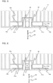
- Fig. 8 is a sectional view showing a positional relationship between the locking element and the decorative panel when the suction grille of Fig. 3 is lifted close to the decorative panel.
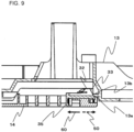
- Fig. 9 is a sectional view showing a positional relationship between the locking element and the decorative panel when the suction grille of Fig. 8 is about to be closed into the decorative panel.
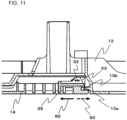
- Fig. 10 is a sectional view showing a positional relationship between the locking element and the decorative panel when the suction grille of Fig. 9 has been closed into the decorative panel.
- Fig. 11 is a sectional view showing a positional relationship between the locking element and the decorative panel when the locking element of Fig. 10 is retracted.
- each of the long and short plate springs 31a, 31b on the respective sides of the locking element 30 bends in the retracting direction 60 around the main rib 15a and the auxiliary rib 15b as fulcrums against the elastic force.
- the locking element 30 advances in the direction (advancing direction 50) indicated by the dashed arrow by the elastic force of the long and short plate springs 31a, 31b, as shown in Fig. 10 , resulting in the suction grille-side locking part 32 of the locking element 30 being locked into a decorative panel-side fixed locking part 13b.
- the suction panel 14 closes the opening port of the body 10.
- the long and short plate springs 31a, 31b extending from the respective sides of the locking element 30 have different spring lengths and are also held by the main rib 15a and the auxiliary rib 15b at different distances from the locking part 32. This can, by leveraging the property that the bending spring force against the elastic force varies depending on the length of the spring, absorb any engagement displacement of the locking element 30 on the suction grille 14 in the transverse direction, improving operability.
Landscapes
- Engineering & Computer Science (AREA)
- Chemical & Material Sciences (AREA)
- Combustion & Propulsion (AREA)
- Mechanical Engineering (AREA)
- General Engineering & Computer Science (AREA)
- Air Filters, Heat-Exchange Apparatuses, And Housings Of Air-Conditioning Units (AREA)
Claims (5)
- Appareil de climatisation encastré au plafond, comprenant :un corps (10) contenant un échangeur de chaleur (11) et un ventilateur (12) et incluant un orifice d'ouverture au niveau d'une partie inférieure ;un panneau décoratif (13) disposé en dessous du corps (10), le panneau décoratif (13) étant configuré pour recouvrir une périphérie de l'orifice d'ouverture du corps (10) ; etune grille d'aspiration (14) incluant, sur un bord de celle-ci, un arbre rotatif (20) qui peut être fixé au panneau décoratif (13), la grille d'aspiration (14) étant configurée pour recouvrir l'orifice d'ouverture du corps (10) de manière à permettre l'ouverture de l'orifice d'ouverture, dans lequella grille d'aspiration (14) inclut :un élément de verrouillage (30) monté sur un côté arrière de la grille d'aspiration (14) de manière à pouvoir coulisser et configuré pour être verrouillé avec le panneau décoratif (13) ;des ressorts plats (31a, 31b) sur des côtés respectifs de l'élément de verrouillage (30) perpendiculaires à une direction de coulissement de l'élément de verrouillage (30), les ressorts plats (31a, 31b) s'étendant verticalement dans des directions opposées l'une à l'autre ; etdes supports de ressort (15a, 15b) prévus sur la grille d'aspiration (14) et configurés pour supporter les deux faces d'extrémité des ressorts plats respectifs (31a, 31b) dans différentes positions,les ressorts plats (31a, 31b) de l'élément de verrouillage (30) incluent un ressort plat long (31a) et un ressort plat court (31b) présentant des longueurs différentes, etle ressort plat long (31a) et le ressort plat court (31b) sont placés de telle sorte que le ressort plat long (31a) est mis en prise en premier lorsque la grille d'aspiration (14) est fixée au panneau décoratif (13).
- Appareil de climatisation encastré au plafond selon la revendication 1, dans lequel une distance entre l'élément de verrouillage (30) et un certain des supports de ressort (15a, 15b) maintenant le ressort plat long (31a) s'étendant à partir de l'élément de verrouillage (30) est supérieure à une distance entre l'élément de verrouillage (30) et un autre des supports de ressort (15a, 15b) maintenant le ressort plat court (31b).
- Appareil de climatisation encastré au plafond selon la revendication 1 ou 2, dans lequel l'élément de verrouillage (30) monté sur la grille d'aspiration (14) est placé sur chacun des bords de la grille d'aspiration (14) qui s'étendent à angle droit à partir du bord de la grille d'aspiration (14) fixée au panneau décoratif (13) via l'arbre rotatif (20).
- Appareil de climatisation encastré au plafond selon l'une quelconque des revendications 1 à 3, dans lequel lorsque l'élément de verrouillage (30) coulisse dans une direction de rétraction à l'écart du panneau décoratif (13), les ressorts plats (31a, 31b) activent l'élément de verrouillage (30) dans une direction de mise en prise avec le panneau décoratif (13) en utilisant comme points d'appui les supports de ressort respectifs (15a, 15b) maintenant les ressorts plats respectifs (31a, 31b) dans les différentes positions.
- Appareil de climatisation encastré au plafond selon l'une quelconque des revendications 1 à 4, dans lequelle ventilateur (12) comprend un ventilateur à flux transversal, et l'échangeur de chaleur (11) est en forme de V et placé entre le ventilateur (12) et la grille d'aspiration (14),une direction longitudinale de la grille d'aspiration (14) de forme rectangulaire coïncide avec une direction axiale du ventilateur à flux transversal, et l'élément de verrouillage (30) est placé de chaque côté de la grille d'aspiration (14) dans une direction transversale.
Applications Claiming Priority (1)
| Application Number | Priority Date | Filing Date | Title |
|---|---|---|---|
| PCT/JP2017/029738 WO2019038798A1 (fr) | 2017-08-21 | 2017-08-21 | Climatiseur encastré au plafond |
Publications (3)
| Publication Number | Publication Date |
|---|---|
| EP3674623A1 EP3674623A1 (fr) | 2020-07-01 |
| EP3674623A4 EP3674623A4 (fr) | 2020-08-19 |
| EP3674623B1 true EP3674623B1 (fr) | 2025-04-16 |
Family
ID=65439975
Family Applications (1)
| Application Number | Title | Priority Date | Filing Date |
|---|---|---|---|
| EP17922383.9A Active EP3674623B1 (fr) | 2017-08-21 | 2017-08-21 | Climatiseur encastré au plafond |
Country Status (5)
| Country | Link |
|---|---|
| US (1) | US11614240B2 (fr) |
| EP (1) | EP3674623B1 (fr) |
| JP (1) | JP6758511B2 (fr) |
| CN (1) | CN209326052U (fr) |
| WO (1) | WO2019038798A1 (fr) |
Families Citing this family (6)
| Publication number | Priority date | Publication date | Assignee | Title |
|---|---|---|---|---|
| US12442544B2 (en) * | 2019-09-27 | 2025-10-14 | Air Innovations, Llc | Ceiling mounted evaporator blower |
| US11536467B2 (en) * | 2019-09-27 | 2022-12-27 | Air Innovations, Inc. | Ceiling mounted evaporator blower with swing up hinged installation |
| KR102467323B1 (ko) * | 2020-08-07 | 2022-11-14 | 엘지전자 주식회사 | 공기청정기 |
| CN112623229B (zh) * | 2020-12-29 | 2023-03-14 | 中国航空工业集团公司西安飞机设计研究所 | 一种飞机可调节式空调供气口装置 |
| CN112944654A (zh) * | 2021-03-22 | 2021-06-11 | 珠海格力电器股份有限公司 | 一种滑动锁紧组件、面板装置及空调器 |
| JP1709599S (ja) * | 2021-03-31 | 2022-03-11 | エアーコンディショナー |
Family Cites Families (15)
| Publication number | Priority date | Publication date | Assignee | Title |
|---|---|---|---|---|
| US3724889A (en) * | 1971-10-12 | 1973-04-03 | Gen Electric | Latching device |
| US3907347A (en) * | 1974-11-21 | 1975-09-23 | Gen Motors Corp | Latch mechanism for a closure member |
| JPH04244529A (ja) * | 1991-01-10 | 1992-09-01 | Matsushita Electric Ind Co Ltd | 天井埋込形空気調和機 |
| JPH0626711U (ja) * | 1992-09-08 | 1994-04-12 | 釜屋化学工業株式会社 | コンパクト容器 |
| JPH06336871A (ja) * | 1993-05-27 | 1994-12-06 | Takigen Seizo Kk | 平面ハンドル装置 |
| US6327151B1 (en) * | 1999-10-20 | 2001-12-04 | Compal Electronics, Inc. | Locking device for locking a disk drive module inside a computer housing |
| JP2003122056A (ja) * | 2001-10-18 | 2003-04-25 | Fuji Xerox Co Ltd | 表示体 |
| JP2003262353A (ja) * | 2002-03-05 | 2003-09-19 | Mitsubishi Heavy Ind Ltd | 空気調和装置の室内ユニット及び空気調和装置の運転制御方法 |
| JP4226864B2 (ja) * | 2002-08-30 | 2009-02-18 | 東芝キヤリア株式会社 | スライド式ロック装置および空気調和装置 |
| JP4911118B2 (ja) * | 2008-05-30 | 2012-04-04 | ダイキン工業株式会社 | 空調室内機 |
| JP5216427B2 (ja) | 2008-06-13 | 2013-06-19 | 三洋電機株式会社 | 天井埋込型空気調和装置 |
| TWM366705U (en) * | 2009-04-15 | 2009-10-11 | Wistron Corp | Opening mechanism with an easy assembly structure and related electronic device |
| JP5691787B2 (ja) * | 2011-04-20 | 2015-04-01 | ダイキン工業株式会社 | 空気調和機 |
| JP6135739B2 (ja) * | 2015-10-27 | 2017-05-31 | ダイキン工業株式会社 | 空気調和機の室内ユニット |
| WO2018100654A1 (fr) | 2016-11-30 | 2018-06-07 | 三菱電機株式会社 | Unité intérieure de climatiseur |
-
2017
- 2017-08-21 EP EP17922383.9A patent/EP3674623B1/fr active Active
- 2017-08-21 WO PCT/JP2017/029738 patent/WO2019038798A1/fr not_active Ceased
- 2017-08-21 CN CN201790000882.9U patent/CN209326052U/zh not_active Expired - Fee Related
- 2017-08-21 JP JP2019537429A patent/JP6758511B2/ja active Active
- 2017-08-21 US US16/623,901 patent/US11614240B2/en active Active
Also Published As
| Publication number | Publication date |
|---|---|
| US11614240B2 (en) | 2023-03-28 |
| JPWO2019038798A1 (ja) | 2020-07-27 |
| EP3674623A4 (fr) | 2020-08-19 |
| JP6758511B2 (ja) | 2020-09-23 |
| CN209326052U (zh) | 2019-08-30 |
| WO2019038798A1 (fr) | 2019-02-28 |
| EP3674623A1 (fr) | 2020-07-01 |
| US20210003291A1 (en) | 2021-01-07 |
Similar Documents
| Publication | Publication Date | Title |
|---|---|---|
| EP3674623B1 (fr) | Climatiseur encastré au plafond | |
| EP3550218B1 (fr) | Unité intérieure de climatiseur | |
| US8272229B2 (en) | Air conditioner and control box assembly | |
| JP5489956B2 (ja) | 空気調和機 | |
| CN110148903B (zh) | 风机装置 | |
| JP4899888B2 (ja) | パネル構造 | |
| CN107923650B (zh) | 空气调节机用室内机及空气调节机 | |
| CN101629737B (zh) | 空调器室内机 | |
| WO2013108653A1 (fr) | Dispositif de modification du sens de circulation de l'air et climatiseur pourvu de celui-ci | |
| CN110375392B (zh) | 窗式空调器 | |
| CN113423996B (zh) | 室内机以及空气调节装置 | |
| CN213040644U (zh) | 空调室内机 | |
| CN110906523A (zh) | 风向改变构件 | |
| CN1140734C (zh) | 空调器控制盒的安装 | |
| KR101090479B1 (ko) | 공기조화기의 실내기 | |
| CN218993618U (zh) | 空调器 | |
| CN222459660U (zh) | 移动空调器的风管固定板和移动空调器总成 | |
| US20230243551A1 (en) | Indoor unit for an air conditioner | |
| CN219735453U (zh) | 厨房空调 | |
| CN220061902U (zh) | 空调 | |
| CN219913218U (zh) | 厨房空调 | |
| CN113167503B (zh) | 装饰面板以及室内机 | |
| CN203928198U (zh) | 空调机室外机 | |
| CN211261039U (zh) | 空调室内机 | |
| KR100441103B1 (ko) | 공기조화기의 연결배관 설치구조 |
Legal Events
| Date | Code | Title | Description |
|---|---|---|---|
| STAA | Information on the status of an ep patent application or granted ep patent |
Free format text: STATUS: THE INTERNATIONAL PUBLICATION HAS BEEN MADE |
|
| PUAI | Public reference made under article 153(3) epc to a published international application that has entered the european phase |
Free format text: ORIGINAL CODE: 0009012 |
|
| STAA | Information on the status of an ep patent application or granted ep patent |
Free format text: STATUS: REQUEST FOR EXAMINATION WAS MADE |
|
| 17P | Request for examination filed |
Effective date: 20200224 |
|
| AK | Designated contracting states |
Kind code of ref document: A1 Designated state(s): AL AT BE BG CH CY CZ DE DK EE ES FI FR GB GR HR HU IE IS IT LI LT LU LV MC MK MT NL NO PL PT RO RS SE SI SK SM TR |
|
| AX | Request for extension of the european patent |
Extension state: BA ME |
|
| A4 | Supplementary search report drawn up and despatched |
Effective date: 20200722 |
|
| RIC1 | Information provided on ipc code assigned before grant |
Ipc: F24F 13/20 20060101AFI20200716BHEP Ipc: F24F 1/0007 20190101ALI20200716BHEP Ipc: F24F 1/0047 20190101ALI20200716BHEP Ipc: F24F 13/08 20060101ALI20200716BHEP Ipc: F24F 1/00 20190101ALI20200716BHEP Ipc: F24F 13/30 20060101ALI20200716BHEP |
|
| DAV | Request for validation of the european patent (deleted) | ||
| DAX | Request for extension of the european patent (deleted) | ||
| STAA | Information on the status of an ep patent application or granted ep patent |
Free format text: STATUS: EXAMINATION IS IN PROGRESS |
|
| 17Q | First examination report despatched |
Effective date: 20220728 |
|
| GRAP | Despatch of communication of intention to grant a patent |
Free format text: ORIGINAL CODE: EPIDOSNIGR1 |
|
| STAA | Information on the status of an ep patent application or granted ep patent |
Free format text: STATUS: GRANT OF PATENT IS INTENDED |
|
| INTG | Intention to grant announced |
Effective date: 20241213 |
|
| GRAS | Grant fee paid |
Free format text: ORIGINAL CODE: EPIDOSNIGR3 |
|
| GRAA | (expected) grant |
Free format text: ORIGINAL CODE: 0009210 |
|
| STAA | Information on the status of an ep patent application or granted ep patent |
Free format text: STATUS: THE PATENT HAS BEEN GRANTED |
|
| AK | Designated contracting states |
Kind code of ref document: B1 Designated state(s): AL AT BE BG CH CY CZ DE DK EE ES FI FR GB GR HR HU IE IS IT LI LT LU LV MC MK MT NL NO PL PT RO RS SE SI SK SM TR |
|
| REG | Reference to a national code |
Ref country code: GB Ref legal event code: FG4D |
|
| REG | Reference to a national code |
Ref country code: CH Ref legal event code: EP Ref country code: DE Ref legal event code: R096 Ref document number: 602017089002 Country of ref document: DE |
|
| REG | Reference to a national code |
Ref country code: IE Ref legal event code: FG4D |
|
| REG | Reference to a national code |
Ref country code: NL Ref legal event code: MP Effective date: 20250416 |
|
| PG25 | Lapsed in a contracting state [announced via postgrant information from national office to epo] |
Ref country code: NL Free format text: LAPSE BECAUSE OF FAILURE TO SUBMIT A TRANSLATION OF THE DESCRIPTION OR TO PAY THE FEE WITHIN THE PRESCRIBED TIME-LIMIT Effective date: 20250416 |
|
| REG | Reference to a national code |
Ref country code: AT Ref legal event code: MK05 Ref document number: 1785919 Country of ref document: AT Kind code of ref document: T Effective date: 20250416 |
|
| PG25 | Lapsed in a contracting state [announced via postgrant information from national office to epo] |
Ref country code: ES Free format text: LAPSE BECAUSE OF FAILURE TO SUBMIT A TRANSLATION OF THE DESCRIPTION OR TO PAY THE FEE WITHIN THE PRESCRIBED TIME-LIMIT Effective date: 20250416 Ref country code: FI Free format text: LAPSE BECAUSE OF FAILURE TO SUBMIT A TRANSLATION OF THE DESCRIPTION OR TO PAY THE FEE WITHIN THE PRESCRIBED TIME-LIMIT Effective date: 20250416 Ref country code: PT Free format text: LAPSE BECAUSE OF FAILURE TO SUBMIT A TRANSLATION OF THE DESCRIPTION OR TO PAY THE FEE WITHIN THE PRESCRIBED TIME-LIMIT Effective date: 20250818 |
|
| PGFP | Annual fee paid to national office [announced via postgrant information from national office to epo] |
Ref country code: DE Payment date: 20250702 Year of fee payment: 9 |
|
| REG | Reference to a national code |
Ref country code: LT Ref legal event code: MG9D |
|
| PG25 | Lapsed in a contracting state [announced via postgrant information from national office to epo] |
Ref country code: GR Free format text: LAPSE BECAUSE OF FAILURE TO SUBMIT A TRANSLATION OF THE DESCRIPTION OR TO PAY THE FEE WITHIN THE PRESCRIBED TIME-LIMIT Effective date: 20250717 Ref country code: NO Free format text: LAPSE BECAUSE OF FAILURE TO SUBMIT A TRANSLATION OF THE DESCRIPTION OR TO PAY THE FEE WITHIN THE PRESCRIBED TIME-LIMIT Effective date: 20250716 |
|
| PG25 | Lapsed in a contracting state [announced via postgrant information from national office to epo] |
Ref country code: PL Free format text: LAPSE BECAUSE OF FAILURE TO SUBMIT A TRANSLATION OF THE DESCRIPTION OR TO PAY THE FEE WITHIN THE PRESCRIBED TIME-LIMIT Effective date: 20250416 |
|
| PG25 | Lapsed in a contracting state [announced via postgrant information from national office to epo] |
Ref country code: BG Free format text: LAPSE BECAUSE OF FAILURE TO SUBMIT A TRANSLATION OF THE DESCRIPTION OR TO PAY THE FEE WITHIN THE PRESCRIBED TIME-LIMIT Effective date: 20250416 |
|
| PG25 | Lapsed in a contracting state [announced via postgrant information from national office to epo] |
Ref country code: HR Free format text: LAPSE BECAUSE OF FAILURE TO SUBMIT A TRANSLATION OF THE DESCRIPTION OR TO PAY THE FEE WITHIN THE PRESCRIBED TIME-LIMIT Effective date: 20250416 |
|
| PG25 | Lapsed in a contracting state [announced via postgrant information from national office to epo] |
Ref country code: AT Free format text: LAPSE BECAUSE OF FAILURE TO SUBMIT A TRANSLATION OF THE DESCRIPTION OR TO PAY THE FEE WITHIN THE PRESCRIBED TIME-LIMIT Effective date: 20250416 |
|
| PG25 | Lapsed in a contracting state [announced via postgrant information from national office to epo] |
Ref country code: RS Free format text: LAPSE BECAUSE OF FAILURE TO SUBMIT A TRANSLATION OF THE DESCRIPTION OR TO PAY THE FEE WITHIN THE PRESCRIBED TIME-LIMIT Effective date: 20250716 |
|
| PG25 | Lapsed in a contracting state [announced via postgrant information from national office to epo] |
Ref country code: IS Free format text: LAPSE BECAUSE OF FAILURE TO SUBMIT A TRANSLATION OF THE DESCRIPTION OR TO PAY THE FEE WITHIN THE PRESCRIBED TIME-LIMIT Effective date: 20250816 |
|
| PG25 | Lapsed in a contracting state [announced via postgrant information from national office to epo] |
Ref country code: LV Free format text: LAPSE BECAUSE OF FAILURE TO SUBMIT A TRANSLATION OF THE DESCRIPTION OR TO PAY THE FEE WITHIN THE PRESCRIBED TIME-LIMIT Effective date: 20250416 |
|
| PG25 | Lapsed in a contracting state [announced via postgrant information from national office to epo] |
Ref country code: SM Free format text: LAPSE BECAUSE OF FAILURE TO SUBMIT A TRANSLATION OF THE DESCRIPTION OR TO PAY THE FEE WITHIN THE PRESCRIBED TIME-LIMIT Effective date: 20250416 Ref country code: DK Free format text: LAPSE BECAUSE OF FAILURE TO SUBMIT A TRANSLATION OF THE DESCRIPTION OR TO PAY THE FEE WITHIN THE PRESCRIBED TIME-LIMIT Effective date: 20250416 |
|
| REG | Reference to a national code |
Ref country code: DE Ref legal event code: R097 Ref document number: 602017089002 Country of ref document: DE |
|
| PG25 | Lapsed in a contracting state [announced via postgrant information from national office to epo] |
Ref country code: CZ Free format text: LAPSE BECAUSE OF FAILURE TO SUBMIT A TRANSLATION OF THE DESCRIPTION OR TO PAY THE FEE WITHIN THE PRESCRIBED TIME-LIMIT Effective date: 20250416 |
|
| PG25 | Lapsed in a contracting state [announced via postgrant information from national office to epo] |
Ref country code: EE Free format text: LAPSE BECAUSE OF FAILURE TO SUBMIT A TRANSLATION OF THE DESCRIPTION OR TO PAY THE FEE WITHIN THE PRESCRIBED TIME-LIMIT Effective date: 20250416 |
|
| PG25 | Lapsed in a contracting state [announced via postgrant information from national office to epo] |
Ref country code: SK Free format text: LAPSE BECAUSE OF FAILURE TO SUBMIT A TRANSLATION OF THE DESCRIPTION OR TO PAY THE FEE WITHIN THE PRESCRIBED TIME-LIMIT Effective date: 20250416 Ref country code: RO Free format text: LAPSE BECAUSE OF FAILURE TO SUBMIT A TRANSLATION OF THE DESCRIPTION OR TO PAY THE FEE WITHIN THE PRESCRIBED TIME-LIMIT Effective date: 20250416 |
|
| PG25 | Lapsed in a contracting state [announced via postgrant information from national office to epo] |
Ref country code: IT Free format text: LAPSE BECAUSE OF FAILURE TO SUBMIT A TRANSLATION OF THE DESCRIPTION OR TO PAY THE FEE WITHIN THE PRESCRIBED TIME-LIMIT Effective date: 20250416 |
|
| PLBE | No opposition filed within time limit |
Free format text: ORIGINAL CODE: 0009261 |
|
| STAA | Information on the status of an ep patent application or granted ep patent |
Free format text: STATUS: NO OPPOSITION FILED WITHIN TIME LIMIT |
|
| REG | Reference to a national code |
Ref country code: CH Ref legal event code: L10 Free format text: ST27 STATUS EVENT CODE: U-0-0-L10-L00 (AS PROVIDED BY THE NATIONAL OFFICE) Effective date: 20260225 |
|
| REG | Reference to a national code |
Ref country code: CH Ref legal event code: H13 Free format text: ST27 STATUS EVENT CODE: U-0-0-H10-H13 (AS PROVIDED BY THE NATIONAL OFFICE) Effective date: 20260324 |
|
| 26N | No opposition filed |
Effective date: 20260119 |
|
| PG25 | Lapsed in a contracting state [announced via postgrant information from national office to epo] |
Ref country code: MC Free format text: LAPSE BECAUSE OF FAILURE TO SUBMIT A TRANSLATION OF THE DESCRIPTION OR TO PAY THE FEE WITHIN THE PRESCRIBED TIME-LIMIT Effective date: 20250416 |
|
| PG25 | Lapsed in a contracting state [announced via postgrant information from national office to epo] |
Ref country code: LU Free format text: LAPSE BECAUSE OF NON-PAYMENT OF DUE FEES Effective date: 20250821 |
|
| PG25 | Lapsed in a contracting state [announced via postgrant information from national office to epo] |
Ref country code: CH Free format text: LAPSE BECAUSE OF NON-PAYMENT OF DUE FEES Effective date: 20250831 |