EP3674740B1 - Steuerungsvorrichtung - Google Patents
Steuerungsvorrichtung Download PDFInfo
- Publication number
- EP3674740B1 EP3674740B1 EP18847572.7A EP18847572A EP3674740B1 EP 3674740 B1 EP3674740 B1 EP 3674740B1 EP 18847572 A EP18847572 A EP 18847572A EP 3674740 B1 EP3674740 B1 EP 3674740B1
- Authority
- EP
- European Patent Office
- Prior art keywords
- value
- error
- sensitivity coefficient
- correction value
- signal
- Prior art date
- Legal status (The legal status is an assumption and is not a legal conclusion. Google has not performed a legal analysis and makes no representation as to the accuracy of the status listed.)
- Active
Links
Images


Classifications
-
- G—PHYSICS
- G01—MEASURING; TESTING
- G01S—RADIO DIRECTION-FINDING; RADIO NAVIGATION; DETERMINING DISTANCE OR VELOCITY BY USE OF RADIO WAVES; LOCATING OR PRESENCE-DETECTING BY USE OF THE REFLECTION OR RERADIATION OF RADIO WAVES; ANALOGOUS ARRANGEMENTS USING OTHER WAVES
- G01S3/00—Direction-finders for determining the direction from which infrasonic, sonic, ultrasonic or electromagnetic waves, or particle emission, not having a directional significance, are being received
- G01S3/02—Direction-finders for determining the direction from which infrasonic, sonic, ultrasonic or electromagnetic waves, or particle emission, not having a directional significance, are being received using radio waves
- G01S3/14—Systems for determining direction or deviation from predetermined direction
- G01S3/28—Systems for determining direction or deviation from predetermined direction using amplitude comparison of signals derived simultaneously from receiving antennas or antenna systems having differently-oriented directivity characteristics
- G01S3/32—Systems for determining direction or deviation from predetermined direction using amplitude comparison of signals derived simultaneously from receiving antennas or antenna systems having differently-oriented directivity characteristics derived from different combinations of signals from separate antennas, e.g. comparing sum with difference
- G01S3/325—Automatic tracking systems
-
- G—PHYSICS
- G01—MEASURING; TESTING
- G01S—RADIO DIRECTION-FINDING; RADIO NAVIGATION; DETERMINING DISTANCE OR VELOCITY BY USE OF RADIO WAVES; LOCATING OR PRESENCE-DETECTING BY USE OF THE REFLECTION OR RERADIATION OF RADIO WAVES; ANALOGOUS ARRANGEMENTS USING OTHER WAVES
- G01S3/00—Direction-finders for determining the direction from which infrasonic, sonic, ultrasonic or electromagnetic waves, or particle emission, not having a directional significance, are being received
- G01S3/02—Direction-finders for determining the direction from which infrasonic, sonic, ultrasonic or electromagnetic waves, or particle emission, not having a directional significance, are being received using radio waves
- G01S3/14—Systems for determining direction or deviation from predetermined direction
- G01S3/46—Systems for determining direction or deviation from predetermined direction using antennas spaced apart and measuring phase or time difference between signals therefrom, i.e. path-difference systems
- G01S3/48—Systems for determining direction or deviation from predetermined direction using antennas spaced apart and measuring phase or time difference between signals therefrom, i.e. path-difference systems the waves arriving at the antennas being continuous or intermittent and the phase difference of signals derived therefrom being measured
-
- G—PHYSICS
- G01—MEASURING; TESTING
- G01S—RADIO DIRECTION-FINDING; RADIO NAVIGATION; DETERMINING DISTANCE OR VELOCITY BY USE OF RADIO WAVES; LOCATING OR PRESENCE-DETECTING BY USE OF THE REFLECTION OR RERADIATION OF RADIO WAVES; ANALOGOUS ARRANGEMENTS USING OTHER WAVES
- G01S3/00—Direction-finders for determining the direction from which infrasonic, sonic, ultrasonic or electromagnetic waves, or particle emission, not having a directional significance, are being received
- G01S3/02—Direction-finders for determining the direction from which infrasonic, sonic, ultrasonic or electromagnetic waves, or particle emission, not having a directional significance, are being received using radio waves
- G01S3/023—Monitoring or calibrating
-
- H—ELECTRICITY
- H01—ELECTRIC ELEMENTS
- H01Q—ANTENNAS, i.e. RADIO AERIALS
- H01Q3/00—Arrangements for changing or varying the orientation or the shape of the directional pattern of the waves radiated from an antenna or antenna system
- H01Q3/02—Arrangements for changing or varying the orientation or the shape of the directional pattern of the waves radiated from an antenna or antenna system using mechanical movement of antenna or antenna system as a whole
- H01Q3/08—Arrangements for changing or varying the orientation or the shape of the directional pattern of the waves radiated from an antenna or antenna system using mechanical movement of antenna or antenna system as a whole for varying two co-ordinates of the orientation
-
- G—PHYSICS
- G01—MEASURING; TESTING
- G01S—RADIO DIRECTION-FINDING; RADIO NAVIGATION; DETERMINING DISTANCE OR VELOCITY BY USE OF RADIO WAVES; LOCATING OR PRESENCE-DETECTING BY USE OF THE REFLECTION OR RERADIATION OF RADIO WAVES; ANALOGOUS ARRANGEMENTS USING OTHER WAVES
- G01S3/00—Direction-finders for determining the direction from which infrasonic, sonic, ultrasonic or electromagnetic waves, or particle emission, not having a directional significance, are being received
- G01S3/02—Direction-finders for determining the direction from which infrasonic, sonic, ultrasonic or electromagnetic waves, or particle emission, not having a directional significance, are being received using radio waves
- G01S3/04—Details
- G01S3/06—Means for increasing effective directivity, e.g. by combining signals having differently oriented directivity characteristics or by sharpening the envelope waveform of the signal derived from a rotating or oscillating beam antenna
-
- G—PHYSICS
- G01—MEASURING; TESTING
- G01S—RADIO DIRECTION-FINDING; RADIO NAVIGATION; DETERMINING DISTANCE OR VELOCITY BY USE OF RADIO WAVES; LOCATING OR PRESENCE-DETECTING BY USE OF THE REFLECTION OR RERADIATION OF RADIO WAVES; ANALOGOUS ARRANGEMENTS USING OTHER WAVES
- G01S3/00—Direction-finders for determining the direction from which infrasonic, sonic, ultrasonic or electromagnetic waves, or particle emission, not having a directional significance, are being received
- G01S3/02—Direction-finders for determining the direction from which infrasonic, sonic, ultrasonic or electromagnetic waves, or particle emission, not having a directional significance, are being received using radio waves
- G01S3/14—Systems for determining direction or deviation from predetermined direction
- G01S3/38—Systems for determining direction or deviation from predetermined direction using adjustment of real or effective orientation of directivity characteristic of an antenna or an antenna system to give a desired condition of signal derived from that antenna or antenna system, e.g. to give a maximum or minimum signal
-
- G—PHYSICS
- G01—MEASURING; TESTING
- G01S—RADIO DIRECTION-FINDING; RADIO NAVIGATION; DETERMINING DISTANCE OR VELOCITY BY USE OF RADIO WAVES; LOCATING OR PRESENCE-DETECTING BY USE OF THE REFLECTION OR RERADIATION OF RADIO WAVES; ANALOGOUS ARRANGEMENTS USING OTHER WAVES
- G01S3/00—Direction-finders for determining the direction from which infrasonic, sonic, ultrasonic or electromagnetic waves, or particle emission, not having a directional significance, are being received
- G01S3/02—Direction-finders for determining the direction from which infrasonic, sonic, ultrasonic or electromagnetic waves, or particle emission, not having a directional significance, are being received using radio waves
- G01S3/72—Diversity systems specially adapted for direction-finding
-
- H—ELECTRICITY
- H01—ELECTRIC ELEMENTS
- H01Q—ANTENNAS, i.e. RADIO AERIALS
- H01Q25/00—Antennas or antenna systems providing at least two radiating patterns
- H01Q25/02—Antennas or antenna systems providing at least two radiating patterns providing sum and difference patterns
-
- H—ELECTRICITY
- H04—ELECTRIC COMMUNICATION TECHNIQUE
- H04B—TRANSMISSION
- H04B7/00—Radio transmission systems, i.e. using radiation field
- H04B7/14—Relay systems
- H04B7/15—Active relay systems
- H04B7/185—Space-based or airborne stations; Stations for satellite systems
- H04B7/1851—Systems using a satellite or space-based relay
Definitions
- the present invention relates to a device for controlling an antenna device that is installed on the ground, receives radio waves from a moving object such as an artificial satellite and tracks the moving object.
- control device that performs automatic tracking to orient an antenna toward a moving satellite by obtaining a deviation between a direction from an installation position of the antenna installed at a ground station to the moving satellite which goes around the Earth and a direction in which the main reflector of the antenna is oriented (referred to as the main beam axis), and controlling the main beam axis of the antenna such that this deviation approaches zero (see Patent Literature 1).
- the tracking device described in Patent Literature 1 receives, by the antenna, radio waves (signals) transmitted from the moving satellite, and derives, based on the received signals, a sum signal and a difference signal.
- An auxiliary power supply system provided in a power supply circuit of the antenna derives the sum signal and the difference signal. Examples of a method for deriving the sum signal and the difference signal include a multi-horn scheme, a high-dimensional scheme, and a combination scheme.
- the sum signal is a signal that is a total of signals received at portions of the antenna and indicates a maximum value when the main beam axis of the antenna aligns with the direction to the moving satellite.
- the difference signal is a signal that is a difference in signals received at the portions of the antenna and indicates a minimum value when the main beam axis of the antenna aligns with the direction to the moving satellite.
- the absolute value for the magnitude of the difference signal denotes the magnitude of the deviation of the main beam axis.
- the phase difference between the sum signal and the difference signal denotes a direction of the deviation of the main beam axis on a celestial sphere.
- the sum signal and the difference signal have phases unmatched with each other.
- One of the reasons for causing this unmatched phase condition is a difference in line lengths between the sum signal and the difference signal in complicated circuits, which processes the sum signal and the difference signal, including a low-noise amplifier and a frequency converter. If the phase difference between the sum signal and the difference signal is not correct, the main beam axis cannot be oriented in a direction from which radio waves come and arrive from the moving satellite, because the main beam axis is controlled using a measurement angle error signal generated based on the phase difference. Therefore, before performing automatic tracking, the phase of the measurement angle error signal is adjusted such that the measurement angle error signal is oriented in the direction indicated by the deviation of the main beam axis on the celestial sphere.
- One of the methods for adjusting the phase of the measurement angle error signal is a method for phase adjustment by receiving radio waves emitted by the sun and then tracking the sun (see Patent Literature 2).
- Another method is, before starting automatic tracking, obtaining two vectors at each of two difference points in time, that is, (i) a first vector representing a difference between a direction of a command value of the main beam axis and an actual direction and (ii)a second vector representing a deviation of the main beam axis obtained based on the sum signal and the difference signal, and adjusting the phase of the measurement angle error signal to make the difference vector between two of the first vectors and the difference vector between two of the second vectors to be the same vector (see Patent Literature 3).
- Patent Literature 4 discloses a method for adapting to or estimating the effects of satellite motion.
- Patent Literature 5 discloses that an instruction value acquisition unit of a control device according provides information indicating a predicted position of a satellite in order to direct a main beam axis of an antenna body that receives a radio wave transmitted from the satellite toward the satellite.
- Non-Patent Literature 1 discloses that the monopulse angle tracking technology mainly means that the monopulse tracking receiver executes amplitude and phase processing for sum-difference signals, and then it demodulates the error signals, which is sent to the servo system to drive the antenna to track the target.
- Patent Literature 1 Unexamined Japanese Patent Application Kokai Publication No. H11-38112
- Patent Literature 2 Japanese Patent No. 3678154
- Patent Literature 3 Japanese Patent No. 6004896
- Patent Literature 4 US 5 043 737
- a Patent Literature 5 JP 6 004896 B2
- Non-Patent Literature 1 "Application and Realization of Real-Time One Key Phase-Calibration for TT&C Antenna" by Zhang Tao et al., pages 73-78, ISBN: 978-94-017-8798-7
- Patent Literature 3 is a literature regarding a method where the phase is adjusted for tracking a satellite, without the use of the sun.
- the adjustment accuracy of the algorithm described in Patent Literature 3 in calculating the phase to be adjusted becomes worse in a case where the radio wave strength is weak, or, in other words, the signal-to-noise ratio is low.
- An objective of the present invention is to be able to track a communication counterpart more accurately than conventional methods even in the case where the radio wave signal-to-noise ratio is low.
- a communication counterpart can be more accurately tracked than with conventional methods even in the case where the radio wave signal-to-noise ratio is low.
- Embodiment 1 which is not part of the present invention
- An antenna system including a control device according to Embodiment 1 is described with reference to FIG. 1 to FIG. 4 .
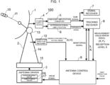
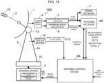
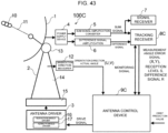
- An antenna system 100 as illustrated in FIG. 1 , mainly includes an antenna 1, an antenna mount 2, an antenna driver 3, a power supply device 4, a sum signal amplification converter 5, a difference signal amplification converter 6, a signal receiver 7, a tracking receiver 8, and an antenna control device 9.
- the antenna 1 receives a radio wave 11 from a moving object 10 such as a satellite or a rocket.
- the antenna mount 2 supports the antenna 1 to be able to change an orientation direction that is a direction in which the antenna 1 is oriented.
- the antenna driver 3 drives the antenna mount 2 thereby changing the orientation direction of the antenna 1.
- the power supply device 4 supplies power to the antenna 1 after amplifying a transmission signal, and generates, based on reception signals received by the antenna 1, a sum signal (SUM) and a difference signal (ERROR) by using the auxiliary power supply system of the power supply device 4.
- the sum signal amplification converter 5 amplifies the sum signal and converts the signal to an intermediate frequency.
- the difference signal amplification converter 6 amplifies the difference signal and converts the signal to the intermediate frequency.
- the signal receiver 7 demodulates the sum signal and acquires data transmitted by the moving object 10.
- the tracking receiver 8 generates, from the sum signal and the difference signal, measurement angle error signals X and Y for driving the antenna mount 2.
- the antenna control device 9 controls the antenna driver 3 such that the antenna 1 is oriented in the arrival direction.
- the arrival direction is a direction from which the radio wave transmitted by the moving object 10 comes and arrives.
- the orientation direction of the antenna 1 is measured by an orientation direction measurer 12.
- the orientation direction of the antenna 1 can be changed by the antenna mount 2.
- the orientation direction is expressed by an azimuth angle and an elevation angle.
- the orientation direction measurer 12 is inputted with signals outputted by angle detection encoders (an encoder for the azimuth angle and an encoder for the elevation angle) that are attached to the antenna 1.
- the orientation direction measurer 12 measures the actual measurement value of the azimuth angle (referred to as the AZ actual angle) of the main beam axis of the antenna 1 based on the signal outputted by the encoder for the azimuth angle, and measures the actual measurement value of the elevation angle (referred to as the EL actual angle) of the main beam axis based on the signal outputted by the encoder for the elevation angle.
- the orientation direction measurer 12 outputs the AZ actual angle and the EL actual angle to the antenna control device 9.
- the orientation direction is represented by a horizon coordinate system based on a combination of (i) an azimuth angle where north is zero degrees and clockwise angles from north are positive and (ii) an elevation angle where directing the horizon is zero degrees.
- the antenna mount 2 includes an elevation angle mount 13, an azimuth angle mount 14, and a base 15.
- the elevation angle mount 13 supports the antenna 1.
- the azimuth angle mount 14 supports the elevation angle mount 13 rotatably around an elevation angle axis (EL-axis) extending horizontally.
- the base 15 supports the azimuth angle mount 14 rotatably around an azimuth angle axis (AZ-axis) extending vertically.
- the azimuth angle may be referred to as an AZ-angle or AZ.
- the EL angle also may be referred to as an EL-angle or EL.
- the antenna control device 9 can be applied also to an X/Y type of antenna mount.
- the antenna driver 3 includes an elevation angle driver 16 and an azimuth angle driver 17.
- the elevation angle driver 16 changes the elevation angle of the elevation angle mount 13 relative to the azimuth angle mount 14.
- the azimuth angle driver 17 changes the azimuth angle of the azimuth angle mount 14 relative to the base 15.
- the elevation angle driver 16 and the azimuth angle driver 17 each have a servo control system.
- the power supply device 4 amplifies a transmission signal of a microwave frequency band to a predetermined power and supplies the amplified power to the antenna 1. Furthermore, the power supply device 4 generates, based on the reception signals received by the antenna 1, a sum signal (SUM) and a difference signal (ERROR) by using the auxiliary power supply system of the power supply device 4.
- the sum signal amplification converter 5 amplifies the sum signal and converts the frequency of the amplified sum signal to a lower frequency.
- the difference signal amplification converter 6 amplifies the difference signal and converts the frequency of the amplified difference signal to the lower frequency.
- the signal receiver 7 processes the sum signal received from the sum signal amplification converter 5 as a modulated communication signal and demodulates the processed signal. The sum signal and the difference signal are inputted to the tracking receiver 8.
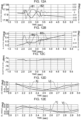
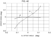
- FIG. 2 is a diagram illustrating an example of changes, with respect to an offset angle, of the sum signal and the difference signal that are generated by the antenna 1 and inputted to the tracking receiver 8.
- the sum signal is represented by a solid line and the difference signal is represented by a dashed line.
- the offset angle is an angle by which the orientation direction changes from a state of directing the moving object 10.
- the offset angle is zero degrees when the orientation direction of the antenna 1 is oriented toward the moving object 10. In a case where the offset angle is zero degrees, the signal intensity of the sum signal is at its highest, whereas the signal intensity of the difference signal is at its lowest.
- the tracking receiver 8 generates, based on the sum signal and the difference signal, measurement angle error signals X and Y for driving the antenna 1, and outputs the measurement angle error signals X and Y to the antenna control device 9.
- the measurement angle error signal X corresponds to an azimuth angle error of the orientation direction
- the measurement angle error signal Y corresponds to an elevation angle error of the orientation direction.
- the antenna control device 9 generates a drive signal for controlling the azimuth angle and the elevation angle of the main beam axis of the antenna 1 and outputs the drive signal to the antenna driver 3.
- the antenna control device 9 controls the azimuth angle and the elevation angle of the main beam of the antenna 1 based on the measurement angle error signals.
- the controlling, based on measurement angle error signals, such that the measurement angle error signals approach zero, is referred to as automatic tracking.
- a method in which the direction of the main beam of the antenna 1 is controlled in accordance with a predetermined change scenario is referred to as program tracking.
- program tracking there is a case where control is performed based on an orbit prediction value, inputted from the external, of the moving object 10 and the change scenario and a case where control is performed only by either the change scenario or the orbit prediction value.
- the orbit prediction value is data representing the position of the moving object 10 per a predetermined width of time.
- the position of the moving object 10 is represented by an azimuth angle and an elevation angle in the direction, on the celestial sphere, of the moving object 10 as viewed from a predetermined observation point.
- the orbit prediction values inputted from the external for example, every second, are interpolated by interpolation calculation to obtain values at a finer time width of 10 msec, for example.
- the antenna control device 9 uses the interpolated orbit prediction values.
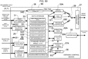
- FIG. 3 is a block diagram illustrating the configuration of the tracking receiver.
- the tracking receiver 8, as illustrated in FIG. 3 includes a sum signal AGC circuit 18, a difference signal AGC circuit 19, a 90 degree phase shifter 20, an I-signal detector 21, a Q-signal detector 22, a data storage 23, a coordinate converter 24, and an interface 25.
- AGC is an abbreviation of automatic gain control, that is, automatic amplification ratio control.
- the sum signal AGC circuit 18 is inputted with a sum signal outputted by the antenna 1, the sum signal AGC circuit 18 amplifies the inputted sum signal.
- the amplification ratio of the sum signal AGC circuit 18 changes in accordance with the amplitude of the sum signal.
- the sum signal AGC circuit 18 outputs the amplified sum signal to the 90 degree phase shifter 20 and the I-signal detector 21.
- the sum signal AGC circuit 18 outputs, to the difference signal AGC circuit 19, an amplification voltage.
- the amplification voltage increases in proportion to the increase in the amplification ratio.
- the difference signal AGC circuit 19 is inputted with the difference signal outputted by the antenna 1 and the amplification voltage outputted by the sum signal AGC circuit 18.
- the difference signal AGC circuit 19 changes the amplification ratio in accordance with the value of the amplification voltage inputted from the sum signal AGC circuit 18 and amplifies the inputted difference signal. That is, the difference signal AGC circuit 19 amplifies the inputted difference signal by the amplification ratio that is proportional to the amplification ratio of the sum signal AGC circuit 18. Consequently, the amplified difference signal outputted from the difference signal AGC circuit 19 is amplified by the amplification ratio that is proportional to the amplification ratio of the amplified sum signal outputted from the sum signal AGC circuit 18.
- the difference signal AGC circuit 19 outputs the amplified difference signal to the I-signal detector 21 and the Q-signal detector 22.
- the 90 degree phase shifter 20 shifts (changes) the phase of the amplified sum signal outputted from the sum signal AGC circuit 18 by 90 degrees.
- the 90 degree phase shifter 20 outputs, to the Q-signal detector 22, the amplified sum signal with phase shifted by 90 degrees.
- the shifting of the phase by 90 degrees means that the phase is increased by 90 degrees.
- the I-signal detector 21 detects the difference signal that is outputted from the difference signal AGC circuit 19 by the sum signal (sum signal without phase shifting) that is outputted from the sum signal AGC circuit 18. In other words, the I-signal detector 21 outputs a product of the sum signal outputted from the sum signal AGC circuit 18 and the difference signal outputted from the difference signal AGC circuit 19. The I-signal detector 21 outputs the detected signal (hereinafter referred to as the "I-signal") to the coordinate converter 24.
- the axis where the I-signal is detected is referred to as the I-axis.
- the Q-signal detector 22 detects the difference signal outputted from the difference signal AGC circuit 19 by the sum signal outputted from the 90 degree phase shifter 20. In other words, the Q-signal detector 22 outputs the product of the sum signal outputted from the 90 degree phase shifter 20 and the difference signal outputted from the difference signal AGC circuit 19. The Q-signal detector 22 outputs the detected signal (hereinafter referred to as the "Q-signal") to the coordinate converter 24.
- the axis where the Q-signal is detected is referred to as the Q-axis.
- the phase correction value 51 and the sensitivity coefficient 52 used by the coordinate converter 24 are stored in the data storage 23.
- the phase correction value 51 and the sensitivity coefficient 52 are calculated by the antenna control device 9.
- the phase correction value 51 is a correction value by which the phase of the I-axis and the Q-axis are corrected.
- the I-axis where the measurement angle error signal X is detected aligns with a U-axis (described later) that corresponds to the azimuth angle of the orientation direction
- the Q-axis where the measurement angle error signal Y is detected aligns with a V-axis (described later) that corresponds to the elevation angle of the orientation direction.
- the sensitivity coefficient 52 is a factor of proportionality between the magnitude of the measurement angle error signal and the absolute value of the error of the orientation direction.
- the coordinate converter 24 uses the phase correction value 51 and the sensitivity coefficient 52 to perform coordinate conversion on the I-signal and the Q-signal and then outputs the measurement angle error signals X and Y. Coordinate conversion is described later.
- the measurement angle error signals X and Y are outputted by the tracking receiver 8.
- the signal intensity (reception level) of the sum signal inputted to the sum signal AGC circuit 18 is also outputted by the tracking receiver 8.
- the measurement angle error signal is an arrival direction error representing the difference between the arrival direction and the orientation direction of the antenna 1.
- the arrival direction is the direction from which the radio wave 11 comes and arrives.
- the measurement angle error signal is generated from the sum signal and the difference signal of the reception signals.
- the tracking receiver 8 is a measurement angle processor that is inputted with the sum signal and the difference signal of the reception signals and calculates an arrival direction error.
- the interface 25 receives, from the antenna control device 9, a monitoring signal indicating whether or not the antenna control device 9 is operating normally.
- the interface 25 transmits, to the antenna control device 9, a monitoring signal indicating whether or not the tracking receiver 8 is operating normally. Transmission/reception of data such as the phase correction value y and sensitivity coefficient K and control signals between the tracking receiver 8 and the antenna control device 9 is also performed.
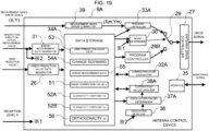
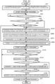
- FIG. 4 is a block diagram illustrating the configuration of the antenna control device according to Embodiment 1.
- the antenna control device 9 includes an orbit prediction value data generator 26, an antenna drive controller 27, a program controller 28, a changeover switch 29, a mode determiner 30, an error measurement data generator 31, a correction value calculator 32, a tracking controller 33, a data storage 34, an interface 35, an oscillation detector 36, an oscillation cause determiner 37, and a correction value updater 38.
- the orbit prediction value data generator 26 generates orbit prediction value data 53 obtained by performing interpolation calculation of orbit prediction values inputted externally every second, for example, to obtain values at a finer time width of 10 msec, for example. Then, the orbit prediction value data generator 26 stores the generated orbit prediction value data 53 into the data storage 34.
- the antenna drive controller 27 generates a drive signal that drives the antenna driver 3 such that the difference between the command value being inputted and the direction orientation direction of the antenna 1 approaches zero.
- the antenna drive controller 27 amplifies the power of the drive signal to a level necessary for the antenna driver 3.
- the program controller 28 generates a command value based on the orbit prediction value data 53 and the change scenario 54 and outputs the generated command value to the antenna drive controller 9.
- An example of the change scenario 54 is illustrated in FIG. 5 .
- the change scenario 54 indicates a time transition of orientation operation amount by which the orientation direction is changed from the orbit prediction value that is indicated by the orbit prediction value data 53.
- the term "orientation operation amount" is the amount by which the orientation direction is changed from the orbit prediction value.
- the program controller 28 outputs, as the command value, an orientation direction obtained by adding the orientation operation amount indicated in the change scenario 54 to the predicted position of the moving object 10 every control time based on the orbit prediction value data 53.
- the changeover switch 29 switches between program tracking and automatic tracking.
- the antenna drive controller 27 is inputted with the command value outputted by the program controller 28.
- the changeover switch 29 is on the automatic tracking side
- the antenna drive controller 27 is inputted with the command value calculated by the tracking controller 33.
- the state during which the antenna drive controller 27 is inputted with the command value outputted by the tracking controller 33 is referred to as "the tracking controller 33 is in operation” and the state during which the antenna drive controller 27 is inputted with the command value outputted by the program controller 28 is referred to as "program controller 28 is in operation”.
- the mode determiner 30 determines whether to operate in program tracking mode or automatic tracking mode. If the mode determiner 30 determines that it is necessary to change the mode, the mode determiner 30 changes the mode changeover switch 29 to the side to be used. The mode switching between program tracking and automatic tracking can be changed also through an instruction given by a user.
- the error measurement data generator 31 generates error measurement data 55 while the program controller 28 is in operation.
- the error measurement data 55 contains an AZ actual angle and an EL actual angle measured by the orientation direction measurer 12 and measurement angle error signals outputted by the tracking receiver 8, all of which are measured at the time of the command value of the same orientation direction.
- the error measurement data 55 contains the measurement angle error signals X and Y and the AZ actual angle and the EL actual angle being actual measurement values of the orientation direction when the reception signals (sum signal and difference signal), from which the measurement angle error signals are obtained, are inputted.
- the generated error measurement data 55 is stored in the data storage 34.
- the correction value calculator 32 calculates, based on at least three pieces of the error measurement data 55, a correction parameter that can correct the measurement angle error signals and make the difference between the orientation direction of the antenna 1 and the arrival direction approach zero.
- the error measurement data 55 for each of the at least three pieces are generated at conditions in which the program controller 28 outputs the command values that are different each other.
- the correction parameters to be calculated are the phase correction value 51 that is an angle by which the measurement angle error signal is rotated, and the sensitivity coefficient 52 by which the measurement angle error signal is multiplied.
- the calculated phase correction value 51 and the sensitivity coefficient 52 are stored in the data storage 23 included in the tracking receiver 8 and into the data storage 34. The method by which the correction value calculator 32 calculates the phase correction value 51 and the sensitivity coefficient 52 is described later.
- the tracking controller 33 calculates command value obtained by adding the measurement angle error signal and the change caused by the orbit prediction value to the orientation direction actual measurement value. In a case where an orbit prediction value of the communication counterpart does not exist, the change caused by the orbit prediction value is set to zero.
- the interface 35 receives, from the tracking receiver 8, a monitoring signal indicating whether or not the tracking receiver 8 is operating normally.
- the interface 35 transmits, to the tracking receiver 8, the monitoring signal indicating whether or not the antenna control device 9 is operating normally. Also, the transmission/reception of data such as the phase correction value y and sensitivity coefficient K and control signals between the tracking receiver 8 and the antenna control device 9 is also performed.
- the oscillation detector 36 detects oscillation. Oscillation is a phenomenon where the orientation direction of the antenna 1 periodically changes during automatic tracking. FIG. 14 and FIG. 16 illustrate examples where oscillation is occurring.
- the oscillation detector 36 checks the orientation direction actual measurement values within, for example, a predetermined length of time, and detects oscillations in a case where there is a fluctuation greater than or equal to a predetermined threshold.
- the oscillation cause determiner 37 activates the error measurement data generator 31 and the correction value calculator 32 multiple times.
- the oscillation cause determiner 37 determines the cause of the oscillation based on multiple phase correction values y and sensitivity coefficients K.
- the oscillation cause determiner 37 determines a phase shift in which the phase of the measurement angle error signal has changed or a sensitivity shift in which the sensitivity coefficient has changed as being the cause of the oscillation.
- the oscillation detector 36 may not be provided in a case where, during automatic tracking, the error measurement data generator 31 and the correction value calculator 32 are always operated periodically.
- the correction value updater 38 updates the phase correction value y.
- the correction value updater 38 updates the sensitivity coefficient K.
- the updated phase correction value ⁇ new and the sensitivity coefficient Knew are stored in the data storage 23 of the tracking receiver 8 and the data storage 33.
- the newly calculated phase correction value ynow is determined based on at least one piece of y among the phase correction values y calculated at and after the time when oscillation is detected. In the case where ynow is determined based on multiple pieces of y, the phase correction value ynow is determined by use of an appropriate method such as the averaging or median operation.
- the phase correction values y calculated at and after the time when oscillation is detected are union of the y calculated for determining the cause of oscillation and the y calculated after identifying the cause of oscillation.
- the newly calculated sensitivity coefficient Know is determined based on at least one piece of K among the sensitivity coefficients K calculated at and after the time when oscillation is detected. In the case where Know is determined based on multiple pieces of K, the newly calculated sensitivity coefficient Know is determined by use of an appropriate method such as the averaging or median operation.
- the sensitivity coefficients K calculated at and after the time when oscillation is detected are union of the K calculated for determining the cause of oscillation and the K calculated after identifying the cause of oscillation.
- FIG. 5 is a diagram illustrating an example of a trajectory in which an orientation direction is changed when program tracking is performed by the antenna control device according to Embodiment 1.
- the trajectory that changes by the orbit prediction value is represented by one point G o on the celestial sphere defined in the horizontal coordinate system.
- G o is referred to as the reference celestial sphere point.
- the celestial sphere point G o is the prediction direction being the orientation direction predicted based on the orbit prediction value.
- the reference celestial sphere point is (i) an orientation direction of the orbit prediction value at one time point determined appropriately in a determined change scenario 54, such as the starting point, an intermediate point, or an end point of the change scenario 54 or (ii) a centroid of the orbit prediction values during a time period.
- the celestial sphere points and the reference celestial sphere point G o that are used to create the error measurement data 55 are denoted by white circles.
- the vertical direction shown in the figure is referred to as the V-direction.
- the V-direction is the direction of the great circle on the celestial sphere in which the elevation angle changes.
- the direction of the great circle that is perpendicular to the V-direction on the celestial sphere is referred to as the U-direction.
- the U-direction is the horizontal direction in the figure. Since the trajectory on the celestial sphere in which the azimuth angle changes while the elevation angle is constant is a small circle, strictly speaking, the trajectory differs from the U-direction.
- the difference between (i) the trajectory on the celestial sphere in which the azimuth angle changes in a range with minute changes and (ii) the U-direction can be ignored.
- the great circle of the U-direction which passes on the reference celestial sphere point is referred to as the U-axis.
- the great circle of the V-direction which passes on the reference celestial sphere point is referred to as the V-axis.
- the offset angle is ⁇
- the frequency of the rotation of the program command value is f
- the angular velocity 2 ⁇ f
- the time elapsed from the start of the change scenario 54 is t.
- the offset angle ⁇ is the reference angle used for changing an orientation direction.
- Equation (3) and Equation (4) mean that the program command value ( ⁇ u, ⁇ v), which is the command value of the orientation direction, is calculated such that the angular difference from reference celestial sphere point G o is in a range within the offset angle ⁇ .
- the offset angle ⁇ is a predetermined maximum angle difference relative to the angular difference between the reference celestial sphere point G o and the command value of the orientation direction.
- the program command value moves so that its trajectory forms a circle on the celestial sphere, the circle has a center located at G 0 and a radius ⁇ .
- the ⁇ is a small value that is less than or equal to approximately 1/10 of the half width of the antenna 1.
- the drop in the reception level when circular movement is made in accordance with the program command value is less than approximately 0.3 dB including the control response error of the antenna 1.
- the error measurement data 55 is created during program tracking based on ten or more celestial sphere points G j .
- the command value represented by a pair of the azimuth angle and the elevation angle are inputted.
- the command value of the azimuth angle and the elevation angle corresponding to the celestial sphere point G assumed to be (AZ0(t), EL0(t)), is expressed as follows.
- the frequency f is set to approximately 1 Hz , and the time during which the orientation direction of the antenna device 1 changes becomes short. Also, in a case where the phase calculation accuracy is low because the antenna device 1 being unable to maintain proper tracking at 1 Hz due to the frequency band characteristics of the antenna servo loop, the frequency may be decreased to less than 1 Hz in accordance with the frequency band characteristics of the servo loop.
- the command value of the orientation direction may be changed using a movement other than circular movement, for example, square-like movement and grid-like movement.
- the offset angle ⁇ is a change reference angle used as a reference for changing the command value in a change scenario.
- the change range of the command value is proportional to the offset angle ⁇ .
- the maximum angle difference being the maximum value of the angle differences from the reference celestial sphere points of command values that change by the change scenario, is determined by the offset angle ⁇ .
- the orientation direction is expressed by the U-axis and V-axis coordinate system with the reference celestial sphere point G o being the origin.
- the U-axis component of the orientation direction is referred to as the U-angle whereas the V-axis component of the orientation direction is referred to as the V-angle.
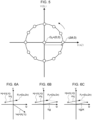
- FIGS. 6A, 6B, and 6C illustrate the process for correcting a measurement angle error victory based on a phase correction value and a sensitivity coefficient calculated by the antenna control device according to Embodiment 1.
- FIGS. 6A, 6B, and 6C illustrate the variables at the time of the program correction value G j .
- FIG. 6A illustrates the actual measurement value Hj of the orientation direction, the arrival direction P 0 , the actual measurement value error vector Vhj of the arrival direction that is determined based on the actual measurement value Hj, and the measurement angle error vector Vsj that is obtained from the sum signal and the difference signal.
- FIG. 6B illustrates the vector Vgj where Vsj is rotated by the phase correction value y. Vhj and Vgj direct in the same direction.
- FIG. 6C illustrated a case where Vgj is multiplied by the sensitivity coefficient K. The direction and magnitude of Vhj and Vgj/K are the same.
- the coordinate converter 24 uses the phase correction value ⁇ and the sensitivity coefficient K to perform coordinate conversion and then outputs the measurement angle error signals X and Y.
- the measurement angle error signals before correction are represented by the variables Xb and Yb.
- X Y 1 K cos ⁇ ⁇ sin ⁇ sin ⁇ cos ⁇ Xb Yb
- Equation (13) K ⁇ X1 ⁇ X2 ⁇ sin ⁇ + Y1 ⁇ Y2 ⁇ cos ⁇
- Equation (14) and Equation (15) are each squared and then added together.
- U2 ⁇ U1 2 + V 2 ⁇ V1 2 K 2 ⁇ X1 ⁇ X2 2 + Y 1 ⁇ Y2 2
- Equation (22) and Equation (23) can be expressed as follows.
- Equation (24) ⁇ h ⁇ ⁇ s
- the correction value calculator 32 uses error measurement data 55 generated by the program command value G j of N pieces (at least three pieces), and can calculate the phase correction value y and the sensitivity coefficient K with reduced influence of noise. Additionally, the variables shown below are defined.
- Xfj and Yfj can be calculated using the following equations.
- Xfj Yfj K cos ⁇ sin ⁇ ⁇ sin ⁇ cos ⁇ Du ⁇ Uj Dv ⁇ Vj
- Du ⁇ Uj Dv ⁇ Vj 1 K cos ⁇ ⁇ sin ⁇ sin ⁇ cos ⁇ Xfj Yfj
- the correction value calculator 32 determines y and K such that the following error function E is minimized.
- E ⁇ Xj ⁇ Xfj 2 + Yj ⁇ Yfj 2
- the error function E is the sum of squares of post-correction residuals for N pieces of the error measurement data 55.
- Each of the post-correction residuals is the difference between (i) the arrival direction error (Xfj, Yfj) obtained by correcting the actual measurement value error (Du -Uj, Dv - Vj) by using the correction parameters including the phase correction value and (ii) the arrival direction error (Xj, Yj) inputted from the tracking receiver 8.
- Equation (30) ⁇ Xj 2 + Yj 2 ⁇ 2 ⁇ K ⁇ ⁇ Du ⁇ Uj ⁇ Xj ⁇ cos ⁇ ⁇ Yj ⁇ sin ⁇ ⁇ 2 ⁇ K ⁇ ⁇ Dv ⁇ Vj ⁇ Xj ⁇ sin ⁇ + Yj ⁇ cos ⁇ + K 2 ⁇ ⁇ Du ⁇ Uj 2 + Dv ⁇ Vj 2
- Equation (31) becomes the following.
- E N ⁇ xs0 + ys0 ⁇ 2 N ⁇ K ⁇ Du ⁇ u0 ⁇ x0 ⁇ cos ⁇ ⁇ ⁇ 0 ⁇ sin ⁇ + d0 ⁇ cos ⁇ ⁇ e0 ⁇ sin ⁇ ⁇ 2 N ⁇ K Dv ⁇ v0 ⁇ x0 ⁇ sin ⁇ + ⁇ 0 ⁇ cos ⁇ + f0 ⁇ sin ⁇ + g0 ⁇ cos ⁇ + N ⁇ K 2 ⁇ Du ⁇ u0 2 + Du ⁇ v0 2 + us0 + vs0
- ⁇ tan ⁇ 1 f 0 ⁇ e 0 / d 0 + g 0
- K ⁇ d 0 + g 0 2 + f 0 ⁇ e 0 2 / us 0 + vs 0
- this method has a feature that enables to calculate the prediction value errors (Du, Dv) even when there is a deviation between the orbit prediction value and the satellite position, and enables to calculate the phase correction value y and the sensitivity coefficient K that are not influenced with the forecast value errors.
- the post-correction values with respect to Uj and Vj may be calculated as follows.
- phase correction value y and the sensitivity coefficient K are calculated by minimizing the error function E2 that is represented by Ufj and Vfj.
- E 2 K 2 ⁇ ⁇ Ufj ⁇ Uj 2 + Vfj ⁇ Vj 2
- the error function E2 is the sum of squares of post-correction residuals for N pieces of the error measurement data 55.
- Each of the post-correction residuals is the difference between (i) the actual measurement value error (Du - Ufj, Dv - Vfj) obtained by correcting the arrival direction error with the correction parameters including the phase correction value y and (ii) the actual measurement value error (Du - Uj, Dv - Vj).
- the error function E2 is the same as the error function E. Even in a case where the error function E2 is minimized, the phase correction value y and the sensitivity coefficient K can be calculated to be the same value as that calculated when the error function E is minimized.
- phase correction value y and the sensitivity coefficient K calculated by the correction value calculator 32 are stored in the data storage 23 included in the tracking receiver 8 and into the data storage 34.
- the values that are stored are not the calculated values without further processing. Rather, as illustrated in Equation (1) and Equation (2), the values set before updating are corrected and set.
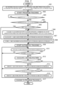
- FIG. 7 is a flowchart illustrating a procedure for tracking the moving object by the antenna control device according to Embodiment 1.
- step S01 information such as the reception frequency and the orbit prediction value are set depending on the moving object 10 to be tracked being a satellite or others.
- step S02 program tracking starts.
- the mode determiner 30 sets the changeover switch 29 to the program tracking side.
- step S03 the mode determiner 30 checks whether a reception level S outputted by the tracking receiver 8 is greater than or equal to a lower limit value Smin. If the reception level S is greater than or equal to the lower limit value Smin (YES in S03), the radio wave 11 from the moving object 10 is considered to be captured, and thus processing proceeds to step S04. If the reception level S is less than the lower limit value Smin (No in S03), S03 is repeated at a predetermined interval.
- step S04 a check is performed as to whether the parameter for phase adjustment is set to the value indicating that phase adjustment is executed in every tracking. If phase adjustment is not to be executed in every tracking, a check is performed, in step S05, as to whether the phase correction value y and so on for the frequency used for present tracking, had been calculated. If phase adjustment is executed in every tracking in S04 or if calculation is not finished in step S05, step S06 is performed.
- the program controller 28 outputs the command value of the orientation direction of the antenna device 1 to change in accordance with a predetermined change scenario. While the orientation direction changes in accordance with the change scenario, the error measurement data generator 31, at a predetermined time interval, generates error measurement data 55 and stores into the data storage 34.
- step S07 the correction value calculator 32 calculates the phase correction value y and the sensitivity coefficient K and stores them into the data storage 34.
- a change scenario 54 is performed and a phase correction value y and a sensitivity coefficient K are calculated.
- the program controller 28 changes the command value of the orientation direction in accordance with the change scenario 54 and generates error measurement data 55 for three or more pieces.
- the phase correction value y and the sensitivity coefficient K are calculated based on the generated error measurement data 55.
- the moving object 10 is supposed to be an artificial satellite orbiting at the orbit altitude of 500 Km.
- the elevation angle is approximately 5 degrees.
- the noise superimposed on the measurement angle error signal is approximated using a Gauss random number and the effective value of that magnitude is set to be 0.003° rms (root mean square).
- the noise superimposed on the actual measurement value of the orientation direction of the antenna 1 is approximated using a Gauss random number and that magnitude is set to be 0.003° rms.
- the first example is illustrated in FIG. 8 to FIG. 10 .
- the simulation conditions are as follows.
- FIG. 8 illustrates a trajectory of actual measurement values Hj of the orientation direction of the antenna 1 and a trajectory of the measurement angle error vectors Vsj calculated from the sum signal and the difference signal in a case where the orbit prediction values are represented by a single point on the celestial sphere .
- the orientation direction actual measurement value Hj is denoted by a solid line with white circles.
- the measurement angle error vector Vsj is denoted by a dashed-line with white rhombuses.
- FIGS. 9A, 9B, 9C, 9D, and 9E are diagrams illustrating temporal changes of measurement data in the case of FIG. 8 .
- the orientation direction is changed between 2 seconds and 3 seconds from the start of the simulation.
- FIG. 9A illustrates temporal changes of an azimuth angle actual measurement value 81 and an azimuth angle servo system tracking error 82.
- FIG. 9B illustrates temporal changes of an elevation angle actual measurement value 83 and an elevation angle servo system tracking error 84.
- FIG. 9C illustrates temporal changes of the signal intensity of the sum signal.
- FIG. 9D illustrates temporal changes of the azimuth angle actual measurement value Uj and the azimuth angle measurement angle error signal Xj.
- FIG. 9E illustrates temporal changes of the elevation angle actual measurement value Vj and the measurement angle error signal Yj.
- the result of calculation by the correction value calculator 32 is as follows.
- the trajectory of the post-correction measurement angle error vector Vaj corrected based on the measurement angle vector Vsj by using y, K, Du, and Dv and the trajectory of the measurement angle error vector Vsj are illustrated in FIG. 10 .
- the post-correction measurement angle error vector Vaj is denoted by a dash-dot line with black triangles.
- the actual measurement value Hj of the orientation direction is not shown for ease in viewing this figure.
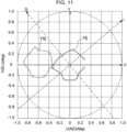
- FIG. 11 to FIG. 13 The second example is illustrated in FIG. 11 to FIG. 13 .
- the simulation conditions are as follows.
- FIG. 11 to FIG. 13 are expressed in a manner similar to that in FIG. 8 to 10 .
- FIG. 13 also illustrates the actual measurement value Hj of the orientation direction.
- the result of calculation by the correction value calculator 32 is as follows.
- step S10 the tracking controller 33 calculates command value obtained by adding the measurement angle error signals X and Y to the orbit prediction value and then outputs the command value to the antenna drive controller 27.
- the oscillation detector 36 checks periodically in step S11 whether or not automatic tracking is oscillating.
- Oscillation refers to a phenomenon where the orientation direction changes periodically as illustrated in FIG. 14 and FIG. 16 .
- the difference between the orbit prediction value and the orientation direction actual measurement value with respect to the azimuth angle or the elevation angle is greater than or equal to a predetermined threshold, it is determined that there is oscillation.
- Other methods may be used for detecting oscillation. Any method may be used as a method for detecting oscillation, as long as the method can determine that the azimuth angle or the elevation angle fluctuates with respect to an orbit prediction value.
- the oscillation cause determiner 37 activates the error measurement data generator 31 and the correction value calculator 32 multiple times to calculate multiple pieces of the phase correction value y and the sensitivity coefficient K.
- step S13 a check is performed as to whether or not phase shift is the cause of the oscillation.
- Phase shift is a state in which the phase correction cannot be accurately performed using the phase correction value y, because phase of the measurement angle signal is shifted and causes oscillation.
- a condition for determining that the oscillation is caused by phase shift is, for example, a condition in which the multiple calculated phase correction values y are within range not including zero degrees and having a predetermined width.
- the oscillation cause determiner 37 is a phase shift detector that determines that phase shift is occurring when multiple calculated phase correction values y calculated while the tracking controller is in operation are within range not including zero degrees and having the predetermined width.
- the multiple calculated phase correction values y are within the range not including zero degrees and having the predetermined width, it is determined that oscillation is occurring due to phase shift. In a case where the multiple calculated phase correction values are within a predetermined range including zero degrees, it is understood that phase correction value y is not shifted. Also, in a case where the phase correction value y fluctuates beyond the predetermined width, it can be considered that oscillation is occurring due to another factor and that the phase correction value y is fluctuating under the influence of the oscillation.
- the correction value updater 38 in step S14, updates the phase correction value y as illustrated in Equation (1), and stores the phase correction value ⁇ new into the data storage 34 and the data storage 23.
- the correction value updater 38 is a phase correction value updater that updates the phase correction value when the oscillation cause determiner 37 detects phase shift.
- step S15 a check is performed as to whether or not the oscillation is caused by sensitivity shift.
- Sensitivity shift is a state in which correction cannot be accurately performed using the sensitivity coefficient K due to the shift in the sensitivity coefficient of the measurement angle error signal.
- a condition for determining that the oscillation is caused by sensitivity shift is, for example, a condition in which multiple calculated sensitivity coefficients K are within a range not including 1 and having a predetermined width. In the case where the multiple calculated sensitivity coefficients K are within a predetermined range not including 1, it is determined that oscillation is occurring due to sensitivity shift.
- the oscillation cause determiner 37 is a sensitivity shift detector that detects sensitivity shift when multiple sensitivity coefficients K calculated while the tracking controller is in operation are within range not including 1 and having the predetermined width.
- the correction value updater 38 in step S16, updates the sensitivity coefficient K as illustrated in Equation (2), and stores the sensitivity coefficient Knew into the data storage 34 and the data storage 23.
- the correction value updater 38 is a sensitivity coefficient updater that updates the sensitivity coefficient when the oscillation cause determiner 37 detects sensitivity shift.
- step S17 If it is not determined that the oscillation is caused by sensitivity shift NO in S15), the cause is unknown, and thus the mode is changed to program tracking in step S17.
- An impact on the communication quality caused by a deviation between the moving object 10 and the orientation direction during program tracking depends on the accuracy of the orbit prediction value and the orientation accuracy inherent to the antenna 1.
- the communication quality can be determined on the basis of, for example, whether a bit error rate generated by the signal receiver 7 satisfies a requirement criterion.
- the saved correction parameter may be used to resume automatic tracking. If the saved correction parameter is used, the saved correction parameter is set in the data storage 34 and the data storage 23. If the moving object 10 is captured, the changeover switch 29 switches to the automatic tracking side.
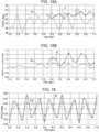
- FIG. 14 and FIGS. 15A and 15B illustrate the simulation results in the case where oscillation occurred due to phase shift.
- FIG. 14 is a diagram illustrating temporal changes of actual measurement values of the azimuth angle and the elevation angle.
- the solid line with black dots denotes the azimuth angle (AZ) and the dash-dot line with white triangles denotes the elevation angle (EL).
- FIGS. 15A and 15B illustrate temporal changes of the phase correction value y and the sensitivity coefficient K.
- FIG. 15A illustrates temporal changes of the phase correction value ⁇ .
- FIG. 15B illustrates temporal changes of the sensitivity coefficient K.
- the solid line with the black dots denotes the phase correction value ⁇ and the sensitivity coefficient K that are corrected in the present invention.
- the dashed line with white diamonds denotes the phase correction value yw and the sensitivity coefficient Kw that are calculated by that in Patent Literature 3.
- the phase correction value y can be calculated from 5.9 seconds.
- the method of Patent Literature 3 can calculate the phase correction value yw from 5 seconds.
- the phase correction value y fluctuates less than the phase correction value yw, and it can be recognized that the phase correction value y can be calculated more accurately. If the predetermined width at which the phase correction value y is determined to be fluctuating is 5 degrees, it can be determined that the phase correction value y is not fluctuating. However, the phase correction value yw calculated using the method of Patent Literature 3 is determined to be fluctuating.
- the sensitivity coefficient K fluctuates somewhat more than the sensitivity coefficient Kw.
- FIG. 16 and FIGS. 17A and 17B illustrate the simulation results in a case where oscillation occurred due to the shift in sensitivity coefficient K.
- FIG. 16 is similar to FIG. 14 .
- FIGS. 17A and 17B illustrated temporal changes of the phase correction value y and the sensitivity coefficient K.
- FIG. 17A is a diagram illustrating temporal changes of the phase correction value.
- FIG. 17B is a diagram illustrating temporal changes of the sensitivity coefficient K.
- the phase correction value y fluctuates less than the phase correction value yw, and it can be recognized that the phase correction value y can be calculated more accurately.
- the sensitivity coefficient K also fluctuates less than the sensitivity coefficient Kw.
- phase correction value y For the phase correction value y, all of the calculated phase correction values y are within a 5 degree range including 0 degrees. It is not determined that the phase correction value ⁇ is shifted. The phase correction value yw is fluctuating by over 20 degrees. In a case where the phase correction value yw is used, it is not determined that there is oscillation caused by the shift of the phase correction value yw.
- the sensitivity coefficient K is in a range from approximately 2.0 to approximately 2.5.
- the sensitivity coefficient Kw caused by the method of Patent Literature 3 is in a range of approximately 1.9 to approximately 3.0.
- a term referred to as the fluctuation width indicates the ratio of the largest value of the calculated sensitivity coefficients divided by the smallest value of the calculated sensitivity coefficients. If it is determined that the sensitivity coefficient K is fluctuating on the condition of the fluctuation width being, for example, greater than or at 130%, it can be determined that the sensitivity coefficient is not fluctuating.
- the threshold with respect to the fluctuation width such as 130% is determined in advance.
- the sensitivity coefficient Kw calculated using the method in Patent Literature 3 is determined to be fluctuating.
- the fluctuation width may be a value obtained by dividing the largest value of the calculated sensitivity coefficients by an average value of the calculated sensitivity coefficients. Alternatively, the value may be obtained by dividing the average value of the calculated sensitivity coefficients by the smallest value of the calculated sensitivity coefficients.
- the fluctuation width may be calculated any way as long as the magnitude of fluctuation of the sensitivity coefficients can be expressed.
- the phase adjustment and sensitivity adjustment can be automatically performed before the starting of tracking of the moving object. Therefore, erroneous operation due to human error can be prevented and work efficiency can be enhanced.
- the present invention provides more accurate calculation of the phase correction value and the sensitivity coefficient than method described in Patent Literature 3 even in a case where the signal-to-noise ratio of the difference signal is low.
- it can be determined whether the oscillation is caused by phase shift or sensitivity shift, and if the cause is phase shift, the oscillation can be eliminated by updating the phase correction value. If the cause is sensitivity shift, the oscillation can be eliminated by updating the sensitivity coefficient.
- the phase correction value and the sensitivity coefficient can be calculated accurately even when the signal-to-noise ratio of the difference signal is low, the measurement angle error signals can be calculated more accurately than conventional methods, and thus the communication counterpart can be tracked accurately.
- phase correction value y and the sensitivity coefficient K are both calculated, only the phase correction value y may be calculated. In the case where only the phase correction value y is calculated, a predetermined value or a value of 1 is used for the sensitivity coefficient K.
- the error function E is a sum of squares of post-correction residuals for N pieces of the error measurement data.
- Each of the post-correction residuals used in the error function E is the difference between the arrival direction error and the actual measurement value error corrected based on the phase correction value and the sensitivity coefficient.
- the error function E2 is the sum of squares of post-correction residuals for N pieces of the error measurement data.
- Each of the post-correction residuals used in the error function E2 is the difference between the actual measurement value error and the arrival direction error corrected based on the phase correction value and the sensitivity coefficient.
- the phase correction value and the sensitivity coefficient may be obtained by correcting one of the actual measurement value error and the arrival direction error by each of the phase correction value and the sensitivity coefficient, and by minimizing the sum of squares of post-correction residuals for N pieces of the error measurement data.
- An example of correcting one of the actual measurement value error and the arrival direction error by each of the phase correction value and the sensitivity coefficient is a case where the actual measurement value error is corrected based on the phase correction value, and the arrival direction error is corrected based on the sensitivity coefficient.
- a correction parameter other than the phase correction value and the sensitivity coefficient may be used for performing the correction.
- additional correction parameters include orthogonality and the sensitivity coefficient set as having different values for the azimuth angle direction and the elevation angle direction. Orthogonality expresses degree of a difference from 90 degrees the phase difference between the I-axis and the Q-axis that are used for generating the measurement angle error signals X and Y from the sum signal and the difference signal.
- Embodiment 2 is obtained by modifying Embodiment 1 such that a case where detection axes used for performing quadrature detection on the measurement angle error signals X and Y is not orthogonal is taken into account and a case where the sensitivity coefficient is set to be different for AZ and EL is also taken into account. Also, the coordinate converter 24 of the tracking receiver 8 is set such that substantially no coordinate conversion is performed. A tracking receiver that is not equipped with a coordinate converter is also applicable to Embodiment 2.
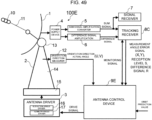
- FIG. 18 is a diagram illustrating a configuration of an antenna system including an antenna control device according to Embodiment 2 of the present invention.
- FIG. 19 is a block diagram illustrating a configuration of the antenna control device according to Embodiment 2.
- An antenna control device 9A that is included in an antenna system 100A additionally includes a measurement angle error corrector 39, and a correction value calculator 32A, a tracking controller 33A, and a data storage 34A are modified.
- the measurement angle error corrector 39 performs corrections to the measurement angle error signals, which is performed by the coordinate converter 24 included in the tracking receiver 8. Therefore, the phase correction value y is set to zero degrees and the sensitivity coefficient K is set to 1 in the data storage 23 included in the tracking receiver 8. By setting the values in this manner, it can be made equivalent to the case in which the coordinate converter 24 do nothing. Thus, it is unnecessary for the antenna control device 9A to set and change the phase correction value y and the sensitivity coefficient K in the data storage 23. In a case where the coordinate converter 24 can perform the same conversion as the measurement angle error corrector 39, the data is stored in the data storage 23 and the coordinate converter 24 can perform the conversion using the data stored in the data storage 23. Also, in this case, the antenna control device 7A may not be equipped with the measurement angle error corrector 39.
- the data storage 34A stores an AZ sensitivity coefficient 52A and an EL sensitivity coefficient 52B instead of storing the sensitivity coefficient 52 and also stores the orthogonality 56.
- the AZ sensitivity coefficient 52A is an azimuth angle sensitivity coefficient that is a sensitivity coefficient for the azimuth angle direction.
- the EL sensitivity coefficient 52B is an elevation sensitivity coefficient that is a sensitivity coefficient for the elevation angle direction.
- the orthogonality 56 expresses degree of a difference from 90 degrees the phase difference between the I-axis and the Q-axis that are used for generating the measurement angle error signals X and Y from the sum signal and the difference signal.
- the orthogonality 56 expresses the difference between (i) the angle between the I-axis and the Q-axis that are two axes where quadrature detection is performed on the measurement angle error signals X and Y and (ii) 90 degrees.
- the radiation pattern of the main lobe of the radio wave that is received by the antenna 1 can be expressed also in a case where the radiation pattern is determined by parameters having different values for azimuth angle and elevation angle.
- the AZ sensitivity coefficient 52A, the EL sensitivity coefficient 52B, and the variables representing orthogonality 56 are defined as follows.
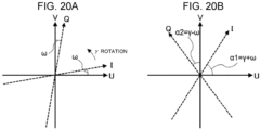
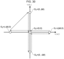
- FIGS. 20A and 20B The coordinate conversion using the orthogonality ⁇ and the phase correction value y is illustrated in FIGS. 20A and 20B.
- FIG. 20A illustrates a case where the orthogonality ⁇ between IQ axes and the UV axes is changed. In the case where 45° > ⁇ > 0°, the I-axis exists above the U-axis in the first quadrant and the Q-axis exists to the right of the V-axis.
- FIG. 20B illustrates a state in which the state shown in FIG. 20A is rotated by phase correction value y.
- the measurement angle error corrector 39 corrects the measurement angle error signals by using the correction parameters ⁇ , ⁇ , Ku, and Kv.
- the following variables are defined.
- the measurement angle error corrector 39 corrects the measurement angle error signals expressed by the following equation.
- Xm Ym cos ⁇ ⁇ ⁇ / Ku ⁇ sin ⁇ ⁇ ⁇ / Ku sin ⁇ + ⁇ / Kv cos ⁇ + ⁇ / Kv X Y
- the tracking controller 33A calculates a command value obtained by adding (i) the change caused by the orbit prediction value and (ii) the measurement angle error signals Xm and Ym corrected by the measurement angle error corrector 39 to (iii) the orientation direction actual measurement value.
- the correction value calculator 32A calculates Xfj and Yfj using Equation (41) and determines the correction parameters ( ⁇ , ⁇ , Ku, and Kv, Du, and Dv) such that the error function E defined by Equation (29) is minimized. Since there are six correction parameters, the number N of the error measurement data 55 is greater than or equal to four pieces. The greater N is, the more accurate calculation of the correction parameters becomes.
- Equation (30) ⁇ Xj 2 + Yj 2 ⁇ 2 ⁇ Ku ⁇ cos ⁇ 1 2 ⁇ ⁇ ⁇ Du ⁇ Uj ⁇ Xj ⁇ cos ⁇ + ⁇ ⁇ Yj ⁇ sin ⁇ + ⁇ ⁇ 2 ⁇ Kv ⁇ cos ⁇ 1 2 ⁇ ⁇ ⁇ Dv ⁇ Vj ⁇ Xj ⁇ sin ⁇ ⁇ ⁇ + Yj ⁇ cos ⁇ ⁇ ⁇ + 1 + sin 2 ⁇ ⁇ sin 2 ⁇ ⁇ Ku 2 ⁇ ⁇ Du ⁇ Uj 2 + 1 ⁇ sin 2 ⁇ ⁇ sin 2 ⁇ ⁇ Kv 2 ⁇ ⁇ Dv ⁇ Vj 2 ⁇ 2 ⁇ sin 2 ⁇ ⁇ Ku ⁇ Kv ⁇ ⁇ Du ⁇ Uj ⁇ Dv ⁇ Vj ⁇ cos ⁇ 2 2 ⁇
- Ku and Kv are replaced as follows.
- Ku Ku / cos 2 ⁇
- Kv Kv / cos 2 ⁇
- Equation (44) is substituted with Equation (45) and Equation (46) as follows. Equation (44) may be used without substituting with Equation (45) and Equation (46).
- E ⁇ Xj 2 + Yj 2 ⁇ 2 ⁇ Ku ⁇ ⁇ Du ⁇ Uj ⁇ Xj ⁇ cos ⁇ + ⁇ ⁇ Yj ⁇ sin ⁇ + ⁇ ⁇ 2 ⁇ Kv ⁇ ⁇ Dv ⁇ Vj ⁇ Xj ⁇ sin ⁇ ⁇ ⁇ + Yj ⁇ cos ⁇ ⁇ ⁇ + 1 + sin 2 ⁇ ⁇ sin 2 ⁇ ⁇ Ku 2 ⁇ ⁇ Du ⁇ Uj 2 + 1 ⁇ sin 2 ⁇ ⁇ sin 2 ⁇ ⁇ Kv 2 ⁇ ⁇ Dv ⁇ Vj 2 ⁇ 2 ⁇ sin 2 ⁇ ⁇ Ku ⁇ Kv ⁇ ⁇ Du ⁇ Uj ⁇ Dv ⁇ Vj
- Equation (44A) As an equation without ⁇ , the following additional variables are defined.
- Equation (44A) becomes as follows.
- E N ⁇ xs0 + ys0 ⁇ 2 N ⁇ Ku ⁇ Du ⁇ u0 ⁇ r0 ⁇ cos ⁇ + ⁇ + ⁇ + d0 ⁇ cos ⁇ + ⁇ ⁇ e0 ⁇ sin ⁇ + ⁇ ⁇ 2 N ⁇ Kv ⁇ Dv ⁇ v0 ⁇ r0 ⁇ sin ⁇ + ⁇ ⁇ ⁇ + f 0 ⁇ sin ⁇ ⁇ ⁇ + g0 ⁇ cos ⁇ ⁇ ⁇ + N ⁇ Ku 2 ⁇ Du ⁇ u0 2 + us0 ⁇ 1 + sin 2 ⁇ ⁇ sin 2 ⁇ + N ⁇ Kv 2 ⁇ Dv ⁇ v0 2 + vs0 ⁇ 1 ⁇ sin 2 ⁇ ⁇ sin 2 ⁇ ⁇ 2 ⁇ N ⁇ Ku ⁇ Kv ⁇ Du ⁇ ⁇ 2 ⁇ N ⁇ Ku ⁇ Kv ⁇ Du ⁇ ⁇ 2
- ⁇ E/ ⁇ 0.
- approximate values are calculated by assigning initial values to ⁇ , ⁇ , Ku, Kv, Du, and Dv and by correcting the parameters by way of repeated calculation.
- ⁇ Xj/ ⁇ ⁇ Xfj/ ⁇ , for example, is established.
- Equation (48) By substituting the left side of Equation (48) with Equation (49) and Equation (50), the following is obtained.
- Equation (51) to Equation (56) Six linear equations are obtained in Equation (51) to Equation (56) with respect to six unknown variables ( ⁇ , ⁇ y, ⁇ Ku, ⁇ Kv, ⁇ Du, ⁇ Dv).
- Equation (51) to Equation 56 By solving simultaneous equations for Equation (51) to Equation 56), ( ⁇ , ⁇ , ⁇ Ku, ⁇ Kv, ⁇ Du, ⁇ Dv) can be calculated.
- Equation (45) and Equation (46) In a case where Ku and Kv are converted in Equation (45) and Equation (46), Ku and Kv are calculated by inversely applying Equation (45) and Equation (46).
- the initial values of the correction parameters may be predetermined or may be calculated as follows based on the correction parameters ( ⁇ 0, K0, Du0, and Dv0) calculated by the method in Embodiment 1.
- ⁇ , ⁇ ,Ku ,Kv ,Du ,Dv 0 , ⁇ 0 , K0 ,K0 ,Du0 ,Dv0
- Equation (59) is converted to an equation without ⁇ as follows.
- E N ⁇ xs 0 + ys 0 ⁇ 2 N ⁇ Ku ⁇ Du ⁇ u 0 ⁇ r 0 ⁇ cos ⁇ + ⁇ + d 0 ⁇ cos ⁇ ⁇ e 0 ⁇ sin ⁇ ⁇ 2 N ⁇ Kv ⁇ Dv ⁇ v 0 ⁇ r 0 ⁇ sin ⁇ + ⁇ + f 0 ⁇ sin ⁇ + g 0 ⁇ cos ⁇ + N ⁇ Ku 2 ⁇ Du ⁇ u 0 2 + us 0 + Kv 2 ⁇ Dv ⁇ v 0 2 + vs 0
- m 0 e 0 2 ⁇ g 0 2 / vs 0 + 2 ⁇ d 0 ⁇ f 0 / us 0
- n 0 d 0 2 ⁇ f 0 2 / us 0 ⁇ 2 ⁇ e 0 ⁇ g 0 / vs 0
- E ⁇ Xj 2 + Yj 2 ⁇ 2 ⁇ K ⁇ ⁇ Du ⁇ Uj ⁇ Xj ⁇ cos ⁇ + ⁇ ⁇ Yj ⁇ sin ⁇ + ⁇ ⁇ 2 ⁇ K ⁇ ⁇ Dv ⁇ Vj ⁇ Xj ⁇ sin ⁇ ⁇ ⁇ + Yj ⁇ cos ⁇ ⁇ ⁇ + K 2 ⁇ 1 + sin 2 ⁇ ⁇ sin 2 ⁇ ⁇ ⁇ Du ⁇ Uj 2 + 1 ⁇ sin 2 ⁇ ⁇ sin 2 ⁇ ⁇ ⁇ Dv ⁇ Vj 2 ⁇ ⁇ 2 ⁇ sin 2 ⁇ ⁇ ⁇ Du ⁇ Uj ⁇ Dv ⁇ Vj
- K K / cos 2 ⁇
- Equation (62) is converted to an equation without ⁇ as follows.
- E N ⁇ xs 0 + ys 0 ⁇ 2 N ⁇ K ⁇ Du ⁇ u 0 ⁇ r 0 ⁇ cos ⁇ + ⁇ + ⁇ + d 0 ⁇ cos ⁇ + ⁇ ⁇ e 0 ⁇ sin ⁇ + ⁇ ⁇ 2 N ⁇ K ⁇ Dv ⁇ v 0 ⁇ r 0 ⁇ sin ⁇ + ⁇ ⁇ ⁇ + f 0 ⁇ sin ⁇ ⁇ ⁇ + g 0 ⁇ cos ⁇ ⁇ ⁇ + N ⁇ K 2 ⁇ 1 + sin 2 ⁇ ⁇ sin 2 ⁇ ⁇ Du ⁇ u 0 2 + us 0 + 1 ⁇ sin 2 ⁇ ⁇ sin 2 ⁇ ⁇ Dv ⁇ v 0 2 + vs 0 ⁇ 2 ⁇ sin 2 ⁇ ⁇ Du ⁇ u 0 + ws
- Equation (62A) is somewhat simpler that Equation (44B), Equation (62A) cannot be solved analytically. Similar to the case where ⁇ ⁇ 0 and Ku ⁇ Kv, it is necessary to solve by repeated calculation.
- the error function E2 represented by Ufj and Vfj obtained by correcting Xj and Yj may be set to be minimized.
- Equation (65A) ⁇ Xj ⁇ Yj / N
- Equation (65A) becomes as follows.
- E 2 N ⁇ Ku 2 ⁇ Du ⁇ u 0 2 + us 0 + N ⁇ Kv 2 ⁇ Dv ⁇ v 0 2 + vs 0 ⁇ 2 N ⁇ Ku ⁇ Du ⁇ u 0 ⁇ r 0 ⁇ cos ⁇ + ⁇ ⁇ ⁇ + d 0 ⁇ cos ⁇ ⁇ ⁇ ⁇ e 0 ⁇ sin ⁇ ⁇ ⁇ ⁇ 2 N ⁇ Kv ⁇ Dv ⁇ v 0 ⁇ r 0 ⁇ sin ⁇ + ⁇ + ⁇ + f 0 ⁇ sin ⁇ + ⁇ + g 0 ⁇ cos ⁇ + ⁇ + N ⁇ 1 + sin 2 ⁇ ⁇ sin 2 ⁇ ⁇ xs 0 + N ⁇ 1 ⁇ sin 2 ⁇ ⁇ sin 2 ⁇ ⁇ ys 0 ⁇ 2 N ⁇ sin 2 ⁇ ⁇ zs 0
- the orthogonality ⁇ , the phase correction value y, the AZ sensitivity coefficient Ku, and the EL sensitivity coefficient Kv may be calculated by minimizing the following error function E3.
- E 3 ⁇ Ufj ⁇ Uj 2 + Vfj ⁇ Vj 2
- the error function E3 is the sum of squares of post-correction residuals for N pieces of the error measurement data 55.
- the post-correction residuals are the respective differences between (i) the arrival direction errors (Du - Ufj, Dv - Vfj) corrected by correction parameters including the phase correction value ⁇ and (ii) the actual measurement value errors ((Du - Uj, Dv - Vj).
- a portion of the correction parameters among the orthogonality ⁇ , the phase correction value y, the AZ sensitivity coefficient Ku, and the EL sensitivity coefficient Kv may be used to correct the actual measurement values errors. Either the actual measurement value error or the arrival direction error is corrected by each of the correction parameters.
- correction parameters that minimizes the sum of squares of post-correction residuals for N pieces of the measurement error data can be obtained.
- the post-correction residuals are differences between a post-correction actual measurement value and a post-correction arrival direction error.
- the post-correction actual measurement value and the post-correction arrival direction error are the actual measurement value and the arrival direction error obtained after correcting based on each of the correction parameters.
- the correction parameters calculated by the correction value calculator 32A are stored in the data storage 34A.
- the values to be stored are the calculated values without further processing.
- FIG. 21 is a flowchart illustrating operation of the antenna control device according to Embodiment 2. The points that differ from those in FIG. 7 of Embodiment 1 are described.
- the correction value calculator 32A calculated the phase correction value y, the orthogonality ⁇ , the AZ sensitivity coefficient Ku, and the EL sensitivity coefficient Kv and stores this calculated data into the data storage 34A.
- the y, ⁇ , Ku, and Kv that had been calculated are stored in the data storage 34A. Since the coordinate converter 24 of the tracking receiver 8 cannot perform correction taking the orthogonality ⁇ into account and correction using sensitivity coefficients Ku and Kv that are different for the azimuth angle direction and the elevation angle direction, the data cannot be stored in the data storage 23 of the tracking receiver 8.
- the measurement angle error corrector 39 calculates the measurement angle error signals X and Y while taking into account the phase correction value y, the orthogonality ⁇ , the AZ sensitivity coefficient Ku, and the EL sensitivity coefficient Kv and outputs the measurement angle error signals Xm and Ym.
- the tracking controller 33A calculates the command value by adding the measurement angle error signals Xm and Ym to the orbit prediction value and outputs the command value to the antenna drive controller 27.
- the oscillation cause determiner 37A activates multiple times the error measurement data generator 31 and the correction value calculator 32A to calculate multiple sets of the phase correction value y, the AZ sensitivity coefficient Ku, and the EL sensitivity coefficient Kv.
- a check is performed as to whether or not oscillation is caused by phase shift.
- An example of the condition to determine that oscillation is caused by phase shift is that the values obtained by subtracting (i) ⁇ that is used by the measurement angle error corrector 39 from (ii) the calculated phase correction values y, are within a range not including zero degrees and having a predetermined width.
- step S14A the correction value updater 38A stores the newly calculated phase correction value ⁇ into the data storage 34. Since the measurement angle error signal that is outputted by the tracking receiver 8A in Embodiment 2 is not corrected by the phase correction value ⁇ , it is sufficient that the phase correction value ⁇ calculated by the correction value calculator 32A is stored without further processing.
- a check is performed as to whether or not oscillation is caused by sensitivity shift.
- Examples of the condition to determine that oscillation is caused by sensitivity shift are that the values obtained by dividing (i) the calculated AZ sensitivity coefficients Ku by (ii) Ku that is used by the measurement angle error corrector 39, are within a range not including 1 and having a predetermined width, or, that the values obtained by dividing (i) the calculated EL sensitivity coefficients Kv by (ii) Kv that is used by the measurement angle error corrector 39, are within a range not including 1 and having a predetermined width.
- the correction value updater 38A stores the newly calculated AZ sensitivity coefficient Ku and the EL sensitivity coefficient Kv into the data storage 34.
- the correction value calculator 32A calculates correction parameters such as the orthogonality ⁇ and sensitivity coefficients that are different for the azimuth angle direction and the elevation angle direction. Three examples are used to describe the correction parameters that are calculated by the correction value calculator 32A.
- the first example is illustrated in FIG. 8 to FIG. 10 and the results of calculation by the correction value calculator 32A are as follows.
- the post-correction measurement angle error vector Vaj that is obtained by correcting the measurement angle error vector Vsj with the correction parameters ( ⁇ , ⁇ , Ku, Kv, Du, Dv) is illustrated in FIG. 22 .
- This Vaj is closer to the Vsj than the Vaj illustrated in FIG. 10 .
- the second example is illustrated in FIG. 11 to FIG. 13 and the results of calculation by the correction value calculator 32A are as follows.
- the post-correction measurement angle error vector Vaj that is obtained by correcting the measurement angle error vector Vsj with the correction parameters ( ⁇ , ⁇ , Ku, Kv, Du, Dv) is illustrated in FIG. 23 .
- This Vaj is closer to the Vsj than the Vaj illustrated in FIG. 13 .
- FIGS. 24 to 26 The third example is illustrated in FIGS. 24 to 26 .
- the simulation conditions are set as indicated below.
- FIGS. 24 to 26 are expressed similarly to FIG. 8 to FIG. 10 .
- the results of calculation by the correction value calculator 32A are as follows.
- FIG. 27 is a diagram illustrating a trajectory of the measurement angle error signal corrected by the phase correction value and the sensitivity coefficients calculated by the antenna control device according to Embodiment 1, as a comparison example. Since the orthogonality is not taken into account, the Vaj and the Vsj are slightly more apart from each other than those in FIG. 26 .
- Embodiment 2 since the orthogonality, the AZ sensitivity coefficient, and the EL sensitivity coefficient are taken into account, the correction parameters that correct the measurement angle error signal can be more accurately calculated than in the case of Embodiment 1.
- Embodiment 3 is a case where a calibration tower (collimation) is used to adjust the phase and sensitivity in advance. By doing so, when a moving object such as a rocket is tracked, tracking can be performed even when there is no orbit prediction value of the moving object or the accuracy of the orbit prediction value is low.
- a calibration tower collimation
- FIG. 28 is a diagram illustrating a configuration of an antenna system including an antenna control device according to Embodiment 3.
- FIG. 29 is a block diagram illustrating a configuration of an antenna control device according to Embodiment 3.
- An antenna system 100B includes a calibration tower 71.
- the calibration tower 71 emits a radio wave 11B of a predetermined frequency.
- the calibration tower 71 is installed at a position where the antenna 1 can receive the radio wave 11B emitted by the calibration tower 71.
- the calibration tower 71 is a test radio wave source that is installed on the ground at a predetermined position with respect to the antenna 1 and emits radio waves.
- the calibration tower 71 is a temporary communication counterpart during program tracking in order to acquire error measurement data for calculating correction parameters.
- An orbit prediction value of a moving object 10B does not exist. Therefore, the antenna control device 9B does not include an orbit prediction value data generator 26.
- a program controller 28B and a correction value calculator 32B are modified.
- a data storage 34B includes a change scenario 54B.
- the change scenario 54B is a scenario for changing the orientation direction of the antenna 1 in a way to be different from that in Embodiment 1.
- the program controller 28B defining the direction toward the calibration tower 71 as a reference direction, makes the orientation direction of the antenna 1 to change in a range that is within a predetermined maximum angle difference.
- FIG. 30 is a diagram illustrating an example of a trajectory in which the orientation direction is changed during program tracking by the antenna control device according to Embodiment 3.
- the orientation direction is stationary for at least a predetermined time.
- the offset angle ⁇ is determined such that the offset angle ⁇ exists in a linear region in which sensitivity coefficients are linear.
- the linear region is a region in which the
- the orientation direction of the antenna 1 changes in a state in which the elevation angle of the antenna 1 is close to zero. Therefore, the U-direction offset angle ⁇ , as it is, may be set as the change in the command value of the azimuth angle.
- the correction value calculator 32B calculates the phase correction value y, the AZ sensitivity coefficient Ku, and the EL sensitivity coefficient Kv, and the orthogonality ⁇ as follows.
- the relationship between the measurement angle error signals (X1, Y1) and (X2, Y2) with respect to G 1 and G 2 on the U-axis is illustrated in FIG. 31 .
- the relationship between the measurement angle error signals (X3, Y3) and (X4, Y4) with respect to G 3 and G 4 on the V-axis is illustrated in FIG. 32 .
- the U-axis and the V-axis are direction respectively are a first direction and a second direction orthogonal on the celestial sphere with the reference celestial sphere point G o being the reference.
- the orientation direction is stationary for a predetermined time at two celestial sphere points G 1 and G 2 on the U-axis being the first direction.
- the orientation direction is stationary for a predetermined time at two celestial sphere points G 3 and G 4 on the V-axis being the second direction.
- the correction value calculator 32B calculates at least the phase correction value ⁇ by using the equation for the error measurement data measured at the celestial sphere points G 1 and G 2 and the equation for the error measurement data measured at the celestial sphere points G 3 and G 4 .
- a time sequence example for driving automatically the antenna is illustrated in FIG. 33 .
- the antenna drive controller 27 is a servo-type that does not overshoot
- data acquisition is easy.
- the time during which the antenna 1 is oriented toward a single celestial sphere point is 7 seconds
- the data acquisition time is 3 seconds
- the data sampling time is 0.1 seconds.
- the time period during which data is acquired is 3 seconds anywhere from start to finish of the 7-second time period during which the antenna 1 is oriented toward a single celestial sphere point.
- the correction parameters ( ⁇ , y, Ku, Kv, Du, Dv) are calculated using the method indicated from Equation (71) to Equation (76) with respect to the value obtained by averaging the data acquired in the 3-second data acquisition time period.
- FIG. 34 illustrates the simulation results of measurement angle error signals X and Y.
- the measurement angle error signal X is represented by a bold solid line and the measurement angle error signal Y is represented by a solid line.
- the simulation conditions are as follows.
- the results of calculation by the correction value calculator 32B are as indicated below. Since no noise exists, values equal to the set conditions can be correctly calculated. The same results can be obtained by the correction value calculator 32A of Embodiment 2.
- the correction value calculator 32A uses all data during the time period including time when the orientation direction of the antenna is changing.
- the initial values of the correction value calculator 32A are the correction parameters calculated by the correction value calculator 32B.
- the simulation results of the measurement angle error signals in the case where noise superimposing on the measurement angle error signal is approximated using a Gauss random number and the effective value of that magnitude is set to be 0.01° rms are illustrated in FIG. 35 .
- the actual measurement value of the orientation direction of the antenna 1 is not superimposed with noise.
- the noise is approximately 18% of the offset angle.
- both the correction value calculator 32B and the correction value calculator 32A can calculate the phase correction value ⁇ and so on quite accurately.
- the noise is approximately 180% of the offset angle ⁇ .
- the noise is 10 times of that in FIG. 35 .
- Both the correction value calculator 32B and the correction value calculator 32A calculate correction parameters that do not cause the antenna servo system to oscillate, and thus it can be said that these methods are effective against noise.
- phase adjustment and sensitivity adjustment can be performed automatically by the calibration tower (collimation). Erroneous operation by human can be prevented and work efficiency can be enhanced.
- FIG. 37 to FIG. 42 are used to describe this.
- FIG. 37 is a diagram illustrating measurement angle error signals that are not corrected by correction parameters such as the phase correction value in the case where the azimuth angle is changed.
- FIG. 38 is a diagram illustrating measurement angle error signals that are not corrected in the case where the elevation is changed.
- FIG. 39 is a diagram illustrating measurement angle error signals at 4 points in a linear region used for correction.
- FIG. 39 illustrates a case in which the measurement results are as follows.
- the correction value calculator 32B calculates as follows.
- the measurement angle error signals at 4 points can be obtained as illustrated in FIG. 40 .
- the measurement angle error signal X exists on the U-axis and the measurement angle error signal Y exists on the V-axis. It can be understood that the corrections are performed properly.
- FIG. 41 illustrates the corrected measurement angle error signals in the case where the azimuth angle is changed.
- FIG. 42 illustrates the corrected measurement angle error signals in the case where the elevation angle is changed. It can be understood that the corrections are performed almost properly even in the non-linear region.
- the simulation results illustrated in FIG. 41 and FIG. 42 show that the correction could be made even in the non-linear region by using the phase, orthogonality, and the sensitivity coefficients calculated using data at the 4 points, and that data at 4 points are sufficient for automatic adjustment using a calibration tower (collimation).
- the correction value calculator 32C in such a modified example calculates, for example, as follows.
- Celestial sphere points may be set for generating the error measurement data 55 at more than 3 points on the U-axis. ⁇ 1 and other parameters may be determined such that the sum of squares of the post-correction residuals is minimized similar to that in Embodiment 1. Celestial sphere points may be set for generating the error measurement data 55 at more than 3 points on the V-axis. ⁇ 2 and other parameters may be determined such that the sum of squares of the post-correction residuals is minimized similar to that in Embodiment 1. Celestial sphere points may be set for generating the error measurement data 55 at positions not on the U-axis or the V-axis. ⁇ , ⁇ , and other parameters may be calculated by taking into account at the same time all celestial sphere points for generating the error measurement data 55 similar to that in Embodiment 1.
- Embodiment 4 is a case where the signal intensity of the difference signal is received by an antenna control device and the offset angle ⁇ is changed in accordance with the signal intensity of the difference signal.
- this Embodiment is a modification of Embodiment 2, this can be similarly applied to Embodiment 1 as well.
- FIG. 43 is a diagram illustrating a configuration of an antenna system including an antenna control device according to Embodiment 4 of the present invention.
- a tracking receiver 8C also outputs the signal intensity of the difference signal (difference signal level R).
- FIG. 44 is a block diagram illustrating a configuration of the antenna control device according to Embodiment 4. The points that differ from those in FIG. 19 of Embodiment 2 are described.
- An antenna control device 9C that is included in an antenna system 100C includes an offset angle calculator 40.
- the offset angle calculator 40 changes the offset angle ⁇ in accordance with the difference signal level R. In a case where the difference signal level R is low, the offset angle ⁇ is increased such that a signal intensity is greater than or equal to the lower limit value.
- the data storage 34C is also modified.
- the data storage 34C is modified to include a standard offset angle 57 and an offset angle 58.
- a change scenario 54E is a scenario in which the offset angle 58 is used to change the command value of the orientation direction.
- a program controller 28C uses a changeable offset angle ⁇ to perform program control.
- the standard offset angle 57 is an angle used as offset angle ⁇ in a case where the difference signal level R is sufficiently high.
- the offset angle 58 is an offset angle that is calculated by the offset angle calculator 40 in accordance with the difference signal level R.
- fr ( ⁇ , R) and fs ( ⁇ , S) are functions derived by approximating the antenna pattern by a gauss function, for example.
- the standard offset angle ⁇ 0 is determined such that calculation accuracy of the correction parameters calculated using the error measurement data of N-pieces is greater than or equal to the required accuracy in a case where the difference signal level R is the lower limit value Rmin.
- the offset angle calculator 40 calculates the offset angle in accordance with the difference signal level R and the reception level S as follows.
- the minimum ⁇ in the range may be determined. If the difference signal level R and the reception signal S are divided into multiple ranges, a ⁇ determined to satisfy the condition of each range in the multiple ranges may be used.
- FIG. 45 is a flowchart illustrating operation of the antenna control device according to Embodiment 4. The points that differ from those in FIG. 7 of Embodiment 1 are described.
- Step S21 is added immediately before step S06C.
- the offset angle calculator 40 determines the offset angle ⁇ based on the reception level S and the difference signal level R.
- the orientation direction of the antenna is changed in accordance with a change scenario 54C in which the offset angle ⁇ is used.
- correction parameters such as the phase correction value ⁇ can be calculated in a state in which the signal intensity of the difference signal is higher than that in Embodiment 2 and without causing the reception level S to be reduced more than necessary.
- the determining of the offset angle ⁇ based on the difference signal level R is equivalent to determining the offset angle ⁇ in accordance with the signal-to-noise ratio (SN ratio) provided that the level of noise is constant.
- the offset angle ⁇ may be determined based on the SN ratio of the difference signal instead of the difference level R.
- the offset angle calculator is a change reference angle determiner that determines an offset angle ⁇ such that the signal intensity of the difference signal or the signal-to-noise ratio is greater than or equal to a lower limit value.
- Embodiment 5 is a case in which a SN ratio of a difference signal is received by the antenna control device and a length of a period for performing program tracking is changed in accordance with the SN ratio of the difference signal.
- FIG. 46 is a diagram illustrating a configuration of an antenna system including an antenna control device according to Embodiment 5 of the present invention.
- a tracking receiver 8D outputs the SN ratio Z of the difference signal to an antenna control device 9D.
- FIG. 47 is a block diagram illustrating a configuration of the antenna control device according to Embodiment 5. The points that different from those in FIG. 19 of Embodiment 2 are described.
- the antenna control device 9D included in the antenna system 100D includes a program operation period setter 41.
- the program operation period is a time period during which the command value of the orientation direction is changed in accordance with the change scenario.
- the program operation period setter 41 changes the length of the program operation period in accordance with the SN ratio of the difference signal.
- the program operation period setter 41 increases the length of the program operation period in a case where the SN ratio of the difference signal is less than or equal to a lower limit value.
- the program controller 28D uses a changeable program operation period to perform program control.
- the program operation period is set such that the calculation accuracy of the correction parameters calculated by the correction value calculator 32A is greater than or equal to a predetermined accuracy.
- Reason being, the values that minimize the average of signals containing error have improved SN ratio than that of the original signal.
- Z the SN ratio of an original signal
- Z the SN ratio of an average value of signals of ⁇ -pieces
- the value that minimizes the square error with respect to data of ⁇ -pieces of a single variable is the average value of data of ⁇ -pieces. It can be considered that the SN ratio of variable value that minimizes the square error of multiple variables also is Z ⁇ ⁇ ( ⁇ ).
- a data storage 34D is also modified.
- the data storage 34D includes a standard program operation period 59 and a program operation period 60.
- the change scenario 54D is a scenario that uses the program operation period 60 in changing the command value of the orientation direction.
- the standard program operation period 59 is a length of time (program operation period) during which program tracking is performed in accordance with the change scenario 54D in the case where the difference signal level R is sufficiently high.
- the program operation period 60 is a program operation period set by the program operation period setter 41.
- the error measurement data 53 is generated at a predetermined time interval during operation in accordance with the change scenario 54D.
- the number N of error measurement data for the standard program operation period Ts0 can be determined such that calculation accuracy of the correction parameters calculated based on the error measurement data of N-pieces is greater than or equal to the required accuracy in a case where the SN ratio Z of the difference signal is the lower limit value Zmin.
- the program operation period setter 41 sets the program operation period Ts in accordance with the SN ratio Z of the difference signal as follows.
- the program operation period Ts may be set for each range of the SN ratio of the difference signal.
- a Ts for each range may be determined (i) such that the calculation accuracy of the correction parameters is greater than or equal to the predetermined accuracy and (ii) to be monotonically non-decreasing with respect to decreases in the SN ratio.
- FIG. 48 is a flowchart illustrating operation of the antenna control device according to Embodiment 5. The points that differ from those in FIG. 45 of Embodiment 4 are described.
- step S21D the program operation period setter 41 sets the program operation period Ts based on the SN ratio Z of the difference signal.
- step S06D the command value of the orientation direction of the antenna is changed in accordance with the change scenario in which program operation period Ts is used.
- correction parameters such as the phase correction value ⁇ can be calculated at calculation accuracy that is greater than or equal to the predetermined accuracy.
- the program operation period Ts may be determined.
- the program operation period setter is a data count number determiner that determines a program operation period to be monotonically non-decreasing with respect to decreases in signal intensity or a signal-to-noise ratio in a case where the signal intensity or the signal-to-noise ratio of the difference signal is below a threshold.
- Embodiment 6 is a case in which a difference signal level is received by antenna control device and an offset angle and a length of a period for performing program tracking is changed in accordance with the difference signal level.
- the calculation accuracy of the correction parameters calculated by the correction value calculator 32A in a case where either the offset angle or the length of the period is changed during which program tracking is performed cannot reach or exceed the predetermined accuracy, the predetermined accuracy can be reached or exceeded by changing both the offset angle and the length of time during which the program tracking is performed.
- FIG. 49 is a diagram illustrating a configuration of an antenna system including an antenna control device according to Embodiment 6 of the present invention.
- a tracking receiver 8C outputs a difference signal R to an antenna control device 9D.
- FIG. 50 is a block diagram illustrating a configuration of the antenna control device according to Embodiment 6. The points that differ from those in FIG. 44 of Embodiment 4 are described.
- the antenna control device 9E that is included in an antenna system 100E includes a program operation period setter 41E.
- the program operation period setter 41E changes the length of a program operation period in accordance with the difference signal level R. In a case where the difference signal R is less than or equal to a lower limit value, the program operation period setter 41E increases the length of the program operation period such that the difference signal level R is greater than or equal to the lower limit value.
- a data storage 34E also includes the standard program operation period 59 and the program operation period 60.
- the change scenario 54E is a scenario in which the offset angle 58 and the program operation period 60 are used to change the command value of the orientation direction.
- An offset angle calculator 40E is also modified.
- a program controller 28E uses a changeable offset angle ⁇ and a changeable program operation period Ts to perform program control.
- the number N of the error measurement data for a case in that the standard offset angle ⁇ 0 and the standard program operation period Ts0 is determined such that calculation accuracy of the correction parameters calculated based on the error measurement data of N-pieces is greater than or equal to the required accuracy in a case where the difference signal level R is the lower limit value Rmin.
- the offset angle ⁇ is changed in a case in which calculation accuracy of the correction parameters cannot reach or exceed the predetermined accuracy by lengthening the program operation period Ts. Since the lengthening of the program operation period Ts does not bring a reduction in the reception level S, it is preferable lengthening the program operation period Ts is applied preferentially in a case where not reducing the reception level S is given higher priority.
- the program operation period setter 41E sets the program operation period Ts in accordance with the difference signal R as follows.
- the offset angle calculator 40E operates similarly to the offset angle calculator 40.
- the offset angle calculator 40E operates similarly to the offset angle calculator 40.
- the program operation period setter 41E operates similarly to a case when the program operation period Ts is determined first.
- FIG. 51 is a flowchart illustrating operation of the antenna control device according to Embodiment 5. The points that differ from those in FIG. 48 of Embodiment 5 are described.
- step S21E the program operation period setter 41E sets the program operation period Ts based on the difference signal level R.
- the offset angle calculator 40E determines the offset angle ⁇ based on the reception level S and the difference signal level R.
- the difference signal level R is a value considering the program operation period Ts.
- step S06E the command value of the orientation direction of the antenna is changed in accordance with a change scenario in which the offset angle ⁇ and the program operation period Ts is used.
- the offset angle ⁇ and the program operation period Ts are determined in accordance with the difference signal level R without causing the reception level S to be reduced more than necessary, and thus the correction parameters such as the phase correction value ⁇ can be calculated with the SN ratio of the difference signal in a state that is better than that in Embodiment 2.
Landscapes
- Physics & Mathematics (AREA)
- Engineering & Computer Science (AREA)
- General Physics & Mathematics (AREA)
- Radar, Positioning & Navigation (AREA)
- Remote Sensing (AREA)
- Variable-Direction Aerials And Aerial Arrays (AREA)
Claims (8)
- Steuervorrichtung (9), umfassend:eine Antennenantriebssteuerung (27), die dazu konfiguriert ist, einen Befehlswert einer Orientierungsrichtung eingegeben zu bekommen und einen Antennenantrieb (3) zum Ändern der Orientierungsrichtung zu steuern, wobei die Orientierungsrichtung eine Richtung ist, in die eine Antenne (1) zum Empfangen von Funkwellen von einem Kommunikationsgegenstück zum Erzeugen von Empfangssignalen ausgerichtet ist, sodass sich eine Differenz zwischen dem Befehlswert und der Orientierungsrichtung null annähert,einen Orbit-Vorhersagewertbezieher (26), der dazu konfiguriert ist, einen Orbit-Vorhersagewert des Kommunikationsgegenstücks zu beziehen;eine Programmsteuerung (28), die dazu konfiguriert ist, den Befehlswert, der gemäß einem vorbestimmten Änderungsszenario (54) geändert wird, zu erzeugen und den erzeugten Befehlswert an die Antennenantriebssteuerung (27) auszugeben, wobei das vorbestimmte Änderungsszenario (54) einen Zeitübergang einer Ausrichtungsbetriebsgröße angibt, wobei die Ausrichtungsbetriebsgröße eine Größe ist, um die sich die Orientierungsrichtung von einer Vorhersagerichtung geändert hat, wobei die Vorhersagerichtung die Orientierungsrichtung ist, die basierend auf dem Orbit-Vorhersagewert vorhergesagt wird, wobei der erzeugte Befehlswert eine Orientierungsrichtung ist, die durch Addieren der Orientierungsbetriebsgröße zu der Vorhersagerichtung zu jeder Steuerzeit erlangt wird, wobei die Programmsteuerung (28) dazu konfiguriert ist, den Befehlswert innerhalb eines Bereichs zu erzeugen, in dem eine Winkeldifferenz zu der Vorhersagerichtung kleiner oder gleich einer vorbestimmten maximalen Winkeldifferenz ist;einen Fehlermessdatenerzeuger (31), der dazu konfiguriert ist, Fehlermessdaten (55) zu erzeugen, einschließlich (i) einem Ankunftsrichtungsfehler, der aus einem Summensignal und einem Differenzsignal der Empfangssignale erlangt wird, wobei der Ankunftsrichtungsfehler eine Differenz zwischen der Orientierungsrichtung und einer Ankunftsrichtung, die eine Richtung ist, aus der die Funkwellen kommen und ankommen, darstellt, und (ii) einem tatsächlichen Orientierungsrichtungsmesswert, welcher der tatsächliche Messwert der Orientierungsrichtung ist, wenn die Empfangssignale, die verwendet werden, um den Ankunftsrichtungsfehler zu erlangen, empfangen werden;einen Korrekturwertrechner (32), der dazu konfiguriert ist, basierend auf mindestens drei Teilen der Fehlermessdaten (55), die bei Bedingungen erlangt werden, unter denen die Programmsteuerung (28) die Befehlswerte, die sich voneinander unterscheiden, ausgibt, einen Phasenkorrekturwert (51) zu berechnen, der ein Winkel ist, um den der Ankunftsrichtungsfehler gedreht wird; undeine Verfolgungssteuerung (33), die dazu konfiguriert ist, an die Antennenantriebssteuerung (27) einen Wert als den Befehlswert auszugeben, der durch Addieren (i) des Ankunftsrichtungsfehlers, der basierend auf dem Phasenkorrekturwert (51) korrigiert wurde, zu (ii) dem tatsächlichen Orientierungsrichtungsmesswert erlangt wird; undeinen Umschalter (29), der dazu konfiguriert ist, zwischen Programmverfolgung und automatischer Verfolgung umzuschalten, wobei in einem Fall, in dem sich der Umschalter (29) auf der Seite für Programmverfolgung befindet, der Befehlswert, der durch die Programmsteuerung (28) ausgegeben wird, in die Antennenantriebssteuerung (27) eingegeben wird und in einem Fall, in dem sich der Umschalter (29) auf der Seite für automatische Verfolgung befindet, der Befehlswert, der durch die Verfolgungssteuerung (33) berechnet wird, in die Antennenantriebssteuerung (27) eingegeben wird,wobeider Korrekturwertrechner (32) dazu konfiguriert ist, den Phasenkorrekturwert (51) und einen Empfindlichkeitskoeffizienten (52), der ein Wert eines Verhältnisses zwischen einem tatsächlichen Messwertfehler und dem Ankunftsrichtungsfehler ist, zu berechnen, wobei der tatsächliche Messwertfehler eine Differenz zwischen der Ankunftsrichtung und dem tatsächlichen Orientierungsrichtungsmesswert ist, unddie Verfolgungssteuerung (33) dazu konfiguriert ist, an die Antennenantriebssteuerung (27) einen Wert als den Befehlswert auszugeben, der durch Addieren (i) des Ankunftsrichtungsfehlers, der basierend auf dem Phasenkorrekturwert (51) und dem Empfindlichkeitskoeffizienten (52) korrigiert wurde, zu (ii) dem tatsächlichen Orientierungsrichtungsmesswert erlangt wird,wobeider Korrekturwertrechner (32) dazu konfiguriert ist, basierend auf mindestens vier Teilen der Fehlermessdaten (55), die bei Bedingungen erlangt werden, unter denen die Programmsteuerung (28) die Befehlswerte, die sich voneinander unterscheiden, ausgibt, den Phasenkorrekturwert (51), einen Azimutwinkel-Empfindlichkeitskoeffizienten (52A) und einen Höhenwinkel-Empfindlichkeitskoeffizienten (52B) zu berechnen, wobei der Azimutwinkel-Empfindlichkeitskoeffizient (52A) ein Empfindlichkeitskoeffizient (52) in einer Azimutwinkelrichtung ist und der Höhenwinkel-Empfindlichkeitskoeffizient (52B) ein Empfindlichkeitskoeffizient (52) in einer Höhenwinkelrichtung ist, unddie Verfolgungssteuerung (33) dazu konfiguriert ist, an die Antennenantriebssteuerung (27) einen Wert als den Befehlswert auszugeben, der durch Addieren (i) des Ankunftsrichtungsfehlers, der basierend auf dem Azimutwinkel-Empfindlichkeitskoeffizienten (52A) und dem Höhenwinkel-Empfindlichkeitskoeffizienten (52B) korrigiert wurde, zu (ii) dem tatsächlichen Orientierungsrichtungsmesswert erlangt wird.
- Steuervorrichtung nach Anspruch 1, wobei der Korrekturwertrechner (32) dazu konfiguriert ist, die Ankunftsrichtung, den Phasenkorrekturwert, den Azimutwinkel-Empfindlichkeitskoeffizienten und den Höhenwinkel-Empfindlichkeitskoeffizienten anzunehmen, einen des tatsächlichen Messwertfehlers und des Ankunftsrichtungsfehlers basierend auf jedem des Phasenkorrekturwerts, des Azimutwinkel-Empfindlichkeitskoeffizienten und des Höhenwinkel-Empfindlichkeitskoeffizienten zu korrigieren und den Phasenkorrekturwert, den Azimutwinkel-Empfindlichkeitskoeffizienten und den Höhenwinkel-Empfindlichkeitskoeffizienten zu berechnen, sodass eine Summe von Quadraten von Resten nach Korrektur für die mindestens vier Teile der Fehlermessdaten minimiert ist, wobei der Rest nach Korrektur eine Differenz zwischen (i) einem tatsächlichen Messwertfehler nach Korrektur und (ii) einem Ankunftsrichtungsfehler nach Korrektur ist, wobei der tatsächliche Messwertfehler nach Korrektur und der Ankunftsrichtungsfehler nach Korrektur der tatsächliche Messwertfehler und der Ankunftsrichtungsfehler, die nach Korrigieren basierend auf jedem des Phasenkorrekturwerts, des Azimutwinkel-Empfindlichkeitskoeffizienten und des Höhenwinkel-Empfindlichkeitskoeffizienten erlangt werden, sind.
- Steuervorrichtung (9) nach Anspruch 1, wobeider Korrekturwertrechner (32) dazu konfiguriert ist, den Phasenkorrekturwert (51), eine Orthogonalität (56), die eine Differenz zwischen (i) einem Winkel zwischen zwei Achsen, für die eine Quadraturdetektion an dem Summensignal und dem Differenzsignal durchgeführt wird, und (ii) einem 90-Grad-Winkel ausdrückt, den Azimutwinkel-Empfindlichkeitskoeffizienten (52A) und den Höhenwinkel-Empfindlichkeitskoeffizienten (52B) zu berechnen, unddie Verfolgungssteuerung (33) dazu konfiguriert ist, an die Antennenantriebssteuerung (27) einen Wert als den Befehlswert auszugeben, der durch Addieren (i) des Ankunftsrichtungsfehlers, der basierend auf dem Phasenkorrekturwert (51), der Orthogonalität (56), dem Azimutwinkel-Empfindlichkeitskoeffizienten (52A) und dem Höhenwinkel-Empfindlichkeitskoeffizienten (52B) korrigiert wurde, zu (ii) dem tatsächlichen Orientierungsrichtungsmesswert erlangt wird.
- Steuervorrichtung nach Anspruch 3, wobei der Korrekturwertrechner (32) dazu konfiguriert ist, die Ankunftsrichtung, den Phasenkorrekturwert, die Orthogonalität, den Azimutwinkel-Empfindlichkeitskoeffizienten und den Höhenwinkel-Empfindlichkeitskoeffizienten anzunehmen, einen des tatsächlichen Messwertfehlers und des Ankunftsrichtungsfehlers basierend auf jedem des Phasenkorrekturwerts, der Orthogonalität, des Azimutwinkel-Empfindlichkeitskoeffizienten und des Höhenwinkel-Empfindlichkeitskoeffizienten zu korrigieren und den Phasenkorrekturwert, die Orthogonalität, den Azimutwinkel-Empfindlichkeitskoeffizienten und den Höhenwinkel-Empfindlichkeitskoeffizienten zu berechnen, sodass eine Summe von Quadraten von Resten nach Korrektur für die mindestens vier Teile der Fehlermessdaten minimiert ist, wobei der Rest nach Korrektur eine Differenz zwischen (i) einem tatsächlichen Messwertfehler nach Korrektur und (ii) einem Ankunftsrichtungsfehler nach Korrektur ist, wobei der tatsächliche Messwertfehler nach Korrektur und der Ankunftsrichtungsfehler nach Korrektur der tatsächliche Messwertfehler und der Ankunftsrichtungsfehler, die nach Korrigieren basierend auf jedem des Phasenkorrekturwerts, der Orthogonalität, des Azimutwinkel-Empfindlichkeitskoeffizienten und des Höhenwinkel-Empfindlichkeitskoeffizienten erlangt werden, sind.
- Steuervorrichtung (9) nach einem der Ansprüche 1 bis 4, wobei die Programmsteuerung (28) dazu konfiguriert ist, den Befehlswert, der einen Kreis auf einer Himmelskugel bildet, deren Mittelpunkt sich in der Vorhersagerichtung befindet, zu erzeugen.
- Steuervorrichtung (9) nach einem der Ansprüche 1 bis 5, ferner umfassend:einen Phasenverschiebungsdetektor (37), der dazu konfiguriert ist, eine Phasenverschiebung zu detektieren, wenn Phasenkorrekturwerte (51), die berechnet werden, während sich die Verfolgungssteuerung (33) in Betrieb befindet, innerhalb eines Bereichs liegen, der eine vorbestimmte Breite aufweist, wobei der Bereich keine Nullgrade beinhaltet; undeinen Phasenkorrekturaktualisierer (38), der dazu konfiguriert ist, den Phasenkorrekturwert (51) zu aktualisieren, wenn der Phasenverschiebungsdetektor (37) die Phasenverschiebung detektiert.
- Steuervorrichtung (9) nach einem der Ansprüche 1 bis 6, ferner umfassend:
einen Datenanzahlbestimmer, der dazu konfiguriert ist, eine Anzahl der Fehlermessdaten (55), die durch den Korrekturwertrechner (32) verwendet werden, in Bezug auf Verringerungen einer Signalintensität oder eines Signal-Rausch-Verhältnisses des Differenzsignals als monoton nicht abnehmend zu bestimmen, wenn die Signalintensität oder das Signal-Rausch-Verhältnis des Differenzsignals unter einem Schwellenwert liegt. - Steuervorrichtung (9) nach einem der Ansprüche 1 bis 7, ferner umfassend:
einen Änderungsreferenzwinkelbestimmer, der dazu konfiguriert ist, einen Änderungsreferenzwinkel zu bestimmen, der als eine Referenz zum Ändern des Befehlswerts in dem Änderungsszenario (54) verwendet wird, sodass die Signalempfindlichkeit oder das Signal-Rausch-Verhältnis des Differenzsignals größer oder gleich einem unteren Grenzwert ist.
Applications Claiming Priority (2)
| Application Number | Priority Date | Filing Date | Title |
|---|---|---|---|
| JP2017160264 | 2017-08-23 | ||
| PCT/JP2018/031017 WO2019039514A1 (ja) | 2017-08-23 | 2018-08-22 | 制御装置 |
Publications (3)
| Publication Number | Publication Date |
|---|---|
| EP3674740A1 EP3674740A1 (de) | 2020-07-01 |
| EP3674740A4 EP3674740A4 (de) | 2020-12-02 |
| EP3674740B1 true EP3674740B1 (de) | 2024-12-18 |
Family
ID=65439139
Family Applications (1)
| Application Number | Title | Priority Date | Filing Date |
|---|---|---|---|
| EP18847572.7A Active EP3674740B1 (de) | 2017-08-23 | 2018-08-22 | Steuerungsvorrichtung |
Country Status (5)
| Country | Link |
|---|---|
| US (1) | US11592515B2 (de) |
| EP (1) | EP3674740B1 (de) |
| JP (1) | JP6610840B2 (de) |
| CN (1) | CN111051911B (de) |
| WO (1) | WO2019039514A1 (de) |
Families Citing this family (7)
| Publication number | Priority date | Publication date | Assignee | Title |
|---|---|---|---|---|
| JP7319867B2 (ja) * | 2019-08-23 | 2023-08-02 | 株式会社東芝 | 無線通信システム、無線通信装置、及び無線通信方法 |
| EP4140059A1 (de) * | 2020-05-13 | 2023-03-01 | Viasat Inc. | Antennensysteme und verfahren zur verfolgung von nichtgeosynchronen satelliten |
| US11742933B1 (en) * | 2020-07-31 | 2023-08-29 | Amazon Technologies, Inc. | Antenna control using real-time sensor fusion |
| CN115275604A (zh) | 2021-04-29 | 2022-11-01 | 南宁富联富桂精密工业有限公司 | 天线装置及天线控制方法 |
| US11528102B1 (en) * | 2021-08-18 | 2022-12-13 | International Business Machines Corporation | Built-in-self-test and characterization of a high speed serial link receiver |
| US11662381B2 (en) | 2021-08-18 | 2023-05-30 | International Business Machines Corporation | Self-contained built-in self-test circuit with phase-shifting abilities for high-speed receivers |
| CN119726115B (zh) * | 2024-10-28 | 2025-10-03 | 中国电子科技集团公司第五十四研究所 | 一种基于天线方向图特征匹配的跟踪方法 |
Family Cites Families (25)
| Publication number | Priority date | Publication date | Assignee | Title |
|---|---|---|---|---|
| JPS604896B2 (ja) | 1977-12-05 | 1985-02-07 | 株式会社日立製作所 | 電動機の回転子 |
| FR2452717A1 (fr) * | 1979-03-30 | 1980-10-24 | Thomson Csf | Dispositif de traitement de signaux d'ecartometrie angulaire d'un radar monopulse et radar comportant un tel dispositif |
| JPS58216970A (ja) | 1982-06-10 | 1983-12-16 | Mitsubishi Electric Corp | 飛しよう体追尾方式 |
| JPS6029002A (ja) * | 1983-07-27 | 1985-02-14 | Mitsubishi Electric Corp | 飛しよう体追尾装置 |
| US5043737A (en) | 1990-06-05 | 1991-08-27 | Hughes Aircraft Company | Precision satellite tracking system |
| JP3353991B2 (ja) * | 1994-02-23 | 2002-12-09 | 三菱電機株式会社 | 角度検出装置及び角度検出方法及びレーダ装置 |
| JPH09261149A (ja) * | 1996-03-19 | 1997-10-03 | Mitsubishi Electric Corp | 通信用アンテナの指向制御装置 |
| JP3349927B2 (ja) | 1997-07-18 | 2002-11-25 | 三菱電機株式会社 | 追尾装置 |
| US6061022A (en) * | 1999-06-04 | 2000-05-09 | Itt Manufacturing Enterprises, Inc. | Azimuth and elevation direction finding system based on hybrid amplitude/phase comparison |
| JP3678154B2 (ja) | 2001-02-26 | 2005-08-03 | 三菱電機株式会社 | アンテナ追尾回路の位相調整方法、及びその方法を用いた追尾アンテナ装置 |
| JP3656575B2 (ja) * | 2001-07-23 | 2005-06-08 | 三菱電機株式会社 | 衛星追尾用アンテナ制御装置 |
| US6731240B2 (en) * | 2002-03-11 | 2004-05-04 | The Aerospace Corporation | Method of tracking a signal from a moving signal source |
| JP5721467B2 (ja) | 2011-02-17 | 2015-05-20 | 三菱電機株式会社 | 追尾受信機 |
| JP2013029430A (ja) * | 2011-07-28 | 2013-02-07 | Mitsubishi Electric Corp | 2チャネル追尾装置、および追尾方法 |
| DE102011117591B4 (de) * | 2011-11-03 | 2013-12-24 | Atlas Elektronik Gmbh | Verfahren und Vorrichtung zum Korrigieren systematischer Peilfehler |
| US9658314B2 (en) * | 2012-03-02 | 2017-05-23 | Nokomis, Inc. | System and method for geo-locating and detecting source of electromagnetic emissions |
| JP6004896B2 (ja) | 2012-11-02 | 2016-10-12 | 三菱電機株式会社 | 制御装置、制御方法およびプログラム |
| JP6037805B2 (ja) * | 2012-12-03 | 2016-12-07 | 三菱電機株式会社 | 追尾装置、追尾方法およびプログラム |
| JP2015012568A (ja) * | 2013-07-02 | 2015-01-19 | 三星電子株式会社Samsung Electronics Co.,Ltd. | 指向性制御装置、および指向性制御方法 |
| CN105379013B (zh) * | 2013-07-03 | 2017-11-03 | 三菱电机株式会社 | 跟踪系统及跟踪方法 |
| CN105934852B (zh) * | 2014-01-17 | 2018-11-06 | 三菱电机株式会社 | 天线控制装置及天线装置 |
| US20160164174A1 (en) * | 2014-12-05 | 2016-06-09 | Raytheon Company | Phased array steering |
| JP6722982B2 (ja) * | 2015-05-27 | 2020-07-15 | 三菱電機株式会社 | 衛星追尾装置 |
| WO2019208434A1 (ja) * | 2018-04-27 | 2019-10-31 | 三菱電機株式会社 | 追尾受信機、アンテナ装置および追尾方法 |
| KR102184290B1 (ko) * | 2020-07-06 | 2020-11-30 | 아주대학교산학협력단 | 저궤도 위성 안테나의 조준 오차 보정 방법 |
-
2018
- 2018-08-22 EP EP18847572.7A patent/EP3674740B1/de active Active
- 2018-08-22 US US16/639,213 patent/US11592515B2/en active Active
- 2018-08-22 WO PCT/JP2018/031017 patent/WO2019039514A1/ja not_active Ceased
- 2018-08-22 CN CN201880052929.5A patent/CN111051911B/zh active Active
- 2018-08-22 JP JP2019530236A patent/JP6610840B2/ja active Active
Also Published As
| Publication number | Publication date |
|---|---|
| US11592515B2 (en) | 2023-02-28 |
| EP3674740A1 (de) | 2020-07-01 |
| US20200200853A1 (en) | 2020-06-25 |
| CN111051911B (zh) | 2024-04-19 |
| EP3674740A4 (de) | 2020-12-02 |
| JP6610840B2 (ja) | 2019-11-27 |
| CN111051911A (zh) | 2020-04-21 |
| JPWO2019039514A1 (ja) | 2019-11-07 |
| WO2019039514A1 (ja) | 2019-02-28 |
Similar Documents
| Publication | Publication Date | Title |
|---|---|---|
| EP3674740B1 (de) | Steuerungsvorrichtung | |
| US11327182B2 (en) | Method and device for detecting correction information for an antenna of a vehicle | |
| US5043737A (en) | Precision satellite tracking system | |
| US5274382A (en) | Antenna system for tracking of satellites | |
| RU2207613C1 (ru) | Бортовая аппаратура систем управления беспилотным летательным аппаратом | |
| US20080018524A1 (en) | System and method for estimating airborne radar antenna pointing errors | |
| US20230029048A1 (en) | System and method for near-field testing of a phased array antenna | |
| JP2016223781A (ja) | 衛星追尾装置 | |
| CN114389036A (zh) | 一种卫通相控阵天线低轨卫星闭环跟踪方法及系统 | |
| CN110233352A (zh) | 基于波束倾斜补偿与圆锥扫描融合的深空目标高精度跟踪方法 | |
| US20240204403A1 (en) | Method for Controlling the Pointing of an Antenna | |
| JP5069021B2 (ja) | 追尾アンテナ装置、追尾制御方法およびそのプログラム | |
| KR101514666B1 (ko) | 자이로 및 칼만필터를 이용한 위성지향 안테나의 안정화 시스템 및 위성지향 안테나의 안정화 제어방법 | |
| WO2023146450A1 (en) | Compensating for orientation discrepancy of a first antenna in relation to a second antenna | |
| KR20190087008A (ko) | 이동형 위성통신 단말의 위성추적 성능개선을 위한 스텝 추적과 모노펄스 추적의 혼합추적방법 및 장치 | |
| US7633432B2 (en) | Method and apparatus for precision antenna boresight error estimates | |
| US10495730B1 (en) | Phase agnostic monopulse tracking | |
| JPH07183717A (ja) | 電子ビーム走査アンテナ装置 | |
| KR20170032986A (ko) | 추측항법이 적용된 네비게이션 및 그 제어방법 | |
| JP2000261358A (ja) | 衛星通信受信装置 | |
| KR20180002472A (ko) | 수평 유지 장치를 이용한 위성 추적 장치가 수행하는 위성 추적 방법 | |
| CN121559428B (zh) | 动态环境自适应的瓦特森-瓦特测向系统及方法 | |
| Qin et al. | A communication satellite capture and tracking method based on RSSI trajectory matching | |
| Erdogan | Search algorithm for the ground station antenna of the EIVE satellite | |
| KR20200033598A (ko) | 모노펄스 레이다에서 합/차 채널을 이용한 gmti 표적의 방위각 오차 보정 방법 |
Legal Events
| Date | Code | Title | Description |
|---|---|---|---|
| STAA | Information on the status of an ep patent application or granted ep patent |
Free format text: STATUS: THE INTERNATIONAL PUBLICATION HAS BEEN MADE |
|
| PUAI | Public reference made under article 153(3) epc to a published international application that has entered the european phase |
Free format text: ORIGINAL CODE: 0009012 |
|
| STAA | Information on the status of an ep patent application or granted ep patent |
Free format text: STATUS: REQUEST FOR EXAMINATION WAS MADE |
|
| 17P | Request for examination filed |
Effective date: 20200214 |
|
| AK | Designated contracting states |
Kind code of ref document: A1 Designated state(s): AL AT BE BG CH CY CZ DE DK EE ES FI FR GB GR HR HU IE IS IT LI LT LU LV MC MK MT NL NO PL PT RO RS SE SI SK SM TR |
|
| AX | Request for extension of the european patent |
Extension state: BA ME |
|
| RIC1 | Information provided on ipc code assigned before grant |
Ipc: H01Q 25/02 20060101ALI20200706BHEP Ipc: G01S 3/32 20060101ALI20200706BHEP Ipc: G01S 3/42 20060101AFI20200706BHEP Ipc: H01Q 3/08 20060101ALI20200706BHEP Ipc: G01S 3/02 20060101ALI20200706BHEP |
|
| A4 | Supplementary search report drawn up and despatched |
Effective date: 20201102 |
|
| DAV | Request for validation of the european patent (deleted) | ||
| DAX | Request for extension of the european patent (deleted) | ||
| RIC1 | Information provided on ipc code assigned before grant |
Ipc: H01Q 25/02 20060101ALI20201026BHEP Ipc: H01Q 3/08 20060101ALI20201026BHEP Ipc: G01S 3/42 20060101AFI20201026BHEP Ipc: G01S 3/02 20060101ALI20201026BHEP Ipc: G01S 3/32 20060101ALI20201026BHEP |
|
| STAA | Information on the status of an ep patent application or granted ep patent |
Free format text: STATUS: EXAMINATION IS IN PROGRESS |
|
| 17Q | First examination report despatched |
Effective date: 20230707 |
|
| GRAP | Despatch of communication of intention to grant a patent |
Free format text: ORIGINAL CODE: EPIDOSNIGR1 |
|
| STAA | Information on the status of an ep patent application or granted ep patent |
Free format text: STATUS: GRANT OF PATENT IS INTENDED |
|
| INTG | Intention to grant announced |
Effective date: 20240806 |
|
| GRAS | Grant fee paid |
Free format text: ORIGINAL CODE: EPIDOSNIGR3 |
|
| GRAA | (expected) grant |
Free format text: ORIGINAL CODE: 0009210 |
|
| STAA | Information on the status of an ep patent application or granted ep patent |
Free format text: STATUS: THE PATENT HAS BEEN GRANTED |
|
| AK | Designated contracting states |
Kind code of ref document: B1 Designated state(s): AL AT BE BG CH CY CZ DE DK EE ES FI FR GB GR HR HU IE IS IT LI LT LU LV MC MK MT NL NO PL PT RO RS SE SI SK SM TR |
|
| REG | Reference to a national code |
Ref country code: CH Ref legal event code: EP |
|
| REG | Reference to a national code |
Ref country code: DE Ref legal event code: R096 Ref document number: 602018077795 Country of ref document: DE |
|
| REG | Reference to a national code |
Ref country code: IE Ref legal event code: FG4D |
|
| REG | Reference to a national code |
Ref country code: LT Ref legal event code: MG9D |
|
| PG25 | Lapsed in a contracting state [announced via postgrant information from national office to epo] |
Ref country code: HR Free format text: LAPSE BECAUSE OF FAILURE TO SUBMIT A TRANSLATION OF THE DESCRIPTION OR TO PAY THE FEE WITHIN THE PRESCRIBED TIME-LIMIT Effective date: 20241218 |
|
| PG25 | Lapsed in a contracting state [announced via postgrant information from national office to epo] |
Ref country code: FI Free format text: LAPSE BECAUSE OF FAILURE TO SUBMIT A TRANSLATION OF THE DESCRIPTION OR TO PAY THE FEE WITHIN THE PRESCRIBED TIME-LIMIT Effective date: 20241218 |
|
| PG25 | Lapsed in a contracting state [announced via postgrant information from national office to epo] |
Ref country code: BG Free format text: LAPSE BECAUSE OF FAILURE TO SUBMIT A TRANSLATION OF THE DESCRIPTION OR TO PAY THE FEE WITHIN THE PRESCRIBED TIME-LIMIT Effective date: 20241218 |
|
| PG25 | Lapsed in a contracting state [announced via postgrant information from national office to epo] |
Ref country code: NO Free format text: LAPSE BECAUSE OF FAILURE TO SUBMIT A TRANSLATION OF THE DESCRIPTION OR TO PAY THE FEE WITHIN THE PRESCRIBED TIME-LIMIT Effective date: 20250318 |
|
| REG | Reference to a national code |
Ref country code: NL Ref legal event code: MP Effective date: 20241218 |
|
| PG25 | Lapsed in a contracting state [announced via postgrant information from national office to epo] |
Ref country code: LV Free format text: LAPSE BECAUSE OF FAILURE TO SUBMIT A TRANSLATION OF THE DESCRIPTION OR TO PAY THE FEE WITHIN THE PRESCRIBED TIME-LIMIT Effective date: 20241218 Ref country code: GR Free format text: LAPSE BECAUSE OF FAILURE TO SUBMIT A TRANSLATION OF THE DESCRIPTION OR TO PAY THE FEE WITHIN THE PRESCRIBED TIME-LIMIT Effective date: 20250319 |
|
| PG25 | Lapsed in a contracting state [announced via postgrant information from national office to epo] |
Ref country code: RS Free format text: LAPSE BECAUSE OF FAILURE TO SUBMIT A TRANSLATION OF THE DESCRIPTION OR TO PAY THE FEE WITHIN THE PRESCRIBED TIME-LIMIT Effective date: 20250318 |
|
| PG25 | Lapsed in a contracting state [announced via postgrant information from national office to epo] |
Ref country code: NL Free format text: LAPSE BECAUSE OF FAILURE TO SUBMIT A TRANSLATION OF THE DESCRIPTION OR TO PAY THE FEE WITHIN THE PRESCRIBED TIME-LIMIT Effective date: 20241218 |
|
| REG | Reference to a national code |
Ref country code: AT Ref legal event code: MK05 Ref document number: 1752658 Country of ref document: AT Kind code of ref document: T Effective date: 20241218 |
|
| PG25 | Lapsed in a contracting state [announced via postgrant information from national office to epo] |
Ref country code: SM Free format text: LAPSE BECAUSE OF FAILURE TO SUBMIT A TRANSLATION OF THE DESCRIPTION OR TO PAY THE FEE WITHIN THE PRESCRIBED TIME-LIMIT Effective date: 20241218 |
|
| PG25 | Lapsed in a contracting state [announced via postgrant information from national office to epo] |
Ref country code: PL Free format text: LAPSE BECAUSE OF FAILURE TO SUBMIT A TRANSLATION OF THE DESCRIPTION OR TO PAY THE FEE WITHIN THE PRESCRIBED TIME-LIMIT Effective date: 20241218 |
|
| PG25 | Lapsed in a contracting state [announced via postgrant information from national office to epo] |
Ref country code: ES Free format text: LAPSE BECAUSE OF FAILURE TO SUBMIT A TRANSLATION OF THE DESCRIPTION OR TO PAY THE FEE WITHIN THE PRESCRIBED TIME-LIMIT Effective date: 20241218 |
|
| PG25 | Lapsed in a contracting state [announced via postgrant information from national office to epo] |
Ref country code: IS Free format text: LAPSE BECAUSE OF FAILURE TO SUBMIT A TRANSLATION OF THE DESCRIPTION OR TO PAY THE FEE WITHIN THE PRESCRIBED TIME-LIMIT Effective date: 20250418 |
|
| PG25 | Lapsed in a contracting state [announced via postgrant information from national office to epo] |
Ref country code: PT Free format text: LAPSE BECAUSE OF FAILURE TO SUBMIT A TRANSLATION OF THE DESCRIPTION OR TO PAY THE FEE WITHIN THE PRESCRIBED TIME-LIMIT Effective date: 20250421 |
|
| PG25 | Lapsed in a contracting state [announced via postgrant information from national office to epo] |
Ref country code: EE Free format text: LAPSE BECAUSE OF FAILURE TO SUBMIT A TRANSLATION OF THE DESCRIPTION OR TO PAY THE FEE WITHIN THE PRESCRIBED TIME-LIMIT Effective date: 20241218 |
|
| PG25 | Lapsed in a contracting state [announced via postgrant information from national office to epo] |
Ref country code: AT Free format text: LAPSE BECAUSE OF FAILURE TO SUBMIT A TRANSLATION OF THE DESCRIPTION OR TO PAY THE FEE WITHIN THE PRESCRIBED TIME-LIMIT Effective date: 20241218 Ref country code: RO Free format text: LAPSE BECAUSE OF FAILURE TO SUBMIT A TRANSLATION OF THE DESCRIPTION OR TO PAY THE FEE WITHIN THE PRESCRIBED TIME-LIMIT Effective date: 20241218 |
|
| PG25 | Lapsed in a contracting state [announced via postgrant information from national office to epo] |
Ref country code: SK Free format text: LAPSE BECAUSE OF FAILURE TO SUBMIT A TRANSLATION OF THE DESCRIPTION OR TO PAY THE FEE WITHIN THE PRESCRIBED TIME-LIMIT Effective date: 20241218 |
|
| PG25 | Lapsed in a contracting state [announced via postgrant information from national office to epo] |
Ref country code: CZ Free format text: LAPSE BECAUSE OF FAILURE TO SUBMIT A TRANSLATION OF THE DESCRIPTION OR TO PAY THE FEE WITHIN THE PRESCRIBED TIME-LIMIT Effective date: 20241218 |
|
| PG25 | Lapsed in a contracting state [announced via postgrant information from national office to epo] |
Ref country code: IT Free format text: LAPSE BECAUSE OF FAILURE TO SUBMIT A TRANSLATION OF THE DESCRIPTION OR TO PAY THE FEE WITHIN THE PRESCRIBED TIME-LIMIT Effective date: 20241218 |
|
| PG25 | Lapsed in a contracting state [announced via postgrant information from national office to epo] |
Ref country code: SE Free format text: LAPSE BECAUSE OF FAILURE TO SUBMIT A TRANSLATION OF THE DESCRIPTION OR TO PAY THE FEE WITHIN THE PRESCRIBED TIME-LIMIT Effective date: 20241218 |
|
| REG | Reference to a national code |
Ref country code: DE Ref legal event code: R097 Ref document number: 602018077795 Country of ref document: DE |
|
| P01 | Opt-out of the competence of the unified patent court (upc) registered |
Free format text: CASE NUMBER: UPC_APP_4903_3674740/2025 Effective date: 20250827 |
|
| PG25 | Lapsed in a contracting state [announced via postgrant information from national office to epo] |
Ref country code: DK Free format text: LAPSE BECAUSE OF FAILURE TO SUBMIT A TRANSLATION OF THE DESCRIPTION OR TO PAY THE FEE WITHIN THE PRESCRIBED TIME-LIMIT Effective date: 20241218 |
|
| PGFP | Annual fee paid to national office [announced via postgrant information from national office to epo] |
Ref country code: DE Payment date: 20250702 Year of fee payment: 8 |
|
| PGFP | Annual fee paid to national office [announced via postgrant information from national office to epo] |
Ref country code: FR Payment date: 20250703 Year of fee payment: 8 |
|
| PLBE | No opposition filed within time limit |
Free format text: ORIGINAL CODE: 0009261 |
|
| STAA | Information on the status of an ep patent application or granted ep patent |
Free format text: STATUS: NO OPPOSITION FILED WITHIN TIME LIMIT |
|
| REG | Reference to a national code |
Ref country code: CH Ref legal event code: L10 Free format text: ST27 STATUS EVENT CODE: U-0-0-L10-L00 (AS PROVIDED BY THE NATIONAL OFFICE) Effective date: 20251029 |
|
| 26N | No opposition filed |
Effective date: 20250919 |
|
| REG | Reference to a national code |
Ref country code: CH Ref legal event code: H13 Free format text: ST27 STATUS EVENT CODE: U-0-0-H10-H13 (AS PROVIDED BY THE NATIONAL OFFICE) Effective date: 20260324 |
|
| PG25 | Lapsed in a contracting state [announced via postgrant information from national office to epo] |
Ref country code: MC Free format text: LAPSE BECAUSE OF FAILURE TO SUBMIT A TRANSLATION OF THE DESCRIPTION OR TO PAY THE FEE WITHIN THE PRESCRIBED TIME-LIMIT Effective date: 20241218 |
|
| PG25 | Lapsed in a contracting state [announced via postgrant information from national office to epo] |
Ref country code: LU Free format text: LAPSE BECAUSE OF NON-PAYMENT OF DUE FEES Effective date: 20250822 |
|
| PG25 | Lapsed in a contracting state [announced via postgrant information from national office to epo] |
Ref country code: CH Free format text: LAPSE BECAUSE OF NON-PAYMENT OF DUE FEES Effective date: 20250831 |