EP3676021B1 - Distributeur de fluide avec dispositif d'étanchéité à déplacement nul - Google Patents
Distributeur de fluide avec dispositif d'étanchéité à déplacement nul Download PDFInfo
- Publication number
- EP3676021B1 EP3676021B1 EP18851920.1A EP18851920A EP3676021B1 EP 3676021 B1 EP3676021 B1 EP 3676021B1 EP 18851920 A EP18851920 A EP 18851920A EP 3676021 B1 EP3676021 B1 EP 3676021B1
- Authority
- EP
- European Patent Office
- Prior art keywords
- fluid
- dispenser
- diaphragm
- chamber
- dispensing
- Prior art date
- Legal status (The legal status is an assumption and is not a legal conclusion. Google has not performed a legal analysis and makes no representation as to the accuracy of the status listed.)
- Active
Links
Images

Classifications
-
- B—PERFORMING OPERATIONS; TRANSPORTING
- B05—SPRAYING OR ATOMISING IN GENERAL; APPLYING FLUENT MATERIALS TO SURFACES, IN GENERAL
- B05C—APPARATUS FOR APPLYING FLUENT MATERIALS TO SURFACES, IN GENERAL
- B05C5/00—Apparatus in which liquid or other fluent material is projected, poured or allowed to flow on to the surface of the work
- B05C5/02—Apparatus in which liquid or other fluent material is projected, poured or allowed to flow on to the surface of the work the liquid or other fluent material being discharged through an outlet orifice by pressure, e.g. from an outlet device in contact or almost in contact, with the work
- B05C5/0225—Apparatus in which liquid or other fluent material is projected, poured or allowed to flow on to the surface of the work the liquid or other fluent material being discharged through an outlet orifice by pressure, e.g. from an outlet device in contact or almost in contact, with the work characterised by flow controlling means, e.g. valves, located proximate the outlet
-
- B—PERFORMING OPERATIONS; TRANSPORTING
- B05—SPRAYING OR ATOMISING IN GENERAL; APPLYING FLUENT MATERIALS TO SURFACES, IN GENERAL
- B05C—APPARATUS FOR APPLYING FLUENT MATERIALS TO SURFACES, IN GENERAL
- B05C11/00—Component parts, details or accessories not specifically provided for in groups B05C1/00 - B05C9/00
- B05C11/10—Storage, supply or control of liquid or other fluent material; Recovery of excess liquid or other fluent material
- B05C11/1002—Means for controlling supply, i.e. flow or pressure, of liquid or other fluent material to the applying apparatus, e.g. valves
- B05C11/1034—Means for controlling supply, i.e. flow or pressure, of liquid or other fluent material to the applying apparatus, e.g. valves specially designed for conducting intermittent application of small quantities, e.g. drops, of coating material
-
- C—CHEMISTRY; METALLURGY
- C09—DYES; PAINTS; POLISHES; NATURAL RESINS; ADHESIVES; COMPOSITIONS NOT OTHERWISE PROVIDED FOR; APPLICATIONS OF MATERIALS NOT OTHERWISE PROVIDED FOR
- C09J—ADHESIVES; NON-MECHANICAL ASPECTS OF ADHESIVE PROCESSES IN GENERAL; ADHESIVE PROCESSES NOT PROVIDED FOR ELSEWHERE; USE OF MATERIALS AS ADHESIVES
- C09J133/00—Adhesives based on homopolymers or copolymers of compounds having one or more unsaturated aliphatic radicals, each having only one carbon-to-carbon double bond, and at least one being terminated by only one carboxyl radical, or of salts, anhydrides, esters, amides, imides, or nitriles thereof; Adhesives based on derivatives of such polymers
- C09J133/04—Homopolymers or copolymers of esters
-
- F—MECHANICAL ENGINEERING; LIGHTING; HEATING; WEAPONS; BLASTING
- F04—POSITIVE - DISPLACEMENT MACHINES FOR LIQUIDS; PUMPS FOR LIQUIDS OR ELASTIC FLUIDS
- F04B—POSITIVE-DISPLACEMENT MACHINES FOR LIQUIDS; PUMPS
- F04B13/00—Pumps specially modified to deliver fixed or variable measured quantities
-
- F—MECHANICAL ENGINEERING; LIGHTING; HEATING; WEAPONS; BLASTING
- F04—POSITIVE - DISPLACEMENT MACHINES FOR LIQUIDS; PUMPS FOR LIQUIDS OR ELASTIC FLUIDS
- F04B—POSITIVE-DISPLACEMENT MACHINES FOR LIQUIDS; PUMPS
- F04B15/00—Pumps adapted to handle specific fluids, e.g. by selection of specific materials for pumps or pump parts
-
- G—PHYSICS
- G01—MEASURING; TESTING
- G01F—MEASURING VOLUME, VOLUME FLOW, MASS FLOW OR LIQUID LEVEL; METERING BY VOLUME
- G01F11/00—Apparatus requiring external operation adapted at each repeated and identical operation to measure and separate a predetermined volume of fluid or fluent solid material from a supply or container, without regard to weight, and to deliver it
- G01F11/02—Apparatus requiring external operation adapted at each repeated and identical operation to measure and separate a predetermined volume of fluid or fluent solid material from a supply or container, without regard to weight, and to deliver it with measuring chambers which expand or contract during measurement
-
- C—CHEMISTRY; METALLURGY
- C09—DYES; PAINTS; POLISHES; NATURAL RESINS; ADHESIVES; COMPOSITIONS NOT OTHERWISE PROVIDED FOR; APPLICATIONS OF MATERIALS NOT OTHERWISE PROVIDED FOR
- C09J—ADHESIVES; NON-MECHANICAL ASPECTS OF ADHESIVE PROCESSES IN GENERAL; ADHESIVE PROCESSES NOT PROVIDED FOR ELSEWHERE; USE OF MATERIALS AS ADHESIVES
- C09J133/00—Adhesives based on homopolymers or copolymers of compounds having one or more unsaturated aliphatic radicals, each having only one carbon-to-carbon double bond, and at least one being terminated by only one carboxyl radical, or of salts, anhydrides, esters, amides, imides, or nitriles thereof; Adhesives based on derivatives of such polymers
- C09J133/04—Homopolymers or copolymers of esters
- C09J133/14—Homopolymers or copolymers of esters of esters containing halogen, nitrogen, sulfur or oxygen atoms in addition to the carboxy oxygen
Definitions
- the present invention relates to fluid dispensers, and more particularly, to precision fluid dispensers configured with a zero displacement sealing device.
- a fluid dispenser for dispensing small doses of fluid includes a dispenser housing, a diaphragm assembly, a displacement chamber, and a dispensing luer.
- the dispenser housing has a first end for receiving the fluid and a second end for dispensing the fluid.
- the dispenser housing defines a fluid flow path from a receiving chamber adjacent the first end to a dispensing chamber adjacent the second end.
- the diaphragm assembly includes a first diaphragm within the receiving chamber and a second diaphragm within the dispensing chamber wherein the first diaphragm is operably connected to the second diaphragm.
- the diaphragm assembly is movable between a first position wherein the first diaphragm moves the fluid from the receiving chamber to the dispensing chamber along the fluid flow path and a second position wherein the second diaphragm moves the fluid from the dispensing chamber to the displacement chamber.
- the displacement chamber is positioned adjacent the second end of the housing in communication with the dispensing chamber.
- the dispensing luer is in communication with the displacement chamber for dispensing the small doses of fluid upon movement of the diaphragm assembly to the second position.
- the diaphragm assembly further includes a connecting rod, wherein the first and second diaphragms are attached to each end of the connecting rod, respectively.
- the fluid is an adhesive in an advantageous embodiment of the invention.
- the fluid is a cyanoacrylate in an advantageous embodiment of the invention.
- the fluid is anaerobically curable in an advantageous embodiment of the invention.
- a fluid dispenser 10 designed and configured to dispense small and precise doses of fluid (e.g., an adhesive such as cyanoacrylate and anaerobically curable ones).
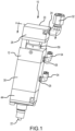
- the fluid dispenser 10 includes a dispenser housing 12, a displacement chamber 14 defined within the dispenser housing 12, a dispensing luer 16 for dispensing the small doses of fluid, and a zero displacement sealing device (a diaphragm assembly) 18 arranged within the dispenser housing 12 for allowing the fluid dispenser 10 to dispense consistent and precise volume of fluid, as will be described in greater detail below.
- Directional terms, such as upward and downward are referenced to an orientation in which the dispensing luer 16 of the fluid dispenser 10 is pointing downward.
- the present invention is not thereby limited to use in any particular orientation.
- the dispenser housing 12 is elongate and extends between a first end 20 and a second end 22.
- the first and second ends 20, 22 are for receiving the fluid and for dispensing the fluid, respectively, as will be described in greater detail below.
- a fluid input fitting hole 24 and a plurality of air fitting holes 26 are defined in a first end portion 28 of the dispenser housing 12 and in a middle portion 30 of the dispenser housing 12, respectively.
- a part of a fluid input fitting 32 and a part of an air fitting 34 are inserted and attached through the fluid input fitting hole 24 and the air fitting hole 26, respectively.
- the fluid input fitting 32 provides a fluid path between a fluid reservoir (not shown) and the fluid dispenser 10, whereas air is supplied to the fluid dispenser 10 through the plurality of air fittings 26 with an air pressure, preferably, 413,685 kPa.
- the fluid is pressurized, preferably, between 34,4738 kPa and 344,738 kPa .
- a receiving chamber 36 and a dispensing chamber 38 are defined within the fluid dispenser 10 for containing the fluid to be dispensed.
- the receiving chamber 36 is defined adjacent the first end 20 of the dispenser housing 12
- the dispensing chamber 38 is defined adjacent the second end 22 of the dispenser housing 12.
- the dispenser housing 12 further defines a fluid flow path from the receiving chamber 36 to the dispensing chamber 38 for the fluid to travel therebetween. More specifically, a fluid tube 40 is disposed within the dispenser housing 12 to accommodate the fluid flow path therewithin.
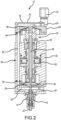
- the fluid tube 40 is configured and arranged such that end portions 42 of the fluid tube 40 are horizontally disposed within the first end portion 28 and second end portion 44 of the dispenser housing 12, and a middle portion 46 of the fluid tube 40 is vertically disposed within the dispenser housing 12, with each end of the middle portion 46 of the fluid tube 40 connecting to each end of the end portions 42 of the fluid tube 40, as show in Figures 2 and 3 .
- the fluid then travels along the fluid flow path via the fluid tube 40 and fills the receiving chamber 36, the dispensing chamber 38, and the displacement chamber 14.
- the diaphragm assembly 18 is arranged within the dispenser housing 12 and acts as a device for volumetric displacement of the fluid contained within the receiving chamber 36 and the dispensing chamber 38.
- the diaphragm assembly 18 includes substantially identical first and second diaphragms 48, 50, with the first diaphragm 48 arranged within the receiving chamber 36 and the second diaphragm 50 arranged within the dispensing chamber 38. This arrangement allows a lower end of the receiving chamber 36 and an upper end of the dispensing chamber 38 to be defined by the first diaphragm 48 and the second diaphragm 50, respectively.
- the first diaphragm 48 is operably connected to the second diaphragm 50 for movement between a first/open position ( Figure 2 ) and a second/closed position ( Figure 3 ).
- the first and second diaphragms 48, 50 are connected to each end of a connecting rod 56, respectively, which is disposed vertically within the dispenser housing 12 and bolted to an actuator 58.
- the length of an actuator stroke may be adjusted with a stroke adjustor 59.
- the movement of the first and second diaphragms 48, 50 will be described in greater detail below.
- the fluid dispenser 10 further includes a displacement rod 60, which is disposed within the dispenser housing 12 and is positioned above the displacement chamber 14.
- the displacement chamber 14 is defined adjacent the second end 22 of the dispenser housing 12 and is in communication with the dispensing chamber 38.
- the fluid dispenser 10 is made of one or more materials having suitable properties for a desired application, including strength, weight, rigidity, etc. Steel is preferred for the fluid dispenser 10.
- the receiving and dispensing chambers are configured and dimensioned such that they are substantially identical.
- the diaphragm assembly 18 In operation of the fluid dispenser 10, before the fluid dispenser 10 dispenses the fluid, the diaphragm assembly 18 is initially in the first/open position, as shown in Figure 2 . In this position, the first diaphragm 48 and the second diaphragm 50 are fully extended and retracted, respectively, such that the fluid to be dispensed is contained within the dispensing chamber 38.
- the actuator 58 moves the connecting rod 56 linearly downward to reverse the position of each of the first and second diaphragms 48, 50 such that the diaphragm assembly 18 transitions to the second/closed position, as shown in Figure 3 .
- the first diaphragm 48 and the second diaphragm 50 are fully retracted and extended, respectively, such that the receiving chamber 36 is filled with the fluid to be dispensed, and the fluid in the dispensing chamber 38 is moved to the displacement chamber 14 by the force exerted by the extension of the second diaphragm 50.
- the fluid volume in the dispensing chamber 38 decreases, and the fluid volume in the receiving chamber 36 increases. Since the receiving and dispensing chambers 36, 38 are substantially identical, when the fluid dispenser 10 dispenses the fluid, the volumetric displacement of the fluid in the receiving chamber 36 is equal to the volumetric displacement of the fluid in the dispensing chamber 38.
- the actuator 58 also moves the displacement rod 60 downward, forcing the displacement rod 60 to be placed within the displacement chamber 14.
- the displacement rod 60 pushes the fluid in the displacement chamber 14 to the dispensing luer 16 which is in communication with the displacement chamber 14.
- the dispensing luer 16 then dispenses the fluid from the fluid dispenser 10.
- the diaphragm assembly 18 provides a higher energy transfer from the actuator 58 because the first and second diaphragms 48, 50 are unitized.
- This unitized sealing method creates a precise volume of the fluid to be dispensed and also creates a force balance between the first and second diaphragms 48, 50 as they move together.
- the force require to move the first and second diaphragms 48, 50 approaches zero as the projected area of one diaphragm increases and the other diaphragm decreases.
- the actuator 58 moves the diaphragm assembly 18 linearly upward and transitions the diaphragm assembly 18 back to the first position.
- the first diaphragm 48 and the second diaphragm 50 are fully extended and retracted, respectively.
- the force exerted by the extension of the first diaphragm 48 allows the fluid in the receiving chamber 36 to move to the dispensing chamber 38 along the fluid flow path for dispensing.
- a fluid dispenser according to the present invention dispenses small doses of fluid while enhancing precision of fluid volume to be dispensed and longevity of the fluid dispenser.
Landscapes
- Engineering & Computer Science (AREA)
- Mechanical Engineering (AREA)
- General Engineering & Computer Science (AREA)
- Physics & Mathematics (AREA)
- Fluid Mechanics (AREA)
- General Physics & Mathematics (AREA)
- Chemical & Material Sciences (AREA)
- Organic Chemistry (AREA)
- Coating Apparatus (AREA)
- Reciprocating Pumps (AREA)
- Nozzles (AREA)
- Devices For Dispensing Beverages (AREA)
Claims (15)
- Distributeur de fluide (10) destiné à distribuer des petites doses de fluide comprenant :un boîtier de distributeur (12), le boîtier de distributeur (12) ayant une première extrémité (20) pour recevoir le fluide et une seconde extrémité (22) pour distribuer le fluide, le boîtier de distributeur (12) comprenant une chambre de réception (36) adjacente à la première extrémité (20) et une chambre de distribution (38) adjacente à la seconde extrémité (22), le boîtier de distributeur (12) définissant une voie d'écoulement de fluide depuis la chambre de réception (36) vers la chambre de distribution (38) ;un ensemble de diaphragmes (18) comportant :un premier diaphragme (48) à l'intérieur de la chambre de réception (36) et un second diaphragme (50) à l'intérieur de la chambre de distribution (38), le premier diaphragme (48) étant relié de manière fonctionnelle au second diaphragme (50) pour un mouvement entre une première position et une seconde position ;une chambre de déplacement (14) adjacente à la seconde extrémité (22) du boîtier de distributeur (12) en communication avec la chambre de distribution (38), l'ensemble de diaphragmes (18) étant mobile entre la première position dans laquelle le premier diaphragme (48) provoque le mouvement du fluide depuis la chambre de réception (36) vers la chambre de distribution (38) le long de la voie d'écoulement de fluide et la seconde position dans laquelle le second diaphragme (50) provoque le mouvement du fluide depuis la chambre de distribution (38) vers la chambre de déplacement (14) ; etun raccord Luer de distribution (16) en communication avec la chambre de déplacement (14) pour distribuer les petites doses de fluide lors du mouvement de l'ensemble de diaphragmes (18) vers la seconde position ;dans lequel l'ensemble de diaphragmes (18) comporte en outre une bielle (56), et dans lequel le premier diaphragme (48) et le second diaphragme (50) sont fixés à chaque extrémité de la bielle (56), respectivement.
- Distributeur de fluide (10) selon la revendication 1, dans lequel, dans la première position, le premier diaphragme (48) et le second diaphragme (50) sont complètement étendu et rétracté, respectivement.
- Distributeur de fluide (10) selon la revendication 1, dans lequel, dans la seconde position, le premier diaphragme (48) et le second diaphragme (50) sont complètement rétracté et étendu, respectivement.
- Distributeur de fluide (10) selon la revendication 1, dans lequel le distributeur de fluide comprend en outre un tube pour fluide (40) pour accueillir la voie d'écoulement de fluide.
- Distributeur de fluide (10) selon la revendication 4, dans lequel le tube pour fluide (40) est conçu et agencé de telle sorte que les parties d'extrémité (42) du tube pour fluide (40) sont disposées horizontalement à l'intérieur d'une première partie d'extrémité (28) et d'une seconde partie d'extrémité (44) du boîtier de distributeur (12), et une partie centrale (46) du tube pour fluide (40) est disposée verticalement à l'intérieur du boîtier de distributeur (12), chaque extrémité de la partie centrale (46) du tube pour fluide (40) étant reliée à chaque extrémité des parties d'extrémité (42) du tube pour fluide (40).
- Distributeur de fluide (10) selon la revendication 5, dans lequel, lorsque le fluide entre par la première extrémité (28) du boîtier de distributeur (12), le fluide traverse le tube pour fluide (40) et remplit la chambre de réception (36), la chambre de distribution (38) et la chambre de déplacement (14).
- Distributeur de fluide (10) selon la revendication 1, dans lequel le distributeur de fluide (10) comprend en outre une tige de déplacement (60), qui est disposée à l'intérieur du boîtier de distributeur (12) et positionnée au-dessus de la chambre de déplacement (14).
- Distributeur de fluide (10) selon la revendication 2, dans lequel le distributeur de fluide (10) comprend en outre un actionneur (58) disposé à l'intérieur du boîtier de distributeur (12).
- Distributeur de fluide (10) selon la revendication 8, dans lequel, lorsque le distributeur de fluide (10) distribue une dose de fluide, l'actionneur (58) provoque le mouvement de la tige de déplacement (60) dans la chambre de déplacement (14), amenant le fluide à l'intérieur de la chambre de déplacement (14) à sortir du distributeur de fluide (10).
- Distributeur de fluide (10) selon la revendication 1, dans lequel un trou pour raccord d'entrée (24) est défini au niveau de la première extrémité (28) du boîtier de distributeur (12), à travers lequel une partie d'un raccord d'entrée (32) est insérée et fixée.
- Distributeur de fluide (10) selon la revendication 1, dans lequel une pluralité de trous pour raccords d'air (26) sont définis sur le boîtier de distributeur (12), à travers lesquels une partie d'un raccord d'air (34) est insérée pour être fixée.
- Distributeur de fluide (10) selon la revendication 9, dans lequel la bielle (56) est boulonnée à l'actionneur (58).
- Distributeur de fluide selon la revendication 1, dans lequel le fluide est un adhésif ou un cyanoacrylate ou est durcissable en anaérobiose.
- Distributeur de fluide selon la revendication 1, dans lequel les premier et second diaphragmes sont sensiblement identiques.
- Distributeur de fluide (10) selon la revendication 1, dans lequel les chambres de réception et de distribution sont sensiblement identiques.
Applications Claiming Priority (2)
| Application Number | Priority Date | Filing Date | Title |
|---|---|---|---|
| US201762551487P | 2017-08-29 | 2017-08-29 | |
| PCT/US2018/048543 WO2019046425A1 (fr) | 2017-08-29 | 2018-08-29 | Distributeur de fluide avec dispositif d'étanchéité à déplacement nul |
Publications (3)
| Publication Number | Publication Date |
|---|---|
| EP3676021A1 EP3676021A1 (fr) | 2020-07-08 |
| EP3676021A4 EP3676021A4 (fr) | 2021-06-09 |
| EP3676021B1 true EP3676021B1 (fr) | 2024-07-17 |
Family
ID=65525971
Family Applications (1)
| Application Number | Title | Priority Date | Filing Date |
|---|---|---|---|
| EP18851920.1A Active EP3676021B1 (fr) | 2017-08-29 | 2018-08-29 | Distributeur de fluide avec dispositif d'étanchéité à déplacement nul |
Country Status (6)
| Country | Link |
|---|---|
| US (1) | US11173514B2 (fr) |
| EP (1) | EP3676021B1 (fr) |
| JP (1) | JP7541919B2 (fr) |
| KR (1) | KR102525478B1 (fr) |
| CN (1) | CN111065466B (fr) |
| WO (1) | WO2019046425A1 (fr) |
Families Citing this family (1)
| Publication number | Priority date | Publication date | Assignee | Title |
|---|---|---|---|---|
| DE102018131567A1 (de) * | 2018-12-10 | 2020-06-10 | Vermes Microdispensing GmbH | Dosiersystem und Verfahren zur Steuerung eines Dosiersystems |
Family Cites Families (26)
| Publication number | Priority date | Publication date | Assignee | Title |
|---|---|---|---|---|
| US3895748A (en) * | 1974-04-03 | 1975-07-22 | George R Klingenberg | No drip suck back units for glue or other liquids either separately installed with or incorporated into no drip suck back liquid applying and control apparatus |
| AT372417B (de) * | 1980-08-21 | 1983-10-10 | Zimmer Johannes Gmbh | Spritzduese |
| JPS60219791A (ja) * | 1984-04-16 | 1985-11-02 | 松下電器産業株式会社 | 厚膜回路の形成装置 |
| JPH0331876Y2 (fr) * | 1986-10-29 | 1991-07-05 | ||
| JPH0422856Y2 (fr) * | 1986-11-05 | 1992-05-26 | ||
| CH675216A5 (fr) * | 1987-11-30 | 1990-09-14 | Alphasem Ag | |
| US5467899A (en) * | 1994-02-08 | 1995-11-21 | Liquid Control Corporation | Dispensing device for flowable materials |
| JPH09136048A (ja) * | 1995-11-15 | 1997-05-27 | Trinity Ind Corp | 塗料供給装置 |
| US6196521B1 (en) * | 1998-08-18 | 2001-03-06 | Precision Valve & Automation, Inc. | Fluid dispensing valve and method |
| JP3142271B2 (ja) | 1999-05-10 | 2001-03-07 | 日東商事株式会社 | 溶液噴射装置 |
| US6478547B1 (en) * | 1999-10-18 | 2002-11-12 | Integrated Designs L.P. | Method and apparatus for dispensing fluids |
| DE10229418A1 (de) * | 2002-06-29 | 2004-01-29 | Robert Bosch Gmbh | Einrichtung zur Dämpfung des Nadelhubes an Kraftstoffinjektoren |
| JP4454350B2 (ja) * | 2004-03-23 | 2010-04-21 | 株式会社コガネイ | 薬液供給装置 |
| RU2417847C1 (ru) * | 2009-10-13 | 2011-05-10 | Максим Юрьевич Парамонов | Форсунка для нанесения клея или иной жидкости на поверхность объекта |
| US8757511B2 (en) * | 2010-01-11 | 2014-06-24 | AdvanJet | Viscous non-contact jetting method and apparatus |
| WO2012027248A1 (fr) * | 2010-08-26 | 2012-03-01 | Henkel Corporation | Distributeur pneumatique à double cartouche intégrant un robinet anti-goutte amovible permettant une distribution précise |
| US9346075B2 (en) * | 2011-08-26 | 2016-05-24 | Nordson Corporation | Modular jetting devices |
| US9254642B2 (en) * | 2012-01-19 | 2016-02-09 | AdvanJet | Control method and apparatus for dispensing high-quality drops of high-viscosity material |
| CN203245086U (zh) * | 2012-04-11 | 2013-10-23 | 吉林大学 | 一种压电晶片控制型非接触点胶装置 |
| FR2994536B1 (fr) * | 2012-08-16 | 2015-09-18 | Capsum | Element de delivrance d'une composition fluide, dispositif de distribution et procede associes |
| DE102012024710A1 (de) * | 2012-11-07 | 2014-05-08 | Heraeus Medical Gmbh | Vorrichtung zum Mischen und Austragen einer pastösen Masse |
| US20140263403A1 (en) * | 2013-03-15 | 2014-09-18 | Nordson Corporation | Liquid Dispensing Syringe |
| FR3020052B1 (fr) * | 2014-04-16 | 2017-03-10 | Aptar France Sas | Distributeur de produit fluide. |
| FR3023269B1 (fr) * | 2014-07-04 | 2017-08-25 | Aptar France Sas | Distributeur de produit fluide. |
| FR3047186B1 (fr) * | 2016-02-01 | 2020-02-14 | Albea Lacrost | Dispositif de purge d'air pour distributeur de produit liquide sans reprise d'air |
| NL2021163B1 (en) * | 2018-06-21 | 2020-01-06 | Suss Microtec Lithography Gmbh | Dispensing nozzle for a Coater |
-
2018
- 2018-08-29 CN CN201880055455.XA patent/CN111065466B/zh active Active
- 2018-08-29 WO PCT/US2018/048543 patent/WO2019046425A1/fr not_active Ceased
- 2018-08-29 KR KR1020207006838A patent/KR102525478B1/ko active Active
- 2018-08-29 EP EP18851920.1A patent/EP3676021B1/fr active Active
- 2018-08-29 JP JP2020512451A patent/JP7541919B2/ja active Active
-
2020
- 2020-02-24 US US16/798,514 patent/US11173514B2/en active Active
Also Published As
| Publication number | Publication date |
|---|---|
| EP3676021A4 (fr) | 2021-06-09 |
| JP2020532415A (ja) | 2020-11-12 |
| EP3676021A1 (fr) | 2020-07-08 |
| CN111065466B (zh) | 2022-05-10 |
| US20200188950A1 (en) | 2020-06-18 |
| US11173514B2 (en) | 2021-11-16 |
| KR20200047566A (ko) | 2020-05-07 |
| CN111065466A (zh) | 2020-04-24 |
| KR102525478B1 (ko) | 2023-04-26 |
| WO2019046425A1 (fr) | 2019-03-07 |
| JP7541919B2 (ja) | 2024-08-29 |
Similar Documents
| Publication | Publication Date | Title |
|---|---|---|
| US9457372B2 (en) | Viscous non-contact jetting method and apparatus | |
| RU2573018C2 (ru) | Жидкостный дозатор | |
| US7980425B2 (en) | Metering pump for dispensing liquid | |
| US4245963A (en) | Pump | |
| IE52625B1 (en) | Method of and device for dispensing viscous concentrates of variable viscosity in accurately metered quantities of variable volume | |
| EP0581817B1 (fr) | Vaporisateur anesthesique | |
| EP3676021B1 (fr) | Distributeur de fluide avec dispositif d'étanchéité à déplacement nul | |
| CN107352152A (zh) | 液压泵 | |
| JP2015522736A (ja) | 往復容量型ポンプ用の直接容積制御装置(dvcd) | |
| US10982986B2 (en) | Micrometering pump | |
| KR20210060891A (ko) | 일정한 유량을 지속하는 소형 기계식 댐퍼 | |
| CN107206196A (zh) | 小型分配泵中的剂量传送 | |
| CN101600502B (zh) | 用于向充气的舱室内配量液体的装置和方法 | |
| CN107076126B (zh) | 用于流体产品的容积泵和泵送组以及使用其的方法 | |
| US6004117A (en) | Displacement pump | |
| US4281687A (en) | Fluid storage device | |
| EP3205878A1 (fr) | Dispositif de mesure pour distribution d'une substance liquide ou visqueuse | |
| JP7469752B2 (ja) | 計量ポンプ | |
| EP4534122A1 (fr) | Dispositif de dosage de fluide médical | |
| CZ869488A3 (cs) | Dávkovači zařízení malých objemů kapalin o nízké viskositě | |
| TH65797A (th) | ปั๊มจัดจ่ายรายครั้งสำหรับจัดจ่ายสารสองสาร หรือมากกว่าสองสาร | |
| TH32371B (th) | ปั๊มจัดจ่ายรายครั้งสำหรับจัดจ่ายสารสองสาร หรือมากกว่าสองสาร | |
| PL225713B1 (pl) | Urządzenie dozujące | |
| CS217119B1 (cs) | Pístové dávkovači čerpadlo s magneticky ovládaným pístem |
Legal Events
| Date | Code | Title | Description |
|---|---|---|---|
| STAA | Information on the status of an ep patent application or granted ep patent |
Free format text: STATUS: THE INTERNATIONAL PUBLICATION HAS BEEN MADE |
|
| PUAI | Public reference made under article 153(3) epc to a published international application that has entered the european phase |
Free format text: ORIGINAL CODE: 0009012 |
|
| STAA | Information on the status of an ep patent application or granted ep patent |
Free format text: STATUS: REQUEST FOR EXAMINATION WAS MADE |
|
| 17P | Request for examination filed |
Effective date: 20200228 |
|
| AK | Designated contracting states |
Kind code of ref document: A1 Designated state(s): AL AT BE BG CH CY CZ DE DK EE ES FI FR GB GR HR HU IE IS IT LI LT LU LV MC MK MT NL NO PL PT RO RS SE SI SK SM TR |
|
| AX | Request for extension of the european patent |
Extension state: BA ME |
|
| DAV | Request for validation of the european patent (deleted) | ||
| DAX | Request for extension of the european patent (deleted) | ||
| REG | Reference to a national code |
Ref country code: DE Free format text: PREVIOUS MAIN CLASS: B05C0017015000 Ref country code: DE Ref legal event code: R079 Ref document number: 602018071983 Country of ref document: DE Free format text: PREVIOUS MAIN CLASS: B05C0017015000 Ipc: B05C0005020000 |
|
| A4 | Supplementary search report drawn up and despatched |
Effective date: 20210511 |
|
| RIC1 | Information provided on ipc code assigned before grant |
Ipc: B05C 5/02 20060101AFI20210504BHEP |
|
| RAP1 | Party data changed (applicant data changed or rights of an application transferred) |
Owner name: HENKEL AG & CO. KGAA |
|
| P01 | Opt-out of the competence of the unified patent court (upc) registered |
Effective date: 20230531 |
|
| GRAP | Despatch of communication of intention to grant a patent |
Free format text: ORIGINAL CODE: EPIDOSNIGR1 |
|
| STAA | Information on the status of an ep patent application or granted ep patent |
Free format text: STATUS: GRANT OF PATENT IS INTENDED |
|
| INTG | Intention to grant announced |
Effective date: 20231219 |
|
| GRAJ | Information related to disapproval of communication of intention to grant by the applicant or resumption of examination proceedings by the epo deleted |
Free format text: ORIGINAL CODE: EPIDOSDIGR1 |
|
| STAA | Information on the status of an ep patent application or granted ep patent |
Free format text: STATUS: REQUEST FOR EXAMINATION WAS MADE |
|
| INTC | Intention to grant announced (deleted) | ||
| GRAP | Despatch of communication of intention to grant a patent |
Free format text: ORIGINAL CODE: EPIDOSNIGR1 |
|
| STAA | Information on the status of an ep patent application or granted ep patent |
Free format text: STATUS: GRANT OF PATENT IS INTENDED |
|
| INTG | Intention to grant announced |
Effective date: 20240416 |
|
| GRAS | Grant fee paid |
Free format text: ORIGINAL CODE: EPIDOSNIGR3 |
|
| GRAA | (expected) grant |
Free format text: ORIGINAL CODE: 0009210 |
|
| STAA | Information on the status of an ep patent application or granted ep patent |
Free format text: STATUS: THE PATENT HAS BEEN GRANTED |
|
| AK | Designated contracting states |
Kind code of ref document: B1 Designated state(s): AL AT BE BG CH CY CZ DE DK EE ES FI FR GB GR HR HU IE IS IT LI LT LU LV MC MK MT NL NO PL PT RO RS SE SI SK SM TR |
|
| REG | Reference to a national code |
Ref country code: CH Ref legal event code: EP |
|
| REG | Reference to a national code |
Ref country code: DE Ref legal event code: R096 Ref document number: 602018071983 Country of ref document: DE |
|
| REG | Reference to a national code |
Ref country code: IE Ref legal event code: FG4D |
|
| REG | Reference to a national code |
Ref country code: LT Ref legal event code: MG9D |
|
| REG | Reference to a national code |
Ref country code: NL Ref legal event code: MP Effective date: 20240717 |
|
| PG25 | Lapsed in a contracting state [announced via postgrant information from national office to epo] |
Ref country code: PT Free format text: LAPSE BECAUSE OF FAILURE TO SUBMIT A TRANSLATION OF THE DESCRIPTION OR TO PAY THE FEE WITHIN THE PRESCRIBED TIME-LIMIT Effective date: 20241118 |
|
| REG | Reference to a national code |
Ref country code: AT Ref legal event code: MK05 Ref document number: 1703656 Country of ref document: AT Kind code of ref document: T Effective date: 20240717 |
|
| PG25 | Lapsed in a contracting state [announced via postgrant information from national office to epo] |
Ref country code: NL Free format text: LAPSE BECAUSE OF FAILURE TO SUBMIT A TRANSLATION OF THE DESCRIPTION OR TO PAY THE FEE WITHIN THE PRESCRIBED TIME-LIMIT Effective date: 20240717 |
|
| PG25 | Lapsed in a contracting state [announced via postgrant information from national office to epo] |
Ref country code: PT Free format text: LAPSE BECAUSE OF FAILURE TO SUBMIT A TRANSLATION OF THE DESCRIPTION OR TO PAY THE FEE WITHIN THE PRESCRIBED TIME-LIMIT Effective date: 20241118 Ref country code: NL Free format text: LAPSE BECAUSE OF FAILURE TO SUBMIT A TRANSLATION OF THE DESCRIPTION OR TO PAY THE FEE WITHIN THE PRESCRIBED TIME-LIMIT Effective date: 20240717 |
|
| PG25 | Lapsed in a contracting state [announced via postgrant information from national office to epo] |
Ref country code: NO Free format text: LAPSE BECAUSE OF FAILURE TO SUBMIT A TRANSLATION OF THE DESCRIPTION OR TO PAY THE FEE WITHIN THE PRESCRIBED TIME-LIMIT Effective date: 20241017 |
|
| PG25 | Lapsed in a contracting state [announced via postgrant information from national office to epo] |
Ref country code: GR Free format text: LAPSE BECAUSE OF FAILURE TO SUBMIT A TRANSLATION OF THE DESCRIPTION OR TO PAY THE FEE WITHIN THE PRESCRIBED TIME-LIMIT Effective date: 20241018 Ref country code: FI Free format text: LAPSE BECAUSE OF FAILURE TO SUBMIT A TRANSLATION OF THE DESCRIPTION OR TO PAY THE FEE WITHIN THE PRESCRIBED TIME-LIMIT Effective date: 20240717 Ref country code: PL Free format text: LAPSE BECAUSE OF FAILURE TO SUBMIT A TRANSLATION OF THE DESCRIPTION OR TO PAY THE FEE WITHIN THE PRESCRIBED TIME-LIMIT Effective date: 20240717 |
|
| PG25 | Lapsed in a contracting state [announced via postgrant information from national office to epo] |
Ref country code: BG Free format text: LAPSE BECAUSE OF FAILURE TO SUBMIT A TRANSLATION OF THE DESCRIPTION OR TO PAY THE FEE WITHIN THE PRESCRIBED TIME-LIMIT Effective date: 20240717 |
|
| PG25 | Lapsed in a contracting state [announced via postgrant information from national office to epo] |
Ref country code: LV Free format text: LAPSE BECAUSE OF FAILURE TO SUBMIT A TRANSLATION OF THE DESCRIPTION OR TO PAY THE FEE WITHIN THE PRESCRIBED TIME-LIMIT Effective date: 20240717 |
|
| PG25 | Lapsed in a contracting state [announced via postgrant information from national office to epo] |
Ref country code: IS Free format text: LAPSE BECAUSE OF FAILURE TO SUBMIT A TRANSLATION OF THE DESCRIPTION OR TO PAY THE FEE WITHIN THE PRESCRIBED TIME-LIMIT Effective date: 20241117 Ref country code: AT Free format text: LAPSE BECAUSE OF FAILURE TO SUBMIT A TRANSLATION OF THE DESCRIPTION OR TO PAY THE FEE WITHIN THE PRESCRIBED TIME-LIMIT Effective date: 20240717 |
|
| PG25 | Lapsed in a contracting state [announced via postgrant information from national office to epo] |
Ref country code: HR Free format text: LAPSE BECAUSE OF FAILURE TO SUBMIT A TRANSLATION OF THE DESCRIPTION OR TO PAY THE FEE WITHIN THE PRESCRIBED TIME-LIMIT Effective date: 20240717 |
|
| PG25 | Lapsed in a contracting state [announced via postgrant information from national office to epo] |
Ref country code: ES Free format text: LAPSE BECAUSE OF FAILURE TO SUBMIT A TRANSLATION OF THE DESCRIPTION OR TO PAY THE FEE WITHIN THE PRESCRIBED TIME-LIMIT Effective date: 20240717 Ref country code: RS Free format text: LAPSE BECAUSE OF FAILURE TO SUBMIT A TRANSLATION OF THE DESCRIPTION OR TO PAY THE FEE WITHIN THE PRESCRIBED TIME-LIMIT Effective date: 20241017 |
|
| PG25 | Lapsed in a contracting state [announced via postgrant information from national office to epo] |
Ref country code: RS Free format text: LAPSE BECAUSE OF FAILURE TO SUBMIT A TRANSLATION OF THE DESCRIPTION OR TO PAY THE FEE WITHIN THE PRESCRIBED TIME-LIMIT Effective date: 20241017 Ref country code: PL Free format text: LAPSE BECAUSE OF FAILURE TO SUBMIT A TRANSLATION OF THE DESCRIPTION OR TO PAY THE FEE WITHIN THE PRESCRIBED TIME-LIMIT Effective date: 20240717 Ref country code: NO Free format text: LAPSE BECAUSE OF FAILURE TO SUBMIT A TRANSLATION OF THE DESCRIPTION OR TO PAY THE FEE WITHIN THE PRESCRIBED TIME-LIMIT Effective date: 20241017 Ref country code: LV Free format text: LAPSE BECAUSE OF FAILURE TO SUBMIT A TRANSLATION OF THE DESCRIPTION OR TO PAY THE FEE WITHIN THE PRESCRIBED TIME-LIMIT Effective date: 20240717 Ref country code: IS Free format text: LAPSE BECAUSE OF FAILURE TO SUBMIT A TRANSLATION OF THE DESCRIPTION OR TO PAY THE FEE WITHIN THE PRESCRIBED TIME-LIMIT Effective date: 20241117 Ref country code: HR Free format text: LAPSE BECAUSE OF FAILURE TO SUBMIT A TRANSLATION OF THE DESCRIPTION OR TO PAY THE FEE WITHIN THE PRESCRIBED TIME-LIMIT Effective date: 20240717 Ref country code: GR Free format text: LAPSE BECAUSE OF FAILURE TO SUBMIT A TRANSLATION OF THE DESCRIPTION OR TO PAY THE FEE WITHIN THE PRESCRIBED TIME-LIMIT Effective date: 20241018 Ref country code: FI Free format text: LAPSE BECAUSE OF FAILURE TO SUBMIT A TRANSLATION OF THE DESCRIPTION OR TO PAY THE FEE WITHIN THE PRESCRIBED TIME-LIMIT Effective date: 20240717 Ref country code: ES Free format text: LAPSE BECAUSE OF FAILURE TO SUBMIT A TRANSLATION OF THE DESCRIPTION OR TO PAY THE FEE WITHIN THE PRESCRIBED TIME-LIMIT Effective date: 20240717 Ref country code: BG Free format text: LAPSE BECAUSE OF FAILURE TO SUBMIT A TRANSLATION OF THE DESCRIPTION OR TO PAY THE FEE WITHIN THE PRESCRIBED TIME-LIMIT Effective date: 20240717 Ref country code: AT Free format text: LAPSE BECAUSE OF FAILURE TO SUBMIT A TRANSLATION OF THE DESCRIPTION OR TO PAY THE FEE WITHIN THE PRESCRIBED TIME-LIMIT Effective date: 20240717 |
|
| REG | Reference to a national code |
Ref country code: CH Ref legal event code: PL |
|
| PG25 | Lapsed in a contracting state [announced via postgrant information from national office to epo] |
Ref country code: DK Free format text: LAPSE BECAUSE OF FAILURE TO SUBMIT A TRANSLATION OF THE DESCRIPTION OR TO PAY THE FEE WITHIN THE PRESCRIBED TIME-LIMIT Effective date: 20240717 Ref country code: RO Free format text: LAPSE BECAUSE OF FAILURE TO SUBMIT A TRANSLATION OF THE DESCRIPTION OR TO PAY THE FEE WITHIN THE PRESCRIBED TIME-LIMIT Effective date: 20240717 Ref country code: SM Free format text: LAPSE BECAUSE OF FAILURE TO SUBMIT A TRANSLATION OF THE DESCRIPTION OR TO PAY THE FEE WITHIN THE PRESCRIBED TIME-LIMIT Effective date: 20240717 |
|
| PG25 | Lapsed in a contracting state [announced via postgrant information from national office to epo] |
Ref country code: LU Free format text: LAPSE BECAUSE OF NON-PAYMENT OF DUE FEES Effective date: 20240829 |
|
| REG | Reference to a national code |
Ref country code: DE Ref legal event code: R097 Ref document number: 602018071983 Country of ref document: DE |
|
| PG25 | Lapsed in a contracting state [announced via postgrant information from national office to epo] |
Ref country code: CH Free format text: LAPSE BECAUSE OF NON-PAYMENT OF DUE FEES Effective date: 20240831 Ref country code: MC Free format text: LAPSE BECAUSE OF FAILURE TO SUBMIT A TRANSLATION OF THE DESCRIPTION OR TO PAY THE FEE WITHIN THE PRESCRIBED TIME-LIMIT Effective date: 20240717 Ref country code: EE Free format text: LAPSE BECAUSE OF FAILURE TO SUBMIT A TRANSLATION OF THE DESCRIPTION OR TO PAY THE FEE WITHIN THE PRESCRIBED TIME-LIMIT Effective date: 20240717 |
|
| PG25 | Lapsed in a contracting state [announced via postgrant information from national office to epo] |
Ref country code: CZ Free format text: LAPSE BECAUSE OF FAILURE TO SUBMIT A TRANSLATION OF THE DESCRIPTION OR TO PAY THE FEE WITHIN THE PRESCRIBED TIME-LIMIT Effective date: 20240717 |
|
| PG25 | Lapsed in a contracting state [announced via postgrant information from national office to epo] |
Ref country code: SK Free format text: LAPSE BECAUSE OF FAILURE TO SUBMIT A TRANSLATION OF THE DESCRIPTION OR TO PAY THE FEE WITHIN THE PRESCRIBED TIME-LIMIT Effective date: 20240717 |
|
| PLBE | No opposition filed within time limit |
Free format text: ORIGINAL CODE: 0009261 |
|
| STAA | Information on the status of an ep patent application or granted ep patent |
Free format text: STATUS: NO OPPOSITION FILED WITHIN TIME LIMIT |
|
| 26N | No opposition filed |
Effective date: 20250422 |
|
| REG | Reference to a national code |
Ref country code: BE Ref legal event code: MM Effective date: 20240831 |
|
| PG25 | Lapsed in a contracting state [announced via postgrant information from national office to epo] |
Ref country code: BE Free format text: LAPSE BECAUSE OF NON-PAYMENT OF DUE FEES Effective date: 20240831 |
|
| PG25 | Lapsed in a contracting state [announced via postgrant information from national office to epo] |
Ref country code: IE Free format text: LAPSE BECAUSE OF NON-PAYMENT OF DUE FEES Effective date: 20240829 |
|
| PG25 | Lapsed in a contracting state [announced via postgrant information from national office to epo] |
Ref country code: SE Free format text: LAPSE BECAUSE OF FAILURE TO SUBMIT A TRANSLATION OF THE DESCRIPTION OR TO PAY THE FEE WITHIN THE PRESCRIBED TIME-LIMIT Effective date: 20240717 |
|
| PGFP | Annual fee paid to national office [announced via postgrant information from national office to epo] |
Ref country code: DE Payment date: 20250820 Year of fee payment: 8 |
|
| PGFP | Annual fee paid to national office [announced via postgrant information from national office to epo] |
Ref country code: GB Payment date: 20250820 Year of fee payment: 8 |
|
| PGFP | Annual fee paid to national office [announced via postgrant information from national office to epo] |
Ref country code: FR Payment date: 20250828 Year of fee payment: 8 |
|
| PG25 | Lapsed in a contracting state [announced via postgrant information from national office to epo] |
Ref country code: IT Free format text: LAPSE BECAUSE OF NON-PAYMENT OF DUE FEES Effective date: 20240829 |
|
| PG25 | Lapsed in a contracting state [announced via postgrant information from national office to epo] |
Ref country code: CY Free format text: LAPSE BECAUSE OF FAILURE TO SUBMIT A TRANSLATION OF THE DESCRIPTION OR TO PAY THE FEE WITHIN THE PRESCRIBED TIME-LIMIT; INVALID AB INITIO Effective date: 20180829 |
|
| PG25 | Lapsed in a contracting state [announced via postgrant information from national office to epo] |
Ref country code: HU Free format text: LAPSE BECAUSE OF FAILURE TO SUBMIT A TRANSLATION OF THE DESCRIPTION OR TO PAY THE FEE WITHIN THE PRESCRIBED TIME-LIMIT; INVALID AB INITIO Effective date: 20180829 |
|
| PG25 | Lapsed in a contracting state [announced via postgrant information from national office to epo] |
Ref country code: IT Free format text: LAPSE BECAUSE OF NON-PAYMENT OF DUE FEES Effective date: 20240829 |
|
| PGFP | Annual fee paid to national office [announced via postgrant information from national office to epo] |
Ref country code: IT Payment date: 20250825 Year of fee payment: 8 |
|
| PGRI | Patent reinstated in contracting state [announced from national office to epo] |
Ref country code: IT Effective date: 20241231 |