EP3676408B1 - Procédé pour chauffer une pièce métallique à une température finale et four à rouleaux correspondant - Google Patents
Procédé pour chauffer une pièce métallique à une température finale et four à rouleaux correspondant Download PDFInfo
- Publication number
- EP3676408B1 EP3676408B1 EP18765599.8A EP18765599A EP3676408B1 EP 3676408 B1 EP3676408 B1 EP 3676408B1 EP 18765599 A EP18765599 A EP 18765599A EP 3676408 B1 EP3676408 B1 EP 3676408B1
- Authority
- EP
- European Patent Office
- Prior art keywords
- temperature
- zone
- heating
- plateau
- peak
- Prior art date
- Legal status (The legal status is an assumption and is not a legal conclusion. Google has not performed a legal analysis and makes no representation as to the accuracy of the status listed.)
- Active
Links
Images


Classifications
-
- C—CHEMISTRY; METALLURGY
- C21—METALLURGY OF IRON
- C21D—MODIFYING THE PHYSICAL STRUCTURE OF FERROUS METALS; GENERAL DEVICES FOR HEAT TREATMENT OF FERROUS OR NON-FERROUS METALS OR ALLOYS; MAKING METAL MALLEABLE, e.g. BY DECARBURISATION OR TEMPERING
- C21D9/00—Heat treatment, e.g. annealing, hardening, quenching or tempering, adapted for particular articles; Furnaces therefor
- C21D9/0056—Furnaces through which the charge is moved in a horizontal straight path
-
- C—CHEMISTRY; METALLURGY
- C21—METALLURGY OF IRON
- C21D—MODIFYING THE PHYSICAL STRUCTURE OF FERROUS METALS; GENERAL DEVICES FOR HEAT TREATMENT OF FERROUS OR NON-FERROUS METALS OR ALLOYS; MAKING METAL MALLEABLE, e.g. BY DECARBURISATION OR TEMPERING
- C21D9/00—Heat treatment, e.g. annealing, hardening, quenching or tempering, adapted for particular articles; Furnaces therefor
- C21D9/0062—Heat-treating apparatus with a cooling or quenching zone
-
- F—MECHANICAL ENGINEERING; LIGHTING; HEATING; WEAPONS; BLASTING
- F27—FURNACES; KILNS; OVENS; RETORTS
- F27B—FURNACES, KILNS, OVENS OR RETORTS IN GENERAL; OPEN SINTERING OR LIKE APPARATUS
- F27B9/00—Furnaces through which the charge is moved mechanically, e.g. of tunnel type; Similar furnaces in which the charge moves by gravity
- F27B9/06—Furnaces through which the charge is moved mechanically, e.g. of tunnel type; Similar furnaces in which the charge moves by gravity heated without contact between combustion gases and charge; electrically heated
- F27B9/10—Furnaces through which the charge is moved mechanically, e.g. of tunnel type; Similar furnaces in which the charge moves by gravity heated without contact between combustion gases and charge; electrically heated heated by hot air or gas
-
- F—MECHANICAL ENGINEERING; LIGHTING; HEATING; WEAPONS; BLASTING
- F27—FURNACES; KILNS; OVENS; RETORTS
- F27B—FURNACES, KILNS, OVENS OR RETORTS IN GENERAL; OPEN SINTERING OR LIKE APPARATUS
- F27B9/00—Furnaces through which the charge is moved mechanically, e.g. of tunnel type; Similar furnaces in which the charge moves by gravity
- F27B9/14—Furnaces through which the charge is moved mechanically, e.g. of tunnel type; Similar furnaces in which the charge moves by gravity characterised by the path of the charge during treatment; characterised by the means by which the charge is moved during treatment
- F27B9/20—Furnaces through which the charge is moved mechanically, e.g. of tunnel type; Similar furnaces in which the charge moves by gravity characterised by the path of the charge during treatment; characterised by the means by which the charge is moved during treatment the charge moving in a substantially straight path
- F27B9/24—Furnaces through which the charge is moved mechanically, e.g. of tunnel type; Similar furnaces in which the charge moves by gravity characterised by the path of the charge during treatment; characterised by the means by which the charge is moved during treatment the charge moving in a substantially straight path being carried by a conveyor
- F27B9/2407—Furnaces through which the charge is moved mechanically, e.g. of tunnel type; Similar furnaces in which the charge moves by gravity characterised by the path of the charge during treatment; characterised by the means by which the charge is moved during treatment the charge moving in a substantially straight path being carried by a conveyor the conveyor being constituted by rollers (roller hearth furnace)
-
- F—MECHANICAL ENGINEERING; LIGHTING; HEATING; WEAPONS; BLASTING
- F27—FURNACES; KILNS; OVENS; RETORTS
- F27D—DETAILS OR ACCESSORIES OF FURNACES, KILNS, OVENS OR RETORTS, IN SO FAR AS THEY ARE OF KINDS OCCURRING IN MORE THAN ONE KIND OF FURNACE
- F27D19/00—Arrangements of controlling devices
-
- F—MECHANICAL ENGINEERING; LIGHTING; HEATING; WEAPONS; BLASTING
- F27—FURNACES; KILNS; OVENS; RETORTS
- F27D—DETAILS OR ACCESSORIES OF FURNACES, KILNS, OVENS OR RETORTS, IN SO FAR AS THEY ARE OF KINDS OCCURRING IN MORE THAN ONE KIND OF FURNACE
- F27D21/00—Arrangement of monitoring devices; Arrangement of safety devices
-
- C—CHEMISTRY; METALLURGY
- C21—METALLURGY OF IRON
- C21D—MODIFYING THE PHYSICAL STRUCTURE OF FERROUS METALS; GENERAL DEVICES FOR HEAT TREATMENT OF FERROUS OR NON-FERROUS METALS OR ALLOYS; MAKING METAL MALLEABLE, e.g. BY DECARBURISATION OR TEMPERING
- C21D1/00—General methods or devices for heat treatment, e.g. annealing, hardening, quenching or tempering
- C21D1/62—Quenching devices
- C21D1/673—Quenching devices for die quenching
Definitions
- the subject matter of the present invention is a method for heating a precoated metallic component in a roller hearth furnace and a corresponding roller hearth furnace.
- the method according to the invention can be used in particular in a press-hardening line, in which a roller-hearth furnace is followed by a press-hardening tool.
- the steel sheet which is regularly provided in the form of a blank, is first heated in an oven such as a roller hearth oven and then cooled in a press during the forming and thereby hardened.
- an oven such as a roller hearth oven
- the steel sheet is first heated to a temperature above the AC1 temperature, the temperature at which the formation of austenite begins during a heating process, or even above the AC3 temperature, before press hardening. the temperature at which the transformation from ferrite to austenite ends in a heating process, and then formed in the press-hardening process while correspondingly cooling (below the martensite start temperature).
- the corresponding metallic components are regularly coated in order to improve the properties of the metal.
- coatings of aluminum and silicon (AISi) are used in order to be able to dispense with a protective gas during the heat treatment process and to be able to omit a surface treatment after the heat treatment, or also zinc coatings, which also improve corrosion resistance.
- AISi aluminum and silicon
- Fast heating of the components is often desirable, since this allows a short oven length to be achieved with a roller hearth furnace and, on the other hand, there is more freedom in process planning with regard to the cycle times of the press that follows the heating.
- the rapid heating up can lead to increased component warping due to the different thermal expansion behavior, which makes it difficult to transport the component (on the conveyor line) or even cracks can form in the component and/or in the coating, so that pre-coated components are ideal Rapid heating process before press hardening has not yet established itself on the market.
- the coating can become detached from the metallic component during transport through the furnace and the furnace can become soiled.
- Methods and devices for heating components are from DE 10 2009 050 879 B3 , the DE 10 2010 029 082 A1 and the US 9,631,248 B2 known.
- the present invention is therefore based on the object of at least partially overcoming the disadvantages known from the prior art and in particular of specifying a method for heating metals and a corresponding roller hearth furnace that enables coated components to be heated up quickly with at least reduced crack formation. Furthermore, a corresponding roller hearth furnace and a corresponding method for press hardening are to be specified.
- the method according to the invention for heating a metallic component to a target temperature in which the component has a pre-coating and is guided through an oven which has at least four zones which can each be tempered to an individual zone temperature, the component being successively heated through at least one heating zone , a plateau zone, a peak heating zone and an end zone is guided, with the heating zone being tempered to a heating temperature, the plateau zone to a plateau temperature, the peak heating zone to a peak temperature and the end zone to a target temperature, the plateau temperature being selected such that the temperature of the If the component is in the plateau zone in a corridor area around a melting temperature of the precoating, it is characterized in that the peak temperature is at least 100 K [Kelvin], preferably at least 120 K, particularly preferably even at least 140 K, above the target temperature.
- the metal component is preferably a metal plate, a sheet steel or an at least partially preformed semi-finished product, preferably made of steel.
- the metallic component is preferably with or made of a (hardenable) steel, for example a boron (manganese) steel, z. B. designated 22MnB5 formed.
- the pre-coating can be, for example, a (primarily) zinc-containing coating or a (primarily) aluminum and/or silicon-containing coating, in particular a so-called aluminium/silicon (Al/Si) coating.
- the temperature in the individual zones is preferably (exclusively) controlled by means of radiant heat, for example from at least one electrically operated heating means (which does not physically and/or electrically contact the metallic component), such as a heating loop and/or a heating wire, and/or at least one (gas-heated) radiant tube.
- the metallic component is preferably heated in the individual zones by means of radiant heat and/or convection.
- the individual zones are preferably defined solely by the temperature in the zone that can be set using appropriate heating means.
- the corresponding zones can also be structurally defined, for example by appropriate shielding means between the zones, which at least reduce or prevent convection between adjacent zones and/or the entry of radiant heat from one zone into an adjacent zone.
- the metallic components which are usually at room temperature, are (slowly) heated up.
- the heating temperature is preferably well below the target temperature. Also preferred is an embodiment in which the heating temperature is above the plateau temperature.
- the corridor range is understood to mean a temperature range of +/-30 K, preferably +/-10 K, around the melting temperature of the precoating.
- the pre-coating begins to liquefy in this corridor area.
- a (stable) oxide layer forms on the liquefying pre-coating during the liquefaction, which can at least partially absorb the shearing forces during transport of the metallic component.
- the plateau temperature is usually well below the target temperature, in particular more than 300 K below the target temperature or even more than 350 K below the target temperature.
- the peak temperature is preferably even 150 K above the target temperature.
- the (suddenly) significantly increased temperature after the plateau temperature causes the metallic component to heat up quickly.
- a significantly faster heating can be achieved.
- the fact that the plateau zone is formed in front of the tip heating zone effectively prevents the pre-coating from shearing off. This leads to a method in which the surface of the metallic component is protected during transport through the furnace and at the same time rapid heating of the component is possible.
- the heating-up temperature, the plateau temperature, the peak temperature and/or the target temperature are determined depending on the material used for the metallic component, the type and/or thickness of the pre-coating and/or the design, in particular the shape and/or thickness of the metallic component. predetermined.
- the term "tempering” basically means “heating”.
- the pre-coating is formed from a material comprising aluminum and silicon.
- the metallic coating can be, for example, a (primarily) zinc-containing coating or a (primarily) aluminum and/or silicon-containing coating, in particular a so-called aluminium/silicon (Al/Si) coating.
- This coating serves in particular to protect the component from scaling during heat treatment and prevents edge decarburization.
- Customary layer thicknesses are in the range between 10 and 50 ⁇ m [microns], preferably in the range from 20 to 40 ⁇ m.
- the heating method according to the present invention is particularly advantageous for Al/Si coatings, since this pre-coating is very brittle at room temperature, so that the pre-coating can quickly flake off and thus be damaged if it is heated up too quickly and the shear stress is too great Transport through the oven is present.
- the method according to the invention allows rapid heating of metallic components precoated with Al/Si.
- the tip heating zone is directly adjacent to the Platcauzonc.
- the direct connection of the tip heating zone to the plateau zone allows the metallic component to be heated up particularly quickly.
- At least one intermediate zone is formed between the plateau zone and the peak heating zone, which is tempered to an intermediate zone temperature between the temperature of the previous zone and the peak temperature.
- the intermediate heating zone is preferably shorter than the tip heating zone in the transport direction of the metallic component through the furnace, in particular it has a length that is less than half the length of the tip heating zone, preferably less than a quarter of the length of the tip heating zone.
- the component is guided in the heating zone over rollers which are made of quartz material.
- Quartz material is understood here to mean in particular a material comprising silicon dioxide (SiO2).
- the metallic component which is significantly cooler, usually at substantially ambient or room temperature, is introduced into the atmosphere of the furnace, which is significantly hotter, for example at 500°C or more. This leads to considerable loads on the rollers over which the component is guided due to thermal stresses. It has been shown that rollers made of fused silica are particularly suitable for the heating zone due to the low coefficient of thermal expansion. These rollers are very resistant to thermal cycling.
- Rolls made of multitite ceramic material are preferably used when the temperature of the atmosphere in the furnace increases, as they have a higher permissible application temperature than fused silica rolls. In addition, these roles are significantly cheaper.
- a roller hearth furnace for heating a metallic component having a pre-coating to a target temperature, in particular according to a method according to one of the preceding claims, in which the component is on rollers from an access through the roller hearth furnace to an exit, further comprising at least four heating means, by means of which an individual temperature can be set in a zone around the heating means, and a control means for the individual activation of at least four of the heating means.
- the roller hearth furnace is characterized in that the control means is suitable and determined in such a way for controlling the heating means that at least the following zones can be formed from the entry to the exit in this order: a heating zone that can be heated to a heating temperature, a plateau zone that can be heated to a plateau temperature, a peak heating zone that can be tempered to a peak temperature and an end zone that can be heated to a final temperature, the control means and the heating means being suitable and intended to set a plateau temperature that is in a corridor range around a melting temperature of the precoating and to set a peak temperature that is at least 100 K above the target temperature.
- Rollers made of fused silica are preferably arranged in the heating zone.
- shielding means are preferably formed between at least two adjacent zones.
- the shielding means are preferably designed as built-in components between at least some of the individual zones, which narrow the furnace cross-section in this area. This reduces the longitudinal flow between adjacent zones.
- the shielding means can prevent thermal radiation from a zone in prevent the other zone and thus allow better definition of the temperature in the respective zones.
- a press hardening device is regularly connected to the roller hearth furnace according to the invention.
- a temperature control unit can be arranged between the roller hearth furnace and the press-hardening device, which cools down at least a portion of the component in a targeted manner and at the same time keeps the temperature constant or increases it in at least one other portion of the component in order to set a different strength in at least one portion.
- a method for press-hardening a metallic component in which a metallic component heated to the target temperature according to the present invention is subjected to press-hardening in a press-hardening device.
- the metallic component prefferably be fed between the heating and the press hardening to at least one temperature control unit, in which the temperature of at least a partial region of the metallic component is changed.
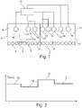
- FIG. 1 shows schematically a roller hearth furnace 1, in which a method for heating a metallic component 2 to a target temperature 3 is carried out.
- the corresponding temperatures are in 2 shown schematically.
- the metallic component 2 is guided into the roller hearth furnace 1 through an access 4 .
- the metallic component 2 is guided over rollers 5 through the roller hearth furnace 1 to the exit 6.
- the metallic component 2 has an Al/Si pre-coating 7 which is formed over the surface and mostly on both sides of the metallic component 2 is.
- access 4 is followed by a heating zone 9, a plateau zone 10, a peak heating zone 11 and an end zone 12.
- the heating zone 9 is at a heating temperature 13
- the plateau zone 10 is at the plateau temperature 14, the peak heating zone 11 tempered (heated) to a peak temperature 15 and the end zone 12 to the target temperature 3 .
- heating means 16 are designed, which are designed here as radiant tubes.
- the individual radiant tubes each include gas burners that burn into a closed (ceramic) tube so that the combustion exhaust gases are not introduced into the furnace in order to prevent hydrogen embrittlement of the metal, which may be promoted by the exhaust gases of the combustion, especially moist exhaust gas.
- each heating means 16 of different strength and/or different heating means 16 such as, for example, partly electric heating means 16 and partly radiant tubes can be configured as heating means 16.
- the rollers 5, which in each zone 9, 10, 11, 12 can be formed in different numbers and/or at different distances and/or from different materials.
- the heating means 16 are connected to a control means 17, by means of which the operation of the heating means 16 can be controlled or regulated and which is suitable and intended for the corresponding activation of the heating means 16.
- at least individual (driven) rollers 5 can also be connected to the control means 17 .
- Shielding means 27 are formed between the zones 9, 10, 11, 12, which in particular reduce or prevent a longitudinal flow between adjacent zones 9, 10, 11, 12.
- the shielding means 27 can be designed in such a way that they prevent thermal radiation between adjacent zones 9, Reduce or eliminate 10, 11, 12.
- the shielding means 27 are formed as internals which reduce the open cross section of the roller hearth furnace 1 and whose height can vary.
- the rollers 5 in the heating zone 9 are made of quartz material, while the rollers in the plateau zone 10, the peak heating zone 11 and the end zone 12 are made of a ceramic material.
- the rollers 5 in the heating zone 9 are preferably made of quartz material in order to be able to absorb the thermal loads on the rollers 5 due to the large temperature difference between the (hot) rollers 5 and the (cold) metallic component 2 .
- the heating means 16 are regulated, for example, in such a way that for a component made of a boron-manganese steel sold as "Usibor 1500" or "MBW 1500+AS", which has an Al/Si pre-coating 7, the heating temperature 13 in the heating zone 9 is a temperature of about 840 to 860°C, in particular 850°C, as plateau temperature 14 in the plateau zone 10 a temperature of about 630°C to 670°C, in particular 650°C with a corridor range of +/-20°C around the melting temperature of the pre-coating 7, a temperature of about 1080 to 1120° C., in particular 1100° C., is set as the peak temperature in the peak heating zone 11 and a temperature of 870 to 940° C. is set as the target temperature 3 in the end zone 12.
- the (cold) metallic component 2 first passes through a heating zone with a heating zone temperature 13, then a plateau zone with a plateau temperature 14 and then an end zone with a target temperature 3. Accordingly, the component temperature 19 follows a curve from a starting temperature to a target temperature 3.
- zone temperature 19 shows an example of a temperature profile with zone temperature 18 and component temperature 19 according to the method proposed here.
- the zone temperature also shows the peak heating zone 11. Comparing the component temperature 19 in this example with the component temperature 19 as in 3 shown, it turns out that the component temperature 19 reaches the target temperature 3 faster with the method proposed here than with the method assumed to be known as in FIG 3 shown.
- a first intermediate zone 20 is formed between the heating zone 9 and the plateau zone 10 , the first intermediate zone temperature 21 of which lies between the heating temperature 13 and the plateau temperature 14 .
- a heat exchange between the heating zone 9 and the plateau zone 10 is reduced or prevented by the first intermediate zone 20, so that a more precise control of the furnace temperature in the zones 9, 10 is possible.
- the zone temperature shows 18 in 4 two second intermediate zones 22 between the plateau zone 10 and the peak heating zone 11, which have two second intermediate zone temperatures 23. These serve to define the peak heating zone 11 and the plateau zone 10 more precisely figure 1 referred.
- FIG. 6 shows a device 24 for the heat treatment of a metallic component 2 with a roller hearth furnace 1 and a press hardening unit 25.
- target temperature 3 in roller hearth furnace 1 it is possible to select target temperature 3 in roller hearth furnace 1 so that it is at or above the AC1 temperature (i.e. the temperature at which the formation of austenite begins during a heating process), or even above the AC3 temperature (the Temperature at which the transformation of Ferrite ends in austenite during a heating process) of the corresponding material of the metallic component 2 to be selected such that at least a proportion of martensite is formed in the metallic component during the subsequent press hardening.
- the AC1 temperature i.e. the temperature at which the formation of austenite begins during a heating process
- AC3 temperature the Temperature at which the transformation of Ferrite ends in austenite during a heating process
- At least one temperature control unit 26 is formed between roller hearth furnace 1 and press hardening unit 25 (see FIG 7 ), which allows, after the (uniform) heating of the metallic component 2 in the roller hearth furnace 1, to have different temperatures in areas of the metallic component 2, in particular to heat partial areas and to cool other partial areas.
- a process can be selected in which the target temperature 3 is selected so that it is below the AC3 or even AC1 temperature and then in a subsequent temperature control unit 26 in at least a partial area of the metallic component 2 the temperature is above the AC1 or AC3 temperature is increased while the temperature is left in at least one other portion of the metallic component 2 below the AC1 or AC3 temperature.
- metallic components 2 can be produced which, after press hardening, have areas of different microstructures or strengths.
Landscapes
- Engineering & Computer Science (AREA)
- Chemical & Material Sciences (AREA)
- Mechanical Engineering (AREA)
- General Engineering & Computer Science (AREA)
- Metallurgy (AREA)
- Thermal Sciences (AREA)
- Crystallography & Structural Chemistry (AREA)
- Materials Engineering (AREA)
- Physics & Mathematics (AREA)
- Organic Chemistry (AREA)
- Combustion & Propulsion (AREA)
- Tunnel Furnaces (AREA)
- Heat Treatments In General, Especially Conveying And Cooling (AREA)
- Heat Treatment Of Strip Materials And Filament Materials (AREA)
- Control Of Heat Treatment Processes (AREA)
- Coating With Molten Metal (AREA)
Claims (12)
- Procédé pour le chauffage d'un composant (2) métallique à une température cible (3), dans lequel le composant (2) présente un pré-revêtement (7) et est guidé à travers un four (1) qui présente au moins quatre zones (9, 10, 11, 12) pouvant être respectivement régulées à une température de zone individuelle (13, 14, 15, 3), le composant (2) étant guidé à travers successivement au moins une zone de chauffage (9), une zone de plateau (10), une zone de chauffage de pointe (11) et une zone d'extrémité (12), la zone de chauffage (9) étant régulée à une température de chauffage (13), la zone de plateau (10) étant régulée à une température de plateau (14), la zone de chauffage de pointe (11) étant régulée à une température de pointe (15) et la zone d'extrémité (12) étant régulée à la température cible (3), la température de plateau (14) étant choisie de sorte que la température du composant (2) dans la zone de plateau (10) se situe dans une plage de corridor de +/-30 K autour d'une température de fusion du pré-revêtement (7), caractérisé en ce que la température de pointe (15) est supérieure à la température cible (3) d'au moins 100 K [Kelvin].
- Procédé selon la revendication 1, dans lequel le pré-revêtement (7) est formé d'un matériau comprenant de l'aluminium et du silicium.
- Procédé selon l'une des revendications précédentes, dans lequel la zone de chauffage de pointe (11) est directement contiguë à la zone de plateau (10).
- Procédé selon l'une des revendications 1 ou 2, dans lequel au moins une zone intermédiaire (22) est formée entre la zone de plateau (10) et la zone de chauffage de pointe (11), laquelle zone intermédiaire est régulée à une température de zone intermédiaire (23) comprise entre la température de la zone précédente (10, 22) et la température de pointe (15).
- Procédé selon l'une des revendications précédentes, dans lequel le composant (2) est guidé dans la zone de chauffage (9) sur des rouleaux (5) fabriqués à partir d'un matériau de quartz.
- Procédé selon l'une des revendications précédentes, dans lequel le composant (2) est guidé dans au moins l'une des zones suivantes :d) la zone de plateau (10) ;e) la zone de chauffage de pointe (11) ; etf) la zone d'extrémité (12)sur des rouleaux (5) fabriqués à partir d'un matériau céramique.
- Four à rouleaux (1) pour le chauffage d'un composant (2) métallique présentant un pré-revêtement (7) à une température cible (3), en particulier selon un procédé selon l'une des revendications précédentes, dans lequel le composant (2) peut être guidé sur des rouleaux (5) depuis une entrée (4) à travers le four à rouleaux (1) vers une sortie (6), comprenant en outre au moins quatre moyens de chauffage (16), à travers lesquels respectivement une température individuelle est réglable dans une zone (9, 10, 11, 12) autour des moyens de chauffage (16), et un moyen de commande (17) pour la commande de manière individuelle d'au moins quatre des moyens de chauffage (16), caractérisé en ce que le moyen de commande (17) est adapté et configuré d'une manière pour commander le moyen de chauffage (16) telle que de l'entrée (4) vers la sortie (6), dans le présent ordre, au moins les zones suivantes (9, 10, 11, 12) peuvent être formées : une zone de chauffage (9) qui peut être régulée à une température de chauffage (13), une zone de plateau (10) qui peut être régulée à une température de plateau (14), une zone de chauffage de pointe (11) qui peut être régulée à une température de pointe (15) et une zone d'extrémité (12) qui peut être régulée à la température cible, le moyen de commande (17) et le moyen de chauffage (16) étant adaptés et configurés pour établir une température de plateau (14) qui se situe dans une plage de corridor de +/- 30 K autour d'une température de fusion du pré-revêtement (7) et pour établir une température de pointe (15) qui se situe au moins 100 K au-dessus de la température cible (3).
- Four à rouleaux (1) selon la revendication 7, dans lequel dans la zone de chauffage (9), les rouleaux (5) sont fabriqués à partir d'un matériau de quartz.
- Four à rouleaux (1) selon l'une des revendications 7 ou 8, dans lequel dans au moins l'une des zones suivantes :a. la zone de plateau (10) ;b. la zone de chauffage de pointe (11) ; etc. la zone d'extrémité (12)les rouleaux (5) sont fabriqués à partir d'un matériau céramique.
- Four à rouleaux (1) selon l'une des revendications 7 à 9, dans lequel des moyens de blindage (27) sont formés entre au moins deux zones adjacentes (9, 10, 11, 12).
- Procédé pour la trempe sous presse d'un composant (2) métallique, dans lequel un composant métallique (3) chauffé à la température cible (3) selon le procédé selon l'une des revendications 1 à 6 est soumis à une trempe sous presse dans un dispositif de trempe sous presse (25).
- Procédé selon la revendication 11, dans lequel le composant métallique est amené, entre le chauffage et la trempe sous presse, à au moins une unité de régulation de température (26) dans laquelle la température d'au moins une zone partielle du composant (3) métallique est modifiée.
Applications Claiming Priority (2)
| Application Number | Priority Date | Filing Date | Title |
|---|---|---|---|
| DE102017120128.9A DE102017120128A1 (de) | 2017-09-01 | 2017-09-01 | Verfahren zum Erwärmen eines metallischen Bauteils auf eine Zieltemperatur und entsprechender Rollenherdofen |
| PCT/EP2018/073474 WO2019043161A1 (fr) | 2017-09-01 | 2018-08-31 | Procédé pour chauffer une pièce métallique à une température finale et four à rouleaux correspondant |
Publications (2)
| Publication Number | Publication Date |
|---|---|
| EP3676408A1 EP3676408A1 (fr) | 2020-07-08 |
| EP3676408B1 true EP3676408B1 (fr) | 2022-07-13 |
Family
ID=63517867
Family Applications (1)
| Application Number | Title | Priority Date | Filing Date |
|---|---|---|---|
| EP18765599.8A Active EP3676408B1 (fr) | 2017-09-01 | 2018-08-31 | Procédé pour chauffer une pièce métallique à une température finale et four à rouleaux correspondant |
Country Status (9)
| Country | Link |
|---|---|
| US (1) | US11584972B2 (fr) |
| EP (1) | EP3676408B1 (fr) |
| CN (1) | CN111108221A (fr) |
| DE (1) | DE102017120128A1 (fr) |
| ES (1) | ES2926293T3 (fr) |
| HU (1) | HUE059961T2 (fr) |
| MX (1) | MX2020002291A (fr) |
| PL (1) | PL3676408T3 (fr) |
| WO (1) | WO2019043161A1 (fr) |
Families Citing this family (11)
| Publication number | Priority date | Publication date | Assignee | Title |
|---|---|---|---|---|
| WO2021125577A1 (fr) * | 2019-12-20 | 2021-06-24 | 현대제철 주식회사 | Composant estampé à chaud et procédé de fabrication associé |
| DE102020106139A1 (de) * | 2020-03-06 | 2021-09-09 | Schwartz Gmbh | Thermisches Behandeln eines Bauteils |
| DE102020212465A1 (de) * | 2020-10-01 | 2022-04-07 | Thyssenkrupp Steel Europe Ag | Verfahren zur Herstellung eines zumindest teilweise pressgehärten Stahlblechbauteils und zumindest teilweise pressgehärtetes Stahlblechbauteil |
| DE102020127057A1 (de) * | 2020-10-14 | 2022-04-14 | Benteler Automobiltechnik Gmbh | Verfahren zur Herstellung einer Stahlplatine sowie Temperierstation |
| KR102399887B1 (ko) * | 2020-12-09 | 2022-05-20 | 현대제철 주식회사 | 핫 스탬핑 부품 및 이의 제조 방법 |
| DE102020133462A1 (de) * | 2020-12-15 | 2022-06-15 | Schwartz Gmbh | Thermisches Behandeln von Bauteilen |
| KR102366284B1 (ko) * | 2020-12-28 | 2022-02-23 | 현대제철 주식회사 | 핫 스탬핑 부품 및 그 제조방법 |
| EP4074845A1 (fr) * | 2021-04-16 | 2022-10-19 | Aerospace Transmission Technologies GmbH | Dispositif de commande et procédé de commande d'une installation de trempe à la presse |
| EP4074846A1 (fr) * | 2021-04-16 | 2022-10-19 | Aerospace Transmission Technologies GmbH | Dispositif de commande et procédé de commande d'une installation de trempe à la presse |
| DE102023105207A1 (de) * | 2023-03-02 | 2024-09-05 | Thyssenkrupp Steel Europe Ag | Verfahren zum Warmpressformen mit verbesserten Eigenschaften |
| CN119220788A (zh) * | 2024-10-10 | 2024-12-31 | 山东一然环保科技有限公司 | 一种辊底式热处理装置和金属板材热处理方法 |
Citations (1)
| Publication number | Priority date | Publication date | Assignee | Title |
|---|---|---|---|---|
| DE102010029082A1 (de) * | 2010-05-18 | 2011-11-24 | Eva Schwartz | Durchlaufofen zum Erwärmen von Werkstücken mit hoher Aufheizrate im Eingangsbereich |
Family Cites Families (23)
| Publication number | Priority date | Publication date | Assignee | Title |
|---|---|---|---|---|
| JPS629039A (ja) | 1985-07-04 | 1987-01-17 | Bridgestone Corp | サスペンシヨンブツシユ |
| JPS629042A (ja) | 1985-07-05 | 1987-01-17 | Toyota Motor Corp | 防振ゴム装置 |
| JPH0629638B2 (ja) | 1986-02-08 | 1994-04-20 | 丸五ゴム工業株式会社 | 流体入りブツシユ |
| US5147083A (en) * | 1991-09-25 | 1992-09-15 | General Motors Corporation | Method and apparatus for convection brazing of aluminum heat exchangers |
| US7413592B2 (en) * | 2004-03-31 | 2008-08-19 | Nu-Iron Technology, Llc | Linear hearth furnace system and methods regarding same |
| CN2885881Y (zh) * | 2006-04-10 | 2007-04-04 | 范本良 | 全电辊底式连续退火炉 |
| DE102007057855B3 (de) * | 2007-11-29 | 2008-10-30 | Benteler Automobiltechnik Gmbh | Verfahren zur Herstellung eines Formbauteils mit mindestens zwei Gefügebereichen unterschiedlicher Duktilität |
| KR101045839B1 (ko) * | 2008-10-02 | 2011-07-01 | 주식회사 엠에스 오토텍 | 핫스탬핑용 가열로 장치 |
| DE102009050879B3 (de) * | 2009-10-27 | 2011-09-01 | Itg Induktionsanlagen Gmbh | Verfahren und Vorrichtung zur Erwärmung von Platinen |
| DE102010017905B4 (de) * | 2010-04-21 | 2014-08-21 | TRUMPF Hüttinger GmbH + Co. KG | Verfahren und Induktionserwärmungsvorrichtung zur Warmblechumformung |
| ES2635765T5 (es) * | 2011-03-10 | 2020-09-28 | Schwartz Gmbh | Sistema de horno y procedimiento para el calentamiento parcial de piezas de chapa de acero |
| RU2014103103A (ru) * | 2011-06-30 | 2015-08-10 | Эбнер Индустриофенбау Гмбх | Способ нагрева фасонной детали для последующей закалки под прессом, а также проходная печь для зонного нагрева подогретой до заданной температуры фасонной детали до более высокой температуры |
| DE202012013282U1 (de) * | 2012-09-04 | 2015-11-20 | Schwartz Gmbh | Tragmittel für Öfen |
| DE102012221120B4 (de) * | 2012-11-19 | 2017-01-26 | Kirchhoff Automotive Deutschland Gmbh | Rollenherdofen und Verfahren zur Wärmebehandlung von metallischen Blechen |
| DE102013107870A1 (de) * | 2013-07-23 | 2015-01-29 | Benteler Automobiltechnik Gmbh | Verfahren zur Herstellung von Formbauteilen sowie Formbauteil und Durchlaufofen |
| DE102013015347A1 (de) * | 2013-09-17 | 2015-03-19 | Schuler Pressen Gmbh | Ofen zur Erwärmung eines Stahlblechs |
| PL2905346T3 (pl) * | 2014-01-23 | 2021-03-08 | Schwartz Gmbh | Sposób obróbki cieplnej |
| DE102014205061A1 (de) | 2014-03-19 | 2015-09-24 | Contitech Luftfedersysteme Gmbh | Hydraulische Buchse |
| WO2016001701A1 (fr) * | 2014-07-03 | 2016-01-07 | Arcelormittal | Ligne de traitement polyvalent pour traitement thermique et plaquage par immersion à chaud d'une bande d'acier |
| DE102014110415B4 (de) * | 2014-07-23 | 2016-10-20 | Voestalpine Stahl Gmbh | Verfahren zum Aufheizen von Stahlblechen und Vorrichtung zur Durchführung des Verfahrens |
| EP3144620A1 (fr) * | 2015-09-18 | 2017-03-22 | Schwartz GmbH | Installation de traitement thermique |
| DE102016100648B4 (de) | 2015-12-23 | 2018-04-12 | Benteler Automobiltechnik Gmbh | Wärmebehandlungsofen sowie Verfahren zur Wärmebehandlung einer vorbeschichteten Stahlblechplatine und Verfahren zur Herstellung eines Kraftfahrzeugbauteils |
| WO2017129600A1 (fr) * | 2016-01-25 | 2017-08-03 | Schwartz Gmbh | Procede de traitement thermique d'un élément métallique |
-
2017
- 2017-09-01 DE DE102017120128.9A patent/DE102017120128A1/de active Pending
-
2018
- 2018-08-31 EP EP18765599.8A patent/EP3676408B1/fr active Active
- 2018-08-31 WO PCT/EP2018/073474 patent/WO2019043161A1/fr not_active Ceased
- 2018-08-31 MX MX2020002291A patent/MX2020002291A/es unknown
- 2018-08-31 HU HUE18765599A patent/HUE059961T2/hu unknown
- 2018-08-31 US US16/642,404 patent/US11584972B2/en active Active
- 2018-08-31 PL PL18765599.8T patent/PL3676408T3/pl unknown
- 2018-08-31 CN CN201880056897.6A patent/CN111108221A/zh active Pending
- 2018-08-31 ES ES18765599T patent/ES2926293T3/es active Active
Patent Citations (1)
| Publication number | Priority date | Publication date | Assignee | Title |
|---|---|---|---|---|
| DE102010029082A1 (de) * | 2010-05-18 | 2011-11-24 | Eva Schwartz | Durchlaufofen zum Erwärmen von Werkstücken mit hoher Aufheizrate im Eingangsbereich |
Also Published As
| Publication number | Publication date |
|---|---|
| PL3676408T3 (pl) | 2022-11-21 |
| US11584972B2 (en) | 2023-02-21 |
| US20210155996A1 (en) | 2021-05-27 |
| MX2020002291A (es) | 2020-07-13 |
| HUE059961T2 (hu) | 2023-01-28 |
| CN111108221A (zh) | 2020-05-05 |
| EP3676408A1 (fr) | 2020-07-08 |
| DE102017120128A1 (de) | 2019-03-07 |
| WO2019043161A1 (fr) | 2019-03-07 |
| ES2926293T3 (es) | 2022-10-25 |
Similar Documents
| Publication | Publication Date | Title |
|---|---|---|
| EP3676408B1 (fr) | Procédé pour chauffer une pièce métallique à une température finale et four à rouleaux correspondant | |
| EP2655672B1 (fr) | Procédé pour produire des éléments de construction durcis pourvus de zones de différentes duretés et/ou ductilités | |
| DE102007057855B3 (de) | Verfahren zur Herstellung eines Formbauteils mit mindestens zwei Gefügebereichen unterschiedlicher Duktilität | |
| EP3652352B1 (fr) | Procédé et dispositif de traitement thermique d'une pièce métallique | |
| DE102010049205B4 (de) | Warmumformlinie und Verfahren zum Warmumformen von blechförmigem Material | |
| DE102013100682B3 (de) | Verfahren zum Erzeugen gehärteter Bauteile und ein Strukturbauteil, welches nach dem Verfahren hergestellt ist | |
| WO2012156084A1 (fr) | Traitement thermique de pièces en tôle pouvant être trempées | |
| DE102016100648B4 (de) | Wärmebehandlungsofen sowie Verfahren zur Wärmebehandlung einer vorbeschichteten Stahlblechplatine und Verfahren zur Herstellung eines Kraftfahrzeugbauteils | |
| EP3013988A1 (fr) | Procédé et équipement de fabrication d'un composant en tôle d'acier trempé sous presse | |
| DE102011056444A1 (de) | Verfahren und Vorrichtung zum partiellen Härten von Blechbauteilen | |
| WO2018234102A1 (fr) | Procédé de fabrication d'un composant en acier pourvu d'un revêtement métallique anticorrosion | |
| EP3408420B1 (fr) | Procédé de traitement thermique d'un composant métallique | |
| EP3365469B1 (fr) | Procédé de fabrication d'un élément structural en acier pour un véhicule | |
| EP3159419B1 (fr) | Procédé de fabrication des profiles laminés partiellement durcis | |
| DE102020106996A1 (de) | Chargenofen für presszuhärtende Platinen oder formzuhärtende Bauteile und Verfahren zur Wärmebehandlung von presszuhärtenden Platinen oder formzuhärtenden Bauteilen | |
| EP2818571B1 (fr) | Incorporation par diffusion de silicium-aluminium dans une bande de tôle d'acier | |
| EP2679692A1 (fr) | Procédé de fabrication d'un composant de formage en tôle d'acier durci par une presse | |
| EP3408421B1 (fr) | Procédé et dispositif pour traitement thermique d'un composant en acier | |
| EP3184655A1 (fr) | Four à traitement thermique et procédé de traitement thermique d'une plaque de tôle d'acier et procédé de production d'un composant de véhicule | |
| DE102016120605A1 (de) | Verfahren und Vorrichtung zur Wärmebehandlung eines metallischen Bauteils | |
| WO2020079200A1 (fr) | Procédé de fabrication d'un produit en acier plat thermofaçonné | |
| DE102021214024A1 (de) | Verfahren zur Herstellung eines warmumgeformten und pressgehärteten Stahlblechbauteil | |
| DE102017216177B4 (de) | Verfahren zur Herstellung eines Zusammenbau-Formteils mittels einer vorkonditionierten Fremdstruktur und Zusammenbau-Formteil | |
| WO2020224983A1 (fr) | Procédé de traitement thermique d'un produit métallique | |
| DE102016219579A1 (de) | Verfahren zur Wärmebehandlung und Einrichtung zur Wärmebehandlung |
Legal Events
| Date | Code | Title | Description |
|---|---|---|---|
| STAA | Information on the status of an ep patent application or granted ep patent |
Free format text: STATUS: UNKNOWN |
|
| STAA | Information on the status of an ep patent application or granted ep patent |
Free format text: STATUS: THE INTERNATIONAL PUBLICATION HAS BEEN MADE |
|
| PUAI | Public reference made under article 153(3) epc to a published international application that has entered the european phase |
Free format text: ORIGINAL CODE: 0009012 |
|
| STAA | Information on the status of an ep patent application or granted ep patent |
Free format text: STATUS: REQUEST FOR EXAMINATION WAS MADE |
|
| 17P | Request for examination filed |
Effective date: 20200225 |
|
| AK | Designated contracting states |
Kind code of ref document: A1 Designated state(s): AL AT BE BG CH CY CZ DE DK EE ES FI FR GB GR HR HU IE IS IT LI LT LU LV MC MK MT NL NO PL PT RO RS SE SI SK SM TR |
|
| AX | Request for extension of the european patent |
Extension state: BA ME |
|
| DAV | Request for validation of the european patent (deleted) | ||
| DAX | Request for extension of the european patent (deleted) | ||
| GRAP | Despatch of communication of intention to grant a patent |
Free format text: ORIGINAL CODE: EPIDOSNIGR1 |
|
| STAA | Information on the status of an ep patent application or granted ep patent |
Free format text: STATUS: GRANT OF PATENT IS INTENDED |
|
| RIC1 | Information provided on ipc code assigned before grant |
Ipc: F27B 9/10 20060101ALI20220207BHEP Ipc: F27B 9/24 20060101ALI20220207BHEP Ipc: C21D 9/00 20060101AFI20220207BHEP |
|
| INTG | Intention to grant announced |
Effective date: 20220304 |
|
| GRAS | Grant fee paid |
Free format text: ORIGINAL CODE: EPIDOSNIGR3 |
|
| GRAA | (expected) grant |
Free format text: ORIGINAL CODE: 0009210 |
|
| STAA | Information on the status of an ep patent application or granted ep patent |
Free format text: STATUS: THE PATENT HAS BEEN GRANTED |
|
| AK | Designated contracting states |
Kind code of ref document: B1 Designated state(s): AL AT BE BG CH CY CZ DE DK EE ES FI FR GB GR HR HU IE IS IT LI LT LU LV MC MK MT NL NO PL PT RO RS SE SI SK SM TR |
|
| REG | Reference to a national code |
Ref country code: CH Ref legal event code: EP |
|
| REG | Reference to a national code |
Ref country code: DE Ref legal event code: R096 Ref document number: 502018010154 Country of ref document: DE |
|
| REG | Reference to a national code |
Ref country code: AT Ref legal event code: REF Ref document number: 1504326 Country of ref document: AT Kind code of ref document: T Effective date: 20220815 |
|
| REG | Reference to a national code |
Ref country code: IE Ref legal event code: FG4D Free format text: LANGUAGE OF EP DOCUMENT: GERMAN |
|
| REG | Reference to a national code |
Ref country code: ES Ref legal event code: FG2A Ref document number: 2926293 Country of ref document: ES Kind code of ref document: T3 Effective date: 20221025 |
|
| REG | Reference to a national code |
Ref country code: LT Ref legal event code: MG9D |
|
| REG | Reference to a national code |
Ref country code: NL Ref legal event code: MP Effective date: 20220713 |
|
| REG | Reference to a national code |
Ref country code: HU Ref legal event code: AG4A Ref document number: E059961 Country of ref document: HU |
|
| PG25 | Lapsed in a contracting state [announced via postgrant information from national office to epo] |
Ref country code: SE Free format text: LAPSE BECAUSE OF FAILURE TO SUBMIT A TRANSLATION OF THE DESCRIPTION OR TO PAY THE FEE WITHIN THE PRESCRIBED TIME-LIMIT Effective date: 20220713 Ref country code: RS Free format text: LAPSE BECAUSE OF FAILURE TO SUBMIT A TRANSLATION OF THE DESCRIPTION OR TO PAY THE FEE WITHIN THE PRESCRIBED TIME-LIMIT Effective date: 20220713 Ref country code: PT Free format text: LAPSE BECAUSE OF FAILURE TO SUBMIT A TRANSLATION OF THE DESCRIPTION OR TO PAY THE FEE WITHIN THE PRESCRIBED TIME-LIMIT Effective date: 20221114 Ref country code: NO Free format text: LAPSE BECAUSE OF FAILURE TO SUBMIT A TRANSLATION OF THE DESCRIPTION OR TO PAY THE FEE WITHIN THE PRESCRIBED TIME-LIMIT Effective date: 20221013 Ref country code: NL Free format text: LAPSE BECAUSE OF FAILURE TO SUBMIT A TRANSLATION OF THE DESCRIPTION OR TO PAY THE FEE WITHIN THE PRESCRIBED TIME-LIMIT Effective date: 20220713 Ref country code: LV Free format text: LAPSE BECAUSE OF FAILURE TO SUBMIT A TRANSLATION OF THE DESCRIPTION OR TO PAY THE FEE WITHIN THE PRESCRIBED TIME-LIMIT Effective date: 20220713 Ref country code: LT Free format text: LAPSE BECAUSE OF FAILURE TO SUBMIT A TRANSLATION OF THE DESCRIPTION OR TO PAY THE FEE WITHIN THE PRESCRIBED TIME-LIMIT Effective date: 20220713 Ref country code: FI Free format text: LAPSE BECAUSE OF FAILURE TO SUBMIT A TRANSLATION OF THE DESCRIPTION OR TO PAY THE FEE WITHIN THE PRESCRIBED TIME-LIMIT Effective date: 20220713 |
|
| PG25 | Lapsed in a contracting state [announced via postgrant information from national office to epo] |
Ref country code: IS Free format text: LAPSE BECAUSE OF FAILURE TO SUBMIT A TRANSLATION OF THE DESCRIPTION OR TO PAY THE FEE WITHIN THE PRESCRIBED TIME-LIMIT Effective date: 20221113 Ref country code: HR Free format text: LAPSE BECAUSE OF FAILURE TO SUBMIT A TRANSLATION OF THE DESCRIPTION OR TO PAY THE FEE WITHIN THE PRESCRIBED TIME-LIMIT Effective date: 20220713 Ref country code: GR Free format text: LAPSE BECAUSE OF FAILURE TO SUBMIT A TRANSLATION OF THE DESCRIPTION OR TO PAY THE FEE WITHIN THE PRESCRIBED TIME-LIMIT Effective date: 20221014 |
|
| REG | Reference to a national code |
Ref country code: CH Ref legal event code: PL |
|
| REG | Reference to a national code |
Ref country code: DE Ref legal event code: R097 Ref document number: 502018010154 Country of ref document: DE |
|
| PG25 | Lapsed in a contracting state [announced via postgrant information from national office to epo] |
Ref country code: SM Free format text: LAPSE BECAUSE OF FAILURE TO SUBMIT A TRANSLATION OF THE DESCRIPTION OR TO PAY THE FEE WITHIN THE PRESCRIBED TIME-LIMIT Effective date: 20220713 Ref country code: RO Free format text: LAPSE BECAUSE OF FAILURE TO SUBMIT A TRANSLATION OF THE DESCRIPTION OR TO PAY THE FEE WITHIN THE PRESCRIBED TIME-LIMIT Effective date: 20220713 Ref country code: MC Free format text: LAPSE BECAUSE OF FAILURE TO SUBMIT A TRANSLATION OF THE DESCRIPTION OR TO PAY THE FEE WITHIN THE PRESCRIBED TIME-LIMIT Effective date: 20220713 Ref country code: LU Free format text: LAPSE BECAUSE OF NON-PAYMENT OF DUE FEES Effective date: 20220831 Ref country code: LI Free format text: LAPSE BECAUSE OF NON-PAYMENT OF DUE FEES Effective date: 20220831 Ref country code: DK Free format text: LAPSE BECAUSE OF FAILURE TO SUBMIT A TRANSLATION OF THE DESCRIPTION OR TO PAY THE FEE WITHIN THE PRESCRIBED TIME-LIMIT Effective date: 20220713 Ref country code: CH Free format text: LAPSE BECAUSE OF NON-PAYMENT OF DUE FEES Effective date: 20220831 |
|
| REG | Reference to a national code |
Ref country code: BE Ref legal event code: MM Effective date: 20220831 |
|
| PLBE | No opposition filed within time limit |
Free format text: ORIGINAL CODE: 0009261 |
|
| STAA | Information on the status of an ep patent application or granted ep patent |
Free format text: STATUS: NO OPPOSITION FILED WITHIN TIME LIMIT |
|
| PG25 | Lapsed in a contracting state [announced via postgrant information from national office to epo] |
Ref country code: SK Free format text: LAPSE BECAUSE OF FAILURE TO SUBMIT A TRANSLATION OF THE DESCRIPTION OR TO PAY THE FEE WITHIN THE PRESCRIBED TIME-LIMIT Effective date: 20220713 Ref country code: EE Free format text: LAPSE BECAUSE OF FAILURE TO SUBMIT A TRANSLATION OF THE DESCRIPTION OR TO PAY THE FEE WITHIN THE PRESCRIBED TIME-LIMIT Effective date: 20220713 |
|
| 26N | No opposition filed |
Effective date: 20230414 |
|
| P01 | Opt-out of the competence of the unified patent court (upc) registered |
Effective date: 20230516 |
|
| GBPC | Gb: european patent ceased through non-payment of renewal fee |
Effective date: 20221013 |
|
| PG25 | Lapsed in a contracting state [announced via postgrant information from national office to epo] |
Ref country code: AL Free format text: LAPSE BECAUSE OF FAILURE TO SUBMIT A TRANSLATION OF THE DESCRIPTION OR TO PAY THE FEE WITHIN THE PRESCRIBED TIME-LIMIT Effective date: 20220713 |
|
| PG25 | Lapsed in a contracting state [announced via postgrant information from national office to epo] |
Ref country code: IE Free format text: LAPSE BECAUSE OF NON-PAYMENT OF DUE FEES Effective date: 20220831 Ref country code: FR Free format text: LAPSE BECAUSE OF NON-PAYMENT OF DUE FEES Effective date: 20220913 |
|
| PG25 | Lapsed in a contracting state [announced via postgrant information from national office to epo] |
Ref country code: SI Free format text: LAPSE BECAUSE OF FAILURE TO SUBMIT A TRANSLATION OF THE DESCRIPTION OR TO PAY THE FEE WITHIN THE PRESCRIBED TIME-LIMIT Effective date: 20220713 |
|
| PG25 | Lapsed in a contracting state [announced via postgrant information from national office to epo] |
Ref country code: BE Free format text: LAPSE BECAUSE OF NON-PAYMENT OF DUE FEES Effective date: 20220831 |
|
| PG25 | Lapsed in a contracting state [announced via postgrant information from national office to epo] |
Ref country code: GB Free format text: LAPSE BECAUSE OF NON-PAYMENT OF DUE FEES Effective date: 20221013 |
|
| PG25 | Lapsed in a contracting state [announced via postgrant information from national office to epo] |
Ref country code: IT Free format text: LAPSE BECAUSE OF FAILURE TO SUBMIT A TRANSLATION OF THE DESCRIPTION OR TO PAY THE FEE WITHIN THE PRESCRIBED TIME-LIMIT Effective date: 20220713 |
|
| PG25 | Lapsed in a contracting state [announced via postgrant information from national office to epo] |
Ref country code: CY Free format text: LAPSE BECAUSE OF FAILURE TO SUBMIT A TRANSLATION OF THE DESCRIPTION OR TO PAY THE FEE WITHIN THE PRESCRIBED TIME-LIMIT Effective date: 20220713 |
|
| PG25 | Lapsed in a contracting state [announced via postgrant information from national office to epo] |
Ref country code: MK Free format text: LAPSE BECAUSE OF FAILURE TO SUBMIT A TRANSLATION OF THE DESCRIPTION OR TO PAY THE FEE WITHIN THE PRESCRIBED TIME-LIMIT Effective date: 20220713 |
|
| PG25 | Lapsed in a contracting state [announced via postgrant information from national office to epo] |
Ref country code: TR Free format text: LAPSE BECAUSE OF FAILURE TO SUBMIT A TRANSLATION OF THE DESCRIPTION OR TO PAY THE FEE WITHIN THE PRESCRIBED TIME-LIMIT Effective date: 20220713 |
|
| PG25 | Lapsed in a contracting state [announced via postgrant information from national office to epo] |
Ref country code: BG Free format text: LAPSE BECAUSE OF FAILURE TO SUBMIT A TRANSLATION OF THE DESCRIPTION OR TO PAY THE FEE WITHIN THE PRESCRIBED TIME-LIMIT Effective date: 20220713 |
|
| PG25 | Lapsed in a contracting state [announced via postgrant information from national office to epo] |
Ref country code: MT Free format text: LAPSE BECAUSE OF FAILURE TO SUBMIT A TRANSLATION OF THE DESCRIPTION OR TO PAY THE FEE WITHIN THE PRESCRIBED TIME-LIMIT Effective date: 20220713 |
|
| PGFP | Annual fee paid to national office [announced via postgrant information from national office to epo] |
Ref country code: HU Payment date: 20250825 Year of fee payment: 8 |
|
| PGFP | Annual fee paid to national office [announced via postgrant information from national office to epo] |
Ref country code: ES Payment date: 20250926 Year of fee payment: 8 |
|
| PGFP | Annual fee paid to national office [announced via postgrant information from national office to epo] |
Ref country code: DE Payment date: 20250820 Year of fee payment: 8 |
|
| PGFP | Annual fee paid to national office [announced via postgrant information from national office to epo] |
Ref country code: PL Payment date: 20250724 Year of fee payment: 8 |
|
| PGFP | Annual fee paid to national office [announced via postgrant information from national office to epo] |
Ref country code: AT Payment date: 20250821 Year of fee payment: 8 |
|
| PGFP | Annual fee paid to national office [announced via postgrant information from national office to epo] |
Ref country code: CZ Payment date: 20250827 Year of fee payment: 8 |