EP3676511B1 - Transmission en ligne à deux arbres de renvoi - Google Patents
Transmission en ligne à deux arbres de renvoi Download PDFInfo
- Publication number
- EP3676511B1 EP3676511B1 EP18781961.0A EP18781961A EP3676511B1 EP 3676511 B1 EP3676511 B1 EP 3676511B1 EP 18781961 A EP18781961 A EP 18781961A EP 3676511 B1 EP3676511 B1 EP 3676511B1
- Authority
- EP
- European Patent Office
- Prior art keywords
- gear
- shaft
- gearwheel
- intermediate shaft
- drive
- Prior art date
- Legal status (The legal status is an assumption and is not a legal conclusion. Google has not performed a legal analysis and makes no representation as to the accuracy of the status listed.)
- Active
Links
Images

Classifications
-
- F—MECHANICAL ENGINEERING; LIGHTING; HEATING; WEAPONS; BLASTING
- F16—ENGINEERING ELEMENTS AND UNITS; GENERAL MEASURES FOR PRODUCING AND MAINTAINING EFFECTIVE FUNCTIONING OF MACHINES OR INSTALLATIONS; THERMAL INSULATION IN GENERAL
- F16H—GEARING
- F16H57/00—General details of gearing
- F16H57/02—Gearboxes; Mounting gearing therein
- F16H57/021—Shaft support structures, e.g. partition walls, bearing eyes, casing walls or covers with bearings
-
- F—MECHANICAL ENGINEERING; LIGHTING; HEATING; WEAPONS; BLASTING
- F16—ENGINEERING ELEMENTS AND UNITS; GENERAL MEASURES FOR PRODUCING AND MAINTAINING EFFECTIVE FUNCTIONING OF MACHINES OR INSTALLATIONS; THERMAL INSULATION IN GENERAL
- F16H—GEARING
- F16H3/00—Toothed gearings for conveying rotary motion with variable gear ratio or for reversing rotary motion
- F16H3/02—Toothed gearings for conveying rotary motion with variable gear ratio or for reversing rotary motion without gears having orbital motion
- F16H3/08—Toothed gearings for conveying rotary motion with variable gear ratio or for reversing rotary motion without gears having orbital motion exclusively or essentially with continuously meshing gears, that can be disengaged from their shafts
- F16H3/087—Toothed gearings for conveying rotary motion with variable gear ratio or for reversing rotary motion without gears having orbital motion exclusively or essentially with continuously meshing gears, that can be disengaged from their shafts characterised by the disposition of the gears
- F16H3/093—Toothed gearings for conveying rotary motion with variable gear ratio or for reversing rotary motion without gears having orbital motion exclusively or essentially with continuously meshing gears, that can be disengaged from their shafts characterised by the disposition of the gears with two or more countershafts
-
- F—MECHANICAL ENGINEERING; LIGHTING; HEATING; WEAPONS; BLASTING
- F16—ENGINEERING ELEMENTS AND UNITS; GENERAL MEASURES FOR PRODUCING AND MAINTAINING EFFECTIVE FUNCTIONING OF MACHINES OR INSTALLATIONS; THERMAL INSULATION IN GENERAL
- F16H—GEARING
- F16H3/00—Toothed gearings for conveying rotary motion with variable gear ratio or for reversing rotary motion
- F16H3/02—Toothed gearings for conveying rotary motion with variable gear ratio or for reversing rotary motion without gears having orbital motion
- F16H3/08—Toothed gearings for conveying rotary motion with variable gear ratio or for reversing rotary motion without gears having orbital motion exclusively or essentially with continuously meshing gears, that can be disengaged from their shafts
- F16H3/087—Toothed gearings for conveying rotary motion with variable gear ratio or for reversing rotary motion without gears having orbital motion exclusively or essentially with continuously meshing gears, that can be disengaged from their shafts characterised by the disposition of the gears
- F16H3/093—Toothed gearings for conveying rotary motion with variable gear ratio or for reversing rotary motion without gears having orbital motion exclusively or essentially with continuously meshing gears, that can be disengaged from their shafts characterised by the disposition of the gears with two or more countershafts
- F16H3/097—Toothed gearings for conveying rotary motion with variable gear ratio or for reversing rotary motion without gears having orbital motion exclusively or essentially with continuously meshing gears, that can be disengaged from their shafts characterised by the disposition of the gears with two or more countershafts the input and output shafts being aligned on the same axis
-
- F—MECHANICAL ENGINEERING; LIGHTING; HEATING; WEAPONS; BLASTING
- F16—ENGINEERING ELEMENTS AND UNITS; GENERAL MEASURES FOR PRODUCING AND MAINTAINING EFFECTIVE FUNCTIONING OF MACHINES OR INSTALLATIONS; THERMAL INSULATION IN GENERAL
- F16H—GEARING
- F16H3/00—Toothed gearings for conveying rotary motion with variable gear ratio or for reversing rotary motion
- F16H3/02—Toothed gearings for conveying rotary motion with variable gear ratio or for reversing rotary motion without gears having orbital motion
- F16H3/08—Toothed gearings for conveying rotary motion with variable gear ratio or for reversing rotary motion without gears having orbital motion exclusively or essentially with continuously meshing gears, that can be disengaged from their shafts
- F16H3/087—Toothed gearings for conveying rotary motion with variable gear ratio or for reversing rotary motion without gears having orbital motion exclusively or essentially with continuously meshing gears, that can be disengaged from their shafts characterised by the disposition of the gears
- F16H3/093—Toothed gearings for conveying rotary motion with variable gear ratio or for reversing rotary motion without gears having orbital motion exclusively or essentially with continuously meshing gears, that can be disengaged from their shafts characterised by the disposition of the gears with two or more countershafts
- F16H2003/0933—Toothed gearings for conveying rotary motion with variable gear ratio or for reversing rotary motion without gears having orbital motion exclusively or essentially with continuously meshing gears, that can be disengaged from their shafts characterised by the disposition of the gears with two or more countershafts with coaxial countershafts
-
- F—MECHANICAL ENGINEERING; LIGHTING; HEATING; WEAPONS; BLASTING
- F16—ENGINEERING ELEMENTS AND UNITS; GENERAL MEASURES FOR PRODUCING AND MAINTAINING EFFECTIVE FUNCTIONING OF MACHINES OR INSTALLATIONS; THERMAL INSULATION IN GENERAL
- F16H—GEARING
- F16H2200/00—Transmissions for multiple ratios
- F16H2200/0013—Transmissions for multiple ratios specially adapted for rear-wheel-driven vehicles
-
- F—MECHANICAL ENGINEERING; LIGHTING; HEATING; WEAPONS; BLASTING
- F16—ENGINEERING ELEMENTS AND UNITS; GENERAL MEASURES FOR PRODUCING AND MAINTAINING EFFECTIVE FUNCTIONING OF MACHINES OR INSTALLATIONS; THERMAL INSULATION IN GENERAL
- F16H—GEARING
- F16H2200/00—Transmissions for multiple ratios
- F16H2200/0026—Transmissions for multiple ratios comprising at least one creep low gear, e.g. additional gear for extra low speed or creeping
-
- F—MECHANICAL ENGINEERING; LIGHTING; HEATING; WEAPONS; BLASTING
- F16—ENGINEERING ELEMENTS AND UNITS; GENERAL MEASURES FOR PRODUCING AND MAINTAINING EFFECTIVE FUNCTIONING OF MACHINES OR INSTALLATIONS; THERMAL INSULATION IN GENERAL
- F16H—GEARING
- F16H2200/00—Transmissions for multiple ratios
- F16H2200/003—Transmissions for multiple ratios characterised by the number of forward speeds
- F16H2200/0047—Transmissions for multiple ratios characterised by the number of forward speeds the gear ratios comprising five forward speeds
-
- F—MECHANICAL ENGINEERING; LIGHTING; HEATING; WEAPONS; BLASTING
- F16—ENGINEERING ELEMENTS AND UNITS; GENERAL MEASURES FOR PRODUCING AND MAINTAINING EFFECTIVE FUNCTIONING OF MACHINES OR INSTALLATIONS; THERMAL INSULATION IN GENERAL
- F16H—GEARING
- F16H2200/00—Transmissions for multiple ratios
- F16H2200/003—Transmissions for multiple ratios characterised by the number of forward speeds
- F16H2200/0052—Transmissions for multiple ratios characterised by the number of forward speeds the gear ratios comprising six forward speeds
-
- F—MECHANICAL ENGINEERING; LIGHTING; HEATING; WEAPONS; BLASTING
- F16—ENGINEERING ELEMENTS AND UNITS; GENERAL MEASURES FOR PRODUCING AND MAINTAINING EFFECTIVE FUNCTIONING OF MACHINES OR INSTALLATIONS; THERMAL INSULATION IN GENERAL
- F16H—GEARING
- F16H2200/00—Transmissions for multiple ratios
- F16H2200/003—Transmissions for multiple ratios characterised by the number of forward speeds
- F16H2200/0056—Transmissions for multiple ratios characterised by the number of forward speeds the gear ratios comprising seven forward speeds
-
- F—MECHANICAL ENGINEERING; LIGHTING; HEATING; WEAPONS; BLASTING
- F16—ENGINEERING ELEMENTS AND UNITS; GENERAL MEASURES FOR PRODUCING AND MAINTAINING EFFECTIVE FUNCTIONING OF MACHINES OR INSTALLATIONS; THERMAL INSULATION IN GENERAL
- F16H—GEARING
- F16H2200/00—Transmissions for multiple ratios
- F16H2200/20—Transmissions using gears with orbital motion
- F16H2200/203—Transmissions using gears with orbital motion characterised by the engaging friction means not of the freewheel type, e.g. friction clutches or brakes
- F16H2200/2038—Transmissions using gears with orbital motion characterised by the engaging friction means not of the freewheel type, e.g. friction clutches or brakes with three engaging means
Definitions
- the invention relates to a gearbox with several shiftable gears for a motor vehicle, the gearbox comprising an input shaft, an output shaft arranged coaxially to the input shaft and a first intermediate shaft and a second intermediate shaft, which are arranged parallel to and spaced from the input shaft.
- Such a transmission which is also referred to as an inline transmission, is, for example, from DE 10 2011 052 440 A1 famous.
- the inline transmission disclosed there comprises a drive-side gear pair which has a drive gear and a first intermediate gear.
- the drive gear is arranged in a rotationally fixed manner on the input shaft and meshes with the first intermediate gear, which is arranged in a rotationally fixed manner on the first intermediate shaft.
- a drive torque which is generated by a motor and fed into the input shaft via a coupling, is passed on to the first intermediate shaft via the gear pair on the drive side.
- the drive torque can be switched from the first intermediate shaft to the output shaft via several gear wheel pairs.
- the gear wheel pairings each have a fixed wheel and a shiftable idler wheel, each idler wheel being able to be connected to one of the transmission shafts in a rotationally fixed manner via a gear shift clutch.
- a gear shift clutch can thus be assigned to each gear of the manual transmission. If the gearshift clutch is closed or if it is in a shift position, the relevant gear is engaged.
- the overall ratio of each gear is also determined.
- This constant ratio is referred to below as the drive constant.
- the drive constant at a value significantly greater than 1 has a positive effect on the toothing forces in the gearbox and the efficiency of the gearbox because the intermediate shaft rotates slowly.
- a large drive constant is generally helpful for realizing the lower gears with large overall ratios.
- the invention is therefore based on the object of providing a manual transmission for a motor vehicle that is simple and compact and has a large range of different gear ratios.
- the gearbox has both a drive-side gear pair and an output-side gear pair.
- the gear pair on the drive side has the drive gear on the input shaft and the first gear on the first intermediate shaft
- the gear pair on the output side has a second intermediate gear on the second intermediate shaft and the drive gear on the output shaft.
- traction mode of the transmission i.e. when drive torque is introduced from the engine via the input shaft into the gearbox to drive the motor vehicle, the drive torque is transmitted from the input shaft to the output shaft via the drive-side gear pair while the gearbox is engaged, while via the output-side Gear pairing no drive torque is transmitted.
- the manual transmission according to the invention thus has at least three gears, the overall ratio of which (ratio of the speed of the input shaft to the speed of the output shaft when a gear is engaged) is independent of the drive constant.
- there is at least one gear in the manual transmission the overall ratio of which is independent of the output constant. Due to this independence of the one switchable gear and the other three switchable gears, a simply constructed
- the drive torque is transmitted via the drive-side gear pair.
- the crawler gear represents the forward gear in the manual transmission, through which the greatest gear ratio can be achieved between the input shaft and the output shaft.
- the gear pair on the output side is preferably switched to be load-free.
- drive torque can be transmitted via the gear pair on the drive side.
- the gear wheel pairing on the output side can also be switched load-free here.
- the drive torque can be transmitted via the gear pair on the output side, while according to the invention the gear pair on the drive side does not transmit any drive torque.
- a gearbox is disclosed in which, depending on the gear engaged, the drive torque is passed either via the drive-side gear pair or the output-side gear pair without the respective other gear pair transferring drive torque.
- the first intermediate shaft can be connected to the second intermediate shaft in a rotationally fixed manner.
- the drive torque can be conducted both via the gear pair on the drive side and via the gear pair on the output side.
- the simultaneous use of the drive-side gear pair and the output-side gear pair for the transmission of drive torque only takes place in a single gear of the gearbox.
- This makes it possible to implement a gearbox with a particularly simple design.
- the total gear ratio corresponds to the product of the drive constant and the output constant.
- this further gear can also be a further reverse gear.
- An x means that the ratio of a gear (forward gear / reverse gear) depends on the corresponding constant.
- the ratio of the fourth forward gear depends neither on the drive constant nor on the output constant.
- Two further forward gears are preferably provided (fifth and sixth forward gears).
- the drive constant preferably assumes values between 2 and 4.
- the drive constant can be two to three times the output constant. Table: Dependency on the input / output constant for an exemplary embodiment: Drive constant Output constant Reverse gear x - Creeper x - First forward gear x x Second forward gear - x Third forward gear - x Fourth forward gear - - More forward gears - x
- the gearbox has no further input shaft. It is therefore not a double clutch transmission that has two input shafts. In this design, the gearbox would only have a single input shaft. Also, it is preferably not a gear which branches the drive torque and in which (partially) drive torque is transmitted simultaneously in the axial direction of the first intermediate shaft and in the axial direction of the second intermediate shaft.
- the first intermediate shaft and the second intermediate shaft are arranged coaxially.
- the first intermediate shaft is designed as an inner shaft and the second intermediate shaft is designed as a hollow shaft.
- the first intermediate gear can be arranged at one end of the first intermediate shaft. This end is preferably a drive-side end of the first intermediate shaft which faces the drive or the engine of the motor vehicle.
- a loose wheel or fixed wheel for the creep speed can be arranged at another end of the first intermediate shaft.
- a fixed gear or an idler gear for the reverse gear can be arranged at the other end of the first intermediate shaft.
- the arrangement of a gear such as a fixed gear or idler gear at one of the two ends of the first intermediate shaft means that there is no further gear of the gearbox at this end that serves to transmit drive torque and is less axially spaced from the relevant end of the intermediate shaft .
- a first double-speed clutch can be arranged on the second intermediate shaft, by means of which the first intermediate gear can be connected in a first shift position / shift position and in a second shift position an idler gear arranged on the second intermediate shaft can be connected non-rotatably to the second intermediate shaft.
- the first forward gear of the gearbox should preferably be engaged in the first shift position of the first double-speed clutch.
- the idler gear arranged on the second intermediate shaft, which can be connected non-rotatably to the second intermediate shaft with said double-speed clutch, can be assigned to the second forward gear of the gearbox.
- an intermediate plate which serves to support the input shaft and / or output shaft and the first intermediate shaft and / or the second intermediate shaft.
- the intermediate plate can be arranged between the gear wheel pairing on the output side and the fixed gear or the idler gear of the reverse gear.
- the intermediate plate can accommodate a first intermediate bearing on which the input shaft and the output shaft are supported. The support can take place in such a way that an axial hollow section of the output shaft is arranged in the radial direction between the intermediate bearing and the input shaft.
- the input shaft is then supported on the first intermediate bearing via the axial hollow section of the output shaft, which can radially encompass one end of the input shaft.
- the intermediate plate can accommodate a second intermediate bearing in order to support the first intermediate shaft and / or the second intermediate shaft.
- the second intermediate bearing preferably serves to support the first intermediate shaft, which is designed as an inner shaft.
- a second double-speed clutch can be arranged between the first double-speed clutch and the output-side gear pair in order to connect idler gears of further forward gears arranged on the input shaft or the second intermediate shaft in a rotationally fixed manner to the input shaft or the second intermediate shaft.
- These further forward gears are preferably a third forward gear and a fourth forward gear. If the idler gears of the third forward gear and the fourth forward gear are on the input shaft, the second double-speed clutch is also arranged on the input shaft.
- the second double-speed clutch is used to connect a gear wheel of a direct gear (direct forward gear) to the input shaft in a rotationally fixed manner, with the input shaft and the output shaft rotating at the same speed when the direct gear is engaged.
- the gear of the direct gear can be designed as a fixed gear on the output shaft, with this fixed wheel has the properties of a loose wheel seated on the input shaft in relation to the input shaft.
- the gearbox can have at least one shiftable gear, the ratio of which is independent of both the drive constant and the output constant. In a preferred exemplary embodiment, however, it is only a single shiftable gear that has said independence.
- the idler gear of the fourth forward gear can also be the output gear, which is part of the gear pair on the output side and is connected to the output shaft in a rotationally fixed manner.
- the second double-speed clutch connects the input shaft in a torque-proof manner with the output gear, which is non-rotatably seated on the output shaft.
- the output gear thus has a double function.
- a further gearshift clutch can be provided between the first double-speed clutch and the second double-speed clutch, preferably in the form of a third double-speed clutch, in order to connect idler gears of further forward gears arranged on the input shaft or the second intermediate shaft in a rotationally fixed manner to the input shaft or the second intermediate shaft.
- the second double-speed clutch and the third double-speed clutch are preferably both arranged on the input shaft. But it is also conceivable that they both sit on the second intermediate shaft or, alternatively, are distributed on different shafts.
- the other forward gears that can be engaged with the help of the third double-speed clutch can be a fifth and sixth forward gear.
- the fourth forward gear is designed as a direct gear
- forward gears with a gear ratio other than 1 can be implemented with the second double-speed clutch and the third double-speed clutch, namely two forward gears, which have a gear ratio less than 1 (fifth and sixth forward gear) and one forward gear (third forward gear), which has a gear ratio greater than 1.
- ratio equal to 1 enables a particularly good gradation of the gears to be achieved, whereby it must be taken into account that the double function of the output gear described above results in a dependency between the ratios of the forward gears given is.
- the idler gears of the following forward gears can be lined up in the following order: second forward gear, fifth forward gear, sixth forward gear, third forward gear, fourth forward gear.
- a gear shift clutch is provided to connect the idler gear of the reverse gear to the shaft on which the idler gear is arranged, the idler gear being arranged in the axial direction between the output-side gear pair and the gear shift clutch.
- the gearshift clutch is preferably designed as a double-gearshift clutch, which can therefore also be referred to as a fourth double-gearshift clutch.
- This fourth double-speed clutch can be used to engage the crawler gear. It is preferred here that the idler gear of the reverse gear is arranged axially closer to the gear wheel pairing on the output side than the idler gear of the crawler gear. This has the advantage that the manual transmission with the crawler gear and the six forward gears (which corresponds to a 7-speed gearbox) can easily be converted into a 6-speed gearbox by omitting the crawler gear and replacing the fourth double-speed clutch with a single-acting gearshift clutch can be modified.
- a single-acting gear shift clutch can be used, with which only one forward gear can be engaged.
- This single-acting gearshift clutch can be located in the axial direction between the first double-gearshift clutch and the second gearshift clutch.
- a 5-speed gearbox can also be implemented, with the different variants basically having the same gearbox architecture.
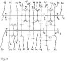
- Figure 1 shows schematically a gearbox according to the invention for a motor vehicle.
- the gearbox has an input shaft 10 and an output shaft 30 which is arranged coaxially to the input shaft 10.
- the two input shafts 10, 30 are mounted rotatably about an axis of rotation 2.
- the gearbox has a first intermediate shaft or countershaft 50 and a second intermediate shaft 70, the first intermediate shaft 50 being arranged as an inner shaft and the second intermediate shaft 70 being arranged as a hollow shaft arranged coaxially therewith.
- the center distance between the axis 2 and an axis 3, about which the intermediate shafts 50, 70 are rotatably mounted, can for example be 80 to 100 mm.
- the gearbox can preferably be installed along the direction of travel of the motor vehicle. In this case, the direction of travel and the axes 2, 3 are parallel to each other.
- a drive gear 11 is arranged on the input shaft 10 in a rotationally fixed manner.
- the drive gear 11 is in meshing engagement with a first intermediate gear 51, which is seated in a rotationally fixed manner on the first intermediate shaft 50.
- the gears 11, 51 form a gear pair on the drive side, by means of which a constant gear ratio (drive constant) is specified between the input shaft 10 and the first intermediate shaft 50.
- the diameter of the first intermediate wheel 51 is approximately 3 to 3.5 times as large as the diameter of the drive gear 11. This results in a corresponding value of 3 to 3.5 for the drive constant.
- the drive gear 11 is in meshing engagement only with the first intermediate gear 11. There are no further gears in the plane of the gears 11, 51. Due to the meshing engagement, the first intermediate gear is connected to the input shaft in a rotationally fixed manner. A non-rotatable connection with two components therefore does not require that the components rotate around the same axis at the same speed.
- the first intermediate gear 51 is arranged at a drive-side end of the first intermediate shaft 50.
- a fixed gear 52 is arranged, which meshes with a loose gear 31 seated on the output shaft 30.
- the idler gear 31 can be connected to the output shaft 30 in a rotationally fixed manner via a double-speed shift clutch 32, which is arranged coaxially to the output shaft 30 and is also referred to here as a fourth double-speed shift clutch.
- a sliding sleeve, designated 33, of the fourth double-speed clutch 32 must be one in the illustration of Figure 1 take right switching position. In this shift position there is a creeper gear Cr of the gearbox in the engaged state.
- a drive torque fed into the input shaft 2 runs in a traction mode of the motor vehicle with the creep gear Cr engaged via the drive gear 11 and the first intermediate gear 51 meshing with it on the first intermediate shaft 50, through which the torque reaches the output shaft 30 via the gears 52, 31.
- a ratio of the creep speed Cr is composed of the drive constant of the drive-side gear pair and the ratio that results from the engagement of the fixed gear 52 on the first intermediate shaft 50 and the idler gear 31 on the output shaft 30. Since the diameter of the idler gear 31 is approximately 1.5 to 2 times as large as that Diameter of the fixed gear 52 results in a (total) gear ratio of 4.5 to 7 for the crawler gear.
- the first intermediate gear 51 can be connected to the second intermediate shaft 70 in a rotationally fixed manner by means of a double-speed clutch 71 (also called the first double-speed clutch) on the second intermediate shaft 70.
- the structure of the first double-speed clutch 71 essentially corresponds to the structure of the fourth double-speed clutch 32 with the sliding sleeve 33.
- a first / second or right / left switching position of one of the double-speed switching clutches is assumed, although the switching position actually relates to the sliding sleeve in question.
- a first forward gear I of the manual transmission is engaged.
- the drive torque is transferred from the intermediate shaft 70 to the output shaft 30 via a second intermediate gear 72 configured as a fixed gear on the second intermediate shaft 70 and a meshing output gear 34 configured as a fixed gear on the output shaft 30 gear pairing on the output side are designated which, like the gear wheel pairing on the drive side with the fixed gears 11, 51, has a constant transmission ratio (constant on the output side).
- the constant on the output side is 1.2 to 1.4 here.
- the (overall) gear ratio of the first forward gear I thus corresponds to the product of the drive constant and the output constant. This results in a ratio of the second forward gear II of 3.6 to 4.9.
- a reversing gear 90 is provided which meshes with a fixed gear 53 on the first intermediate shaft 50.
- the reversing gear 90 in turn meshes with a loose gear 35 on the output shaft 30.
- Similar to the creep gear Cr when the reverse gear R is engaged, the torque flow runs from the input shaft 10 via the first intermediate shaft 50 onto the output shaft 30.
- the second intermediate shaft 70 is switched to be load-free. This means that when the crawler gear Cr is engaged and when the reverse gear R is engaged, no drive torque is passed through the second intermediate shaft 70, although it rotates with the gear pair on the output side.
- the second intermediate shaft 70 In the axial direction, the second intermediate shaft 70 is enclosed by the first intermediate gear 51 and the fixed gear 53 of the reverse gear R. The second intermediate shaft 70 is therefore shorter than the first intermediate shaft 50
- a fourth forward gear IV is engaged when the input shaft 10 is non-rotatably connected to the output gear 34 or to the output shaft 30 by means of a double-speed clutch 12 (second double-speed clutch) seated on the input shaft 10.
- the gear ratio when the fourth forward gear IV is engaged is 1.
- the second double-speed clutch 12 is then in a right or first shift position.
- the fourth forward gear IV can also be referred to as a direct gear.
- a fixed gear 13 and three idler gears 14, 15, 16 are arranged on the input shaft 10.
- the idler gears 14, 15 can be connected non-rotatably to the input shaft 10 by means of a double gear shift clutch 17 (third gear shift clutch) arranged between them.
- the second double-speed clutch 12 is used in addition to the rotationally fixed connection of the output gear 34 to the input shaft 10 also for the rotationally fixed connection of the idler gear 16 to the input shaft 10.
- the second double-speed clutch 12 is moved to a left shift position.
- the fixed gear 13 meshes with an idler gear 73 on the second intermediate shaft 70. If the third double-speed clutch 71 is in a right shift position, the idler gear 73 is non-rotatably connected to the intermediate shaft. This enables a second forward gear II to be implemented.
- the drive torque thus runs via the input shaft and the gears 13, 73 to the second intermediate shaft. Eventually that happens Drive torque via the gear wheel pairing on the output side with the gear wheels 72, 34 on the output shaft 30.
- a third forward gear III, a fifth forward gear V and a sixth forward gear VI can be implemented by means of corresponding shift positions of the double-speed clutches 17, 12.
- the (overall) ratio of the sixth forward gear VI depends on the output constant and is in a range between 0.6 and 0.7.
- the gearbox has no further shafts.
- the gearbox comprises only the shafts 10, 30, which are coaxial to one another, and the intermediate shafts 50, 70, the latter also being arranged coaxially to one another.
- the inline transmission can also be referred to as a 7-speed transmission, in which case the crawler gear is the first forward gear.
- the crawler gear is the first forward gear.
- a first intermediate bearing 5 is indicated, by means of which the input shaft 10 and the output shaft 30 are additionally supported between two main bearings 6 of the shafts 10, 30.
- the first intermediate bearing 5 is in turn supported on an intermediate plate (not shown) in the gearbox, which is located in axial proximity to the gear wheel pairing with the gear wheels 72, 34 on the output side and extends essentially perpendicular to the axis 2.
- a second intermediate storage 7, which is located in the axial Direction between further main bearings 8 for mounting the intermediate shafts 50, 70 is located.
- the second intermediate storage 7 is also supported on the intermediate plate or is incorporated into it.
- the intermediate plate also serves to provide a bearing or a receptacle for the bearing of the reversing wheel 90.
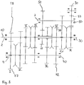
- FIG Figure 2 shows a wheel set which is not according to the invention. Identical or similar components to the components of the embodiment of FIG Figure 1 are provided with the same reference numbers.
- the input shaft 10 also carries a drive gear 11 here, which meshes with the first intermediate gear 51 of the first intermediate shaft 50 and defines the drive constant.
- the drive torque runs from the input shaft 10 via the non-shiftable gears to the first intermediate shaft 50. From there, when the gear shifting clutch 32 is in the appropriate shift position, the drive torque is transferred to the output shaft 30.
- FIG. 1 A major difference too Figure 1 consists in the arrangement of the intermediate shafts 50, 70, which are no longer arranged coaxially here, but spaced apart from one another.
- the second intermediate shaft 70 rotates about an additional axis 4.
- Drive torque, which reaches the second intermediate shaft 70, is transmitted to the output shaft 30 via the gear wheel pairing with the fixed gears 72, 34 on the output side.
- the manual transmission of the Figure 2 also has six forward gears I to VI and the creeper gear Cr.
- the fourth forward gear IV is also designed here as a direct gear with a ratio equal to 1.
- a separate idler gear 77 is provided to form the first forward gear I, which, like the first intermediate gear 51, meshes with the drive gear 11 and thus lies in the same plane as the first intermediate gear 51.
- Figure 3 shows a further wheel set not according to the invention.
- the shafts 10, 30, 50 and 70 it is similar to the embodiment of FIG Figure 2 . It differs in particular in the axial arrangement of the gears.
- the reverse gear R and not the crawler gear Cr is now at the axial end of the first intermediate shaft 50.
- the gear ratios of the gears Cr, R still depend on the drive constant (see gears 11, 51).
- a difference too Figure 2 consists in the fact that the drive gear 11 on the input shaft 10 is in meshing engagement with the first intermediate gear 51 only.
- the idler gear 77 of the first forward gear I lies in a different plane than the first intermediate gear 51, which makes an additional fixed gear 18 on the input shaft 10 necessary.
Landscapes
- Engineering & Computer Science (AREA)
- General Engineering & Computer Science (AREA)
- Mechanical Engineering (AREA)
- Structure Of Transmissions (AREA)
- Arrangement Of Transmissions (AREA)
Claims (15)
- Boîte de vitesses manuelle à plusieurs vitesses commutables pour un véhicule à moteur, comprenant :- un arbre d'entrée (10) et un arbre de sortie (30) qui est agencé de manière coaxiale par rapport à l'arbre d'entrée (10),- un premier arbre intermédiaire (50) et un second arbre intermédiaire (70) qui sont agencés parallèlement à et espacés de l'arbre d'entrée (10),- une paire de roues dentées côté entraînement avec une roue dentée d'entraînement (11) agencée de manière non rotative sur l'arbre d'entrée (10) et avec une première roue intermédiaire (51) agencée de manière non rotative sur le premier arbre intermédiaire (50),- une paire de roues dentées côté entraînement avec un second arbre intermédiaire (72) agencé de manière non rotative sur le second arbre intermédiaire (70) et avec une roue de sortie (30) agencée de manière non rotative sur l'arbre de sortie (30), dans laquelle, dans le mode de traction de la boîte de vitesses manuelle- dans l'état engagé d'au moins un engrenage commutable, un couple d'entraînement est transmis de l'arbre d'entrée (10) à l'arbre de sortie (30) via la paire de roues dentées côté entraînement, pendant qu'aucun couple d'entraînement n'est transmis via la paire de roues dentées côté sortie, et- dans l'état respectivement engagé d'au moins trois autres vitesses commutable, un couple d'entraînement est transmis de l'arbre d'entrée (10) à l'arbre de sortie (30) via la paire de roues dentées côté sortie, pendant qu'aucun couple d'entraînement n'est transmis via la paire de roues dentées côté entrée, respectivement,dans laquelle
le premier arbre intermédiaire (50) et le second arbre intermédiaire (70) sont agencés de manière coaxiale, caractérisée en ce que le premier arbre intermédiaire (50) est réalisé comme un arbre interne et le second arbre intermédiaire (70) comme un arbre creux. - Boîte de vitesses selon la revendication 1, caractérisée en ce que, à l'état engagé d'un engrenage de rampement, le couple d'entraînement est transmis via la paire de roues dentées côté entraînement, dans laquelle l'engrenage de rampement représente une vitesse de marche avant au moyen de laquelle le plus grand rapport de transmission peut être créé entre l'arbre d'entrée (10) et l'arbre de sortie (30).
- Boîte de vitesses selon la revendication 1 ou 2, caractérisée en ce que, dans l'état engagé d'une seconde vitesse de marche avant et dans l'état engagé d'au moins une vitesse de marche avant supplémentaire, un couple d'entraînement est transmis via la paire de roues dentées côté sortie.
- Boîte de vitesses selon l'une quelconque des revendications 1 à 3, caractérisée en ce que, lorsqu'une vitesse de marche arrière est engagée, un couple d'entraînement est transmis via la paire de roues dentées côté entraînement.
- Boîte de vitesses selon l'une quelconque des revendications 1 à 4, caractérisée en ce que, dans l'état engagé d'une vitesse de marche avant supplémentaire, le premier arbre intermédiaire (50) est relié de manière non rotative au second arbre intermédiaire (70).
- Boîte de vitesses selon la revendication 2, caractérisée en ce que la première roue intermédiaire (51) est agencée à une extrémité du premier arbre intermédiaire (50) et une roue fixe (52) ou une roue libre de la vitesse de rampement est agencée à une autre extrémité du premier arbre intermédiaire (50).
- Boîte de vitesses selon la revendication 4, caractérisée en ce que la première roue intermédiaire (51) est agencée à une extrémité du premier arbre intermédiaire (50) et une roue fixe (53) ou une roue libre (35) de la vitesse de marche arrière est agencée à une autre extrémité du premier arbre intermédiaire (50).
- Boîte de vitesses selon l'une quelconque des revendications 1 à 7, caractérisée en ce que
sur le second arbre intermédiaire (70) est agencé un premier embrayage à double vitesse (71) au moyen duquel, dans une première position de changement de vitesse, la première roue intermédiaire (51) et, dans une seconde position de changement de vitesse, une roue libre (73) agencée sur le second arbre intermédiaire (70) peut être reliée de manière non rotative au second arbre intermédiaire (70). - Boîte de vitesses selon la revendication 7 ou la revendication 8, pour autant que cette dernière se réfère à la revendication 7, caractérisée en ce qu'
une plaque intermédiaire est prévue pour supporter l'arbre d'entrée (10) et/ou l'arbre de sortie (30) et le premier arbre intermédiaire (50) et/ou le second arbre intermédiaire (70), dans laquelle la plaque intermédiaire est agencée entre la paire de roues dentées côté sortie et la roue fixe (53) ou la roue libre (35) de la vitesse de marche arrière. - Boîte de vitesses selon la revendication 7 ou 9, caractérisée en ce qu'
un embrayage de changement de vitesse est prévu pour relier la roue libre (35) de la vitesse de marche arrière à l'arbre sur lequel la roue libre (35) est agencée, dans laquelle la roue libre (35) est agencée dans la direction axiale entre la paire de roues dentées côté sortie et l'embrayage de changement de vitesse. - Boîte de vitesses selon la revendication 8 ou la revendication 9, pour autant que cette dernière se réfère à la revendication 8, ou à la revendication 10, pour autant que cette dernière se réfère à la revendication 8, caractérisée en ce qu'
un deuxième embrayage à double vitesse (12) est agencé dans la direction axiale entre le premier embrayage à double vitesse (71) et la paire de roues dentées côté sortie afin de relier de manière non rotative à l'arbre d'entrée ou au second arbre intermédiaire des roues libres (16) de vitesses de marche avant supplémentaires, qui sont agencées sur l'arbre d'entrée (10) ou sur le second arbre intermédiaire (70). - Boîte de vitesses selon la revendication 11, caractérisée en ce que le deuxième embrayage à double vitesse (12) sert à relier une roue dentée (34) d'une vitesse directe à l'arbre d'entrée (10) de manière non rotative, dans laquelle l'arbre d'entrée (10) et l'arbre de sortie (30) tournent à la même vitesse de rotation lorsque la vitesse directe est engagée.
- Boîte de vitesses selon la revendication 12, caractérisée en ce qu'un embrayage de changement de vitesse supplémentaire est prévu dans la direction axiale entre le premier embrayage à double vitesse (71) et le deuxième embrayage à double vitesse (12) afin de relier au moins une roue libre d'au moins une autre vitesse de marche avant, agencée sur l'arbre d'entrée (10) ou le second arbre intermédiaire (70), de manière non rotative, à l'arbre d'entrée (10) ou au second arbre intermédiaire (70).
- Boîte de vitesses selon la revendication 13, caractérisée en ce que l'embrayage de changement de vitesse supplémentaire est réalisé comme un troisième embrayage à double vitesse (17) afin de relier deux roues libres (14, 15) de deux vitesses de marche avant supplémentaires, agencées sur l'arbre d'entrée (10) ou le second arbre intermédiaire (70), de manière non rotative, à l'arbre d'entrée (10) ou au second arbre intermédiaire (70).
- Boîte de vitesses selon la revendication 13 ou 14, caractérisée en ce que le deuxième embrayage à double vitesse (12) et l'embrayage de boîte de vitesses supplémentaire sont chacun agencés sur l'arbre d'entrée (10).
Applications Claiming Priority (3)
| Application Number | Priority Date | Filing Date | Title |
|---|---|---|---|
| DE102017119687.0A DE102017119687A1 (de) | 2017-08-28 | 2017-08-28 | Inline-Getriebe mit zwei Zwischenwellen |
| DE102018116328 | 2018-07-05 | ||
| PCT/EP2018/072062 WO2019042766A1 (fr) | 2017-08-28 | 2018-08-14 | Transmission en ligne à deux arbres de renvoi |
Publications (2)
| Publication Number | Publication Date |
|---|---|
| EP3676511A1 EP3676511A1 (fr) | 2020-07-08 |
| EP3676511B1 true EP3676511B1 (fr) | 2021-08-11 |
Family
ID=63722339
Family Applications (1)
| Application Number | Title | Priority Date | Filing Date |
|---|---|---|---|
| EP18781961.0A Active EP3676511B1 (fr) | 2017-08-28 | 2018-08-14 | Transmission en ligne à deux arbres de renvoi |
Country Status (4)
| Country | Link |
|---|---|
| US (1) | US11268595B2 (fr) |
| EP (1) | EP3676511B1 (fr) |
| CN (1) | CN111344505B (fr) |
| WO (1) | WO2019042766A1 (fr) |
Families Citing this family (1)
| Publication number | Priority date | Publication date | Assignee | Title |
|---|---|---|---|---|
| CN108533699A (zh) * | 2018-05-08 | 2018-09-14 | 格特拉克(江西)传动系统有限公司 | 一种手动变速器轴系布置结构 |
Family Cites Families (9)
| Publication number | Priority date | Publication date | Assignee | Title |
|---|---|---|---|---|
| DE1059777B (de) * | 1957-04-10 | 1959-06-18 | Jarmuefejlesztesi Intezet | Zahnraederwechselgetriebe, insbesondere fuer Kraftfahrzeuge |
| JPH0193651A (ja) * | 1987-10-05 | 1989-04-12 | Sumitomo Heavy Ind Ltd | 太陽歯車を中心とする2つの副軸を備えた多段変速装置 |
| JP2956364B2 (ja) * | 1992-07-02 | 1999-10-04 | トヨタ自動車株式会社 | 手動式歯車変速機 |
| DE102004022413B4 (de) * | 2004-05-06 | 2010-04-15 | Zf Friedrichshafen Ag | Doppelkupplungsgetriebe |
| DE102011052440A1 (de) | 2011-08-05 | 2013-02-07 | Getrag Ford Transmissions Gmbh | Schaltgetriebe für ein Kraftfahrzeug |
| DE102012202652A1 (de) * | 2012-02-21 | 2013-08-22 | Zf Friedrichshafen Ag | Getriebe für ein Kraftfahrzeug |
| CN102840283B (zh) * | 2012-08-28 | 2015-09-02 | 长城汽车股份有限公司 | 多挡变速器 |
| DE102013218519A1 (de) * | 2013-09-16 | 2015-03-19 | Zf Friedrichshafen Ag | Getriebe für ein Kraftfahrzeug |
| CN205937666U (zh) * | 2016-08-18 | 2017-02-08 | 重庆隆旺机电有限责任公司 | 三轴式多挡变速器 |
-
2018
- 2018-08-14 CN CN201880055773.6A patent/CN111344505B/zh active Active
- 2018-08-14 US US16/642,502 patent/US11268595B2/en active Active
- 2018-08-14 WO PCT/EP2018/072062 patent/WO2019042766A1/fr not_active Ceased
- 2018-08-14 EP EP18781961.0A patent/EP3676511B1/fr active Active
Also Published As
| Publication number | Publication date |
|---|---|
| CN111344505A (zh) | 2020-06-26 |
| EP3676511A1 (fr) | 2020-07-08 |
| US11268595B2 (en) | 2022-03-08 |
| CN111344505B (zh) | 2023-07-28 |
| WO2019042766A1 (fr) | 2019-03-07 |
| US20200182332A1 (en) | 2020-06-11 |
Similar Documents
| Publication | Publication Date | Title |
|---|---|---|
| DE102009017537B3 (de) | Doppelkupplungsgetriebe mit drei Triebwellen | |
| DE4136455C2 (de) | Sechsgang-Zahnradwechselgetriebe | |
| EP3121483B1 (fr) | Boîte de vitesses à double embrayage | |
| DE102008063014A1 (de) | Doppelkupplungsgetriebe | |
| EP0552673B1 (fr) | Boîte de vitesse pour véhicule à moteur | |
| EP3036454B1 (fr) | Transmission à double embrayage | |
| EP3211269A1 (fr) | Boîte de vitesses à double embrayage pour véhicules automobiles | |
| EP3889463B1 (fr) | Module d'entraînement hybride | |
| DE102012100536B4 (de) | Schaltgetriebe mit Zusatzgang | |
| DE102006016059B4 (de) | Kurzbauendes Mehrgang-Schaltgetriebe | |
| EP2739878B1 (fr) | Boîte de vitesses pour un véhicule automobile | |
| DE112016002706B4 (de) | Doppelkupplungsgetriebe und Fahrzeuggetriebe | |
| DE102009018450B4 (de) | Doppelkupplungsgetriebe | |
| EP3676511B1 (fr) | Transmission en ligne à deux arbres de renvoi | |
| EP3211270A1 (fr) | Boîte de vitesses à double embrayage pour véhicules automobiles | |
| DE102011055610B4 (de) | Schaltgetriebe für Fahrzeuge | |
| EP2655925A1 (fr) | Procédé pour la modification d'une boîte de vitesses manuelle | |
| DE102016119931B4 (de) | Doppelkupplungsgetriebe mit Brückenwelle | |
| DE102016111277A1 (de) | Doppelkupplungsgetriebe mit Brückenwelle | |
| DE102010052746B4 (de) | Kompaktes Schaltgetriebe | |
| EP3193041B1 (fr) | Boîte de vitesses de véhicule automobile | |
| DE102004022414B4 (de) | Doppelkupplungsgetriebe | |
| DE102014217197B4 (de) | Doppelkupplungsgetriebe | |
| DE102017119687A1 (de) | Inline-Getriebe mit zwei Zwischenwellen | |
| DE102016122706B3 (de) | Schaltgetriebe mit Ölpumpe |
Legal Events
| Date | Code | Title | Description |
|---|---|---|---|
| STAA | Information on the status of an ep patent application or granted ep patent |
Free format text: STATUS: UNKNOWN |
|
| STAA | Information on the status of an ep patent application or granted ep patent |
Free format text: STATUS: THE INTERNATIONAL PUBLICATION HAS BEEN MADE |
|
| PUAI | Public reference made under article 153(3) epc to a published international application that has entered the european phase |
Free format text: ORIGINAL CODE: 0009012 |
|
| STAA | Information on the status of an ep patent application or granted ep patent |
Free format text: STATUS: REQUEST FOR EXAMINATION WAS MADE |
|
| 17P | Request for examination filed |
Effective date: 20200130 |
|
| AK | Designated contracting states |
Kind code of ref document: A1 Designated state(s): AL AT BE BG CH CY CZ DE DK EE ES FI FR GB GR HR HU IE IS IT LI LT LU LV MC MK MT NL NO PL PT RO RS SE SI SK SM TR |
|
| AX | Request for extension of the european patent |
Extension state: BA ME |
|
| DAV | Request for validation of the european patent (deleted) | ||
| DAX | Request for extension of the european patent (deleted) | ||
| GRAP | Despatch of communication of intention to grant a patent |
Free format text: ORIGINAL CODE: EPIDOSNIGR1 |
|
| STAA | Information on the status of an ep patent application or granted ep patent |
Free format text: STATUS: GRANT OF PATENT IS INTENDED |
|
| INTG | Intention to grant announced |
Effective date: 20210324 |
|
| GRAS | Grant fee paid |
Free format text: ORIGINAL CODE: EPIDOSNIGR3 |
|
| GRAA | (expected) grant |
Free format text: ORIGINAL CODE: 0009210 |
|
| STAA | Information on the status of an ep patent application or granted ep patent |
Free format text: STATUS: THE PATENT HAS BEEN GRANTED |
|
| AK | Designated contracting states |
Kind code of ref document: B1 Designated state(s): AL AT BE BG CH CY CZ DE DK EE ES FI FR GB GR HR HU IE IS IT LI LT LU LV MC MK MT NL NO PL PT RO RS SE SI SK SM TR |
|
| REG | Reference to a national code |
Ref country code: CH Ref legal event code: EP |
|
| REG | Reference to a national code |
Ref country code: DE Ref legal event code: R096 Ref document number: 502018006574 Country of ref document: DE |
|
| REG | Reference to a national code |
Ref country code: IE Ref legal event code: FG4D Free format text: LANGUAGE OF EP DOCUMENT: GERMAN Ref country code: AT Ref legal event code: REF Ref document number: 1419688 Country of ref document: AT Kind code of ref document: T Effective date: 20210915 |
|
| REG | Reference to a national code |
Ref country code: LT Ref legal event code: MG9D |
|
| REG | Reference to a national code |
Ref country code: NL Ref legal event code: MP Effective date: 20210811 |
|
| PG25 | Lapsed in a contracting state [announced via postgrant information from national office to epo] |
Ref country code: RS Free format text: LAPSE BECAUSE OF FAILURE TO SUBMIT A TRANSLATION OF THE DESCRIPTION OR TO PAY THE FEE WITHIN THE PRESCRIBED TIME-LIMIT Effective date: 20210811 Ref country code: SE Free format text: LAPSE BECAUSE OF FAILURE TO SUBMIT A TRANSLATION OF THE DESCRIPTION OR TO PAY THE FEE WITHIN THE PRESCRIBED TIME-LIMIT Effective date: 20210811 Ref country code: ES Free format text: LAPSE BECAUSE OF FAILURE TO SUBMIT A TRANSLATION OF THE DESCRIPTION OR TO PAY THE FEE WITHIN THE PRESCRIBED TIME-LIMIT Effective date: 20210811 Ref country code: FI Free format text: LAPSE BECAUSE OF FAILURE TO SUBMIT A TRANSLATION OF THE DESCRIPTION OR TO PAY THE FEE WITHIN THE PRESCRIBED TIME-LIMIT Effective date: 20210811 Ref country code: HR Free format text: LAPSE BECAUSE OF FAILURE TO SUBMIT A TRANSLATION OF THE DESCRIPTION OR TO PAY THE FEE WITHIN THE PRESCRIBED TIME-LIMIT Effective date: 20210811 Ref country code: LT Free format text: LAPSE BECAUSE OF FAILURE TO SUBMIT A TRANSLATION OF THE DESCRIPTION OR TO PAY THE FEE WITHIN THE PRESCRIBED TIME-LIMIT Effective date: 20210811 Ref country code: BG Free format text: LAPSE BECAUSE OF FAILURE TO SUBMIT A TRANSLATION OF THE DESCRIPTION OR TO PAY THE FEE WITHIN THE PRESCRIBED TIME-LIMIT Effective date: 20211111 Ref country code: PT Free format text: LAPSE BECAUSE OF FAILURE TO SUBMIT A TRANSLATION OF THE DESCRIPTION OR TO PAY THE FEE WITHIN THE PRESCRIBED TIME-LIMIT Effective date: 20211213 Ref country code: NO Free format text: LAPSE BECAUSE OF FAILURE TO SUBMIT A TRANSLATION OF THE DESCRIPTION OR TO PAY THE FEE WITHIN THE PRESCRIBED TIME-LIMIT Effective date: 20211111 |
|
| PG25 | Lapsed in a contracting state [announced via postgrant information from national office to epo] |
Ref country code: PL Free format text: LAPSE BECAUSE OF FAILURE TO SUBMIT A TRANSLATION OF THE DESCRIPTION OR TO PAY THE FEE WITHIN THE PRESCRIBED TIME-LIMIT Effective date: 20210811 Ref country code: LV Free format text: LAPSE BECAUSE OF FAILURE TO SUBMIT A TRANSLATION OF THE DESCRIPTION OR TO PAY THE FEE WITHIN THE PRESCRIBED TIME-LIMIT Effective date: 20210811 Ref country code: GR Free format text: LAPSE BECAUSE OF FAILURE TO SUBMIT A TRANSLATION OF THE DESCRIPTION OR TO PAY THE FEE WITHIN THE PRESCRIBED TIME-LIMIT Effective date: 20211112 |
|
| REG | Reference to a national code |
Ref country code: CH Ref legal event code: PL |
|
| PG25 | Lapsed in a contracting state [announced via postgrant information from national office to epo] |
Ref country code: NL Free format text: LAPSE BECAUSE OF FAILURE TO SUBMIT A TRANSLATION OF THE DESCRIPTION OR TO PAY THE FEE WITHIN THE PRESCRIBED TIME-LIMIT Effective date: 20210811 |
|
| REG | Reference to a national code |
Ref country code: BE Ref legal event code: MM Effective date: 20210831 |
|
| PG25 | Lapsed in a contracting state [announced via postgrant information from national office to epo] |
Ref country code: LI Free format text: LAPSE BECAUSE OF NON-PAYMENT OF DUE FEES Effective date: 20210831 Ref country code: DK Free format text: LAPSE BECAUSE OF FAILURE TO SUBMIT A TRANSLATION OF THE DESCRIPTION OR TO PAY THE FEE WITHIN THE PRESCRIBED TIME-LIMIT Effective date: 20210811 Ref country code: CH Free format text: LAPSE BECAUSE OF NON-PAYMENT OF DUE FEES Effective date: 20210831 |
|
| REG | Reference to a national code |
Ref country code: DE Ref legal event code: R097 Ref document number: 502018006574 Country of ref document: DE |
|
| PG25 | Lapsed in a contracting state [announced via postgrant information from national office to epo] |
Ref country code: SM Free format text: LAPSE BECAUSE OF FAILURE TO SUBMIT A TRANSLATION OF THE DESCRIPTION OR TO PAY THE FEE WITHIN THE PRESCRIBED TIME-LIMIT Effective date: 20210811 Ref country code: SK Free format text: LAPSE BECAUSE OF FAILURE TO SUBMIT A TRANSLATION OF THE DESCRIPTION OR TO PAY THE FEE WITHIN THE PRESCRIBED TIME-LIMIT Effective date: 20210811 Ref country code: RO Free format text: LAPSE BECAUSE OF FAILURE TO SUBMIT A TRANSLATION OF THE DESCRIPTION OR TO PAY THE FEE WITHIN THE PRESCRIBED TIME-LIMIT Effective date: 20210811 Ref country code: MC Free format text: LAPSE BECAUSE OF FAILURE TO SUBMIT A TRANSLATION OF THE DESCRIPTION OR TO PAY THE FEE WITHIN THE PRESCRIBED TIME-LIMIT Effective date: 20210811 Ref country code: LU Free format text: LAPSE BECAUSE OF NON-PAYMENT OF DUE FEES Effective date: 20210814 Ref country code: EE Free format text: LAPSE BECAUSE OF FAILURE TO SUBMIT A TRANSLATION OF THE DESCRIPTION OR TO PAY THE FEE WITHIN THE PRESCRIBED TIME-LIMIT Effective date: 20210811 Ref country code: CZ Free format text: LAPSE BECAUSE OF FAILURE TO SUBMIT A TRANSLATION OF THE DESCRIPTION OR TO PAY THE FEE WITHIN THE PRESCRIBED TIME-LIMIT Effective date: 20210811 Ref country code: AL Free format text: LAPSE BECAUSE OF FAILURE TO SUBMIT A TRANSLATION OF THE DESCRIPTION OR TO PAY THE FEE WITHIN THE PRESCRIBED TIME-LIMIT Effective date: 20210811 |
|
| PLBE | No opposition filed within time limit |
Free format text: ORIGINAL CODE: 0009261 |
|
| STAA | Information on the status of an ep patent application or granted ep patent |
Free format text: STATUS: NO OPPOSITION FILED WITHIN TIME LIMIT |
|
| 26N | No opposition filed |
Effective date: 20220512 |
|
| PG25 | Lapsed in a contracting state [announced via postgrant information from national office to epo] |
Ref country code: IT Free format text: LAPSE BECAUSE OF FAILURE TO SUBMIT A TRANSLATION OF THE DESCRIPTION OR TO PAY THE FEE WITHIN THE PRESCRIBED TIME-LIMIT Effective date: 20210811 Ref country code: IE Free format text: LAPSE BECAUSE OF NON-PAYMENT OF DUE FEES Effective date: 20210814 Ref country code: BE Free format text: LAPSE BECAUSE OF NON-PAYMENT OF DUE FEES Effective date: 20210831 |
|
| PG25 | Lapsed in a contracting state [announced via postgrant information from national office to epo] |
Ref country code: SI Free format text: LAPSE BECAUSE OF FAILURE TO SUBMIT A TRANSLATION OF THE DESCRIPTION OR TO PAY THE FEE WITHIN THE PRESCRIBED TIME-LIMIT Effective date: 20210811 |
|
| PG25 | Lapsed in a contracting state [announced via postgrant information from national office to epo] |
Ref country code: CY Free format text: LAPSE BECAUSE OF FAILURE TO SUBMIT A TRANSLATION OF THE DESCRIPTION OR TO PAY THE FEE WITHIN THE PRESCRIBED TIME-LIMIT Effective date: 20210811 |
|
| PG25 | Lapsed in a contracting state [announced via postgrant information from national office to epo] |
Ref country code: HU Free format text: LAPSE BECAUSE OF FAILURE TO SUBMIT A TRANSLATION OF THE DESCRIPTION OR TO PAY THE FEE WITHIN THE PRESCRIBED TIME-LIMIT; INVALID AB INITIO Effective date: 20180814 |
|
| PG25 | Lapsed in a contracting state [announced via postgrant information from national office to epo] |
Ref country code: MK Free format text: LAPSE BECAUSE OF FAILURE TO SUBMIT A TRANSLATION OF THE DESCRIPTION OR TO PAY THE FEE WITHIN THE PRESCRIBED TIME-LIMIT Effective date: 20210811 |
|
| PG25 | Lapsed in a contracting state [announced via postgrant information from national office to epo] |
Ref country code: MT Free format text: LAPSE BECAUSE OF FAILURE TO SUBMIT A TRANSLATION OF THE DESCRIPTION OR TO PAY THE FEE WITHIN THE PRESCRIBED TIME-LIMIT Effective date: 20210811 |
|
| REG | Reference to a national code |
Ref country code: AT Ref legal event code: MM01 Ref document number: 1419688 Country of ref document: AT Kind code of ref document: T Effective date: 20230814 |
|
| PG25 | Lapsed in a contracting state [announced via postgrant information from national office to epo] |
Ref country code: AT Free format text: LAPSE BECAUSE OF NON-PAYMENT OF DUE FEES Effective date: 20230814 |
|
| PG25 | Lapsed in a contracting state [announced via postgrant information from national office to epo] |
Ref country code: AT Free format text: LAPSE BECAUSE OF NON-PAYMENT OF DUE FEES Effective date: 20230814 |
|
| REG | Reference to a national code |
Ref country code: DE Ref legal event code: R082 Ref document number: 502018006574 Country of ref document: DE Representative=s name: PATENTANWAELTE BAUER VORBERG KAYSER PARTNERSCH, DE |
|
| REG | Reference to a national code |
Ref country code: DE Ref legal event code: R081 Ref document number: 502018006574 Country of ref document: DE Owner name: FORD-WERKE GMBH, DE Free format text: FORMER OWNER: GETRAG FORD TRANSMISSIONS GMBH, 50735 KOELN, DE |
|
| PGFP | Annual fee paid to national office [announced via postgrant information from national office to epo] |
Ref country code: DE Payment date: 20250709 Year of fee payment: 8 |
|
| PGFP | Annual fee paid to national office [announced via postgrant information from national office to epo] |
Ref country code: GB Payment date: 20250710 Year of fee payment: 8 |
|
| PGFP | Annual fee paid to national office [announced via postgrant information from national office to epo] |
Ref country code: FR Payment date: 20250709 Year of fee payment: 8 |
|
| PG25 | Lapsed in a contracting state [announced via postgrant information from national office to epo] |
Ref country code: TR Free format text: LAPSE BECAUSE OF FAILURE TO SUBMIT A TRANSLATION OF THE DESCRIPTION OR TO PAY THE FEE WITHIN THE PRESCRIBED TIME-LIMIT Effective date: 20210811 |
|
| PGFP | Annual fee paid to national office [announced via postgrant information from national office to epo] |
Ref country code: AT Payment date: 20260410 Year of fee payment: 5 |