EP3677159A1 - Agencement d'un sac filtrant à poussière dans un aspirateur - Google Patents
Agencement d'un sac filtrant à poussière dans un aspirateur Download PDFInfo
- Publication number
- EP3677159A1 EP3677159A1 EP20159240.9A EP20159240A EP3677159A1 EP 3677159 A1 EP3677159 A1 EP 3677159A1 EP 20159240 A EP20159240 A EP 20159240A EP 3677159 A1 EP3677159 A1 EP 3677159A1
- Authority
- EP
- European Patent Office
- Prior art keywords
- filter bag
- dust filter
- holding plate
- dust
- registration
- Prior art date
- Legal status (The legal status is an assumption and is not a legal conclusion. Google has not performed a legal analysis and makes no representation as to the accuracy of the status listed.)
- Granted
Links
Images





Classifications
-
- A—HUMAN NECESSITIES
- A47—FURNITURE; DOMESTIC ARTICLES OR APPLIANCES; COFFEE MILLS; SPICE MILLS; SUCTION CLEANERS IN GENERAL
- A47L—DOMESTIC WASHING OR CLEANING; SUCTION CLEANERS IN GENERAL
- A47L9/00—Details or accessories of suction cleaners, e.g. mechanical means for controlling the suction or for effecting pulsating action; Storing devices specially adapted to suction cleaners or parts thereof; Carrying-vehicles specially adapted for suction cleaners
- A47L9/10—Filters; Dust separators; Dust removal; Automatic exchange of filters
- A47L9/14—Bags or the like; Rigid filtering receptacles; Attachment of, or closures for, bags or receptacles
- A47L9/1427—Means for mounting or attaching bags or filtering receptacles in suction cleaners; Adapters
- A47L9/1472—Means for mounting or attaching bags or filtering receptacles in suction cleaners; Adapters combined with security means, e.g. for preventing use, e.g. in case of absence of the bag
Definitions
- the invention relates to an arrangement of a dust filter bag with a holding plate and a dust bag attached to the holding plate in a vacuum cleaner, in particular in an electric motor-operated vacuum cleaner, optionally also in a vacuum cleaner in the form of an automatically movable floor cleaning device, the holding plate having a preferably closable entry opening for in a has dust-laden air flowing substantially perpendicular to an opening area of the entry opening in an entry direction, the vacuum cleaner further comprising a filter chamber for receiving the dust filter bag and a suction / blowing nozzle to which an inserted dust filter bag is connected, the filter chamber also having a Removing and inserting the dust filter bag is provided with a pivotable closure lid, which has a registration protrusion, wherein the closure lid can only be closed if the reg Istration projection works together with an inserted dust filter bag.
- the invention is concerned with the task of specifying an arrangement of a dust filter bag in a vacuum cleaner in which an advantageous registration with regard to an inserted dust filter bag is achieved.
- the engagement space of the holding plate is used in connection with the arrangement of the dust filter bag in the vacuum cleaner so that, in the closed position of the closure lid, the registration protrusion can enter the engagement space which is U-shaped in cross section and (also) open in the direction of the registration protrusion.
- an alignment-dependent positioning of the dust filter bag in the filter chamber is ensured via the registration tab.
- the interaction ensures that a dust filter bag is inserted in the filter chamber.
- the registration projection preferably occurs in the absence of a dust filter bag and thus in the absence of interaction with an engagement space of a holding plate against a region of the filter chamber, so that in a preferred embodiment it is not possible to close the filter chamber in this situation.
- An additional mounting of the dust filter bag in the filter chamber can also be achieved via the registration protrusion inserted into the engagement space.
- the registration projection acts on the holding plate in such a way that it is pressed in the area of the entry opening in a sealing manner against the suction / blowing nozzle on the vacuum cleaner side.
- the lower grip section can be in a projection direction corresponding to the entry direction overlapping to a part of the holding plate which forms or merges into the fastening surface, an engagement space remaining between the lower grip section and the part of the holding plate.
- the engagement space formed on the holding plate offers a favorable area for the user to grasp the dust filter bag when it is inserted into the filter chamber or when it is removed from the filter chamber.
- the engagement space is formed in a hygienically favorable area of the holding plate.
- the holding plate can be gripped, for example for transporting the filled dust filter bag, in a correspondingly distant area in the direction of entry.
- the engagement space is shaped so as to be radially outwardly open with respect to an axis which preferably penetrates the entry opening centrally, in a cross section in which the fastening surface is shown as a line the engagement space is formed by a radially outwardly open, U-shaped region of the holding plate.
- the U-leg assigned to an upstream side is formed by the lower grip section, while the opposite U-leg is formed by the part of the holding plate which forms the fastening surface or merges into the fastening surface and adjoins the fastening surface radially on the outside with respect to the axis of the insertion opening is.
- These U-legs preferably run parallel to one another.
- An acute angle between these U-legs of 1 to 30 °, preferably 1 to 10 °, can also be set, the engagement space being able to widen both from the radially inside to the radially outside and from the radially outside to the radially inside.
- the opening area of the entry opening is preferably formed in the sealing area cooperating with a flap or the like in the closed position of the entry opening.
- the entry opening is preferably provided in the sealing plane formed in the interaction area of the flap and the holding plate.
- the direction of entry can also be equated with a straight line that continues a center line of the suction / blow nozzle on the vacuum cleaner side, passes through the inflow opening in the center and extends into the dust bag.
- the closure flap is disregarded for this consideration.
- the actual direction of entry taking into account the influence of the flow by the closure flap, is approximated to this, but does not run in a straight line.
- the straight line representing the entry direction extends with respect to a section through the entry opening, in which the straight line - like the sealing plane - is represented as lines, essentially perpendicular to the sealing plane, preferably including an acute angle between 30 to 90 °, in particular 60 to 90 °.
- the lower grip section in the projection direction along the entry direction is at least predominantly overlapped with at least radially outside a region of the attachment of the dust bag to the holding plate.
- the dust bag is spaced apart from the lower gripping section, so that the engagement space remains unaffected by the dust bag, regardless of the degree of filling of the dust bag.
- a part of the holding plate preferably extends further in the fastening plane, for supporting the dust bag, in particular in an overhead arrangement thereof in the filter chamber, in which the dust bag is above the Holding plate extends.
- the distance of the lower gripping section to the fastening surface or to the part of the holding plate which merges into the fastening surface changes in the radial direction and / or in the circumferential direction, in particular due to the diverging arrangement of the lower gripping section and the part of the holding plate which merges into the fastening surface.
- the surfaces of the lower gripping section and the part of the holding plate that are spaced apart from one another thus form an acute angle of up to 30 °, more preferably 5 to 15 °.
- the fastening surface of the holding plate extends overall in a plane which, with a plane in which the lower grip section extends, in a cross section in which these planes are represented as lines, an acute angle of up to 30 °, preferably 5 to 15 ° includes.
- the lower grip section is preferably formed only over part of the circumference.
- the lower gripping section preferably extends over a tenth to a fifth of the circumference of the holding plate in the region of the plane receiving the lower gripping section.
- two opposite lower gripping sections are preferably formed, for the corresponding formation of two engagement spaces. These can be detected by the respective registration tabs of the vacuum cleaner.
- the registration projection can preferably be pivoted about a pivot axis, the registration projection being moved about the pivot axis in the retracted position.
- the registration protrusion is preferably spring-loaded in a blocking basic position, in which position the registration protrusion locks against a section of the filter chamber or the vacuum cleaner in the absence of the holding plate or dust filter bag. Only when the registration protrusion is moved into the associated engagement space of an inserted holding plate does the pivoting displacement of the registration protrusion result in a position that allows the filter chamber to close.
- the registration protrusion enters the engagement space in a retraction direction transverse to the extent of the lower gripping section.
- a U-shaped cross-sectional design of the engagement space is preferably carried out in the engagement projection into the engagement space, transverse to the U cross-section.
- the registration protrusion ensures a defined positioning of a holding plate seal against the suction / blowing nozzle or a bottom surface of the filter chamber.
- the registration protrusion loads the holding plate in such a way that its sealing area, for example in the form of an annular collar having a sealing lip, is pushed into the sealing seat and held in this position.
- a blocking formation is preferably provided in the filter chamber. This interacts with an assignable registration protrusion when trying to move the closure lid into the closed position when the dust filter bag is not inserted or is not properly inserted. In this case, the registration protrusion is not pivoted by driving into the intervention space, but rather hits the barrier formation that prevents further pivoting of the closure cover.
- the barrier formation can be a rib or a protrusion.
- a blocking pocket is preferred, into which the registration projection dips with a partial area.
- Two registration projections are preferably provided. Each of these is preferably assigned a blocking training.
- the registration protrusions are preferably pivotally mounted independently of one another on the closure cover.
- the swivel displacement of a Registration tab does not necessarily lead to a shift of the other registration tab based solely on its movement.
- the holding plate can thus preferably be moved into the sealing seat and / or fixed in its sealing seat by means of the one or more registration projections.
- the ranges or ranges of values or multiple ranges specified above and below also include all intermediate values, in particular in 1/10 steps of the respective dimension, and therefore possibly also dimensionless.
- the specification 1 to 30 ° also includes the disclosure of 1.1 to 30 °, 1 to 29.9 °, 4.2 to 21.7 °, etc., the disclosure of up to 30 also the disclosure of up to 29.9 °, up to 17.4 °, etc., the revelation from 30 to 90 °, also the revelation from 30 to 89.9 °, 30.1 to 90 °, 37.4 to 58.7 °, the revelation from 1/10 to 1/5, also the revelation from 10/100 to 19/100, 11/100 to 20/100, 14/100 to 18/100 etc.
- This disclosure can, on the one hand, be used to limit a range limit of below and / or above, alternatively or additionally, serve to disclose one or more singular values from a respectively specified range.
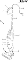
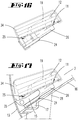
- a vacuum cleaner 1 in the manner of a stick-operated electric hand-held vacuum cleaner with a basic housing 2, which does not contain a motor-blower unit, to which an openable filter chamber 3 for a dust filter bag 4 is connected.
- a handle 5 is fastened to the basic housing 2 to guide the vacuum cleaner 1. At the end, this has a handle 6, which is provided with a switch 7 for electrical start-up and for controlling the vacuum cleaner 1. The electrical supply takes place via an electrical cable 8, which runs into the handle 6.
- the soil cultivation takes place via a floor nozzle 9.
- This is connected to the basic housing 2 and the motor-blower unit arranged therein in terms of flow technology and possibly also electrically via a coupling 10 (not shown in more detail).
- the dust filter bag 4 is held in the filter chamber 3 when the vacuum cleaner 1 is in operation.
- the dust filter bag 4 has a dust bag 12 attached to a holding plate 11.
- the dust bag 12 preferably consists of a fleece.
- the filter chamber 3 can be opened to expose the dust filter bag 4, in particular to enable it to be changed.
- part of the filter chamber 3 is designed as a flap-like cover 13 which can be pivoted about a pivot axis x relative to the fixed part of the filter chamber 3.
- a suction passage opening 14 is formed in the filter chamber 3, through which dirt that is sucked up in the operating state is introduced into the dust filter bag 4 located in the filter chamber 3.
- the dust can be blown or sucked into the dust filter 4.
- the filter chamber 3 is one which, when using the vacuum cleaner 1, is almost vertical or at an acute angle with respect to its longitudinal extension, which is addressed here in the direction of the visible bottom surface 16 to the further surface (not shown) lying above it a vertical can be arranged.
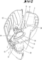
- Registration projections 15 are arranged on the inside of the closure cover 13. Two registration projections 15 spaced apart from one another in the direction of extension of the pivot axis x are preferably provided.
- each registration tab 15 can, as is evident from Figure 2 results to be arranged on the inside of the closure cover 13.
- each registration protrusion 15 is further preferably arranged on the closure cover 13 so as to be pivotable, a pivot axis y of each registration protrusion being preferred 15 runs parallel or at least approximately parallel to the pivot axis x of the closure cover 13.
- the registration projections 15 are arranged to be pivotable about the respective pivot axis independently of one another. The pivoting of one registration protrusion 15 does not necessarily result in the pivoting of the other registration protrusion 15.
- the two registration protrusions 15 can also be designed for improved assembly, for example by forming a connection between the registration protrusions, which connection allows the registration protrusions 15 to be pivoted independently of one another.
- Each registration projection 15 can also be spring-biased into a registration position.
- each registration projection 15 is preferably assigned a spring, for example a leg spring, which loads the registration projection 15 into a preferably stop-limited pivot position, in which the registration projection 15 locks into one in the bottom surface 16 when the closure cover 13 is attempted to be closed without further measures the filter chamber 3 formed blocking formation occurs.
- the blocking configuration can be a shoulder or a projection, for possible interaction with the assignable registration projection 15.
- the blocking configuration is preferably a blocking pocket 17 which extends below the bottom surface 16 and opens in its plane (see also Figure 18 ).
- a lock formation, in particular a lock pocket 17, is assigned to each registration projection 15.
- a deflection of the registration projections 15 is a requirement that they are deflected against the spring force acting on them, so that immersion in the blocking pockets 17 is prevented.
- This deflecting guidance of the registration projections 15 is provided by the area of the holding plate 11 when the dust filter bag 4 is inserted.
- the holding plate 11 is formed like a grid.
- the holding plate 11 can be formed as a molded plastic part.
- the holding plate 11 has an entry opening 18 which is surrounded by a collar 19 which projects into the interior of the dust bag 12.
- the entry opening 18 is in particular switched off by means of a flap-like closure part 20 State of the vacuum cleaner 1, ie closed when the suction air flow is not applied.
- the closure part 20 can be pivoted about an axis, which preferably extends parallel or at least approximately parallel to the pivot axis x of the closure lid 13, from an entry opening closure position into an open position, in which open position the closure part 20 is displaced towards the inside of the bag (cf. For this Figure 7 ).
- the displacement of the closure part 20 into the open position takes place during operation of the vacuum cleaner 1, preferably solely due to the suction air flow acting on it.
- An opening aid which acts mechanically on the closure part 20 and which supports the opening process can also be provided.
- the holding plate 11 projects laterally, here in the width dimension of the filter chamber 3, beyond the dust bag 12.
- the holding plate 11 is formed in its part 23 projecting beyond the dust bag 12 - preferably also for the rest - so that a support on the underside of the dust bag 12 that fills up during operation of the vacuum cleaner 1 can be reached, this, the fastening level E Part 23 of the holding plate 11 receiving on the upper side, as a result of the lattice-like structuring, permits a flow through the air sucked out of the dust bag 12 or blown out of the dust bag 12 depending on the operating mode of the vacuum cleaner 1.
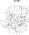
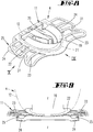
- a lower grip section 24 is formed on the holding plate 11. Two lower gripping sections 24 are preferred on one, the fastening surface 22 for the dust bag 12 at the same time offering basic body of the holding plate 11, as well as the grid-like structured parts 23.
- the lower gripping sections are in a projection in the direction of an entry direction (compare arrow a in Figure 7 ) of the flowing, dust-laden air into the dust bag 12 in at least partial overlap with the respectively assigned part 23 of the holding plate 11 which merges into the fastening surface 22, a distance considered in the entry direction a being provided between the lower gripping section 24 and the associated holding plate part 23 .
- Each lower grip section 24 extends essentially over a fifth of the circumference of the holding plate 11, in particular the circumference of the base body of the holding plate 11. Furthermore, each lower grip section 24 extends approximately starting from a holding plate edge running approximately parallel to the hinge axis of the closure part 20 One third to one half of the length of the narrow side viewed transversely to the longitudinal extent of the holding plate 11 (compare dimension L in Figure 10 ).
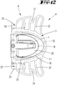
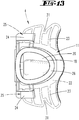
- the lower gripping section 24, the lattice-like structured part 23 and the facing base body section of the holding plate 11 form a U-shaped engagement space 25.
- the mutually facing surfaces of the lower grip section 24 (level F) and the holding plate part 23 (level E) form an acute angle ⁇ of approximately 5 to 10 ° in the longitudinal extent of the lower grip section 24, the Distance in the direction of the section of the holding plate part 23 extending beyond the lower gripping section 24 is evenly reduced.
- a support surface of the lower grip section 24 directed in the direction of the holding plate part 23 also runs at the aforementioned angle to the fastening surface 22 for the dust bag 12.
- the oppositely arranged engagement openings 25 can advantageously be used for removal, moreover in particular for transporting a dust filter bag 4, in particular filled dust filter bag 4, by the user carrying the holding plate 11 into the engagement spaces 25, for example with two fingers. There is no contacting of the dust bag wall, which remains spaced apart from the engagement spaces 25 due to the filter-like structured holding plate part 23.
- the lower gripping sections 24 are further positioned so that they cover the chamber-side locking pockets 17 when the dust filter bag 4 is inserted into the filter chamber 3 (cf. Figure 5 ).
- the holding plate 11 of the dust filter bag 4 is inserted into the filter chamber 3 such that an underside, i.e.
- the circumferential sealing collar 26 of the holding plate 11 facing away from the collar 19 encloses a connecting collar 27 of a suction / blowing nozzle 32 on the device side, which projects into the filter chamber 3.
- the suction / blow connector 32 is completely formed at the end of a suction channel 28 which is guided through the basic housing 2.
- the sealing collar 26 of the holding plate 11 is further provided with a circumferential sealing lip 29, which preferably projects radially inwards over a circumferential edge of the sealing collar 26 for interaction with the connecting collar 27.
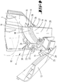
- the holding plate 11 is preferably initially in a pre-assembly position (cf. Figure 4 ).
- the pivoting displacement of the registration protrusions 15 against the spring force is preferably stop-limited (stop protrusion 35), so that the closure cover 13 is completely displaced into the closed position according to FIG Figure 6 a force component acts on the lower gripping sections 24 via the registration projections 15 for (further) displacement of the holding plate 11 into the sealing seat position according to FIG Figure 7 .
- the horizontal basic orientation of the sealing lip 29 changes when it interacts with the outer surface of the connecting collar 27, on which outer surface the sealing lip 29 is finally bent.
- the holding plate 11 is also supported on the bottom surface 16.
- a sealing of the connecting collar 27 against the bottom surface 16 of the filter chamber is provided by a section acting against the bottom of the filter chamber of the connecting collar 27 is reached, which section is molded, for example, as a two-component soft component or surrounds the connecting collar 27 as a separately mounted seal.
- web-like orientation projections 30 are provided on the bottom surface 16, which engage in orientation slots 31 formed in the grid-like structured holding plate part 23.
- Protrusions can also be formed on the holding plate 11, which cooperate with depressions and / or recesses in the receiving space.
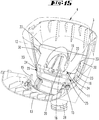
- Figure 15 shows a design of the holding plate 11, in which the holding plate part 23 is formed in a closed area (this area can be broken, for example, to save material), with a holding plate rear grip area 33, which has a width that is greater than the distance between them marginal edges of the orientation projections 30 facing each other.
- the further region of the holding plate part 23 is provided with a width corresponding to this distance or less than this distance.
- blocking ribs projecting upwards beyond the bottom surface 16 can be provided, against which the registration projections 15 block when the dust filter bag 4 is not inserted to step.
- the locking ribs are received by pockets or the like formed on the underside of the lower grip sections 24.
- the dust bag 12 can also be folded into folds on the production side or compactly as a roll (compare Figure 16 ).
- the compact layer is held by one or more, in particular two band-like material strips 34, which at least partially enclose the dust bag 12 and the holding plate 11.
- the material strip 34 can be a paper strip.
- the material strip 34 spans the engagement space 25.
- the tip of the registration protrusion 15 first lies on the surface of the material strip 34. With the continued immersion of the registration protrusion 15 in the engagement space 25, the material strip 34 is overstretched until it finally tears according to plan.
- the fixing action of the material strip (s) 34 is canceled by the lid-closing movement, so that during operation of the vacuum cleaner 1 the dust bag 12 - promoted by the vacuum effect on the dust bag wall - assumes its unfolded / unrolled final size and position.
Landscapes
- Engineering & Computer Science (AREA)
- Mechanical Engineering (AREA)
- Filters For Electric Vacuum Cleaners (AREA)
Applications Claiming Priority (3)
| Application Number | Priority Date | Filing Date | Title |
|---|---|---|---|
| DE102014104081 | 2014-03-25 | ||
| DE102014111248.2A DE102014111248A1 (de) | 2014-03-25 | 2014-08-07 | Staubfilterbeutel für einen Staubsauger sowie Anordnung eines Staubfilterbeutels in einem Staubsauger |
| EP15157713.7A EP2923624B1 (fr) | 2014-03-25 | 2015-03-05 | Sac de filtre à poussière pour un aspirateur et système d'un sac de filtre à poussière dans un aspirateur |
Related Parent Applications (2)
| Application Number | Title | Priority Date | Filing Date |
|---|---|---|---|
| EP15157713.7A Division-Into EP2923624B1 (fr) | 2014-03-25 | 2015-03-05 | Sac de filtre à poussière pour un aspirateur et système d'un sac de filtre à poussière dans un aspirateur |
| EP15157713.7A Division EP2923624B1 (fr) | 2014-03-25 | 2015-03-05 | Sac de filtre à poussière pour un aspirateur et système d'un sac de filtre à poussière dans un aspirateur |
Publications (2)
| Publication Number | Publication Date |
|---|---|
| EP3677159A1 true EP3677159A1 (fr) | 2020-07-08 |
| EP3677159B1 EP3677159B1 (fr) | 2021-06-30 |
Family
ID=52669478
Family Applications (2)
| Application Number | Title | Priority Date | Filing Date |
|---|---|---|---|
| EP20159240.9A Active EP3677159B1 (fr) | 2014-03-25 | 2015-03-05 | Agencement d'un sac filtrant à poussière dans un aspirateur |
| EP15157713.7A Active EP2923624B1 (fr) | 2014-03-25 | 2015-03-05 | Sac de filtre à poussière pour un aspirateur et système d'un sac de filtre à poussière dans un aspirateur |
Family Applications After (1)
| Application Number | Title | Priority Date | Filing Date |
|---|---|---|---|
| EP15157713.7A Active EP2923624B1 (fr) | 2014-03-25 | 2015-03-05 | Sac de filtre à poussière pour un aspirateur et système d'un sac de filtre à poussière dans un aspirateur |
Country Status (5)
| Country | Link |
|---|---|
| EP (2) | EP3677159B1 (fr) |
| JP (1) | JP6674744B2 (fr) |
| CN (1) | CN104939754B (fr) |
| DE (1) | DE102014111248A1 (fr) |
| ES (2) | ES2815569T3 (fr) |
Cited By (1)
| Publication number | Priority date | Publication date | Assignee | Title |
|---|---|---|---|---|
| US20240389808A1 (en) * | 2021-09-14 | 2024-11-28 | Lg Electronics Inc. | Cleaner station |
Families Citing this family (7)
| Publication number | Priority date | Publication date | Assignee | Title |
|---|---|---|---|---|
| DE102016220252A1 (de) * | 2016-10-17 | 2018-04-19 | BSH Hausgeräte GmbH | Staubfilterbeutel für einen Staubsauger |
| EP3318380A1 (fr) * | 2016-11-07 | 2018-05-09 | HILTI Aktiengesellschaft | Reconnaissance de sac filtrant |
| US10779695B2 (en) * | 2017-12-29 | 2020-09-22 | Irobot Corporation | Debris bins and mobile cleaning robots including same |
| CN111067415B (zh) | 2018-10-19 | 2022-07-12 | 德国福维克控股公司 | 带有具有锁止装置的腔盖的抽吸清洁设备 |
| CN111067418A (zh) * | 2018-10-19 | 2020-04-28 | 德国福维克控股公司 | 滤尘袋 |
| JP6639719B2 (ja) * | 2019-03-20 | 2020-02-05 | アイリスオーヤマ株式会社 | 掃除機 |
| KR20220135545A (ko) * | 2021-03-30 | 2022-10-07 | 삼성전자주식회사 | 청소기 |
Citations (5)
| Publication number | Priority date | Publication date | Assignee | Title |
|---|---|---|---|---|
| DE20119853U1 (de) | 2001-08-30 | 2002-03-28 | BSH Bosch und Siemens Hausgeräte GmbH, 81669 München | Staubsauger |
| DE102011075019A1 (de) * | 2011-04-29 | 2012-10-31 | BSH Bosch und Siemens Hausgeräte GmbH | Filtersperre für einen Staubsauger |
| CN102885599A (zh) * | 2012-09-24 | 2013-01-23 | 浙江朝晖过滤技术股份有限公司 | 一种袋式过滤器通用装配组件 |
| DE102012104728A1 (de) | 2012-05-31 | 2013-12-05 | Vorwerk & Co. Interholding Gmbh | Staubfilterbeutel für einen Staubsauger sowie Staubsauger, insbesondere Elektro-Staubsauger |
| DE102013112547A1 (de) | 2012-11-19 | 2014-05-22 | Vorwerk & Co. Interholding Gmbh | Staubfilterbeutel und Staubsauger |
Family Cites Families (18)
| Publication number | Priority date | Publication date | Assignee | Title |
|---|---|---|---|---|
| JPS4531661Y1 (fr) * | 1966-12-16 | 1970-12-04 | ||
| US3675399A (en) * | 1969-04-21 | 1972-07-11 | Whirlpool Co | Vacuum cleaner |
| JPS5086451U (fr) * | 1973-12-11 | 1975-07-23 | ||
| JPS5173866U (fr) * | 1974-12-09 | 1976-06-10 | ||
| JPS62146456U (fr) * | 1986-03-11 | 1987-09-16 | ||
| DE3833799C2 (de) * | 1988-10-05 | 1994-10-06 | Licentia Gmbh | Staubsauger mit einem Filter |
| JP2877736B2 (ja) * | 1995-07-17 | 1999-03-31 | 三洋電機株式会社 | 電気掃除機 |
| JPH09220178A (ja) * | 1996-02-20 | 1997-08-26 | Sanyo Electric Co Ltd | 電気掃除機 |
| FR2750314B1 (fr) * | 1996-06-26 | 1998-10-16 | Laplace Xavier | Filtre a poussieres pour aspirateur et aspirateur ainsi equipe |
| IT1285537B1 (it) * | 1996-10-22 | 1998-06-08 | Gisowatt Spa Ind Elettrodomest | Sacchetto raccogli-polvere per scope elettriche e simili a chiusura automatica |
| JP2002112935A (ja) * | 2001-09-26 | 2002-04-16 | Sanyo Electric Co Ltd | 電気掃除機 |
| DE10248087B4 (de) * | 2002-10-15 | 2011-05-19 | BSH Bosch und Siemens Hausgeräte GmbH | Staubsauger mit einem entnehmbaren Staubsammelbehälter |
| JP4222102B2 (ja) * | 2003-05-19 | 2009-02-12 | パナソニック株式会社 | 電気掃除機 |
| DE102004030346A1 (de) * | 2004-06-18 | 2006-01-05 | Branofilter Gmbh | Staubfilterbeutel und zugeordnete Adapterplatte |
| CN101313831A (zh) * | 2007-05-31 | 2008-12-03 | 乐金电子(天津)电器有限公司 | 吸尘器的集尘袋固定结构 |
| DE102008046200B4 (de) * | 2007-09-28 | 2016-09-15 | Vorwerk & Co. Interholding Gmbh | Filterbeutel für einen Staubsauger |
| JP2012223224A (ja) * | 2011-04-15 | 2012-11-15 | Panasonic Corp | 電気掃除機 |
| DE102013101991A1 (de) * | 2013-02-28 | 2014-08-28 | Wolf Pvg Gmbh & Co. Kg | Filterbeutel für einen Staubsauger |
-
2014
- 2014-08-07 DE DE102014111248.2A patent/DE102014111248A1/de not_active Withdrawn
-
2015
- 2015-02-26 JP JP2015036109A patent/JP6674744B2/ja not_active Expired - Fee Related
- 2015-03-05 ES ES15157713T patent/ES2815569T3/es active Active
- 2015-03-05 EP EP20159240.9A patent/EP3677159B1/fr active Active
- 2015-03-05 ES ES20159240T patent/ES2886042T3/es active Active
- 2015-03-05 EP EP15157713.7A patent/EP2923624B1/fr active Active
- 2015-03-25 CN CN201510131704.7A patent/CN104939754B/zh active Active
Patent Citations (6)
| Publication number | Priority date | Publication date | Assignee | Title |
|---|---|---|---|---|
| DE20119853U1 (de) | 2001-08-30 | 2002-03-28 | BSH Bosch und Siemens Hausgeräte GmbH, 81669 München | Staubsauger |
| DE102011075019A1 (de) * | 2011-04-29 | 2012-10-31 | BSH Bosch und Siemens Hausgeräte GmbH | Filtersperre für einen Staubsauger |
| DE102012104728A1 (de) | 2012-05-31 | 2013-12-05 | Vorwerk & Co. Interholding Gmbh | Staubfilterbeutel für einen Staubsauger sowie Staubsauger, insbesondere Elektro-Staubsauger |
| CN102885599A (zh) * | 2012-09-24 | 2013-01-23 | 浙江朝晖过滤技术股份有限公司 | 一种袋式过滤器通用装配组件 |
| DE112013003872T5 (de) * | 2012-09-24 | 2015-05-07 | Zhejiang Zhaohui Filtration Technology Co., Ltd | Allgemeine Montagekomponente eines Beutelfilters |
| DE102013112547A1 (de) | 2012-11-19 | 2014-05-22 | Vorwerk & Co. Interholding Gmbh | Staubfilterbeutel und Staubsauger |
Cited By (1)
| Publication number | Priority date | Publication date | Assignee | Title |
|---|---|---|---|---|
| US20240389808A1 (en) * | 2021-09-14 | 2024-11-28 | Lg Electronics Inc. | Cleaner station |
Also Published As
| Publication number | Publication date |
|---|---|
| CN104939754B (zh) | 2019-02-22 |
| ES2886042T3 (es) | 2021-12-16 |
| EP2923624B1 (fr) | 2020-08-05 |
| EP2923624A3 (fr) | 2016-02-17 |
| ES2815569T3 (es) | 2021-03-30 |
| JP6674744B2 (ja) | 2020-04-01 |
| EP2923624A2 (fr) | 2015-09-30 |
| EP3677159B1 (fr) | 2021-06-30 |
| CN104939754A (zh) | 2015-09-30 |
| JP2015181934A (ja) | 2015-10-22 |
| DE102014111248A1 (de) | 2015-10-01 |
Similar Documents
| Publication | Publication Date | Title |
|---|---|---|
| EP2923624B1 (fr) | Sac de filtre à poussière pour un aspirateur et système d'un sac de filtre à poussière dans un aspirateur | |
| DE112012000251B4 (de) | Staubbehälter für Staubsauger | |
| DE102010038095B4 (de) | Entleerungsstation für einen akkumulatorbetriebenen Elektrostaubsauger | |
| EP2866631B1 (fr) | Combinaison d'un mini-aspirateur et d'un boîtier d'aspirateur ainsi que mini-aspirateur et boîtier d'aspirateur | |
| EP1917897B1 (fr) | Pièce de raccordement pour un sac antipoussière ainsi que sac antipoussière doté d'une telle pièce de raccordement | |
| EP3546133B1 (fr) | Dispositif de collecte de poussière doté d'un agencement de support | |
| WO2014001492A1 (fr) | Combinaison d'un mini-aspirateur et d'un châssis d'aspirateur-balai en un aspirateur-balai | |
| EP2281497B1 (fr) | Dispositif de filtre pour un aspirateur | |
| DE102008034458B4 (de) | Handgeführte Saugdüse zum Anschluss an einen Staubsauger und Saugdüse trennbar mit einem Düsenvorsatz | |
| DE112014005262B4 (de) | Bürstenaufsatz für Staubsaugerdüsen | |
| DE69904809T2 (de) | Elektrischer apparat zur aufnahme von abfällen | |
| DE102009034955B4 (de) | Selbsttätig verfahrbares Bodenstaub-Aufsammelgerät | |
| DE102019128051B4 (de) | Saugreinigungsgerät mit einem eine Filterkammer verschließenden Kammerdeckel | |
| EP0655217B1 (fr) | Aspirateur avec conteneur pour sac à poussières | |
| BE1022268B1 (de) | Staubfilterbeutel fur einen staubsauger sowie staubsauger, insbesondere elektro-staubsauger | |
| EP2866632B1 (fr) | Combinaison composée d'un mini-aspirateur et d'un bâti d'aspirateur-balai, ainsi que mini-aspirateur et bâti d'aspirateur-balai | |
| EP2025279B1 (fr) | Sac filtrant doté d'une plaque de support | |
| EP2201877B9 (fr) | Procédé de fonctionnement d'un aspirateur, ainsi qu'aspirateur à moteur électrique et réservoir de matériau de filtre en forme de tuyau | |
| DE102013104255A1 (de) | Verfahren zum Betrieb einer Staubsammelkammer sowie Staubsammelkammer für einen elektrisch betriebenen Staubsauger | |
| DE102006037456A1 (de) | Filterbeutel für einen Staubsauger | |
| DE102019125704B4 (de) | Auswechselbarer Akkumulator | |
| DE102015113460A1 (de) | Bodendüse für ein Reinigungsgerät, insbesondere für einen Staubsauger | |
| DE4341248A1 (de) | Staubfilterbeutel für einen Staubsauger | |
| DE102015118649B4 (de) | Vorrichtung zum Verbinden eines elektrischen Kupplungselementes | |
| DE102019128050B4 (de) | Saugreinigungsgerät mit einem eine Sperreinrichtung aufweisenden Kammerdeckel |
Legal Events
| Date | Code | Title | Description |
|---|---|---|---|
| PUAI | Public reference made under article 153(3) epc to a published international application that has entered the european phase |
Free format text: ORIGINAL CODE: 0009012 |
|
| STAA | Information on the status of an ep patent application or granted ep patent |
Free format text: STATUS: THE APPLICATION HAS BEEN PUBLISHED |
|
| AC | Divisional application: reference to earlier application |
Ref document number: 2923624 Country of ref document: EP Kind code of ref document: P |
|
| AK | Designated contracting states |
Kind code of ref document: A1 Designated state(s): AL AT BE BG CH CY CZ DE DK EE ES FI FR GB GR HR HU IE IS IT LI LT LU LV MC MK MT NL NO PL PT RO RS SE SI SK SM TR |
|
| STAA | Information on the status of an ep patent application or granted ep patent |
Free format text: STATUS: REQUEST FOR EXAMINATION WAS MADE |
|
| 17P | Request for examination filed |
Effective date: 20200807 |
|
| RBV | Designated contracting states (corrected) |
Designated state(s): AL AT BE BG CH CY CZ DE DK EE ES FI FR GB GR HR HU IE IS IT LI LT LU LV MC MK MT NL NO PL PT RO RS SE SI SK SM TR |
|
| GRAP | Despatch of communication of intention to grant a patent |
Free format text: ORIGINAL CODE: EPIDOSNIGR1 |
|
| STAA | Information on the status of an ep patent application or granted ep patent |
Free format text: STATUS: GRANT OF PATENT IS INTENDED |
|
| RIC1 | Information provided on ipc code assigned before grant |
Ipc: A47L 9/14 20060101AFI20201218BHEP |
|
| INTG | Intention to grant announced |
Effective date: 20210125 |
|
| RIN1 | Information on inventor provided before grant (corrected) |
Inventor name: LAPP, OLIVER Inventor name: RODE, GERRIT Inventor name: DIEUDONNE, STEPHAN PETER |
|
| GRAS | Grant fee paid |
Free format text: ORIGINAL CODE: EPIDOSNIGR3 |
|
| GRAA | (expected) grant |
Free format text: ORIGINAL CODE: 0009210 |
|
| STAA | Information on the status of an ep patent application or granted ep patent |
Free format text: STATUS: THE PATENT HAS BEEN GRANTED |
|
| AC | Divisional application: reference to earlier application |
Ref document number: 2923624 Country of ref document: EP Kind code of ref document: P |
|
| AK | Designated contracting states |
Kind code of ref document: B1 Designated state(s): AL AT BE BG CH CY CZ DE DK EE ES FI FR GB GR HR HU IE IS IT LI LT LU LV MC MK MT NL NO PL PT RO RS SE SI SK SM TR |
|
| REG | Reference to a national code |
Ref country code: CH Ref legal event code: EP |
|
| REG | Reference to a national code |
Ref country code: AT Ref legal event code: REF Ref document number: 1405555 Country of ref document: AT Kind code of ref document: T Effective date: 20210715 |
|
| REG | Reference to a national code |
Ref country code: DE Ref legal event code: R096 Ref document number: 502015014891 Country of ref document: DE |
|
| REG | Reference to a national code |
Ref country code: IE Ref legal event code: FG4D Free format text: LANGUAGE OF EP DOCUMENT: GERMAN |
|
| REG | Reference to a national code |
Ref country code: LT Ref legal event code: MG9D |
|
| PG25 | Lapsed in a contracting state [announced via postgrant information from national office to epo] |
Ref country code: BG Free format text: LAPSE BECAUSE OF FAILURE TO SUBMIT A TRANSLATION OF THE DESCRIPTION OR TO PAY THE FEE WITHIN THE PRESCRIBED TIME-LIMIT Effective date: 20210930 Ref country code: FI Free format text: LAPSE BECAUSE OF FAILURE TO SUBMIT A TRANSLATION OF THE DESCRIPTION OR TO PAY THE FEE WITHIN THE PRESCRIBED TIME-LIMIT Effective date: 20210630 Ref country code: HR Free format text: LAPSE BECAUSE OF FAILURE TO SUBMIT A TRANSLATION OF THE DESCRIPTION OR TO PAY THE FEE WITHIN THE PRESCRIBED TIME-LIMIT Effective date: 20210630 |
|
| REG | Reference to a national code |
Ref country code: NL Ref legal event code: MP Effective date: 20210630 |
|
| PG25 | Lapsed in a contracting state [announced via postgrant information from national office to epo] |
Ref country code: RS Free format text: LAPSE BECAUSE OF FAILURE TO SUBMIT A TRANSLATION OF THE DESCRIPTION OR TO PAY THE FEE WITHIN THE PRESCRIBED TIME-LIMIT Effective date: 20210630 Ref country code: SE Free format text: LAPSE BECAUSE OF FAILURE TO SUBMIT A TRANSLATION OF THE DESCRIPTION OR TO PAY THE FEE WITHIN THE PRESCRIBED TIME-LIMIT Effective date: 20210630 Ref country code: NO Free format text: LAPSE BECAUSE OF FAILURE TO SUBMIT A TRANSLATION OF THE DESCRIPTION OR TO PAY THE FEE WITHIN THE PRESCRIBED TIME-LIMIT Effective date: 20210930 Ref country code: LV Free format text: LAPSE BECAUSE OF FAILURE TO SUBMIT A TRANSLATION OF THE DESCRIPTION OR TO PAY THE FEE WITHIN THE PRESCRIBED TIME-LIMIT Effective date: 20210630 Ref country code: GR Free format text: LAPSE BECAUSE OF FAILURE TO SUBMIT A TRANSLATION OF THE DESCRIPTION OR TO PAY THE FEE WITHIN THE PRESCRIBED TIME-LIMIT Effective date: 20211001 |
|
| REG | Reference to a national code |
Ref country code: ES Ref legal event code: FG2A Ref document number: 2886042 Country of ref document: ES Kind code of ref document: T3 Effective date: 20211216 |
|
| PG25 | Lapsed in a contracting state [announced via postgrant information from national office to epo] |
Ref country code: CZ Free format text: LAPSE BECAUSE OF FAILURE TO SUBMIT A TRANSLATION OF THE DESCRIPTION OR TO PAY THE FEE WITHIN THE PRESCRIBED TIME-LIMIT Effective date: 20210630 Ref country code: NL Free format text: LAPSE BECAUSE OF FAILURE TO SUBMIT A TRANSLATION OF THE DESCRIPTION OR TO PAY THE FEE WITHIN THE PRESCRIBED TIME-LIMIT Effective date: 20210630 Ref country code: PT Free format text: LAPSE BECAUSE OF FAILURE TO SUBMIT A TRANSLATION OF THE DESCRIPTION OR TO PAY THE FEE WITHIN THE PRESCRIBED TIME-LIMIT Effective date: 20211102 Ref country code: RO Free format text: LAPSE BECAUSE OF FAILURE TO SUBMIT A TRANSLATION OF THE DESCRIPTION OR TO PAY THE FEE WITHIN THE PRESCRIBED TIME-LIMIT Effective date: 20210630 Ref country code: SM Free format text: LAPSE BECAUSE OF FAILURE TO SUBMIT A TRANSLATION OF THE DESCRIPTION OR TO PAY THE FEE WITHIN THE PRESCRIBED TIME-LIMIT Effective date: 20210630 Ref country code: EE Free format text: LAPSE BECAUSE OF FAILURE TO SUBMIT A TRANSLATION OF THE DESCRIPTION OR TO PAY THE FEE WITHIN THE PRESCRIBED TIME-LIMIT Effective date: 20210630 Ref country code: SK Free format text: LAPSE BECAUSE OF FAILURE TO SUBMIT A TRANSLATION OF THE DESCRIPTION OR TO PAY THE FEE WITHIN THE PRESCRIBED TIME-LIMIT Effective date: 20210630 |
|
| PG25 | Lapsed in a contracting state [announced via postgrant information from national office to epo] |
Ref country code: PL Free format text: LAPSE BECAUSE OF FAILURE TO SUBMIT A TRANSLATION OF THE DESCRIPTION OR TO PAY THE FEE WITHIN THE PRESCRIBED TIME-LIMIT Effective date: 20210630 |
|
| REG | Reference to a national code |
Ref country code: DE Ref legal event code: R097 Ref document number: 502015014891 Country of ref document: DE |
|
| PG25 | Lapsed in a contracting state [announced via postgrant information from national office to epo] |
Ref country code: DK Free format text: LAPSE BECAUSE OF FAILURE TO SUBMIT A TRANSLATION OF THE DESCRIPTION OR TO PAY THE FEE WITHIN THE PRESCRIBED TIME-LIMIT Effective date: 20210630 |
|
| PLBE | No opposition filed within time limit |
Free format text: ORIGINAL CODE: 0009261 |
|
| STAA | Information on the status of an ep patent application or granted ep patent |
Free format text: STATUS: NO OPPOSITION FILED WITHIN TIME LIMIT |
|
| PG25 | Lapsed in a contracting state [announced via postgrant information from national office to epo] |
Ref country code: AL Free format text: LAPSE BECAUSE OF FAILURE TO SUBMIT A TRANSLATION OF THE DESCRIPTION OR TO PAY THE FEE WITHIN THE PRESCRIBED TIME-LIMIT Effective date: 20210630 |
|
| 26N | No opposition filed |
Effective date: 20220331 |
|
| PG25 | Lapsed in a contracting state [announced via postgrant information from national office to epo] |
Ref country code: MC Free format text: LAPSE BECAUSE OF FAILURE TO SUBMIT A TRANSLATION OF THE DESCRIPTION OR TO PAY THE FEE WITHIN THE PRESCRIBED TIME-LIMIT Effective date: 20210630 |
|
| REG | Reference to a national code |
Ref country code: CH Ref legal event code: PL |
|
| GBPC | Gb: european patent ceased through non-payment of renewal fee |
Effective date: 20220305 |
|
| REG | Reference to a national code |
Ref country code: BE Ref legal event code: MM Effective date: 20220331 |
|
| PG25 | Lapsed in a contracting state [announced via postgrant information from national office to epo] |
Ref country code: LU Free format text: LAPSE BECAUSE OF NON-PAYMENT OF DUE FEES Effective date: 20220305 Ref country code: LI Free format text: LAPSE BECAUSE OF NON-PAYMENT OF DUE FEES Effective date: 20220331 Ref country code: IE Free format text: LAPSE BECAUSE OF NON-PAYMENT OF DUE FEES Effective date: 20220305 Ref country code: GB Free format text: LAPSE BECAUSE OF NON-PAYMENT OF DUE FEES Effective date: 20220305 Ref country code: CH Free format text: LAPSE BECAUSE OF NON-PAYMENT OF DUE FEES Effective date: 20220331 |
|
| PG25 | Lapsed in a contracting state [announced via postgrant information from national office to epo] |
Ref country code: BE Free format text: LAPSE BECAUSE OF NON-PAYMENT OF DUE FEES Effective date: 20220331 |
|
| PG25 | Lapsed in a contracting state [announced via postgrant information from national office to epo] |
Ref country code: LT Free format text: LAPSE BECAUSE OF FAILURE TO SUBMIT A TRANSLATION OF THE DESCRIPTION OR TO PAY THE FEE WITHIN THE PRESCRIBED TIME-LIMIT Effective date: 20210630 |
|
| REG | Reference to a national code |
Ref country code: AT Ref legal event code: MM01 Ref document number: 1405555 Country of ref document: AT Kind code of ref document: T Effective date: 20220305 |
|
| P01 | Opt-out of the competence of the unified patent court (upc) registered |
Effective date: 20230517 |
|
| PG25 | Lapsed in a contracting state [announced via postgrant information from national office to epo] |
Ref country code: AT Free format text: LAPSE BECAUSE OF NON-PAYMENT OF DUE FEES Effective date: 20220305 |
|
| PG25 | Lapsed in a contracting state [announced via postgrant information from national office to epo] |
Ref country code: MK Free format text: LAPSE BECAUSE OF FAILURE TO SUBMIT A TRANSLATION OF THE DESCRIPTION OR TO PAY THE FEE WITHIN THE PRESCRIBED TIME-LIMIT Effective date: 20210630 Ref country code: CY Free format text: LAPSE BECAUSE OF FAILURE TO SUBMIT A TRANSLATION OF THE DESCRIPTION OR TO PAY THE FEE WITHIN THE PRESCRIBED TIME-LIMIT Effective date: 20210630 |
|
| PG25 | Lapsed in a contracting state [announced via postgrant information from national office to epo] |
Ref country code: HU Free format text: LAPSE BECAUSE OF FAILURE TO SUBMIT A TRANSLATION OF THE DESCRIPTION OR TO PAY THE FEE WITHIN THE PRESCRIBED TIME-LIMIT; INVALID AB INITIO Effective date: 20150305 |
|
| PG25 | Lapsed in a contracting state [announced via postgrant information from national office to epo] |
Ref country code: MT Free format text: LAPSE BECAUSE OF FAILURE TO SUBMIT A TRANSLATION OF THE DESCRIPTION OR TO PAY THE FEE WITHIN THE PRESCRIBED TIME-LIMIT Effective date: 20210630 |
|
| PG25 | Lapsed in a contracting state [announced via postgrant information from national office to epo] |
Ref country code: TR Free format text: LAPSE BECAUSE OF FAILURE TO SUBMIT A TRANSLATION OF THE DESCRIPTION OR TO PAY THE FEE WITHIN THE PRESCRIBED TIME-LIMIT Effective date: 20210630 |
|
| PGFP | Annual fee paid to national office [announced via postgrant information from national office to epo] |
Ref country code: DE Payment date: 20260320 Year of fee payment: 12 |
|
| PGFP | Annual fee paid to national office [announced via postgrant information from national office to epo] |
Ref country code: FR Payment date: 20260325 Year of fee payment: 12 |
|
| PGFP | Annual fee paid to national office [announced via postgrant information from national office to epo] |
Ref country code: ES Payment date: 20260420 Year of fee payment: 12 |
|
| PGFP | Annual fee paid to national office [announced via postgrant information from national office to epo] |
Ref country code: IT Payment date: 20260331 Year of fee payment: 12 |