EP3677313A1 - Masque de pollution et procédé de commande - Google Patents
Masque de pollution et procédé de commande Download PDFInfo
- Publication number
- EP3677313A1 EP3677313A1 EP19150499.2A EP19150499A EP3677313A1 EP 3677313 A1 EP3677313 A1 EP 3677313A1 EP 19150499 A EP19150499 A EP 19150499A EP 3677313 A1 EP3677313 A1 EP 3677313A1
- Authority
- EP
- European Patent Office
- Prior art keywords
- fan
- mask
- rotation speed
- speed
- value
- Prior art date
- Legal status (The legal status is an assumption and is not a legal conclusion. Google has not performed a legal analysis and makes no representation as to the accuracy of the status listed.)
- Withdrawn
Links
- 238000000034 method Methods 0.000 title claims description 18
- 230000029058 respiratory gaseous exchange Effects 0.000 claims abstract description 77
- 230000008859 change Effects 0.000 claims abstract description 19
- 238000005070 sampling Methods 0.000 claims description 5
- 238000002560 therapeutic procedure Methods 0.000 claims description 5
- 230000003247 decreasing effect Effects 0.000 claims description 4
- 230000007613 environmental effect Effects 0.000 abstract description 7
- 239000003570 air Substances 0.000 description 72
- 230000000694 effects Effects 0.000 description 9
- 238000012544 monitoring process Methods 0.000 description 9
- 238000013461 design Methods 0.000 description 8
- 238000001914 filtration Methods 0.000 description 7
- 230000001276 controlling effect Effects 0.000 description 5
- 238000005259 measurement Methods 0.000 description 5
- 230000008901 benefit Effects 0.000 description 4
- 239000012080 ambient air Substances 0.000 description 3
- 238000009499 grossing Methods 0.000 description 3
- 238000013459 approach Methods 0.000 description 2
- 230000001174 ascending effect Effects 0.000 description 2
- 238000009530 blood pressure measurement Methods 0.000 description 2
- 238000004140 cleaning Methods 0.000 description 2
- 238000009833 condensation Methods 0.000 description 2
- 230000005494 condensation Effects 0.000 description 2
- 238000001816 cooling Methods 0.000 description 2
- 230000001419 dependent effect Effects 0.000 description 2
- 239000000463 material Substances 0.000 description 2
- 238000011017 operating method Methods 0.000 description 2
- 230000008569 process Effects 0.000 description 2
- 230000009467 reduction Effects 0.000 description 2
- 230000001105 regulatory effect Effects 0.000 description 2
- 230000004044 response Effects 0.000 description 2
- 238000009423 ventilation Methods 0.000 description 2
- 206010013975 Dyspnoeas Diseases 0.000 description 1
- 206010019345 Heat stroke Diseases 0.000 description 1
- 238000003915 air pollution Methods 0.000 description 1
- 238000003491 array Methods 0.000 description 1
- 238000009529 body temperature measurement Methods 0.000 description 1
- 238000004364 calculation method Methods 0.000 description 1
- 239000000356 contaminant Substances 0.000 description 1
- 238000001514 detection method Methods 0.000 description 1
- 239000003344 environmental pollutant Substances 0.000 description 1
- 239000004744 fabric Substances 0.000 description 1
- 230000036541 health Effects 0.000 description 1
- 230000006872 improvement Effects 0.000 description 1
- 210000004072 lung Anatomy 0.000 description 1
- 239000012528 membrane Substances 0.000 description 1
- 230000008520 organization Effects 0.000 description 1
- 239000013618 particulate matter Substances 0.000 description 1
- 231100000614 poison Toxicity 0.000 description 1
- 231100000719 pollutant Toxicity 0.000 description 1
- 238000011045 prefiltration Methods 0.000 description 1
- 230000002035 prolonged effect Effects 0.000 description 1
- 239000004753 textile Substances 0.000 description 1
- 239000003440 toxic substance Substances 0.000 description 1
- 238000013022 venting Methods 0.000 description 1
- XLYOFNOQVPJJNP-UHFFFAOYSA-N water Substances O XLYOFNOQVPJJNP-UHFFFAOYSA-N 0.000 description 1
Images


Classifications
-
- A—HUMAN NECESSITIES
- A62—LIFE-SAVING; FIRE-FIGHTING
- A62B—DEVICES, APPARATUS OR METHODS FOR LIFE-SAVING
- A62B18/00—Breathing masks or helmets, e.g. affording protection against chemical agents or for use at high altitudes or incorporating a pump or compressor for reducing the inhalation effort
- A62B18/006—Breathing masks or helmets, e.g. affording protection against chemical agents or for use at high altitudes or incorporating a pump or compressor for reducing the inhalation effort with pumps for forced ventilation
-
- A—HUMAN NECESSITIES
- A61—MEDICAL OR VETERINARY SCIENCE; HYGIENE
- A61B—DIAGNOSIS; SURGERY; IDENTIFICATION
- A61B5/00—Measuring for diagnostic purposes; Identification of persons
- A61B5/08—Measuring devices for evaluating the respiratory organs
- A61B5/0816—Measuring devices for examining respiratory frequency
-
- A—HUMAN NECESSITIES
- A61—MEDICAL OR VETERINARY SCIENCE; HYGIENE
- A61B—DIAGNOSIS; SURGERY; IDENTIFICATION
- A61B5/00—Measuring for diagnostic purposes; Identification of persons
- A61B5/08—Measuring devices for evaluating the respiratory organs
- A61B5/087—Measuring breath flow
- A61B5/09—Measuring breath flow using an element rotated by the flow
Definitions
- This invention relates to a pollution mask, for providing filtered air to the wearer of the mask, with the flow assisted by a fan.
- the World Health Organization estimates that 4 million people die from air pollution every year. Part of this problem is the outdoor air quality in cities. The worst in class are Indian cities like Delhi that have an annual pollution level more than 10 times the recommended level. Well known is Beijing with an annual average 8.5 times the recommended safe levels. However, even in European cities like London, Paris and Berlin, the levels are higher than recommended by the WHO.
- the benefit to the wearer of using a powered mask is that the lungs are relieved of the slight strain caused by inhalation against the resistance of the filters in a conventional non-powered mask.
- a powered mask delivers a steady stream of air to the face and may for example provide a slight positive pressure, which may be determined by the resistance of an exhale valve, to ensure that any leakage is outward rather than inward.
- the pressure inside the mask can be measured and both pressure as well as pressure variation can be used to control the fan.
- the pressure inside a mask can be measured by a pressure sensor and the fan speed can be varied in dependence on the sensor measurements.
- a pressure sensor is costly so it would be desirable to provide an alternative method of monitoring pressure inside a mask.
- the applicant has also proposed, but not yet published, a solution in which the inner mask environment (temperature and relative humidity) is used as an indicator for use in controlling the fan speed.
- sensors in the mask chamber are susceptible to error due to condensation which may deteriorate the sensor response.
- the response of a temperature and humidity sensor is generally slow so may not be able to track changes at the required rate.
- the change in temperature detected between breathing in and breathing out is also small in hot weather conditions.
- a pollution mask comprising:
- This mask provides automatic adjustment of the fan speed based on the fan rotation speed and the external temperature. By taking the external temperature into account, an estimate of user comfort is made.
- the fan speed adjustment is able to provide different air flows under different environmental conditions (temperature) and for different levels of activity of the user. Taking fast walking for example, users may need a large air flow to help to manage the climate in the mask during the summer, whereas relatively less air flow is needed in the winter in order to avoid making the wearer cold.
- the use of ambient temperature measurement, i.e. outside the mask chamber avoids water condensation issues.
- the first and second values enable user activities to be taken into account.
- the first value for example relates to a depth of breathing, and by this is meant there is a positive correlation between the first value and the depth of breathing. More generally, the first value may for example relate to (i.e. correlate with) a magnitude of a pressure fluctuation across the fan. The pressure fluctuations are caused by breathing when the mask is worn and in normal use.
- the second value has a positive correlation with the rate of breathing. This may be used as another indicator of the activity level of the user, in addition to the depth of breathing as indicated by the first value.
- the invention relates to a pollution mask.
- a pollution mask By this is meant a device which has the primary purpose of filtering ambient air to be breathed by the user.
- the mask does not perform any form of patient treatment.
- the pressure levels and flows resulting from the fan operation are intended solely to assist in providing comfort (by influencing the temperature or relative humidity in the air chamber) and/or to assist in providing a flow across a filter without requiring significant additional breathing effort by the user.
- the mask does not provide overall breathing assistance compared to a condition in which the user does not wear the mask.
- fan speed monitoring is also used instead of having pressure measurement.
- the fan itself may be used so that no additional sensors are required.
- the chamber may be closed in normal use, so that pressure fluctuations in the chamber have an influence on the load conditions of the fan and hence alter the fan electrical characteristics.
- the fan electrical characteristics may determine the nature of the chamber, for example its volume, and if it is an open or closed volume.
- the first value is for example based on a maximum swing in fan rotation speed during a sampling window. This swing is representative of the degree of pressure fluctuation, and hence it relates to the depth of breathing.
- the second value is for example a frequency based on the time between a consecutive maxima and minima in the fan rotation speed. This time period corresponds to half the breathing period, hence a frequency directly derived from this value corresponds to double the breathing rate (i.e. frequency).
- the sampling window is chosen to be sufficient to capture at least one full breathing cycle, for example 6 seconds to capture a full breathing cycle at the lowest breathing rate of 10 breaths per minute.
- the filter for example forms a boundary directly between the air chamber and the ambient surroundings outside the air chamber. This provides a compact arrangement which avoids the need for flow transport passageways. It means the user is able to breathe in through the filter.
- the filter may have multiple layers. For example, an outer layer may form the body of the mask (for example a fabric layer), and an inner layer may be for removing finer pollutants. The inner layer may then be removable for cleaning or replacement, but both layers may together be considered to constitute the filter, in that air is able to pass through the structure and the structure performs a filtering function.
- the filter thus preferably comprises an outer wall of the air chamber and optionally one or more further filter layers. This provides a particularly compact arrangement and enables a large filter area, because the mask body performs the filtering function. The ambient air is thus provided directly to the user, when the user breathes in, through the filter.
- the pressure may be positive or negative (compared to the ambient pressure), for example if the fan is off there will be negative pressure caused by inhalation and a positive pressure caused by exhalation. If an exhaust fan is on, negative or positive pressures are possible during breathing depending on the fan speed and breathing characteristics. A negative pressure will result during periods of no breathing.
- the fan is for providing an increased pressure in the air chamber (e.g. a flow into the air chamber during inhalation), it is only required to provide a small increased pressure, for example for assisting inhalation of the user.
- a maximum pressure in the air chamber in use is for example below 4 cmH 2 O, for example below 2 cmH 2 O, for example below 1 cmH 2 O, higher than the pressure outside the air chamber.
- the mask may further comprise a humidity sensor for measuring an ambient humidity level outside the air chamber, wherein the controller is adapted to set a fan speed further in dependence on the humidity level.
- a humidity sensor for measuring an ambient humidity level outside the air chamber
- the controller is adapted to set a fan speed further in dependence on the humidity level.
- the controller may be adapted to: derive from the ambient temperature and the ambient humidity level a heat index value which relates to a measure of comfort.
- This heat index value is representative of the general ambient environmental conditions and can be used so that the fan speed is set taking into account the expected user comfort in those particular conditions.
- the heat index value may comprise a polynomial function of the ambient temperature, the ambient humidity level and one or more powers of the ambient temperature and/or ambient humidity level. For example, it may comprise a function of the ambient temperature, the square of the ambient temperature, the ambient humidity level and the square of the ambient humidity level.
- the controller may be adapted to: generate from the current fan rotation speed and the first and second values an instruction to increase the fan speed, decrease the fan speed or keep the fan speed the same.
- the depth and rate of breathing are used to control whether a change in fan speed is needed, taking into account the current fan speed.
- the controller may be adapted to: determine from the ambient temperature and the ambient humidity level an amount by which the fan speed should be increased or decreased.
- the environmental conditions determine the amount by which a fan speed adjustment is needed.
- the controller may be adapted to determine from the fan rotation speed or change in fan rotation speed that the mask is not worn to turn off the fan if it is determined that the mask is not worn.
- the fan rotation signal may be analyzed. This may take account both of the first value, which is indicative of the depth of breathing (when breathing is detected), as well as the second value, which is indicative of the breathing rate (when breathing is detected).
- the mask design By determining if the mask is worn, the mask design enables power to be saved when the mask is not being worn, but without requiring any additional sensors. In particular, if there is no detected pressure differential across the mask, this indicates that both sides are at atmospheric pressure and the mask is not being worn. In effect, there is no longer a closed or partially closed chamber, so that the air chamber is open to the atmosphere. The fan may be turned off if it is detected that the mask is not worn.
- the fan may be driven by an electronically commutated brushless motor, and the means for determining rotation speed comprises an internal sensor of the motor.
- the means for determining rotation speed may comprise a circuit for detecting a ripple on the electrical supply to a motor which drives the fan.
- An internal sensor is already provided in such motors to enable rotation of the motor.
- the motor may even have an output port on which the internal sensor output is provided.
- a ripple is detected which results from switching current through the motor coils, which cause induced changes in the supply voltage as a result of the finite impedance of the input voltage source.
- the fan may be a two-wire fan and the circuit for detecting a ripple comprises a high pass filter.
- the additional circuitry needed for a motor which does not already have a suitable fan speed output can be kept to a minimum.
- the controller may be adapted to:
- the rotation monitoring thus provides a simple way to determine inhalation phases, which may then be used to control the timing of a venting valve of the mask or to determine whether or not the mask is worn and hence in use.
- the controller may be adapted to turn off the fan during an inhalation time. This may be used to save power. Shutting down the fan during inhalation may be desirable for a user who does not have difficulty breathing through the filter, to save power if configured in such a way.
- the fan may be only for drawing air from inside the air chamber to the outside. In this way, it may at the same promote a supply of fresh filtered air to the air chamber even during exhalation, which improves user comfort.
- the pressure in the air chamber may be below the outside (atmospheric) pressure at all times so that fresh air is always supplied to the face.
- the outlet valve may comprise a passive pressure-regulated check valve or an actively driven electrically controllable valve. This may be used to make the mask more comfortable. During inhalation, by closing the valve (actively or passively), it is prevented that unfiltered air is drawn in. During exhalation, the valve is opened so that breathed out air is expelled.
- the invention also provides a non-therapeutic method of controlling a pollution mask, wherein the pollution mask is not a mask for delivering therapy to a patient, the method comprising:
- the method may additionally comprise measuring an ambient humidity level outside the air chamber, and setting a fan speed is further in dependence on the humidity level.
- a heat index value may be derived from the temperature and humidity measurements, which relates to a measure of comfort.
- the method may comprise:
- the invention provides a pollution mask having a driven fan, wherein a rotation speed of the fan is monitored, as well as external temperature and optionally also humidity levels.
- the fan rotation speed or change in fan rotation speed is used to obtain a first value which relates to a depth of breathing and a second value which relates to a rate of breathing. These are used, in combination with the ambient temperature and optionally the ambient humidity level, to set the fan speed.
- the fan speed is set taking into account the breathing characteristics of the user as well as the ambient environmental conditions.
- Figure 1 shows a face mask with automatic fan speed control.
- a subject 10 is shown wearing a face mask 12 which covers the nose and mouth of the subject.
- the purpose of the mask is to filter air before it is breathed in the subject.
- the mask body itself acts as an air filter 16. Air is drawn in to an air chamber 18 formed by the mask by inhalation. During inhalation, an outlet valve 22 such as a check valve is closed due to the low pressure in the air chamber 18.
- a sensing arrangement 24 is provided for measuring at least the ambient temperature, and preferably both the ambient temperature and humidity (e.g. relative or absolute humidity) outside the mask chamber 18.
- the filter 16 may be formed only by the body of the mask, or else there may be multiple layers.
- the mask body may comprise an external cover formed from a porous textile material, which functions as a pre-filter. Inside the external cover, a finer filter layer is reversibly attached to the external cover. The finer filter layer may then be removed for cleaning and replacement, whereas the external cover may for example be cleaned by wiping.
- the external cover also performs a filtering function, for example protecting the finer filter from large debris (e.g. mud), whereas the finer filter performs the filtering of fine particulate matter.
- outlet valve 22 When the subject breathes out, air is exhausted through the outlet valve 22.
- This valve is opened to enable easy exhalation, but is closed during inhalation.
- a fan 20 assists in the removal of air through the outlet valve 22. Preferably, more air is removed than exhaled so that additional air is supplied to the face. This increases comfort due to lowering relative humidity and cooling.
- the outlet valve may be a simple passive check valve operated by the pressure difference across the filter 16. However, it may instead be an electronically controlled valve.
- the different prevailing pressure will manifest itself as a different load to the fan, since there is a different pressure drop across the fan. This altered load will then result in a different fan speed.
- the rotation speed of the fan may thus be used as a proxy for a measurement of pressure across the fan.
- the pressure monitoring enables determination of a pressure, or at least a pressure change, on the other side of the fan.
- This other side is for example a closed chamber which thus has a pressure different to atmospheric pressure.
- the pressure variation may be used to obtain information about the breathing of the user.
- a first value may represent the depth of breathing and a second value may represent the rate of breathing.
- the first and second values are used to set the fan speed. Furthermore, by detecting an equal pressure on each side the fan (or other conditions relating to the first and second values), it can also be determined that the chamber is not closed but is connected to atmospheric pressure on both sides.
- the means for determining a rotation speed may comprise an already existing output signal from the fan motor or a separate simple sensing circuit may be provided as an additional part of the fan. However, in either case the fan itself is used so that no additional sensors are required.
- FIG 2 shows one example of the components of the system. The same components as in Figure 1 are given the same reference numbers.
- the sensing arrangement is shown as a separate temperature sensor 24a and humidity sensor 24b.
- Figure 2 shows a controller 30, a local battery 32 and a means 36 for determining the fan rotation speed.
- the fan 20 comprises a fan blade 20a and a fan motor 20b.
- the fan motor 20b is an electronically commutated brushless motor
- the means for determining rotation speed comprises an internal sensor of the motor.
- Electronically commutated brushless DC fans have internal sensors that measure the position of the rotor and switch the current through the coils in such a way that the rotor rotates. The internal sensor is thus already provided in such motors to enable feedback control of the motor speed.
- the motor may have an output port on which the internal sensor output 34 is provided. Thus, there is a port which carries a signal suitable for determining the rotation speed.
- the means for determining the rotation speed may comprise a circuit 36 for detecting a ripple on the electrical supply to the motor 20b.
- the ripple results from switching current through the motor coils, which cause induced changes in the supply voltage as a result of the finite impedance on the battery 32.
- the circuit 36 for example comprises a high pass filter so that only the signals in the frequency band of the fan rotation are processed. This provides an extremely simple additional circuit, and of much lower cost than a conventional pressure sensor.
- the motor can be of any design, including a two-wire fan with no in-built sensor output terminal. It will also work with a DC motor with brushes.
- the respiration cycle timing information may then be used to control the outlet valve 22 in dependence on the phase of the respiration cycle.
- the fan speed monitoring thus provides a simple way to determine inhalation phases, which may then be used to control the timing of the outlet valve 22 of the mask.
- the controller may turn off the fan during an inhalation time or an exhalation time. This gives the mask different operating modes, which may be used to save power.
- the calibration process for example involves analyzing the fan speed information over a period during which the subject is instructed to inhale and exhale regularly with normal breathing. The captured fan speed information can then be matched to the breathing cycle, from which threshold values can then be set for discriminating between inhalation and exhalation.
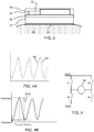
- FIG. 3 shows one possible design of a module incorporating the fan, check valve and the sensing arrangement 24.
- the module comprises a printed circuit board 34 which carries the battery 32 and sensor arrangement 24 on one side, and the fan 20 and valve 22 is mounted on the other side.
- a cover 36 is provided over the top side.
- the sensing arrangement faces outside the mask.
- Figure 4A shows schematically the rotor position (as a measured sensor voltage) against time.
- the rotational speed may be measured from the frequency of the AC component (caused by the switching events in the motor) of the DC voltage to the fan.
- This AC component originates from the current variation that the fan draws, imposed on the impedance of the power supply.
- Figure 4A shows the signal during inhalation as plot 40 and during exhalation as plot 42. There is a frequency reduction during exhalation caused by an increased load on the fan by the increased pressure gradient. The observed frequency changes thus results from the different fan performance during the breathing cycle.
- Figure 4B shows the frequency variation over time, by plotting the fan rotation speed versus time. There is a maximum difference in fan rotation speed ⁇ fan between successive maxima and minima, and this correlates with the depth of breathing. This is the first value derived from the fan rotation signal. The time between these points is used to derive the second value, for example the frequency corresponding to this time period (which is then twice the breathing rate).
- the first value maybe obtained from the raw fan rotation signal or there may be smoothing carried out first.
- the maximum swing there are at least two different two ways to calculate the maximum swing, based on untreated real-time speeds or treated speeds. In practice, there is noise or other fluctuations added on the real-time signals.
- a smoothing algorithm may be used to treat the real-time signal and calculate the first value from the smoothed signal.
- fan operation forces air out of the area between face and mask. This enhances comfort because exhalation is made easier. It can also draw additional air onto the face which lowers the temperature and relative humidity. Between inhalation and exhalation, the fan operation increases comfort because fresh air is sucked into the space between the face and the mask thereby cooling that space.
- the outlet valve is closed (either actively or passively) and the fan can be switched off to save power. This provides a mode of operation which is based on detecting the respiration cycle.
- the power to the fan can be increased by 30% for enhanced effectiveness.
- the pressure monitoring may be used to measure the flow resistance of the filter, in particular based on the pressure drop across the fan and filter. This can be done at switch on, when the mask is not on the face for a period of time. That resistance can be used as a proxy for the age of the filter.
- a fan using an electronically commutated brushless DC motor has internal sensors that measure the position of the rotor and switch the current through the coils in such a way that the rotor rotates.
- FIG. 5 shows an H-bridge circuit which functions as an inverter to generate an alternating voltage to the stator coils 50 of the motor from a DC supply VDD, GND.
- the inverter has a set of switches S1 to S4 to generate an alternating voltage across the coil 50.
- the switches are controlled by signals which depend on the rotor position, and these rotor position signals may be used to monitor the fan rotation.
- the system preferably measures both ambient temperature and humidity. These two measurements may be combined to provide a measure of a comfort level, such as a measure known as a heat index.
- Figure 6 shows a chart of relative humidity (%RH) versus temperature (degrees Celsius). Different regions are shaded differently to show different heat index values.
- the heat index is a function of the ambient temperature (T), the square of the ambient temperature, the ambient humidity level (rh) and the square of the ambient humidity level.
- T ambient temperature
- rh ambient humidity level
- the heat index gives a measure of the degree of comfort under different temperature and relative humidity conditions. For example, less than 29 is categorized as no discomfort, 29 to 34.5 is categorized as acceptable, 34.5 to 39 is categorized as some discomfort, 39 to 45 is categorized as great discomfort, 45 to 54 is categorized as dangerous and over 54 corresponds to imminent heat stroke. Thus, the higher the index value, the more discomfort is felt.
- the heat index is applicable when T>10 °C. For T ⁇ 10 °C other chilling parameters should be taken into account.
- the controller sets the initial fan speed rotation using the Table 1 below: Table 1 Heat Index ⁇ 29 29-34.5 34.5-39 39-45 >45 T>10 deg. 4000rpm 5000rpm 6000rpm 7000rpm 8000rpm T ⁇ 10 deg. 4000rpm
- the initial fan rotation speed increases with an increase of heat index. While T ⁇ 10 °C, a relatively low fan rotation is provided. The low fan rotation makes sure that user doesn't feel too cold.
- the fan rotation signals are obtained in real-time and the first value, representing the depth of breathing, and the second value, representing the depth of breathing, are continuously monitored.
- the normal breathing rate for an adult at rest is 12-18 bpm (breath per minute), and it increases when people are performing activities, e.g., running, fast walking or bicycling.
- the sampling window should contain at least 1 breathing cycle, otherwise the breathing rate cannot be acquired.
- the second value is thus a frequency based on the time between a consecutive maxima and minima in the fan rotation speed.
- the second value may be obtained from the raw fan rotation signal or there may be smoothing carried out first.
- a breathing rate may be defined as 0.5f.
- f another method is to identify the inflection points from descending (ascending) to ascending (descending).
- Each one is for a different range of breathing rates (i.e. different ranges for the second value) and each one shows how the breathing depth (i.e. the first value ⁇ fan) alters how the fan speed needs to be changed.
- the desired change to the fan speed depends on the current level of the fan speed (so it tends towards the desired value as indicated by "-"), on the breathing rate (in breaths per minute) and on the breathing depth ⁇ fan.
- n represents how many step changes in fan speed are made as between the fan speed settings 1 to 5 in the tables above.
- the heat index is used to set the initial speed as shown above.
- the breathing rates and volumes change with user's activities. For example, normal sitting with a breathing rate of 12 bpm and 0.5 L tidal volume will probably result in ⁇ 350 rpm fan speed change ( ⁇ fan) when the fan level is -5500 rpm (see above Table 2). If the activity increases, e.g., from sitting to walking (e.g., 20 bpm, 1 L volume), the ⁇ fan will be increased above 350 rpm, which requires an increased fan level.
- the heat index is used to help to determine which level the fan should be changed to.
- the mask may be for covering only the nose and mouth (as shown in Figure 1 ) or it may be a full face mask.
- the mask is for filtering ambient air.
- the mask design described above has the main air chamber formed by the filter material, through which the user breathes in air.
- An alternative mask design has the filter in series with the fan as also mentioned above.
- the fan assists the user in drawing in air through the filter, thus reducing the breathing effort for the user.
- An outlet valve enables breathed out air to be expelled and an inlet valve may be provided at the inlet.
- the invention may again be applied for detecting the pressure variations caused by breathing for controlling the inlet valve and/or the outlet valve.
- the fan in this example needs to be turned on during inhalation, to assist the user in drawing air through the series filter, but it may be turned off during exhalation when the outlet valve is open.
- the pressure information derived may again be used to control the fan to save power when the fan operation is not needed.
- the detection of whether the mask is worn or not may also be implemented.
- the invention may be applied to many different mask designs, with fan-assisted inhalation or exhalation, and with an air chamber formed by a filter membrane or with a sealed hermetic air chamber.
- the fan only for drawing air from inside the air chamber to the outside, for example when an exhaust valve is open.
- the pressure inside the mask volume may be maintained by the fan below the external atmospheric pressure so that there is a net flow of clean filtered air into the mask volume during exhalation.
- low pressure may be caused by the fan by during exhalation and by the user during inhalation (when the fan may be turned off).
- An alternative option is the use of the fan only for drawing air from the ambient surroundings to inside the air chamber.
- the fan operates to increase the pressure in the air chamber, but the maximum pressure in the air chamber in use remains below 4 cmH 2 O higher than the pressure outside the air chamber, in particular because no high pressure assisted breathing is intended.
- a low power fan may be used.
- the pressure inside the air chamber preferably remains below 2 cmH 2 O, or even below 1 cmH 2 O or even below 0.5 cmH 2 O, above the external atmospheric pressure.
- the pollution mask is thus not for use in providing a continuous positive airway pressure, and is not a mask for delivering therapy to a patient.
- the mask is preferably battery operated so the low power operation is of particular interest.
- Figure 7 shows a mask operating method
- the method comprises:
- the method optionally includes determining that the mask is not worn in step 80 and then turning off the fan, based on the first value or the first and second values.
- controller which can be implemented in numerous ways, with software and/or hardware, to perform the various functions required.
- a processor is one example of a controller which employs one or more microprocessors that maybe programmed using software (e.g., microcode) to perform the required functions.
- a controller may however be implemented with or without employing a processor, and also maybe implemented as a combination of dedicated hardware to perform some functions and a processor (e.g., one or more programmed microprocessors and associated circuitry) to perform other functions.
- controller components that may be employed in various embodiments of the present disclosure include, but are not limited to, conventional microprocessors, application specific integrated circuits (ASICs), and field-programmable gate arrays (FPGAs).
- ASICs application specific integrated circuits
- FPGAs field-programmable gate arrays
- a processor or controller may be associated with one or more storage media such as volatile and non-volatile computer memory such as RAM, PROM, EPROM, and EEPROM.
- the storage media may be encoded with one or more programs that, when executed on one or more processors and/or controllers, perform the required functions.
- Various storage media maybe fixed within a processor or controller or may be transportable, such that the one or more programs stored thereon can be loaded into a processor or controller.
Landscapes
- Health & Medical Sciences (AREA)
- Life Sciences & Earth Sciences (AREA)
- Pulmonology (AREA)
- General Health & Medical Sciences (AREA)
- Medical Informatics (AREA)
- Molecular Biology (AREA)
- Pathology (AREA)
- Engineering & Computer Science (AREA)
- Biomedical Technology (AREA)
- Heart & Thoracic Surgery (AREA)
- Physics & Mathematics (AREA)
- Biophysics (AREA)
- Surgery (AREA)
- Animal Behavior & Ethology (AREA)
- Physiology (AREA)
- Public Health (AREA)
- Veterinary Medicine (AREA)
- Business, Economics & Management (AREA)
- Emergency Management (AREA)
- Respiratory Apparatuses And Protective Means (AREA)
Priority Applications (7)
| Application Number | Priority Date | Filing Date | Title |
|---|---|---|---|
| EP19150499.2A EP3677313A1 (fr) | 2019-01-07 | 2019-01-07 | Masque de pollution et procédé de commande |
| PCT/EP2019/080709 WO2020094850A1 (fr) | 2018-11-09 | 2019-11-08 | Masque anti-pollution et procédé de commande |
| JP2021523164A JP7402870B2 (ja) | 2018-11-09 | 2019-11-08 | 汚染用マスク及びその制御方法 |
| EP19801016.7A EP3877057A1 (fr) | 2018-11-09 | 2019-11-08 | Masque anti-pollution et procédé de commande |
| CN201921922759.XU CN212214401U (zh) | 2018-11-09 | 2019-11-08 | 防污染面罩 |
| CN201980073329.1A CN113038993A (zh) | 2018-11-09 | 2019-11-08 | 防污染面罩及控制方法 |
| CN201911088591.1A CN111167039B (zh) | 2018-11-09 | 2019-11-08 | 防污染面罩及控制方法 |
Applications Claiming Priority (1)
| Application Number | Priority Date | Filing Date | Title |
|---|---|---|---|
| EP19150499.2A EP3677313A1 (fr) | 2019-01-07 | 2019-01-07 | Masque de pollution et procédé de commande |
Publications (1)
| Publication Number | Publication Date |
|---|---|
| EP3677313A1 true EP3677313A1 (fr) | 2020-07-08 |
Family
ID=65009611
Family Applications (1)
| Application Number | Title | Priority Date | Filing Date |
|---|---|---|---|
| EP19150499.2A Withdrawn EP3677313A1 (fr) | 2018-11-09 | 2019-01-07 | Masque de pollution et procédé de commande |
Country Status (1)
| Country | Link |
|---|---|
| EP (1) | EP3677313A1 (fr) |
Cited By (2)
| Publication number | Priority date | Publication date | Assignee | Title |
|---|---|---|---|---|
| CN113546341A (zh) * | 2021-07-30 | 2021-10-26 | 佛山市顺德区美的电子科技有限公司 | 口罩及其控制方法、装置以及存储介质 |
| US20250222283A1 (en) * | 2024-01-04 | 2025-07-10 | Changzhou Shine Science&Technology Co.Ltd. | Method and system for controlling pressure in mask, and respirator |
Citations (3)
| Publication number | Priority date | Publication date | Assignee | Title |
|---|---|---|---|---|
| GB2472592A (en) * | 2009-08-11 | 2011-02-16 | 3M Innovative Properties Co | A control unit for respirator |
| WO2016157159A1 (fr) * | 2015-04-03 | 2016-10-06 | Microsfere Pte. Ltd. | Masques respiratoires, systèmes et procédés |
| WO2018215225A1 (fr) * | 2017-05-22 | 2018-11-29 | Koninklijke Philips N.V. | Masque anti-pollution et procédé de commande |
-
2019
- 2019-01-07 EP EP19150499.2A patent/EP3677313A1/fr not_active Withdrawn
Patent Citations (3)
| Publication number | Priority date | Publication date | Assignee | Title |
|---|---|---|---|---|
| GB2472592A (en) * | 2009-08-11 | 2011-02-16 | 3M Innovative Properties Co | A control unit for respirator |
| WO2016157159A1 (fr) * | 2015-04-03 | 2016-10-06 | Microsfere Pte. Ltd. | Masques respiratoires, systèmes et procédés |
| WO2018215225A1 (fr) * | 2017-05-22 | 2018-11-29 | Koninklijke Philips N.V. | Masque anti-pollution et procédé de commande |
Cited By (3)
| Publication number | Priority date | Publication date | Assignee | Title |
|---|---|---|---|---|
| CN113546341A (zh) * | 2021-07-30 | 2021-10-26 | 佛山市顺德区美的电子科技有限公司 | 口罩及其控制方法、装置以及存储介质 |
| US20250222283A1 (en) * | 2024-01-04 | 2025-07-10 | Changzhou Shine Science&Technology Co.Ltd. | Method and system for controlling pressure in mask, and respirator |
| US12364881B1 (en) * | 2024-01-04 | 2025-07-22 | Changzhou Shine Science & Technology Co. Ltd. | Method and system for controlling pressure in mask, and respirator |
Similar Documents
| Publication | Publication Date | Title |
|---|---|---|
| JP7402870B2 (ja) | 汚染用マスク及びその制御方法 | |
| EP3630247B1 (fr) | Masque anti-pollution et procédé de commande | |
| EP3915645A1 (fr) | Masque de pollution et procédé de commande | |
| EP3661607B1 (fr) | Dispositif de contrôle et procédé de commande de cycle respiratoire | |
| CN114072209B (zh) | 呼吸分析遮罩及呼吸分析方法 | |
| EP3856360B1 (fr) | Masque de pollution et procédé de commande | |
| EP3441100A1 (fr) | Appareil respiratoire à base de masque et procédé de commande | |
| EP3677313A1 (fr) | Masque de pollution et procédé de commande | |
| EP3791936A1 (fr) | Masque et procédé d'analyse respiratoire | |
| WO2019043110A1 (fr) | Appareil respiratoire à masque et procédé de commande | |
| EP3677312A1 (fr) | Masque de pollution et procédé de commande | |
| EP3791934A1 (fr) | Masque de pollution pouvant détecter la pollution | |
| JP6944088B1 (ja) | 汚染用マスク及びその制御方法 | |
| WO2021004963A1 (fr) | Masque anti-pollution à détection de pollution | |
| EP3444013A1 (fr) | Dispositif de contrôle et procédé de commande de cycle respiratoire | |
| EP3669948A1 (fr) | Masque de pollution et procédé de commande | |
| EP3925531A1 (fr) | Système et procédé de surveillance de posture |
Legal Events
| Date | Code | Title | Description |
|---|---|---|---|
| PUAI | Public reference made under article 153(3) epc to a published international application that has entered the european phase |
Free format text: ORIGINAL CODE: 0009012 |
|
| STAA | Information on the status of an ep patent application or granted ep patent |
Free format text: STATUS: THE APPLICATION HAS BEEN PUBLISHED |
|
| AK | Designated contracting states |
Kind code of ref document: A1 Designated state(s): AL AT BE BG CH CY CZ DE DK EE ES FI FR GB GR HR HU IE IS IT LI LT LU LV MC MK MT NL NO PL PT RO RS SE SI SK SM TR |
|
| AX | Request for extension of the european patent |
Extension state: BA ME |
|
| STAA | Information on the status of an ep patent application or granted ep patent |
Free format text: STATUS: THE APPLICATION IS DEEMED TO BE WITHDRAWN |
|
| 18D | Application deemed to be withdrawn |
Effective date: 20210112 |