EP3677520B1 - Vorrichtung zur herstellung von schlauchbeuteln mit mehrkantsiegelung - Google Patents
Vorrichtung zur herstellung von schlauchbeuteln mit mehrkantsiegelung Download PDFInfo
- Publication number
- EP3677520B1 EP3677520B1 EP19208224.6A EP19208224A EP3677520B1 EP 3677520 B1 EP3677520 B1 EP 3677520B1 EP 19208224 A EP19208224 A EP 19208224A EP 3677520 B1 EP3677520 B1 EP 3677520B1
- Authority
- EP
- European Patent Office
- Prior art keywords
- film
- disposed
- film guide
- sealing
- forming
- Prior art date
- Legal status (The legal status is an assumption and is not a legal conclusion. Google has not performed a legal analysis and makes no representation as to the accuracy of the status listed.)
- Active
Links
Images



Classifications
-
- B—PERFORMING OPERATIONS; TRANSPORTING
- B29—WORKING OF PLASTICS; WORKING OF SUBSTANCES IN A PLASTIC STATE IN GENERAL
- B29C—SHAPING OR JOINING OF PLASTICS; SHAPING OF MATERIAL IN A PLASTIC STATE, NOT OTHERWISE PROVIDED FOR; AFTER-TREATMENT OF THE SHAPED PRODUCTS, e.g. REPAIRING
- B29C66/00—General aspects of processes or apparatus for joining preformed parts
- B29C66/40—General aspects of joining substantially flat articles, e.g. plates, sheets or web-like materials; Making flat seams in tubular or hollow articles; Joining single elements to substantially flat surfaces
- B29C66/41—Joining substantially flat articles ; Making flat seams in tubular or hollow articles
- B29C66/43—Joining a relatively small portion of the surface of said articles
- B29C66/431—Joining the articles to themselves
- B29C66/4312—Joining the articles to themselves for making flat seams in tubular or hollow articles, e.g. transversal seams
- B29C66/43121—Closing the ends of tubular or hollow single articles, e.g. closing the ends of bags
-
- B—PERFORMING OPERATIONS; TRANSPORTING
- B65—CONVEYING; PACKING; STORING; HANDLING THIN OR FILAMENTARY MATERIAL
- B65B—MACHINES, APPARATUS OR DEVICES FOR, OR METHODS OF, PACKAGING ARTICLES OR MATERIALS; UNPACKING
- B65B9/00—Enclosing successive articles, or quantities of material, e.g. liquids or semiliquids, in flat, folded, or tubular webs of flexible sheet material; Subdividing filled flexible tubes to form packages
- B65B9/10—Enclosing successive articles, or quantities of material, in preformed tubular webs, or in webs formed into tubes around filling nozzles, e.g. extruded tubular webs
- B65B9/20—Enclosing successive articles, or quantities of material, in preformed tubular webs, or in webs formed into tubes around filling nozzles, e.g. extruded tubular webs the webs being formed into tubes in situ around the filling nozzles
- B65B9/2056—Machines for packages of special type or form
-
- B—PERFORMING OPERATIONS; TRANSPORTING
- B31—MAKING ARTICLES OF PAPER, CARDBOARD OR MATERIAL WORKED IN A MANNER ANALOGOUS TO PAPER; WORKING PAPER, CARDBOARD OR MATERIAL WORKED IN A MANNER ANALOGOUS TO PAPER
- B31B—MAKING CONTAINERS OF PAPER, CARDBOARD OR MATERIAL WORKED IN A MANNER ANALOGOUS TO PAPER
- B31B70/00—Making flexible containers, e.g. envelopes or bags
- B31B70/60—Uniting opposed surfaces or edges; Taping
- B31B70/64—Uniting opposed surfaces or edges; Taping by applying heat or pressure
-
- B—PERFORMING OPERATIONS; TRANSPORTING
- B29—WORKING OF PLASTICS; WORKING OF SUBSTANCES IN A PLASTIC STATE IN GENERAL
- B29C—SHAPING OR JOINING OF PLASTICS; SHAPING OF MATERIAL IN A PLASTIC STATE, NOT OTHERWISE PROVIDED FOR; AFTER-TREATMENT OF THE SHAPED PRODUCTS, e.g. REPAIRING
- B29C65/00—Joining or sealing of preformed parts, e.g. welding of plastics materials; Apparatus therefor
- B29C65/02—Joining or sealing of preformed parts, e.g. welding of plastics materials; Apparatus therefor by heating, with or without pressure
-
- B—PERFORMING OPERATIONS; TRANSPORTING
- B29—WORKING OF PLASTICS; WORKING OF SUBSTANCES IN A PLASTIC STATE IN GENERAL
- B29C—SHAPING OR JOINING OF PLASTICS; SHAPING OF MATERIAL IN A PLASTIC STATE, NOT OTHERWISE PROVIDED FOR; AFTER-TREATMENT OF THE SHAPED PRODUCTS, e.g. REPAIRING
- B29C65/00—Joining or sealing of preformed parts, e.g. welding of plastics materials; Apparatus therefor
- B29C65/02—Joining or sealing of preformed parts, e.g. welding of plastics materials; Apparatus therefor by heating, with or without pressure
- B29C65/18—Joining or sealing of preformed parts, e.g. welding of plastics materials; Apparatus therefor by heating, with or without pressure using heated tools
-
- B—PERFORMING OPERATIONS; TRANSPORTING
- B29—WORKING OF PLASTICS; WORKING OF SUBSTANCES IN A PLASTIC STATE IN GENERAL
- B29C—SHAPING OR JOINING OF PLASTICS; SHAPING OF MATERIAL IN A PLASTIC STATE, NOT OTHERWISE PROVIDED FOR; AFTER-TREATMENT OF THE SHAPED PRODUCTS, e.g. REPAIRING
- B29C66/00—General aspects of processes or apparatus for joining preformed parts
- B29C66/80—General aspects of machine operations or constructions and parts thereof
- B29C66/84—Specific machine types or machines suitable for specific applications
- B29C66/851—Bag or container making machines
- B29C66/8511—Bag making machines
-
- B—PERFORMING OPERATIONS; TRANSPORTING
- B65—CONVEYING; PACKING; STORING; HANDLING THIN OR FILAMENTARY MATERIAL
- B65B—MACHINES, APPARATUS OR DEVICES FOR, OR METHODS OF, PACKAGING ARTICLES OR MATERIALS; UNPACKING
- B65B9/00—Enclosing successive articles, or quantities of material, e.g. liquids or semiliquids, in flat, folded, or tubular webs of flexible sheet material; Subdividing filled flexible tubes to form packages
- B65B9/10—Enclosing successive articles, or quantities of material, in preformed tubular webs, or in webs formed into tubes around filling nozzles, e.g. extruded tubular webs
- B65B9/20—Enclosing successive articles, or quantities of material, in preformed tubular webs, or in webs formed into tubes around filling nozzles, e.g. extruded tubular webs the webs being formed into tubes in situ around the filling nozzles
- B65B9/2042—Means for altering the cross-section of the tube filling opening prior to transversal sealing, e.g. tube spreading devices
-
- B—PERFORMING OPERATIONS; TRANSPORTING
- B29—WORKING OF PLASTICS; WORKING OF SUBSTANCES IN A PLASTIC STATE IN GENERAL
- B29L—INDEXING SCHEME ASSOCIATED WITH SUBCLASS B29C, RELATING TO PARTICULAR ARTICLES
- B29L2031/00—Other particular articles
- B29L2031/712—Containers; Packaging elements or accessories, Packages
- B29L2031/7128—Bags, sacks, sachets
-
- B—PERFORMING OPERATIONS; TRANSPORTING
- B65—CONVEYING; PACKING; STORING; HANDLING THIN OR FILAMENTARY MATERIAL
- B65B—MACHINES, APPARATUS OR DEVICES FOR, OR METHODS OF, PACKAGING ARTICLES OR MATERIALS; UNPACKING
- B65B2220/00—Specific aspects of the packaging operation
- B65B2220/12—Creating additional longitudinal welds on horizontal or vertical form fill seal [FFS] machines for stiffening packages or for creating package edges
Definitions
- the present invention relates to a device for the production of tubular bags with polygonal sealing with a forming shoulder for forming a flat film web into a wrapping web, a format tube surrounded by the wrapping web and a longitudinal seam forming device surrounding the format tube with a film guide device for forming film overlap areas running in the transport direction of the film web and a Heat sealing device for forming longitudinal sealing seams in the film overlap areas, the format tube having a number of fins adjacent to a forming shoulder outlet for forming the film overlapping areas in relation to the number of longitudinal sealing seams.
- a device of the type mentioned, which enables the production of tubular bags, is from the EP 0 627 355 B1 known. Further devices for the production of tubular bags with polygonal sealing are the subject of JP H10 245002 , the DE 23 37 216 , the EP 1 609 720 , the JP 2004 352306 and the JP 2005119185 . the
- the device according to the invention has the features of claim 1.
- the film guide device has first and second film guide devices assigned to the fins in such a way that one fin is arranged between a first and a second film guide device to form a double guide gap, the first and second film guide devices being arranged independently of one another in their relative arrangement to Fin are adjustable.
- the device according to the invention enables the production of overlapping areas due to the formation of the double guide gap resulting from the relative arrangement of the first and second foil guiding devices with respect to the fins, without the prior formation of a foil tube with a closed foil web cross-section being necessary. Furthermore, it is also not necessary to provide sealing tools of the heat sealing device in a defined arrangement relative to the fins in order to form the overlapping areas.
- the configuration of the device according to the invention enables the overlap areas to be produced on the still open film web cross section having wrapping web, since the formation of the overlapping areas on the film web is independent of the formation of a first longitudinal sealing seam, which only enables the formation of a film tube by connecting the film web edges through the double guide gap, which is formed by the relative arrangement of the fins with respect to the first and second film guide devices .
- the formation of the longitudinal sealing seam that connects the film web edges to one another, which produces the film tube from the wrapping web, can take place simultaneously with the further longitudinal sealing seams for forming the polygonal seal.
- the device according to the invention enables easy adaptation of the film guide device to the respective film web used for the production of the tubular bag due to the independently adjustable first and second film guide devices in their relative arrangement relative to the fins Flexibility and the film thickness can be taken into account.
- the adjustability of the film guiding device makes it possible, in particular, to make adjustments to the film guiding device in situ, that is to say without first having to dismantle the format tube and the film guiding device from a system for producing tubular bags.
- no post-processing of the film guiding device for example by removing material from components of the film guiding device, that is to say for example the first and second film guiding devices, is required in order to influence the gap dimensions necessary to form the overlapping areas.
- the first film guide devices are arranged on a format tube carrier
- the first film guide devices are preferably arranged on an arm that is adjustably arranged at least in one axial direction on the format tube carrier, so that the format tube carrier, which is used to install the format tube, can be used at the same time for mounting the first film guide devices.
- first film guide devices are arranged on the boom so that they can be adjusted in at least one axial direction
- a first adjustment mechanism can be formed on the boom so that in a particularly simple embodiment of the device, the format tube carrier used as standard can still be used in combination with the device according to the invention.
- the second film guide devices are arranged on the longitudinal seam formation device connected to the format tube carrier, the second film guide devices each being arranged on a sealing bar of the longitudinal seam formation device, so that a component that is required in any case to form the longitudinal seam formation device for installing the second film guide devices is also required in cooperation with a heat sealing device enables the production of the longitudinal seams, can be used.
- a second adjustment axis for particularly precise positioning of the second film guide devices is defined in a simple manner.
- two sealing strips are preferably arranged adjustable in their relative arrangement on a sealing strip support, the sealing strip support being adjustably arranged on the longitudinal seam formation device.
- sealing bars are adjustable on a first axis in a plane perpendicular to the transport direction of the film web and the sealing bar carrier is adjustable on a second axis perpendicular to the first axis, particularly precise positioning of the second film guide devices is also possible.
- the device 10 shown comprises a format tube 12 arranged on a format tube carrier 11, which is surrounded on an upper forming shoulder section 13 by a forming shoulder 14 in such a way that an annular gap 15 is formed between the forming shoulder section 13 and the forming shoulder 14, into which one in Fig. 1
- the only indicated film web 16 fed to the forming shoulder 14 is introduced in contact with a forming shoulder surface 50 such that the film edges 18, 19 at guide edges 23, 24 of the forming shoulder 14 that are converging to one another are moved towards one another and in adjacent ones Relative arrangement below a forming shoulder outlet 20 formed at the end of the guide edges 18, 19 reach a film guide device 21, the function of which is explained in more detail below.
- the film guide device 21 is located in a common film guide plane F with fins 22, which in the present case are formed on the format tube 12 in such a way that, in particular Fig. 3 shows, in each case two fins 22 arranged opposite one another on the circumference of the format tube 12 are located in a common fin plane FI 1 and FI 2 , in the present case the two fin planes FI 1 and FI 2 are arranged parallel to one another and are each at the same distance from one another opposite sides of a central axis M of the format tube 12 are located.
- the fins 22 are each in the transport direction T ( Fig. 1 ) of the film web is formed with a rising guide edge 23 which, in the further course of the fins 22 in the transport direction T, merges into a guide edge 24 configured parallel to the surface of the format tube 12.
- a first foil guide device 25 and a second foil guide device 26 extend on both sides of the fins 22 and along them, in such a way that, due to the relative arrangement of the first and second foil guide devices 25, 26 with the fin 22 arranged in between, a double guide gap 27 is formed with a first guide gap 28 which is formed between the first film guide device 25 and the fin 22, and a second guide gap 29 which is formed between the fin 22 and the second film guide device 26.
- the first film guide devices 25 are located on the format tube carrier 11 ( Fig. 2 ), and the second film guide devices 26 are each on a sealing bar 30 a longitudinal seam forming device 31, each in combination with a sealing jaw 32 ( Fig. 3 ) a heat sealing device 33 are used to form longitudinal sealing seams.
- the sealing jaws 32 of the heat-sealing device 33 are shown only schematically, with one sealing jaw 32 being arranged opposite a sealing bar 30 of the longitudinal seam-forming device 31.
- the first foil guide devices 25 and the second foil guide devices 26 can be changed independently of one another in their relative arrangement with respect to the fin 22 arranged between a first foil guide device 25 and a second foil guide device 26 and fixed in the changed relative arrangement.
- the first film guide devices 25 can each be adjusted in a first axial direction X 1 on an arm 34 via an adjusting device 35, which is designed here as an elongated screw connection.
- the arms 34 are in their relative arrangement with respect to the format tube carrier 11, which for reasons of clarity in Fig. 4 is shown only incompletely, also adjustable in a second axial direction X 2 , an adjusting device 36 being used for this, which is also designed as an elongated screw connection.
- an actuation of the adjusting device 35 enables a change in the relative position of the first film guide device 25 for setting the distance a 1 with respect to the fin 22 ( Fig. 5 ), whereby actuation of the actuating device 36 enables the distance a 2 between the first film guide device 25 and the format tube 12 to be changed.
- the second film guide devices 26, which are each arranged on a sealing bar 30 of the longitudinal seam formation device 31, can on the one hand, via an adjusting device 37, which in the present case is also designed as an elongated screw connection, can be changed in its position relative to the sealing strip 30 along an axis direction X 3 , so that the distance a 3 of the second film guide device 26 relative to the format tube 12 can be influenced by this.
- the sealing strips 30 can be positioned along an axis direction X 4 ( Fig. 4 ) are each changed in their distance from a sealing bar carrier 38.
- an adjusting device 39 is provided between a sealing bar 30 and a sealing bar carrier 38, which in the present case is formed from a bolted connection, the length of which between the sealing bar 30 and the sealing bar carrier 38 can be changed.
- the coupling of two adjacent sealing strips 30 by means of a common sealing strip carrier 38 enables a common adjustment of the second film guide devices 26 along the axis direction X 5 by a corresponding change in the relative arrangement of the axial sealing strip carrier ends 40 in a longitudinal guide 41 formed on the molded tube carrier 11.
- FIG. 3 shows a cross-section through the film guiding device, enables the film guiding device 21 in cooperation with the fins 22 formed on the circumference of the format tube 12 that in a wrapping web 51 exiting from the forming shoulder outlet 20, which when exiting the forming shoulder outlet 20 and entering the Film guide device 21 is not yet formed into a film tube with a closed cross-section and does not yet have a longitudinal seam as a prerequisite for forming the film tube, when the wrapping web 21 enters the film guide device 21 in the area of three guide arrangements 42, 43, 44 of the total of four each have a first film guide device 25 and a second film guide device 26 having guide arrangements 42 to 45 continuous film overlap regions 46 are formed, wherein in the a film overlap region 47 is formed below the guide edges 18, 19 on the forming shoulder outlet 20, in which the film edges 18, 19 are parallel to one another and are not yet connected to one another.
- the heat sealing device 32 with the sealing jaws 33 opposite a sealing bar 30 is located in the transport direction of the film web below the film guiding device 21, so that the formation of a total of four longitudinal sealing seams in the film overlapping areas 46, 47 only takes place after the wrapping web 51 exits the film guiding device 21,
- the longitudinal sealing seam for connecting the film edges 18, 19 opposite one another in the film overlap area 47 which first enables the formation of a film tube, also takes place simultaneously with the formation of the further three longitudinal sealing seams in the film overlap areas 46 for producing the polygonal seal.
Landscapes
- Engineering & Computer Science (AREA)
- Mechanical Engineering (AREA)
- Containers And Plastic Fillers For Packaging (AREA)
- Making Paper Articles (AREA)
Description
- Die vorliegende Erfindung betrifft eine Vorrichtung zur Herstellung von Schlauchbeuteln mit Mehrkantsiegelung mit einer Formschulter zum Umformen einer ebenen Folienbahn zu einer Hüllbahn, einem von der Hüllbahn umgebenen Formatrohr und einer das Formatrohr umgebenden Längsnahtbildungseinrichtung mit einer Folienführungseinrichtung zur Ausbildung von in Transportrichtung der Folienbahn verlaufenden Folienüberlappungsbereichen und einer Heißsiegeleinrichtung zur Ausbildung von Längssiegelnähten in den Folienüberlappungsbereichen, wobei das Formatrohr benachbart einem Formschulterauslauf zur Ausbildung der Folienüberlappungsbereiche eine in der Anzahl der Anzahl der Längssiegelnähte entsprechende Anzahl von Finnen aufweist.
- Eine Vorrichtung der eingangs genannten Art, die die Herstellung von Schlauchbeuteln ermöglicht, ist aus der
EP 0 627 355 B1 bekannt. Weitere Vorrichtungen zur Herstellung von Schlauchbeuteln mit Mehrkantsiegelung sind Gegenstand derJP H10 245002 DE 23 37 216 , derEP 1 609 720 , derJP 2004 352306 JP 2005119185 - Herstellung der Längssiegelnähte mittels der bekannten Vorrichtung setzt voraus, dass aus der bis zum Einlauf in die Formschulter noch ebenen Folienbahn nach Umformung zu einem das Formatrohr einhüllenden Hüllschlauch durch Herstellung einer ersten Längssiegelnaht bereits ein Folienschlauch gebildet ist, um dann anschließend mittels der am Formatrohr ausgebildeten Finnen in Kombination mit einer jeweils jeder Finne zugeordneten Siegelwerkzeugpaarung, die zwei gegeneinander wirkende Siegelbacken aufweist, weitere Längssiegelnähte zur Ausbildung der Mehrkantsiegelung herzustellen.
- Ausgehend von dem vorgenannten Stand der Technik ist es Aufgabe der Erfindung, eine Vorrichtung vorzuschlagen, die die Herstellung von Schlauchbeuteln mit Mehrkantsiegelung ermöglicht, die eine gleichzeitige Herstellung sämtlicher am Schlauchbeutel ausgebildeter Längssiegelnähte ermöglicht.
- Zur Lösung dieser Aufgabe weist die erfindungsgemäße Vorrichtung die Merkmale des Anspruchs 1 auf.
- Bei der erfindungsgemäßen Vorrichtung weist die Folienführungseinrichtung jeweils den Finnen zugeordnete erste und zweite Folienleiteinrichtungen auf, derart, dass jeweils eine Finne zur Ausbildung eines Doppelführungsspaltes zwischen einer ersten und einer zweiten Folienleiteinrichtung angeordnet ist, wobei die erste und die zweite Folienleiteinrichtung unabhängig voneinander in ihrer Relativanordnung zur Finne einstellbar sind.
- Im Gegensatz zu der bekannten Vorrichtung ermöglicht die erfindungsgemäße Vorrichtung aufgrund der durch die Relativanordnung der ersten und zweiten Folienleiteinrichtungen gegenüber den Finnen erfolgenden Ausbildung des Doppelführungsspalt die Herstellung von Überlappungsbereichen, ohne dass hierzu die vorhergehende Ausbildung eines Folienschlauchs mit geschlossenem Folienbahnquerschnitt erforderlich wäre. Weiterhin ist es ebenso wenig erforderlich, zur Ausbildung der Überlappungsbereiche Siegelwerkzeuge der Heißsiegeleinrichtung in einer definierten Relativanordnung zu den Finnen vorzusehen. Vielmehr ermöglicht die erfindungsgemäße Ausgestaltung der Vorrichtung eine Herstellung der Überlappungsbereiche an der noch einen offenen Folienbahnquerschnitt aufweisenden Hüllbahn, da durch den Doppelführungsspalt, der durch die Relativanordnung der Finnen gegenüber den ersten und zweiten Folienleiteinrichtungen gebildet ist, die Ausbildung der Überlappungsbereiche an der Folienbahn unabhängig von der Ausbildung einer ersten Längssiegelnaht ist, die durch Verbindung der Folienbahnränder erst die Ausbildung eines Folienschlauchs ermöglicht.
- Vorzugsweise kann vielmehr bei einem Einsatz der erfindungsgemäßen Vorrichtung die Ausbildung der die Folienbahnränder miteinander verbinden Längssiegelnaht, die aus der Hüllbahn den Folienschlauch erzeugt, gleichzeitig mit den weiteren Längssiegelnähten zur Ausbildung der Mehrkantsiegelung erfolgen.
- Darüber hinaus ermöglicht die erfindungsgemäße Vorrichtung aufgrund der unabhängig voneinander in ihrer Relativanordnung gegenüber den Finnen verstellbaren ersten und zweiten Folienleiteinrichtungen eine leichte Anpassung der Folienführungseinrichtung an die jeweilige, zur Herstellung der Schlauchbeutel verwendete Folienbahn, wobei durch eine geeignete Einstellung der Spaltweiten des Doppelführungsspaltes in besonderer Weise die Flexibilität und die Folienstärke berücksichtigt werden kann.
- Die Einstellbarkeit der Folienführungseinrichtung ermöglicht es insbesondere, Justierungen der Folienführungseinrichtung in situ vorzunehmen, also ohne das Formatrohr und die Folienführungseinrichtung zuvor aus einer Anlage zur Herstellung von Schlauchbeuteln demontieren zu müssen. Insbesondere ist keine Nachbearbeitung der Folienführungseinrichtung, etwa durch einen Materialabtrag an Komponenten der Folienführungseinrichtung, also etwa den ersten und zweiten Folienleiteinrichtungen, zur Beeinflussung der zur Ausbildung der Überlappungsbereiche notwendigen Spaltmaße erforderlich.
- Besonders vorteilhaft ist es, wenn die ersten Folienleiteinrichtungen an einem Formatrohrträger angeordnet sind, wobei die ersten Folienleiteinrichtungen vorzugsweise an einem zumindest in einer Achsenrichtung am Formatrohrträger verstellbar angeordneten Ausleger angeordnet sind, sodass der Formatrohrträger, der zur Installation des Formatrohrs dient, gleichzeitig zur Montage der ersten Folienleiteinrichtungen verwendbar ist.
- Wenn die ersten Folienleiteinrichtungen in zumindest einer Achsenrichtung am Ausleger verstellbar angeordnet sind, kann ein erster Einstellungsmechanismus am Ausleger ausgebildet sein, sodass in einer besonders einfachen Ausführungsform der Vorrichtung der standardmäßig eingesetzte Formatrohrträger unverändert auch bei einer Kombination mit der erfindungsgemäßen Vorrichtung verwendbar ist.
- Besonders vorteilhaft ist es, wenn die zweiten Folienleiteinrichtungen an der mit dem Formatrohrträger verbundenen Längsnahtbildungseinrichtung angeordnet sind, wobei die zweiten Folienleiteinrichtungen jeweils an einer Siegelleiste der Längsnahtbildungseinrichtung angeordnet sind, so dass auch zur Installation der zweiten Folienleiteinrichtungen eine ohnehin zur Ausbildung der Längsnahtbildungseinrichtung benötigte Komponente, die im Zusammenwirken mit einer Heißsiegeleinrichtung die Herstellung der Längsnähte ermöglicht, verwendet werden kann.
- Wenn zur Verstellung der zweiten Folienleiteinrichtungen die Siegelleisten der Längsnahtbildungseinrichtung verstellbar an der Längsnahtbildungseinrichtung angeordnet sind, ist auf einfache Art und Weise eine zweite Einstellachse zur besonders genauen Positionierung der zweiten Folienleiteinrichtungen definiert.
- Vorzugsweise sind zur Verstellung der Siegelleisten jeweils zwei Siegelleisten in ihrer Relativanordnung einstellbar an einem Siegelleistenträger angeordnet, wobei der Siegelleistenträger an der Längsnahtbildungseinrichtung verstellbar angeordnet ist.
- Wenn die Siegelleisten auf einer ersten Achse in einer zur Transportrichtung der Folienbahn senkrechten Stellebene und der Siegelleistenträger auf einer zweiten zur ersten Achse senkrechten Achse verstellbar angeordnet sind, ist ebenfalls eine besonders exakte Positionierung der zweiten Folienleiteinrichtungen möglich.
- Nachfolgend wird eine bevorzugte Ausführungsform der Erfindung anhand der Zeichnung näher erläutert.
- Es zeigen:
- Fig. 1
- eine isometrische Darstellung einer Vorrichtung zur Herstellung von Schlauchbeuteln mit Mehrkantsiegelung in isometrischer Darstellung;
- Fig. 2
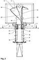
- die in
Fig. 1 gezeigte Vorrichtung in Frontansicht; - Fig. 3
- eine Schnittdarstellung der in
Fig. 2 gezeigten Vorrichtung längs Schnittlinienverlauf III - III inFig. 2 ; - Fig. 4
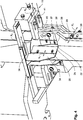
- eine vergrößerte Teilansicht der in
Fig. 1 dargestellten Vorrichtung zur Darstellung eines zwischen einer Formschulter und einem Formatrohr gebildeten Übergangsbereichs; - Fig. 5
- eine vergrößerte Teilansicht einer Führungsanordnung einer Folienführungseinrichtung.
- Die in den
Fig. 1 und2 dargestellte Vorrichtung 10 umfasst ein an einem Formatrohrträger 11 angeordnetes Formatrohr 12, das an einem oberen Formschulterabschnitt 13 von einer Formschulter 14 derart umgeben ist, dass zwischen dem Formschulterabschnitt 13 und der Formschulter 14 ein Ringspalt 15 ausgebildet ist, in den eine inFig. 1 lediglich angedeutete, auf die Formschulter 14 zugeführte Folienbahn 16 in Kontakt mit einer Formschulteroberfläche 50 derart eingeführt wird, dass Folienränder 18, 19 an konvergierend zueinander angeordneten Führungsrändern 23, 24 der Formschulter 14 aufeinander zubewegt werden und in benachbarter Relativanordnung unterhalb eines am Ende der Führungsränder 18, 19 gebildeten Formschulterauslaufs 20 zu einer Folienführungseinrichtung 21 gelangen, deren Funktion im Nachfolgenden näher erläutert wird. - Wie
Fig. 2 zeigt, befindet sich die Folienführungseinrichtung 21 in einer gemeinsamen Folienführungsebene F mit Finnen 22, die im vorliegenden Fall derart am Formatrohr 12 ausgebildet sind, dass, wie insbesondereFig. 3 zeigt, jeweils zwei einander gegenüberliegend am Umfang des Formatrohrs 12 angeordnete Finnen 22 sich in einer gemeinsamen Finnenebene FI1 und FI2 befinden, wobei im vorliegenden Fall die beiden Finnenebenen FI1 und FI2 parallel zueinander angeordnet sind und sich jeweils mit übereinstimmendem Abstand auf einander gegenüberliegenden Seiten einer Mittelachse M des Formatrohrs 12 befinden. - Wie
Fig. 2 zeigt, sind die Finnen 22 jeweils in Transportrichtung T (Fig. 1 ) der Folienbahn mit einem ansteigenden Führungsrand 23 ausgebildet, der im weiteren Verlauf der Finnen 22 in Transportrichtung T in einen parallel zur Oberfläche des Formatrohrs 12 ausgebildeten Führungsrand 24 übergeht. - Wie
Fig. 5 zeigt, erstrecken sich zu beiden Seiten der Finnen 22 und längs diesen jeweils eine erste Folienleiteinrichtung 25 und eine zweite Folienleiteinrichtung 26, derart, dass aufgrund der Relativanordnung der ersten und zweiten Folienleiteinrichtung 25, 26 mit der zwischenliegend angeordneten Finne 22 ein Doppelführungsspalt 27 ausgebildet ist mit einem ersten Führungsspalt 28, der zwischen der ersten Folienleiteinrichtung 25 und der Finne 22 ausgebildet ist, und einem zweiten Führungsspalt 29, der zwischen der Finne 22 und der zweiten Folienleiteinrichtung 26 ausgebildet ist. - Im Fall des dargestellten Ausführungsbeispiels befinden sich die ersten Folienleiteinrichtungen 25 am Formatrohrträger 11 (
Fig. 2 ), und die zweiten Folienleiteinrichtungen 26 sind jeweils an einer Siegelleiste 30 einer Längsnahtbildungseinrichtung 31 angeordnet, die jeweils in Kombination mit einer Siegelbacke 32 (Fig. 3 ) einer Heißsiegeleinrichtung 33 zur Ausbildung von Längssiegelnähten dienen. - Zum Zwecke einer möglichst übersichtlichen Darstellung sind in den
Fig. 2 und3 die Siegelbacken 32 der Heißsiegeleinrichtung 33 lediglich schematisch dargestellt, wobei jeweils eine Siegelbacke 32 gegenüberliegend einer Siegelleiste 30 der Längsnahtbildungseinrichtung 31 angeordnet ist. - Wie insbesondere anhand einer Zusammenschau der
Fig. 3 und4 deutlich wird, können die ersten Folienleiteinrichtungen 25 und die zweiten Folienleiteinrichtungen 26 unabhängig voneinander in ihrer Relativanordnung gegenüber der jeweils zwischen einer ersten Folienleiteinrichtung 25 und einer zweiten Folienleiteinrichtung 26 angeordneten Finne 22 verändert und in der veränderten Relativanordnung fixiert werden. Hierzu sind die ersten Folienleiteinrichtungen 25 jeweils an einem Ausleger 34 über eine hier als Langlochverschraubung ausgebildete Stelleinrichtung 35 in einer ersten Achsenrichtung X1 verstellbar. Darüber hinaus sind die Ausleger 34 in ihrer Relativanordnung gegenüber dem Formatrohrträger 11, der aus Gründen der Übersichtlichkeit inFig. 4 nur unvollständig dargestellt ist, in einer zweiten Achsenrichtung X2 ebenfalls verstellbar, wobei hierzu eine Stelleinrichtung 36 verwendet wird, die ebenfalls als eine Langlochverschraubung ausgebildet ist. - Wie insbesondere anhand von
Fig. 4 nachvollziehbar ist, ermöglicht eine Betätigung der Stelleinrichtung 35 eine Veränderung der Relativposition der ersten Folienleiteinrichtung 25 zur Einstellung des Abstands a1 gegenüber der Finne 22 (Fig. 5 ), wobei eine Betätigung der Stelleinrichtung 36 eine Änderung des Abstands a2 zwischen der ersten Folienleiteinrichtung 25 und dem Formatrohr 12 ermöglicht. - Die zweiten Folienleiteinrichtungen 26, welche jeweils an einer Siegelleiste 30 der Längsnahtbildungseinrichtung 31 angeordnet sind, können zum einen über eine Stelleinrichtung 37, die im vorliegenden Fall ebenfalls als Langlochverschraubung ausgebildet ist, längs einer Achsenrichtung X3 in ihrer Position gegenüber der Siegelleiste 30 verändert werden, sodass sich hierüber der Abstand a3 der zweiten Folienleiteinrichtung 26 gegenüber dem Formatrohr 12 beeinflussen lässt. Zur Änderung des Abstandes a4 der Folienleiteinrichtung 26 gegenüber der Finne 22 können die Siegelleisten 30 längs einer Achsenrichtung X4 (
Fig. 4 ) jeweils in ihrem Abstand gegenüber einem Siegelleistenträger 38 verändert werden. Hierzu ist jeweils zwischen einer Siegelleiste 30 und einem Siegelleistenträger 38 eine Stelleinrichtung 39 vorgesehen, die im vorliegenden Fall aus einer Bolzenverschraubung gebildet ist, deren Länge zwischen der Siegelleiste 30 und dem Siegelleistenträger 38 veränderbar ist. - Darüber hinaus ermöglicht die Kopplung von jeweils zwei benachbarten Siegelleisten 30 mittels eines gemeinsamen Siegelleistenträgers 38 eine gemeinsame Verstellung der zweiten Folienleiteinrichtungen 26 längs der Achsenrichtung X5 durch eine entsprechende Änderung der Relativanordnung der axialen Siegelleistenträgerenden 40 in einer am Formrohrträger 11 ausgebildeten Längsführung 41.
- Wie aus
Fig. 3 deutlich wird, die einen Querschnitt durch die Folienführungseinrichtung zeigt, ermöglicht die Folienführungseinrichtung 21 im Zusammenwirken mit den am Umfang des Formatrohrs 12 ausgebildeten Finnen 22, dass in einer aus dem Formschulterauslauf 20 austretenden Hüllbahn 51, die bei Austritt aus dem Formschulterauslauf 20 und Eintritt in die Folienführungseinrichtung 21 noch nicht zu einem Folienschlauch mit geschlossenem Querschnitt ausgebildet ist und noch keine Längsnaht als Voraussetzung zur Ausbildung des Folienschlauchs aufweist, bei Eintritt der Hüllbahn 21 in die Folienführungseinrichtung 21 im Bereich von drei Führungsanordnungen 42, 43, 44 der insgesamt vier jeweils eine erste Folienleiteinrichtung 25 und eine zweite Folienleiteinrichtung 26 aufweisenden Führungsanordnungen 42 bis 45 kontinuierliche Folienüberlappungsbereiche 46 ausgebildet werden, wobei in der unterhalb der Führungsränder 18, 19 am Formschulterauslauf 20 angeordneten Führungsanordnung 45 eine Folienüberlappungsbereich 47 ausgebildet wird, in dem die Folienränder 18, 19 parallel einander gegenüberliegen und noch nicht miteinander verbunden sind. - Wie
Fig. 2 zeigt, befindet sich die Heißsiegeleinrichtung 32 mit den jeweils einer Siegelleiste 30 gegenüberliegenden Siegelbacken 33 in Transportrichtung der Folienbahn unterhalb der Folienführungseinrichtung 21, sodass die Ausbildung von insgesamt vier Längssiegelnähten in den Folienüberlappungsbereichen 46, 47 erst nach Austritt der Hüllbahn 51 aus der Folienführungseinrichtung 21 erfolgt, wobei auch die Längssiegelnaht zur Verbindung der im Folienüberlappungsbereich 47 einander gegenüberliegenden Folienränder 18, 19, die erst die Ausbildung eines Folienschlauchs ermöglicht, gleichzeitig mit Ausbildung der weiteren drei Längssiegelnähte in den Folienüberlappungsbereichen 46 zur Herstellung der Mehrkantsiegelung erfolgt.
Claims (7)
- Vorrichtung zur Herstellung von Schlauchbeuteln mit Mehrkantsiegelung mit einer Formschulter (14) zum Umformen einer ebenen Folienbahn (16) zu einer Hüllbahn (51), einem von der Hüllbahn (51) umgebenen Formatrohr (12) und einer das Formatrohr umgebenden Längsnahtbildungseinrichtung (31) mit einer Folienführungseinrichtung (21) zur Ausbildung von in Transportrichtung der Folienbahn verlaufenden Folienüberlappungsbereichen (46, 47) und einer Heißsiegeleinrichtung (33) zur Ausbildung von Längssiegelnähten in den Folienüberlappungsbereichen (46, 47), wobei das Formatrohr (12) benachbart einem Formschulterauslauf (20) zur Ausbildung der Folienüberlappungsbereiche (46, 47) eine der Anzahl der Längssiegelnähte entsprechende Anzahl von Finnen (22) aufweist und die Folienführungseinrichtung (21) jeweils den Finnen (22) zugeordnete erste und zweite Folienleiteinrichtungen (25, 26) aufweist, derart, dass jeweils eine Finne (22) zur Ausbildung eines Doppelführungsspaltes (27) zwischen einer ersten und einer zweiten Folienleiteinrichtung (25, 26) angeordnet ist, gekennzeichnet dadurch, dass die erste und die zweite Folienleiteinrichtung (25, 26) unabhängig voneinander in ihrer Relativanordnung zur Finne (22) einstellbar sind.
- Vorrichtung nach Anspruch 1,
dadurch gekennzeichnet,
dass die ersten Folienleiteinrichtungen (25) an einem Formatrohrträger (11) angeordnet sind, wobei die ersten Folienleiteinrichtungen (25) an einem zumindest in eine Achsenrichtung am Formschulterträger (11) verstellbar angeordneten Ausleger (34) angeordnet sind. - Vorrichtung nach Anspruch 2,
dadurch gekennzeichnet,
dass die ersten Folienleiteinrichtungen (25) in zumindest einer Achsenrichtung am Ausleger (34) verstellbar angeordnet sind. - Vorrichtung nach einem der vorangehenden Ansprüche,
dadurch gekennzeichnet,
dass die zweiten Folienleiteinrichtungen (26) an der mit dem Formatrohrträger (11) verbundenen Längsnahtbildungseinrichtung (31) angeordnet sind, wobei die zweiten Folienleiteinrichtungen (26) jeweils an einer Siegelleiste (30) der Längsnahtbildungseinrichtung (31) angeordnet sind. - Vorrichtung nach Anspruch 4,
dadurch gekennzeichnet,
dass zur Verstellung der zweiten Folienleiteinrichtungen (26) die Siegelleisten (30) der Längsnahtbildungseinrichtung (31) verstellbar an der Längsnahtbildungseinrichtung (31) angeordnet sind. - Vorrichtung nach Anspruch 5,
dadurch gekennzeichnet,
dass zur Verstellung der Siegelleisten (30) jeweils zwei Siegelleisten (30) in ihrer Relativanordnung einstellbar an einem Siegelleistenträger (38) angeordnet sind, wobei der Siegelleistenträger (38) an der Längsnahtbildungseinrichtung (31) verstellbar angeordnet ist. - Vorrichtung nach Anspruch 6,
dadurch gekennzeichnet,
dass die Siegelleisten (30) auf einer ersten Achse in einer zur Transportrichtung der Folienbahn (16) senkrechten Stellebene und der Siegelleistenträger (38) auf einer zweiten zur ersten Achse senkrechten Achse verstellbar angeordnet sind.
Priority Applications (1)
| Application Number | Priority Date | Filing Date | Title |
|---|---|---|---|
| PL19208224T PL3677520T3 (pl) | 2018-11-26 | 2019-11-11 | Urządzenie do wytwarzania toreb rurowych z wielokrawędziowym zgrzewem |
Applications Claiming Priority (1)
| Application Number | Priority Date | Filing Date | Title |
|---|---|---|---|
| DE102018129676.2A DE102018129676A1 (de) | 2018-11-26 | 2018-11-26 | Vorrichtung zur Herstellung von Schlauchbeuteln mit Mehrkantsiegelung |
Publications (3)
| Publication Number | Publication Date |
|---|---|
| EP3677520A1 EP3677520A1 (de) | 2020-07-08 |
| EP3677520B1 true EP3677520B1 (de) | 2022-01-05 |
| EP3677520B8 EP3677520B8 (de) | 2022-04-20 |
Family
ID=68531392
Family Applications (1)
| Application Number | Title | Priority Date | Filing Date |
|---|---|---|---|
| EP19208224.6A Active EP3677520B8 (de) | 2018-11-26 | 2019-11-11 | Vorrichtung zur herstellung von schlauchbeuteln mit mehrkantsiegelung |
Country Status (7)
| Country | Link |
|---|---|
| US (1) | US11225032B2 (de) |
| EP (1) | EP3677520B8 (de) |
| CN (1) | CN111216414B (de) |
| DE (1) | DE102018129676A1 (de) |
| ES (1) | ES2910325T3 (de) |
| PL (1) | PL3677520T3 (de) |
| RU (1) | RU2735365C1 (de) |
Families Citing this family (1)
| Publication number | Priority date | Publication date | Assignee | Title |
|---|---|---|---|---|
| DE102023114576A1 (de) | 2023-06-02 | 2024-12-05 | Baumann Maschinenbau Solms Gmbh & Co.Kg | Einrichtung einer Schlauchbeutelmaschine |
Citations (2)
| Publication number | Priority date | Publication date | Assignee | Title |
|---|---|---|---|---|
| JP2004352306A (ja) * | 2003-05-29 | 2004-12-16 | Tokyo Autom Mach Works Ltd | ヘム付き製袋装置 |
| JP2005119185A (ja) * | 2003-10-17 | 2005-05-12 | Tokyo Autom Mach Works Ltd | 筋目付け機構を備えた製袋装置 |
Family Cites Families (13)
| Publication number | Priority date | Publication date | Assignee | Title |
|---|---|---|---|---|
| DE2337216A1 (de) * | 1973-07-21 | 1975-02-06 | Mira Pak Inc | Verfahren zur herstellung von beutelpackungen und vorrichtung zur durchfuehrung des verfahrens |
| DE4203798C2 (de) | 1992-02-10 | 1999-07-15 | Rovema Gmbh | Verfahren und Vorrichtung zur Herstellung eines Schlauchbeutels |
| US5746043A (en) * | 1992-06-29 | 1998-05-05 | Pacmac, Inc. | Convertible form, fill and seal packaging machine and method |
| JP3463909B2 (ja) * | 1997-03-05 | 2003-11-05 | 茨木精機株式会社 | 製筒装置 |
| CN1165458C (zh) * | 1999-11-22 | 2004-09-08 | 织宽工程株式会社 | 用于自立袋的成形、充填和密封设备 |
| DE10027581B4 (de) * | 2000-06-02 | 2004-07-08 | Hastamat Verpackungstechnik Gmbh & Co. Kg | Schlauchbeutelmaschine zur Herstellung von Beuteln mit Kantensiegelung |
| DE10149476A1 (de) * | 2001-10-08 | 2003-04-17 | Rovema Gmbh | Schlauchbeutelmaschine zum Herstellen kantenverschweißter Schlauchbeutel |
| ITBO20020463A1 (it) * | 2002-07-18 | 2004-01-19 | Awax Progettazione | Apparato per la termosaldatura continua ed a tenuta dei lembi longitudinali e sovrapposti di elementi tubolari di film termoplastico di spes |
| ITMI20040312U1 (it) * | 2004-06-24 | 2004-09-24 | Ilapak Res & Developments Sa | Macchina imbustatrice per la formazione di buste con bordi laterali di sagomatura |
| EP1894845A1 (de) * | 2006-09-04 | 2008-03-05 | CFS Weert B.V. | Verfahren zum Herstellen von Doypack-Beuteln |
| JPWO2008053847A1 (ja) * | 2006-10-30 | 2010-02-25 | 株式会社イシダ | 製袋包装機 |
| CN103895891B (zh) * | 2012-12-26 | 2016-01-06 | 株式会社吴羽 | 筒状体制造装置 |
| DE102013210630B4 (de) * | 2013-06-07 | 2015-09-03 | Hastamat Verpackungstechnik Gmbh | Folienbahnumlenkvorrichtung sowie Vorrichtung zur Herstellung von Verpackungseinheiten umfassend eine Folienbahnumlenkvorrichtung |
-
2018
- 2018-11-26 DE DE102018129676.2A patent/DE102018129676A1/de not_active Ceased
-
2019
- 2019-11-11 EP EP19208224.6A patent/EP3677520B8/de active Active
- 2019-11-11 PL PL19208224T patent/PL3677520T3/pl unknown
- 2019-11-11 ES ES19208224T patent/ES2910325T3/es active Active
- 2019-11-22 RU RU2019137682A patent/RU2735365C1/ru active
- 2019-11-25 US US16/693,620 patent/US11225032B2/en active Active
- 2019-11-26 CN CN201911172173.0A patent/CN111216414B/zh active Active
Patent Citations (2)
| Publication number | Priority date | Publication date | Assignee | Title |
|---|---|---|---|---|
| JP2004352306A (ja) * | 2003-05-29 | 2004-12-16 | Tokyo Autom Mach Works Ltd | ヘム付き製袋装置 |
| JP2005119185A (ja) * | 2003-10-17 | 2005-05-12 | Tokyo Autom Mach Works Ltd | 筋目付け機構を備えた製袋装置 |
Also Published As
| Publication number | Publication date |
|---|---|
| DE102018129676A1 (de) | 2020-05-28 |
| ES2910325T3 (es) | 2022-05-12 |
| RU2735365C1 (ru) | 2020-10-30 |
| EP3677520A1 (de) | 2020-07-08 |
| PL3677520T3 (pl) | 2022-05-02 |
| US11225032B2 (en) | 2022-01-18 |
| CN111216414B (zh) | 2023-12-15 |
| CN111216414A (zh) | 2020-06-02 |
| US20200164600A1 (en) | 2020-05-28 |
| EP3677520B8 (de) | 2022-04-20 |
Similar Documents
| Publication | Publication Date | Title |
|---|---|---|
| DE102012211350A1 (de) | Flachrohr und Wärmeübertrager mit einem solchen Flachrohr | |
| EP0473036B1 (de) | Drahtbiegemaschine für mit Isolierung versehenen Draht | |
| EP0944444B1 (de) | Einrichtung zum formen eines spiralrohres | |
| EP3677520B1 (de) | Vorrichtung zur herstellung von schlauchbeuteln mit mehrkantsiegelung | |
| DE102007028710B4 (de) | Herstellungsverfahren für Rohre, Walzenstraße zur Durchführung des Verfahrens, Flachrohr sowie Wärmetauscher mit derartigen Flachrohren | |
| DE69703265T2 (de) | Verfahren zur Herstellung eines Rohres | |
| DE19947246A1 (de) | Kolonnentrennwand | |
| EP2812619B1 (de) | Rohrkupplung | |
| DE102005063041B4 (de) | Stufenlose einstellbare Kalibrierhülse für extrudierte Kunststoffrohre | |
| DE102021214155A1 (de) | Brennstoffzellenstapel, Verfahren zur Herstellung eines Brennstoffzellenstapels | |
| DE102006031676B4 (de) | Turbulenzblech, Verfahren zur Herstellung eines Turbulenzbleches und Verwendung eines Turbulenzbleches | |
| EP4101042A1 (de) | Leitungsdurchführung | |
| DE102009058883A1 (de) | Verfahren zum Verbinden von Zellableitern und System | |
| DE2451469B2 (de) | Verfahren und vorrichtung zum herstellen eines gefalteten bogens aus papier, folie od. dgl. | |
| DE2818909C2 (de) | Richtmaschine für Stangen, Rohre oder dergleichen Werkstücke | |
| DE2609730B2 (de) | Übertragungsvorrichtung für Zug- und Druckkräfte | |
| DE102014200708A1 (de) | Flachrohr | |
| EP1764184B1 (de) | Schutzabdeckung | |
| DE19812319B4 (de) | Druckausgleichseinrichtung | |
| EP3070390B1 (de) | System und verfahren zum verbinden von rohrelementen | |
| EP3575662A1 (de) | Elektroschweissband | |
| DE1479931B2 (de) | Breitschlitzduese mit verstellbarer schlitzweite | |
| DE102005002005A1 (de) | Kühlvorrichtung insbesondere für einen elektrischen Transformator | |
| DE102015101719B4 (de) | Energieführungseinrichtung und Anlage zur Werkstückbearbeitung | |
| DE1659002C3 (de) | Biegsamer doppelwandiger Türflügel |
Legal Events
| Date | Code | Title | Description |
|---|---|---|---|
| PUAI | Public reference made under article 153(3) epc to a published international application that has entered the european phase |
Free format text: ORIGINAL CODE: 0009012 |
|
| STAA | Information on the status of an ep patent application or granted ep patent |
Free format text: STATUS: THE APPLICATION HAS BEEN PUBLISHED |
|
| AK | Designated contracting states |
Kind code of ref document: A1 Designated state(s): AL AT BE BG CH CY CZ DE DK EE ES FI FR GB GR HR HU IE IS IT LI LT LU LV MC MK MT NL NO PL PT RO RS SE SI SK SM TR |
|
| AX | Request for extension of the european patent |
Extension state: BA ME |
|
| STAA | Information on the status of an ep patent application or granted ep patent |
Free format text: STATUS: REQUEST FOR EXAMINATION WAS MADE |
|
| 17P | Request for examination filed |
Effective date: 20201216 |
|
| RBV | Designated contracting states (corrected) |
Designated state(s): AL AT BE BG CH CY CZ DE DK EE ES FI FR GB GR HR HU IE IS IT LI LT LU LV MC MK MT NL NO PL PT RO RS SE SI SK SM TR |
|
| GRAP | Despatch of communication of intention to grant a patent |
Free format text: ORIGINAL CODE: EPIDOSNIGR1 |
|
| STAA | Information on the status of an ep patent application or granted ep patent |
Free format text: STATUS: GRANT OF PATENT IS INTENDED |
|
| RIC1 | Information provided on ipc code assigned before grant |
Ipc: B65B 9/20 20120101AFI20210528BHEP Ipc: B29C 65/00 20060101ALI20210528BHEP Ipc: B29C 65/02 20060101ALI20210528BHEP |
|
| INTG | Intention to grant announced |
Effective date: 20210630 |
|
| GRAS | Grant fee paid |
Free format text: ORIGINAL CODE: EPIDOSNIGR3 |
|
| GRAA | (expected) grant |
Free format text: ORIGINAL CODE: 0009210 |
|
| STAA | Information on the status of an ep patent application or granted ep patent |
Free format text: STATUS: THE PATENT HAS BEEN GRANTED |
|
| RAP3 | Party data changed (applicant data changed or rights of an application transferred) |
Owner name: HASTAMAT VERPACKUNGSTECHNIK GMBH + CO. KG. |
|
| AK | Designated contracting states |
Kind code of ref document: B1 Designated state(s): AL AT BE BG CH CY CZ DE DK EE ES FI FR GB GR HR HU IE IS IT LI LT LU LV MC MK MT NL NO PL PT RO RS SE SI SK SM TR |
|
| REG | Reference to a national code |
Ref country code: GB Ref legal event code: FG4D Free format text: NOT ENGLISH |
|
| REG | Reference to a national code |
Ref country code: CH Ref legal event code: EP |
|
| REG | Reference to a national code |
Ref country code: AT Ref legal event code: REF Ref document number: 1460335 Country of ref document: AT Kind code of ref document: T Effective date: 20220115 |
|
| REG | Reference to a national code |
Ref country code: DE Ref legal event code: R096 Ref document number: 502019003157 Country of ref document: DE |
|
| REG | Reference to a national code |
Ref country code: IE Ref legal event code: FG4D Free format text: LANGUAGE OF EP DOCUMENT: GERMAN |
|
| GRAT | Correction requested after decision to grant or after decision to maintain patent in amended form |
Free format text: ORIGINAL CODE: EPIDOSNCDEC |
|
| REG | Reference to a national code |
Ref country code: CH Ref legal event code: PK Free format text: BERICHTIGUNG B8 |
|
| REG | Reference to a national code |
Ref country code: NL Ref legal event code: FP |
|
| REG | Reference to a national code |
Ref country code: LT Ref legal event code: MG9D |
|
| REG | Reference to a national code |
Ref country code: ES Ref legal event code: FG2A Ref document number: 2910325 Country of ref document: ES Kind code of ref document: T3 Effective date: 20220512 |
|
| PG25 | Lapsed in a contracting state [announced via postgrant information from national office to epo] |
Ref country code: SE Free format text: LAPSE BECAUSE OF FAILURE TO SUBMIT A TRANSLATION OF THE DESCRIPTION OR TO PAY THE FEE WITHIN THE PRESCRIBED TIME-LIMIT Effective date: 20220105 Ref country code: RS Free format text: LAPSE BECAUSE OF FAILURE TO SUBMIT A TRANSLATION OF THE DESCRIPTION OR TO PAY THE FEE WITHIN THE PRESCRIBED TIME-LIMIT Effective date: 20220105 Ref country code: PT Free format text: LAPSE BECAUSE OF FAILURE TO SUBMIT A TRANSLATION OF THE DESCRIPTION OR TO PAY THE FEE WITHIN THE PRESCRIBED TIME-LIMIT Effective date: 20220505 Ref country code: NO Free format text: LAPSE BECAUSE OF FAILURE TO SUBMIT A TRANSLATION OF THE DESCRIPTION OR TO PAY THE FEE WITHIN THE PRESCRIBED TIME-LIMIT Effective date: 20220405 Ref country code: LT Free format text: LAPSE BECAUSE OF FAILURE TO SUBMIT A TRANSLATION OF THE DESCRIPTION OR TO PAY THE FEE WITHIN THE PRESCRIBED TIME-LIMIT Effective date: 20220105 Ref country code: HR Free format text: LAPSE BECAUSE OF FAILURE TO SUBMIT A TRANSLATION OF THE DESCRIPTION OR TO PAY THE FEE WITHIN THE PRESCRIBED TIME-LIMIT Effective date: 20220105 Ref country code: BG Free format text: LAPSE BECAUSE OF FAILURE TO SUBMIT A TRANSLATION OF THE DESCRIPTION OR TO PAY THE FEE WITHIN THE PRESCRIBED TIME-LIMIT Effective date: 20220405 |
|
| PG25 | Lapsed in a contracting state [announced via postgrant information from national office to epo] |
Ref country code: LV Free format text: LAPSE BECAUSE OF FAILURE TO SUBMIT A TRANSLATION OF THE DESCRIPTION OR TO PAY THE FEE WITHIN THE PRESCRIBED TIME-LIMIT Effective date: 20220105 Ref country code: GR Free format text: LAPSE BECAUSE OF FAILURE TO SUBMIT A TRANSLATION OF THE DESCRIPTION OR TO PAY THE FEE WITHIN THE PRESCRIBED TIME-LIMIT Effective date: 20220406 Ref country code: FI Free format text: LAPSE BECAUSE OF FAILURE TO SUBMIT A TRANSLATION OF THE DESCRIPTION OR TO PAY THE FEE WITHIN THE PRESCRIBED TIME-LIMIT Effective date: 20220105 |
|
| PG25 | Lapsed in a contracting state [announced via postgrant information from national office to epo] |
Ref country code: IS Free format text: LAPSE BECAUSE OF FAILURE TO SUBMIT A TRANSLATION OF THE DESCRIPTION OR TO PAY THE FEE WITHIN THE PRESCRIBED TIME-LIMIT Effective date: 20220505 |
|
| REG | Reference to a national code |
Ref country code: DE Ref legal event code: R097 Ref document number: 502019003157 Country of ref document: DE |
|
| PG25 | Lapsed in a contracting state [announced via postgrant information from national office to epo] |
Ref country code: SM Free format text: LAPSE BECAUSE OF FAILURE TO SUBMIT A TRANSLATION OF THE DESCRIPTION OR TO PAY THE FEE WITHIN THE PRESCRIBED TIME-LIMIT Effective date: 20220105 Ref country code: SK Free format text: LAPSE BECAUSE OF FAILURE TO SUBMIT A TRANSLATION OF THE DESCRIPTION OR TO PAY THE FEE WITHIN THE PRESCRIBED TIME-LIMIT Effective date: 20220105 Ref country code: RO Free format text: LAPSE BECAUSE OF FAILURE TO SUBMIT A TRANSLATION OF THE DESCRIPTION OR TO PAY THE FEE WITHIN THE PRESCRIBED TIME-LIMIT Effective date: 20220105 Ref country code: EE Free format text: LAPSE BECAUSE OF FAILURE TO SUBMIT A TRANSLATION OF THE DESCRIPTION OR TO PAY THE FEE WITHIN THE PRESCRIBED TIME-LIMIT Effective date: 20220105 Ref country code: DK Free format text: LAPSE BECAUSE OF FAILURE TO SUBMIT A TRANSLATION OF THE DESCRIPTION OR TO PAY THE FEE WITHIN THE PRESCRIBED TIME-LIMIT Effective date: 20220105 Ref country code: CZ Free format text: LAPSE BECAUSE OF FAILURE TO SUBMIT A TRANSLATION OF THE DESCRIPTION OR TO PAY THE FEE WITHIN THE PRESCRIBED TIME-LIMIT Effective date: 20220105 |
|
| PLBE | No opposition filed within time limit |
Free format text: ORIGINAL CODE: 0009261 |
|
| STAA | Information on the status of an ep patent application or granted ep patent |
Free format text: STATUS: NO OPPOSITION FILED WITHIN TIME LIMIT |
|
| PG25 | Lapsed in a contracting state [announced via postgrant information from national office to epo] |
Ref country code: AL Free format text: LAPSE BECAUSE OF FAILURE TO SUBMIT A TRANSLATION OF THE DESCRIPTION OR TO PAY THE FEE WITHIN THE PRESCRIBED TIME-LIMIT Effective date: 20220105 |
|
| 26N | No opposition filed |
Effective date: 20221006 |
|
| PG25 | Lapsed in a contracting state [announced via postgrant information from national office to epo] |
Ref country code: SI Free format text: LAPSE BECAUSE OF FAILURE TO SUBMIT A TRANSLATION OF THE DESCRIPTION OR TO PAY THE FEE WITHIN THE PRESCRIBED TIME-LIMIT Effective date: 20220105 |
|
| P01 | Opt-out of the competence of the unified patent court (upc) registered |
Effective date: 20230523 |
|
| PG25 | Lapsed in a contracting state [announced via postgrant information from national office to epo] |
Ref country code: MC Free format text: LAPSE BECAUSE OF FAILURE TO SUBMIT A TRANSLATION OF THE DESCRIPTION OR TO PAY THE FEE WITHIN THE PRESCRIBED TIME-LIMIT Effective date: 20220105 |
|
| REG | Reference to a national code |
Ref country code: CH Ref legal event code: PL |
|
| REG | Reference to a national code |
Ref country code: BE Ref legal event code: MM Effective date: 20221130 |
|
| PG25 | Lapsed in a contracting state [announced via postgrant information from national office to epo] |
Ref country code: LI Free format text: LAPSE BECAUSE OF NON-PAYMENT OF DUE FEES Effective date: 20221130 Ref country code: CH Free format text: LAPSE BECAUSE OF NON-PAYMENT OF DUE FEES Effective date: 20221130 |
|
| PG25 | Lapsed in a contracting state [announced via postgrant information from national office to epo] |
Ref country code: LU Free format text: LAPSE BECAUSE OF NON-PAYMENT OF DUE FEES Effective date: 20221111 |
|
| PG25 | Lapsed in a contracting state [announced via postgrant information from national office to epo] |
Ref country code: IE Free format text: LAPSE BECAUSE OF NON-PAYMENT OF DUE FEES Effective date: 20221111 |
|
| PG25 | Lapsed in a contracting state [announced via postgrant information from national office to epo] |
Ref country code: BE Free format text: LAPSE BECAUSE OF NON-PAYMENT OF DUE FEES Effective date: 20221130 |
|
| PG25 | Lapsed in a contracting state [announced via postgrant information from national office to epo] |
Ref country code: HU Free format text: LAPSE BECAUSE OF FAILURE TO SUBMIT A TRANSLATION OF THE DESCRIPTION OR TO PAY THE FEE WITHIN THE PRESCRIBED TIME-LIMIT; INVALID AB INITIO Effective date: 20191111 |
|
| PG25 | Lapsed in a contracting state [announced via postgrant information from national office to epo] |
Ref country code: CY Free format text: LAPSE BECAUSE OF FAILURE TO SUBMIT A TRANSLATION OF THE DESCRIPTION OR TO PAY THE FEE WITHIN THE PRESCRIBED TIME-LIMIT Effective date: 20220105 |
|
| PG25 | Lapsed in a contracting state [announced via postgrant information from national office to epo] |
Ref country code: MK Free format text: LAPSE BECAUSE OF FAILURE TO SUBMIT A TRANSLATION OF THE DESCRIPTION OR TO PAY THE FEE WITHIN THE PRESCRIBED TIME-LIMIT Effective date: 20220105 |
|
| PG25 | Lapsed in a contracting state [announced via postgrant information from national office to epo] |
Ref country code: MT Free format text: LAPSE BECAUSE OF FAILURE TO SUBMIT A TRANSLATION OF THE DESCRIPTION OR TO PAY THE FEE WITHIN THE PRESCRIBED TIME-LIMIT Effective date: 20220105 |
|
| PGFP | Annual fee paid to national office [announced via postgrant information from national office to epo] |
Ref country code: NL Payment date: 20251119 Year of fee payment: 7 |
|
| PGFP | Annual fee paid to national office [announced via postgrant information from national office to epo] |
Ref country code: GB Payment date: 20251120 Year of fee payment: 7 |
|
| PG25 | Lapsed in a contracting state [announced via postgrant information from national office to epo] |
Ref country code: AT Free format text: LAPSE BECAUSE OF NON-PAYMENT OF DUE FEES Effective date: 20241111 |
|
| PGFP | Annual fee paid to national office [announced via postgrant information from national office to epo] |
Ref country code: IT Payment date: 20251128 Year of fee payment: 7 |
|
| PGFP | Annual fee paid to national office [announced via postgrant information from national office to epo] |
Ref country code: FR Payment date: 20251125 Year of fee payment: 7 |
|
| REG | Reference to a national code |
Ref country code: AT Ref legal event code: MM01 Ref document number: 1460335 Country of ref document: AT Kind code of ref document: T Effective date: 20241111 |
|
| PGFP | Annual fee paid to national office [announced via postgrant information from national office to epo] |
Ref country code: TR Payment date: 20251107 Year of fee payment: 7 |
|
| PGFP | Annual fee paid to national office [announced via postgrant information from national office to epo] |
Ref country code: PL Payment date: 20251022 Year of fee payment: 7 |
|
| PGFP | Annual fee paid to national office [announced via postgrant information from national office to epo] |
Ref country code: ES Payment date: 20251216 Year of fee payment: 7 |
|
| PGFP | Annual fee paid to national office [announced via postgrant information from national office to epo] |
Ref country code: DE Payment date: 20260121 Year of fee payment: 7 |
|
| PGFP | Annual fee paid to national office [announced via postgrant information from national office to epo] |
Ref country code: AT Payment date: 20260410 Year of fee payment: 5 |