EP3677529A1 - Sac - Google Patents
Sac Download PDFInfo
- Publication number
- EP3677529A1 EP3677529A1 EP18849976.8A EP18849976A EP3677529A1 EP 3677529 A1 EP3677529 A1 EP 3677529A1 EP 18849976 A EP18849976 A EP 18849976A EP 3677529 A1 EP3677529 A1 EP 3677529A1
- Authority
- EP
- European Patent Office
- Prior art keywords
- bag
- seal
- film
- section
- seal section
- Prior art date
- Legal status (The legal status is an assumption and is not a legal conclusion. Google has not performed a legal analysis and makes no representation as to the accuracy of the status listed.)
- Granted
Links
Images


Classifications
-
- B—PERFORMING OPERATIONS; TRANSPORTING
- B65—CONVEYING; PACKING; STORING; HANDLING THIN OR FILAMENTARY MATERIAL
- B65D—CONTAINERS FOR STORAGE OR TRANSPORT OF ARTICLES OR MATERIALS, e.g. BAGS, BARRELS, BOTTLES, BOXES, CANS, CARTONS, CRATES, DRUMS, JARS, TANKS, HOPPERS, FORWARDING CONTAINERS; ACCESSORIES, CLOSURES, OR FITTINGS THEREFOR; PACKAGING ELEMENTS; PACKAGES
- B65D33/00—Details of, or accessories for, sacks or bags
- B65D33/01—Ventilation or drainage of bags
-
- B—PERFORMING OPERATIONS; TRANSPORTING
- B65—CONVEYING; PACKING; STORING; HANDLING THIN OR FILAMENTARY MATERIAL
- B65D—CONTAINERS FOR STORAGE OR TRANSPORT OF ARTICLES OR MATERIALS, e.g. BAGS, BARRELS, BOTTLES, BOXES, CANS, CARTONS, CRATES, DRUMS, JARS, TANKS, HOPPERS, FORWARDING CONTAINERS; ACCESSORIES, CLOSURES, OR FITTINGS THEREFOR; PACKAGING ELEMENTS; PACKAGES
- B65D81/00—Containers, packaging elements, or packages, for contents presenting particular transport or storage problems, or adapted to be used for non-packaging purposes after removal of contents
- B65D81/34—Containers, packaging elements, or packages, for contents presenting particular transport or storage problems, or adapted to be used for non-packaging purposes after removal of contents for packaging foodstuffs or other articles intended to be cooked or heated within the package
- B65D81/3446—Containers, packaging elements, or packages, for contents presenting particular transport or storage problems, or adapted to be used for non-packaging purposes after removal of contents for packaging foodstuffs or other articles intended to be cooked or heated within the package specially adapted to be heated by microwaves
- B65D81/3461—Flexible containers, e.g. bags, pouches, envelopes
-
- B—PERFORMING OPERATIONS; TRANSPORTING
- B32—LAYERED PRODUCTS
- B32B—LAYERED PRODUCTS, i.e. PRODUCTS BUILT-UP OF STRATA OF FLAT OR NON-FLAT, e.g. CELLULAR OR HONEYCOMB, FORM
- B32B1/00—Layered products having a non-planar shape
-
- B—PERFORMING OPERATIONS; TRANSPORTING
- B32—LAYERED PRODUCTS
- B32B—LAYERED PRODUCTS, i.e. PRODUCTS BUILT-UP OF STRATA OF FLAT OR NON-FLAT, e.g. CELLULAR OR HONEYCOMB, FORM
- B32B27/00—Layered products comprising a layer of synthetic resin
- B32B27/06—Layered products comprising a layer of synthetic resin as the main or only constituent of a layer, which is next to another layer of the same or of a different material
- B32B27/08—Layered products comprising a layer of synthetic resin as the main or only constituent of a layer, which is next to another layer of the same or of a different material of synthetic resin
-
- B—PERFORMING OPERATIONS; TRANSPORTING
- B32—LAYERED PRODUCTS
- B32B—LAYERED PRODUCTS, i.e. PRODUCTS BUILT-UP OF STRATA OF FLAT OR NON-FLAT, e.g. CELLULAR OR HONEYCOMB, FORM
- B32B27/00—Layered products comprising a layer of synthetic resin
- B32B27/32—Layered products comprising a layer of synthetic resin comprising polyolefins
-
- B—PERFORMING OPERATIONS; TRANSPORTING
- B65—CONVEYING; PACKING; STORING; HANDLING THIN OR FILAMENTARY MATERIAL
- B65D—CONTAINERS FOR STORAGE OR TRANSPORT OF ARTICLES OR MATERIALS, e.g. BAGS, BARRELS, BOTTLES, BOXES, CANS, CARTONS, CRATES, DRUMS, JARS, TANKS, HOPPERS, FORWARDING CONTAINERS; ACCESSORIES, CLOSURES, OR FITTINGS THEREFOR; PACKAGING ELEMENTS; PACKAGES
- B65D65/00—Wrappers or flexible covers; Packaging materials of special type or form
- B65D65/38—Packaging materials of special type or form
- B65D65/40—Applications of laminates for particular packaging purposes
-
- B—PERFORMING OPERATIONS; TRANSPORTING
- B65—CONVEYING; PACKING; STORING; HANDLING THIN OR FILAMENTARY MATERIAL
- B65D—CONTAINERS FOR STORAGE OR TRANSPORT OF ARTICLES OR MATERIALS, e.g. BAGS, BARRELS, BOTTLES, BOXES, CANS, CARTONS, CRATES, DRUMS, JARS, TANKS, HOPPERS, FORWARDING CONTAINERS; ACCESSORIES, CLOSURES, OR FITTINGS THEREFOR; PACKAGING ELEMENTS; PACKAGES
- B65D81/00—Containers, packaging elements, or packages, for contents presenting particular transport or storage problems, or adapted to be used for non-packaging purposes after removal of contents
- B65D81/34—Containers, packaging elements, or packages, for contents presenting particular transport or storage problems, or adapted to be used for non-packaging purposes after removal of contents for packaging foodstuffs or other articles intended to be cooked or heated within the package
-
- C—CHEMISTRY; METALLURGY
- C08—ORGANIC MACROMOLECULAR COMPOUNDS; THEIR PREPARATION OR CHEMICAL WORKING-UP; COMPOSITIONS BASED THEREON
- C08L—COMPOSITIONS OF MACROMOLECULAR COMPOUNDS
- C08L53/00—Compositions of block copolymers containing at least one sequence of a polymer obtained by reactions only involving carbon-to-carbon unsaturated bonds; Compositions of derivatives of such polymers
-
- C—CHEMISTRY; METALLURGY
- C08—ORGANIC MACROMOLECULAR COMPOUNDS; THEIR PREPARATION OR CHEMICAL WORKING-UP; COMPOSITIONS BASED THEREON
- C08L—COMPOSITIONS OF MACROMOLECULAR COMPOUNDS
- C08L67/00—Compositions of polyesters obtained by reactions forming a carboxylic ester link in the main chain; Compositions of derivatives of such polymers
- C08L67/04—Polyesters derived from hydroxycarboxylic acids, e.g. lactones
-
- B—PERFORMING OPERATIONS; TRANSPORTING
- B32—LAYERED PRODUCTS
- B32B—LAYERED PRODUCTS, i.e. PRODUCTS BUILT-UP OF STRATA OF FLAT OR NON-FLAT, e.g. CELLULAR OR HONEYCOMB, FORM
- B32B2270/00—Resin or rubber layer containing a blend of at least two different polymers
-
- B—PERFORMING OPERATIONS; TRANSPORTING
- B32—LAYERED PRODUCTS
- B32B—LAYERED PRODUCTS, i.e. PRODUCTS BUILT-UP OF STRATA OF FLAT OR NON-FLAT, e.g. CELLULAR OR HONEYCOMB, FORM
- B32B2439/00—Containers; Receptacles
- B32B2439/40—Closed containers
- B32B2439/46—Bags
-
- B—PERFORMING OPERATIONS; TRANSPORTING
- B32—LAYERED PRODUCTS
- B32B—LAYERED PRODUCTS, i.e. PRODUCTS BUILT-UP OF STRATA OF FLAT OR NON-FLAT, e.g. CELLULAR OR HONEYCOMB, FORM
- B32B2439/00—Containers; Receptacles
- B32B2439/70—Food packaging
-
- B—PERFORMING OPERATIONS; TRANSPORTING
- B65—CONVEYING; PACKING; STORING; HANDLING THIN OR FILAMENTARY MATERIAL
- B65D—CONTAINERS FOR STORAGE OR TRANSPORT OF ARTICLES OR MATERIALS, e.g. BAGS, BARRELS, BOTTLES, BOXES, CANS, CARTONS, CRATES, DRUMS, JARS, TANKS, HOPPERS, FORWARDING CONTAINERS; ACCESSORIES, CLOSURES, OR FITTINGS THEREFOR; PACKAGING ELEMENTS; PACKAGES
- B65D2205/00—Venting means
-
- B—PERFORMING OPERATIONS; TRANSPORTING
- B65—CONVEYING; PACKING; STORING; HANDLING THIN OR FILAMENTARY MATERIAL
- B65D—CONTAINERS FOR STORAGE OR TRANSPORT OF ARTICLES OR MATERIALS, e.g. BAGS, BARRELS, BOTTLES, BOXES, CANS, CARTONS, CRATES, DRUMS, JARS, TANKS, HOPPERS, FORWARDING CONTAINERS; ACCESSORIES, CLOSURES, OR FITTINGS THEREFOR; PACKAGING ELEMENTS; PACKAGES
- B65D75/00—Packages comprising articles or materials partially or wholly enclosed in strips, sheets, blanks, tubes or webs of flexible sheet material, e.g. in folded wrappers
- B65D75/008—Standing pouches, i.e. "Standbeutel"
-
- C—CHEMISTRY; METALLURGY
- C08—ORGANIC MACROMOLECULAR COMPOUNDS; THEIR PREPARATION OR CHEMICAL WORKING-UP; COMPOSITIONS BASED THEREON
- C08L—COMPOSITIONS OF MACROMOLECULAR COMPOUNDS
- C08L2205/00—Polymer mixtures characterised by other features
- C08L2205/03—Polymer mixtures characterised by other features containing three or more polymers in a blend
Definitions
- Patent Literature 1 proposes to provide a mechanism that automatically communicates the storage section with the outside when the pressure in the storage section increases and allows steam in the storage section to be released to the outside.
- the mechanism includes a steam-releasing seal part that peels off as the pressure in the storage section increases.
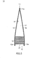
- a width direction of the bag 10 is also referred to as a first direction D1.
- the above-described pair of side portions 13 and 14 is opposite to each other in the first direction D1.
- a direction orthogonal to the first direction D1 is also referred to as a second direction D2.
- the width direction of the bag 10 may be referred to as a horizontal direction or a left-right direction.
- a direction orthogonal to the width direction of the bag 10 may be referred to as a vertical direction.
- the steam-releasing seal part 20a of the steam-releasing mechanism 20 has a shape that easily peels off as the pressure in the storage section 18 increases.
- the steam-releasing seal part 20a has a shape that protrudes from the first side seal section 13a toward the inside of the bag 10.
- a force applied to the steam-releasing seal part 20a can be greater than a force applied to the first side seal section 13a.
- a width of the steam-releasing seal part 20a is smaller than that of the first side seal section 13a.
- a non-seal section 20b isolated from the storage section 18 by the steam-releasing seal part 20a is formed between the steam-releasing seal part 20a and the outer edge of the first side portions 13.
- the front surface film 15 and the back surface film 16 constituting the laminated body 50 are prepared.
- the folded lower film 17 is inserted between the front surface film 15 and the back surface film 16.
- the inner surfaces of each film are heat-sealed together to form the seal section of the lower seal section 12a, the side seal sections 13a and 14a, the steam-releasing seal part 20a, and the like.
- the films joined to each other by the heat sealing are cut into an appropriate shape to obtain the bag 10 illustrated in FIG. 1 .
- contents 19 are filled into the bag 10 via the opening 11b of the upper portion 11.
- a bag of a type in which the non-seal section 20b of the steam-releasing mechanism 20 is surrounded by the steam-releasing seal part 20a and the first side seal section 13a is called a type 2 bag.
- the layer other than the sealant film 70 in the laminated body 50 is the same as in the first embodiment.
- a first plastic film 62 a first adhesive layer 64, a second plastic film 66, and a second adhesive layer 68, those similar to those in the first embodiment can be used.
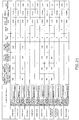
- Hot seal strengths of test pieces 90 were each measured in the same manner as in Example C1, except that the measurement of the seal strength was performed in the environment of a temperature of 100°C and a relative humidity of 50%. The results are shown in the row of the "heat seal strength (pre-retort treatment)" in FIG. 19 .
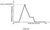
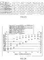
- FIG. 20 illustrates a graph obtained by plotting the seal strength against the seal temperature.
- the hot seal strength also tended to increase as the seal temperature increased, or the dependence on the seal temperature was smaller than in the case of the room-temperature seal strength.
- the ZK207 has a lower tensile elongation than ZK500. Specifically, the tensile elongation of the ZK207 in a machine direction (MD) is 790% when the thickness is 50 ⁇ m and 730% when the thickness is 60 ⁇ m.
- MD machine direction
- the bag according to the third embodiment further includes a non-seal section isolated from the storage section by the steam-releasing seal part, and the non-seal section extends from a position closer to a center point side of the storage section than the outer edge seal part to the outer edge of the bag.
- the layer other than the sealant film 70 in the laminated body 50 is the same as in the first embodiment.
- a first plastic film 62 a first adhesive layer 64, a second plastic film 66, and a second adhesive layer 68, those similar to those in the first embodiment can be used.
- the layer configuration of the laminated body 50 is not limited to the above as long as the room-temperature seal strength can be set to be 60 N or less.
- the laminated body 50 may include only one plastic film.
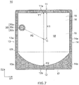
- the first edge portion 20b1 extends in a direction inclined with respect to the second direction D2 so that the first edge portion 20b1 is displaced to the opening 20p side of the side edge toward the upper portion 11. Thereby, the steam flowing from the storage section 18 into the non-seal section 20b through the position of the connection part 20b3 can be smoothly guided to the opening 20p.
- An angle ⁇ 1 formed by the direction in which the first edge portion 20b1 extends and the second direction D2 is, for example, 1° or more, preferably 10° or more, or 20° or more, and more preferably 30° or more.
- a seal section is configured so that room-temperature seal strength is 60 N or less.
- room-temperature seal strength is 60 N or less.
- the steam-releasing seal part 20a can peel off before the temperature of the contents 19 stored in the bag 10 becomes excessively high or the pressure of the contents 19 becomes excessively high. Therefore, it is possible to suppress the formation of holes in the laminated body 50 of the bag 10 or the formation of wrinkles in the laminated body 50 during the heating.
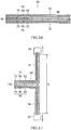
- first plastic film 62, the second plastic film 66, and the sealant film 70 were laminated by a dry lamination method to produce the laminated body 50.
- a first adhesive layer 64 and a second adhesive layer 68 a two-pack type polyurethane-based adhesive (main agent: RU-40, curing agent: H-4) manufactured by Rock Paint Co., Ltd., was used.
- the RU-40 of the main agent is polyester polyol. Thicknesses of the first adhesive layer 64 and the second adhesive layer 68 were 3.5 ⁇ m.
- a stretched PET film having a thickness of 12 ⁇ m was prepared.
- a second plastic film 66 a stretched PET film having a thickness of 12 ⁇ m was prepared.
- a sealant film 70 an unstretched polypropylene film ZK207 manufactured by Toray Film Processing Co., Ltd., was prepared. ZK207 contains the above-described propylene/ethylene block copolymer. A thickness of the sealant film 70 was 70 ⁇ m.
- the room-temperature seal strength and the hot seal strength were 65 N and 23 N, respectively.
- the room-temperature seal strength and the hot seal strength were each measured using the test piece 90 that is subjected to the retort treatment. As a result, the room-temperature seal strength and the hot seal strength were 60 N and 23 N, respectively.
- the type 1 bag 10 including the steam releasing mechanism 20 illustrated in FIGS. 1 and 4 was manufactured by using the laminated body 50.
- a height S1 of the bag 10 was 145 mm, and a width S2 thereof was 140 mm.
- a height S3 of a folded lower film 17, that is, a height from a lower end portion of the bag 10 to a folded part 17f was 40 mm.
- the bag 10 having the height S1 of 145 mm, the width S2 of 140 mm, and the height S3 of 40 mm is also referred to as an S-sized bag 10.
- the seal temperature was set to be the above-described third seal temperature
- 100 g of contents containing a large amount of oil content was filled into the S-sized type 1 bag 10, and the upper portion 11 was heat-sealed to form the upper seal section 11a.
- the bag 10 storing the contents was heated for 2 minutes using the microwave oven having an output of 500 W, and it was confirmed whether the laminated body 50 constituting the bag 10 was damaged. As a result, it was confirmed that there were no holes in the laminated body 50 in all ten bags 10.
- an S-sized type 1 bag 10 was produced using the laminated body 50 at the fourth seal temperature. Thereafter, in the same manner as in Example F1, while measuring a pressure in a storage section 18 using a sensor 81, the water in the bag 10 was heated using a microwave oven having an output of 500 W, and a peeling off pressure was measured. As a result, the peeling off pressure was 125.9 kPa.
- the seal temperature was set to be the above-described fifth seal temperature
- the S-sized type 1 bag 10 was manufactured in the same manner as in Example F8. Thereafter, in the same manner as in Example F8, while measuring a pressure in a storage section 18 using a sensor 81, the water in the bag 10 was heated using a microwave oven having an output of 500 W, and a peeling off pressure was measured. As a result, the peeling off pressure was 122.2 kPa.
- the seal temperature was set to be the above-described seventh seal temperature
- 100 g of contents containing a large amount of oil content was filled into the S-sized type 1 bag 10, and the upper portion 11 was heat-sealed to form the upper seal section 11a.
- the bag 10 storing the contents was heated for 2 minutes using the microwave oven having an output of 500 W, and it was confirmed whether the laminated body 50 constituting the bag 10 was damaged. As a result, it was confirmed that there were no holes in the laminated body 50 in all ten bags 10.
- An S-sized type 3 bag 10 was manufactured using the same laminated body 50 as in Example F1. Subsequently, in the same manner as in Example F1, 100 ml of water was filled into the bag 10, and an upper portion 11 was heat-sealed to form an upper seal section. Thereafter, in the same manner as in Example F1, while measuring a pressure in a storage section 18 using a sensor 81, the water in the bag 10 was heated using a microwave oven having an output of 500 W, and a peeling off pressure was measured. As a result, the peeling off pressure was 122.1 kPa.
- the S-sized type 3 bag 10 was manufactured using the laminated body 50. Subsequently, 100 g of contents containing a large amount of oil content was filled into the bag 10, and an upper portion 11 was heat-sealed to form an upper seal section 11a. Thereafter, the bag 10 storing the contents was heated for 2 minutes using the microwave oven having an output of 500 W, and it was confirmed whether the laminated body 50 constituting the bag 10 was damaged. As a result, it was confirmed that there were no holes in the laminated body 50 in all ten bags 10.
- the fourth embodiment has been made to solve the above problem. That is, an object of the fourth embodiment is to provide a pouch that can normally release steam from a steam-releasing mechanism and that is unlikely to overturn during the heating,
- the pouch according to the fourth embodiment further includes a lower seal section that seals between the lower portion of the front surface film and the lower film and between the lower portion of the back surface film and the lower film, in which the lower film includes a folding portion that is folded to the storage space side between the front surface film and the back surface film, and when a distance from a lower edge of the pouch to the folding portion of the lower film is set to be D11 and a minimum distance from a lower end of the pouch to an inner edge of the lower seal section is D12, D12/D11 may be 0.15 or more and 0.25 or less.
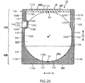
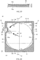
- FIG. 26 is a front view of the pouch according to the embodiment
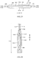
- FIG. 27 is a top view of the pouch illustrated in FIG. 26
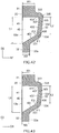
- FIG. 28 is an enlarged side view of a portion of the pouch illustrated in FIG. 26
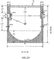
- FIG. 29 is a plan view for explaining dimensions of each component of the pouch illustrated in FIG. 26
- FIG. 30 is a perspective view of the pouch illustrated in FIG. 26 which is in an unfolded state
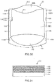
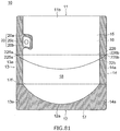
- FIG. 31 is a cross-sectional view of a laminated film.
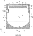
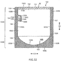
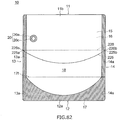
- FIG. 32 is a front view of another pouch according to the embodiment
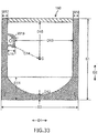
- FIG. 33 is a plan view for explaining dimensions of each component of the pouch illustrated in FIG. 32 .
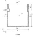
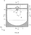
- the lower film 113 has a semicircular cutout 13B near the lower end on both edges in the horizontal direction D1. Since the lower film 113 is folded into two, the cutout 13B is provided so that the overlapping portion of the lower film 113 penetrates. By providing such a cutout 13B, the front surface film 111 and the back surface film 112 can be directly heat-sealed in the lower seal section 118 as described later.
- the shape of the cutout 13B is a semicircle, but the shape thereof is not limited.
- the cutout 13B may be a polygon such as a triangle or a quadrangle.
- the lower seal section 118 includes an auxiliary seal section 118B formed near the lower ends of both edges in the horizontal direction D1 by directly heat-sealing the front surface film 111 and the back surface film 112, as illustrated in FIG. 28 .
- the auxiliary seal section 118B is formed by heat-sealing the front surface film 111 and the back surface film 112 in the cutout 13B of the lower film 113.
- the lower seal section 118 includes a front surface portion 118C including the front surface film 111 and the lower film 113 and a back surface portion 118D including the back surface film 112 and the lower film 113 as illustrated in FIG. 28 .
- the first side seal section 156 and the second side seal section 157 are opposite to each other in the horizontal direction D1.
- the first side seal section 156 and the second side seal section 157 are not divided into the upper side seal sections 119 and 121 and the lower side seal sections 120 and 122 in contrast to the above-described pouch 10.
- the first side seal section 156 and the second side seal section 157 have a constant width and extend along the vertical direction D2 to be connected to the lower seal section 158.
- a width W17 (see FIG. 33 ) of the first side seal section 156 and a width W18 (see FIG. 33 ) of the second side seal section 157 are set to be, for example, 8 mm or more and 15 mm or less.
- notches 156B and 157B which can serve as a starting point for opening, are formed in the upper portions of the first side seal section 156 and the second side seal section 157, respectively.
- the D13/S2 which is the ratio of the distance D13 (see FIG. 33 ) from the protruding seal section 160 to an inner edge 157A of the second side seal section 157 to the width S2 of the bag 150, is preferably 0.76 or more. If the D13/S2 is 0.76 or more, even when the protruding seal section 160 is provided, the filling port is large, so that the contents can be easily filled when being filled.
- the lower limit of D13/S2 is more preferably 0.80 or more.
- the ratio S2/S1 which is the width S2 of the pouch 10 to the height S1 of the pouch 10 is 1.11 or less, so the width S2 of the pouch 10 to the height S1 of the pouch 10 is designed to be in an appropriate range so that the steam-releasing from the steam-releasing mechanism 114 can be normally performed.
- the steam can be normally released from the steam-releasing mechanism 114 during the heating.
- the steam can be normally released from the steam-releasing mechanism 114 during the heating.
- Example G5 a standing type pouch illustrated in FIG. 32 was produced. Specifically, first, a front surface film, a back surface film, and a lower film were prepared. The front surface film, the back surface film, and the lower film were one composed of a laminated film in which a base layer composed of a biaxially stretched polyethylene terephthalate film, a joint layer composed of a polyurethane-based adhesive, an intermediate layer composed of a biaxially stretched nylon film, a joint layer composed of a polyurethane-based adhesive, and a sealant layer composed of an unstretched polypropylene film are laminated in this order.
- a base layer composed of a biaxially stretched polyethylene terephthalate film
- a joint layer composed of a polyurethane-based adhesive
- an intermediate layer composed of a biaxially stretched nylon film
- a joint layer composed of a polyurethane-based adhesive a sealant layer composed of an unstretched polypropylene film
- Each pouch according to Examples G1 to G5 and Comparative Examples G1 and G2 was put in a microwave oven (model number "RE-S5C-W", manufactured by SHARP Co., Ltd.) having an inside height of 150 mm in a self-standing state, and heated for 2 minutes and 30 seconds at 600 W. In the pouch heated, it was evaluated whether or not the pouch overturns, whether or not the pouch rotates at the same time as steam was released, and whether or not the steam was automatically released from the steam-releasing mechanism, respectively.
- the evaluation criteria were as follows.
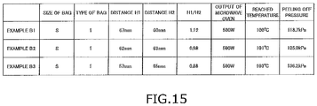
- Example G1 147 160 46 10 135 1.09 0.22 0.84 200g of water great good
- Example G2 145 150 43 10 125 1.03 0.23 0.83 170g of water great good
- Example G3 145 140 40 9 115 0.97 0.23 0.82 130g of water fire at good
- Example G4 147 160 46 6 135 1.09 0.13 0.84 200g of water good good
- Example G5 147 160 46 10 125 1.09 0.22 0.78 200g of water great good
- Comparative Example G1 155 157 46 10 132 1.01 0.22 0.84 200g of water bad - Comparative Example G2 147 170 46 10 145 1.16 0.22 0.85 200g of water great bad
- the pouches according to Examples G1 to G5 did not overturn during the heating, and the steam was normally released from the steam-releasing mechanism. It is considered that this is because the height of the pouch was lower than the height of the inside of the microwave oven and the S2/S1, which is the ratio of the width of the pouch to the height of the pouch, was in an appropriate range.
- the second non-seal section 45 having such a shape is formed at the same time as the first non-seal section 40 by cutting one non-seal section as disclosed in, for example, JP 2016-74457 A .
- one of the cut non-seal section becomes the first non-seal section 40 and the other thereof becomes the second non-seal section 45.
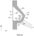
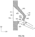
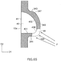
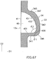
- first edge portion 431, the second edge portion 432, and the third edge portion 433 all extend linearly. Further, the first connection part 436 is opposite to the inner edge first connection part 346, and the second connection part 437 is opposite to the inner edge second connection part 347.
- reference signs W1 and W2 each denote the width of the upper side seal part 31 and the width of the lower side seal part 32.
- the width W1 of the upper side seal part 31 and the width W2 of the lower side seal part 32 are, for example, 4 mm or more and 15 mm or less.
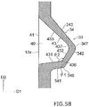
- first inner edge 341 of the inner edge 34 of the intermediate seal part 33 extends substantially in the left-right direction D1 from the inner edge first connection part 346 toward the lower side seal part 32.
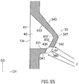
- the present invention is not limited thereto, and for example, as illustrated in FIG. 58 , the first inner edge 341 may extend to be displaced to the lower portion 12 side from the inner edge first connection part 346 toward the lower side seal part 32.
- the angle ⁇ 1 formed by the direction in which the first inner edge 341 extends and the direction in which the second inner edge 342 extends is, for example, 95° or more and 170° or less.
- the inner edge connection parts such as the inner edge first connection part 346 and the inner edge second connection part 347 are defined as portions where the direction in which the inner edge 34 extends changes.
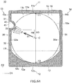
- a width S22 and a depth S23 of the non-through hole 227 of the first half-cut line 225 and the second half-cut line 226 are set so that the first half-cut line 225 and the second half-cut line 226 are broken when the user applies an appropriate force to the bag 10.
- the width S22 of the non-through hole 227 is 10 ⁇ m or more and 1 mm or less.
- the depth S23 of the non-through hole 227 is, for example, 5 ⁇ m or more and 10 ⁇ m or less.
- Such a non-through hole 227 can be formed, for example, by processing the laminated body 50 by irradiating laser light from the outer surface 50y side to the laminated body 50.
- the non-through hole 227 may be formed by processing the laminated body 50 from the outer surface 50y side using a cutting blade or the like.
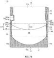
- one end 225a of the first half-cut line 225 and one end 226a of the second half-cut line 226 that are positioned at the first side portion 13 are positioned below the steam-releasing mechanism 20. For this reason, by tearing the bag 10 along the first half-cut line 225 and the second half-cut line 226, as illustrated in FIG. 75 , the steam-releasing mechanism 20 cannot remain in the opened bag 10.
- one end 225a of the first half-cut line 225 and one end 226a of the second half-cut line 226 may be positioned at the first side portion 13 below the steam-releasing mechanism 20, and the other end 225b of the first half-cut line 225 and the other end 226b of the second half-cut line 226 may be positioned at the upper portion 11 of the bag 10.
- the opened bag 10 since there are a lot of portions on the second side portion 14 side, a consumer can hold the portion on the second side portion 14 side by hand or the like. Thereby, the posture of the bag 10 is easily controlled, so the ease of taking out the contents can be improved.
- first half-cut line 225 and the second half-cut line 226 may be at least partially separated in the vertical direction.
- the distance H21 in the vertical direction between one end 225a or the other end 225b of the first half-cut line 225 and the lowermost part of the first half-cut line 225 is, for example, 20 mm or more and preferably 30 mm or more.
- the distance H21 is, for example, 70 mm or less and preferably 50 mm or less.
Landscapes
- Engineering & Computer Science (AREA)
- Mechanical Engineering (AREA)
- Chemical & Material Sciences (AREA)
- Life Sciences & Earth Sciences (AREA)
- Food Science & Technology (AREA)
- Health & Medical Sciences (AREA)
- Chemical Kinetics & Catalysis (AREA)
- Medicinal Chemistry (AREA)
- Polymers & Plastics (AREA)
- Organic Chemistry (AREA)
- Package Specialized In Special Use (AREA)
- Bag Frames (AREA)
Applications Claiming Priority (7)
| Application Number | Priority Date | Filing Date | Title |
|---|---|---|---|
| JP2017166916A JP7476454B2 (ja) | 2017-08-31 | 2017-08-31 | パウチ |
| JP2017179489A JP7297405B2 (ja) | 2017-09-19 | 2017-09-19 | 袋 |
| JP2017244337A JP7309319B2 (ja) | 2017-12-20 | 2017-12-20 | パウチ |
| JP2018015915 | 2018-01-31 | ||
| JP2018035600A JP2019151343A (ja) | 2018-02-28 | 2018-02-28 | 袋 |
| JP2018053336A JP2019163080A (ja) | 2018-03-20 | 2018-03-20 | 袋及び袋の製造方法 |
| PCT/JP2018/032263 WO2019045019A1 (fr) | 2017-08-31 | 2018-08-30 | Sac |
Publications (4)
| Publication Number | Publication Date |
|---|---|
| EP3677529A1 true EP3677529A1 (fr) | 2020-07-08 |
| EP3677529A4 EP3677529A4 (fr) | 2021-06-09 |
| EP3677529B1 EP3677529B1 (fr) | 2025-11-19 |
| EP3677529C0 EP3677529C0 (fr) | 2025-11-19 |
Family
ID=65527209
Family Applications (1)
| Application Number | Title | Priority Date | Filing Date |
|---|---|---|---|
| EP18849976.8A Active EP3677529B1 (fr) | 2017-08-31 | 2018-08-30 | Sac |
Country Status (3)
| Country | Link |
|---|---|
| US (1) | US11535426B2 (fr) |
| EP (1) | EP3677529B1 (fr) |
| WO (1) | WO2019045019A1 (fr) |
Families Citing this family (11)
| Publication number | Priority date | Publication date | Assignee | Title |
|---|---|---|---|---|
| JP7245445B2 (ja) * | 2018-02-28 | 2023-03-24 | 大日本印刷株式会社 | 積層体及び該積層体で構成される袋 |
| JP7298303B2 (ja) * | 2019-05-28 | 2023-06-27 | 大日本印刷株式会社 | 蓋付容器 |
| JP2021004049A (ja) * | 2019-06-25 | 2021-01-14 | 大日本印刷株式会社 | パウチ |
| JPWO2021049385A1 (fr) * | 2019-09-09 | 2021-03-18 | ||
| JP2021075289A (ja) * | 2019-11-06 | 2021-05-20 | 東洋製罐株式会社 | 電子レンジ用パウチ |
| EP4105142A4 (fr) * | 2020-02-14 | 2023-07-12 | Toppan Inc. | Film d'emballage de congélation, sac d'emballage de congélation, emballage d'aliment congelé et procédé d'évaluation de propriétés de stockage d'un film d'emballage de congélation |
| WO2021206150A1 (fr) * | 2020-04-08 | 2021-10-14 | 凸版印刷株式会社 | Pochette |
| EP3956236A4 (fr) | 2020-06-19 | 2024-01-03 | ProAmpac Holdings Inc. | Poches à soufflets à base de polyester stratifié, souples, prêtes à être recyclées |
| JP2023074721A (ja) * | 2021-11-18 | 2023-05-30 | 出光ユニテック株式会社 | ジッパーテープ付き容器 |
| US12509291B2 (en) | 2023-10-24 | 2025-12-30 | Amcor Flexibles North America, Inc. | Microwave package with low pressure venting feature |
| CN222409255U (zh) * | 2024-04-26 | 2025-01-28 | 宝洁公司 | 包装袋和带有包装袋的洗涤用产品 |
Family Cites Families (42)
| Publication number | Priority date | Publication date | Assignee | Title |
|---|---|---|---|---|
| JPS5941569B2 (ja) | 1977-04-11 | 1984-10-08 | キヤノン株式会社 | 原稿圧着装置 |
| US4759472A (en) * | 1986-04-17 | 1988-07-26 | Hays Macfarland & Associates | Container having a pressure-rupturable seal for dispensing contents |
| US4890744A (en) * | 1988-10-28 | 1990-01-02 | W. A. Lane, Inc. | Easy open product pouch |
| US5195658A (en) * | 1991-03-12 | 1993-03-23 | Toyo Bussan Kabushiki Kaisha | Disposable container |
| JPH09328145A (ja) | 1996-06-10 | 1997-12-22 | Kanebo Ltd | 液体包装容器 |
| JPH10101154A (ja) | 1996-09-30 | 1998-04-21 | Sun A Kaken Co Ltd | 加熱処理用包装袋 |
| JP3776555B2 (ja) | 1997-03-27 | 2006-05-17 | 大日本印刷株式会社 | レトルト処理用積層体 |
| JPH11279392A (ja) | 1998-03-31 | 1999-10-12 | Japan Atom Energy Res Inst | 分解性テープ |
| PL196345B1 (pl) * | 2001-12-14 | 2007-12-31 | Huhtamaki Ronsberg | Opakowanie i narzędzie do wykonywania uszczelnienia |
| JP3846380B2 (ja) | 2002-08-19 | 2006-11-15 | 宇部興産株式会社 | 積層フィルム及び積層体 |
| JP4421828B2 (ja) * | 2003-03-07 | 2010-02-24 | 日本合成化学工業株式会社 | 多層容器 |
| US20050255200A1 (en) * | 2004-05-17 | 2005-11-17 | Dai Nippon Printing Co., Ltd. | Food packaging bag, food-packaged body, and method for manufacturing the same |
| US20050276885A1 (en) * | 2004-06-10 | 2005-12-15 | Bennett James A | Self-venting microwaveable pouch, food item, and method of preparation |
| JP4960103B2 (ja) | 2004-11-29 | 2012-06-27 | 東レフィルム加工株式会社 | ポリプロピレン系フィルムおよびその積層体 |
| US8434637B2 (en) * | 2005-04-04 | 2013-05-07 | Dai Nippon Printing Co., Ltd | Packaging bag |
| JP2007284118A (ja) | 2006-04-18 | 2007-11-01 | Toppan Printing Co Ltd | 蒸気抜き包装袋 |
| JP5493115B2 (ja) * | 2006-06-28 | 2014-05-14 | 藤森工業株式会社 | 液体収納容器 |
| US20100266732A1 (en) * | 2009-04-20 | 2010-10-21 | Fres-Co System Usa, Inc. | Microwavable self-venting package |
| JP2011037459A (ja) | 2009-08-07 | 2011-02-24 | Toppan Printing Co Ltd | ヘッダー付包装袋およびこれを用いた包装体 |
| JP5632226B2 (ja) * | 2010-07-30 | 2014-11-26 | 株式会社細川洋行 | 医療用多層チューブ、および医療用輸液バッグ |
| JP5887745B2 (ja) | 2011-07-26 | 2016-03-16 | 凸版印刷株式会社 | 電子レンジ加熱用容器 |
| JP6425870B2 (ja) * | 2011-09-30 | 2018-11-21 | 大日本印刷株式会社 | シーラント、それを用いた積層体および電子レンジ用包装袋 |
| JP6053281B2 (ja) | 2011-12-28 | 2016-12-27 | 大日本印刷株式会社 | 電子レンジ加熱用袋 |
| CN104144859B (zh) | 2012-03-07 | 2016-05-18 | 凸版印刷株式会社 | 蒸气排出自立袋及密封有内容物的自立袋 |
| JP6065420B2 (ja) | 2012-06-13 | 2017-01-25 | 凸版印刷株式会社 | 蒸気抜きスタンディングパウチ |
| JP5994621B2 (ja) | 2012-12-18 | 2016-09-21 | 大日本印刷株式会社 | 液体収容袋の製造方法および液体収容袋 |
| JP6221986B2 (ja) | 2013-11-20 | 2017-11-01 | 大日本印刷株式会社 | パウチ |
| JP6277485B2 (ja) | 2014-03-07 | 2018-02-14 | 東レフィルム加工株式会社 | ポリプロピレン系フィルムおよびそれを用いた積層体 |
| JP6331595B2 (ja) * | 2014-03-31 | 2018-05-30 | 大日本印刷株式会社 | パウチ |
| US10160186B2 (en) * | 2014-08-26 | 2018-12-25 | Dow Global Technologies Llc | Coextruded multilayer film with filler in transport layer |
| JP6425122B2 (ja) | 2014-10-06 | 2018-11-21 | 大日本印刷株式会社 | パウチ |
| JP6476800B2 (ja) | 2014-12-02 | 2019-03-06 | 凸版印刷株式会社 | 包装袋 |
| JP5941569B1 (ja) | 2015-02-25 | 2016-06-29 | 凸版印刷株式会社 | 包装袋 |
| JP6699282B2 (ja) * | 2015-03-26 | 2020-05-27 | 東洋製罐株式会社 | 電子レンジ用パウチ |
| JP2017024746A (ja) | 2015-07-21 | 2017-02-02 | 凸版印刷株式会社 | 蒸気抜きスタンディングパウチ |
| US20190193904A1 (en) * | 2015-08-31 | 2019-06-27 | Toray Advanced Film Co., Ltd | Polypropylene based sealant film for retort packaging, and laminate that uses the same |
| JP2017071424A (ja) | 2015-10-08 | 2017-04-13 | 凸版印刷株式会社 | 自立性フィルム容器 |
| WO2017135124A1 (fr) * | 2016-02-03 | 2017-08-10 | 凸版印刷株式会社 | Feuille laminée et manchon de récipient d'emballage |
| JP6128623B1 (ja) * | 2016-03-08 | 2017-05-17 | 大成ラミック株式会社 | 包装袋および包装袋の使用方法 |
| CN109789959B (zh) * | 2016-09-23 | 2020-08-11 | 东洋制罐株式会社 | 微波炉加热用包装袋 |
| JP6929068B2 (ja) * | 2017-01-20 | 2021-09-01 | 共同印刷株式会社 | 包装袋及びその製造方法 |
| JP6222394B2 (ja) | 2017-05-15 | 2017-11-01 | 大日本印刷株式会社 | パウチ |
-
2018
- 2018-08-30 US US16/642,691 patent/US11535426B2/en active Active
- 2018-08-30 WO PCT/JP2018/032263 patent/WO2019045019A1/fr not_active Ceased
- 2018-08-30 EP EP18849976.8A patent/EP3677529B1/fr active Active
Also Published As
| Publication number | Publication date |
|---|---|
| EP3677529B1 (fr) | 2025-11-19 |
| US20200198841A1 (en) | 2020-06-25 |
| WO2019045019A1 (fr) | 2019-03-07 |
| US11535426B2 (en) | 2022-12-27 |
| EP3677529C0 (fr) | 2025-11-19 |
| EP3677529A4 (fr) | 2021-06-09 |
Similar Documents
| Publication | Publication Date | Title |
|---|---|---|
| EP3677529B1 (fr) | Sac | |
| KR101702149B1 (ko) | 다층 적층 개봉 용이 포장체 | |
| JP7377464B2 (ja) | 積層体及び該積層体で構成される袋 | |
| EP3517457B1 (fr) | Sac d'emballage pour un chauffage au four à micro-ondes | |
| JP7449493B2 (ja) | 積層体及び該積層体で構成される袋 | |
| JP7505529B2 (ja) | 積層体で構成される袋 | |
| JP7599815B2 (ja) | 袋 | |
| JP7659366B2 (ja) | 袋 | |
| JP7729416B2 (ja) | 包装材料及び包装材料を備える包装製品 | |
| JP2023017060A (ja) | 袋 | |
| JP7389959B2 (ja) | 包装材料及び包装材料を備えるパウチ | |
| JP2023097273A (ja) | パウチ | |
| JP7682601B2 (ja) | 包装材料及び包装材料を備える袋 | |
| JP7733878B2 (ja) | パウチ | |
| JP2020055628A (ja) | パウチ | |
| JP7667953B2 (ja) | パウチ | |
| JP7641495B2 (ja) | パウチ | |
| JP7847935B2 (ja) | 袋 | |
| JP2019163080A (ja) | 袋及び袋の製造方法 | |
| JP2023051548A (ja) | パウチ | |
| JP2023051541A (ja) | パウチ | |
| JP2022075970A (ja) | 袋及び袋の製造方法 | |
| JP2024008288A (ja) | 包装材料及びパウチ | |
| JP2023051551A (ja) | パウチ | |
| JP7385822B2 (ja) | 包装材料及び包装材料を備える包装製品 |
Legal Events
| Date | Code | Title | Description |
|---|---|---|---|
| STAA | Information on the status of an ep patent application or granted ep patent |
Free format text: STATUS: THE INTERNATIONAL PUBLICATION HAS BEEN MADE |
|
| PUAI | Public reference made under article 153(3) epc to a published international application that has entered the european phase |
Free format text: ORIGINAL CODE: 0009012 |
|
| STAA | Information on the status of an ep patent application or granted ep patent |
Free format text: STATUS: REQUEST FOR EXAMINATION WAS MADE |
|
| 17P | Request for examination filed |
Effective date: 20200310 |
|
| AK | Designated contracting states |
Kind code of ref document: A1 Designated state(s): AL AT BE BG CH CY CZ DE DK EE ES FI FR GB GR HR HU IE IS IT LI LT LU LV MC MK MT NL NO PL PT RO RS SE SI SK SM TR |
|
| AX | Request for extension of the european patent |
Extension state: BA ME |
|
| DAV | Request for validation of the european patent (deleted) | ||
| DAX | Request for extension of the european patent (deleted) | ||
| A4 | Supplementary search report drawn up and despatched |
Effective date: 20210511 |
|
| RIC1 | Information provided on ipc code assigned before grant |
Ipc: B65D 81/34 20060101AFI20210504BHEP |
|
| STAA | Information on the status of an ep patent application or granted ep patent |
Free format text: STATUS: EXAMINATION IS IN PROGRESS |
|
| 17Q | First examination report despatched |
Effective date: 20230208 |
|
| GRAP | Despatch of communication of intention to grant a patent |
Free format text: ORIGINAL CODE: EPIDOSNIGR1 |
|
| STAA | Information on the status of an ep patent application or granted ep patent |
Free format text: STATUS: GRANT OF PATENT IS INTENDED |
|
| INTG | Intention to grant announced |
Effective date: 20250613 |
|
| GRAS | Grant fee paid |
Free format text: ORIGINAL CODE: EPIDOSNIGR3 |
|
| GRAA | (expected) grant |
Free format text: ORIGINAL CODE: 0009210 |
|
| STAA | Information on the status of an ep patent application or granted ep patent |
Free format text: STATUS: THE PATENT HAS BEEN GRANTED |
|
| AK | Designated contracting states |
Kind code of ref document: B1 Designated state(s): AL AT BE BG CH CY CZ DE DK EE ES FI FR GB GR HR HU IE IS IT LI LT LU LV MC MK MT NL NO PL PT RO RS SE SI SK SM TR |
|
| REG | Reference to a national code |
Ref country code: CH Ref legal event code: F10 Free format text: ST27 STATUS EVENT CODE: U-0-0-F10-F00 (AS PROVIDED BY THE NATIONAL OFFICE) Effective date: 20251119 Ref country code: GB Ref legal event code: FG4D |
|
| REG | Reference to a national code |
Ref country code: DE Ref legal event code: R096 Ref document number: 602018087326 Country of ref document: DE |
|
| REG | Reference to a national code |
Ref country code: IE Ref legal event code: FG4D |
|
| U01 | Request for unitary effect filed |
Effective date: 20251202 |
|
| U07 | Unitary effect registered |
Designated state(s): AT BE BG DE DK EE FI FR IT LT LU LV MT NL PT RO SE SI Effective date: 20251223 |
|
| PG25 | Lapsed in a contracting state [announced via postgrant information from national office to epo] |
Ref country code: ES Free format text: LAPSE BECAUSE OF FAILURE TO SUBMIT A TRANSLATION OF THE DESCRIPTION OR TO PAY THE FEE WITHIN THE PRESCRIBED TIME-LIMIT Effective date: 20251119 |
|
| PG25 | Lapsed in a contracting state [announced via postgrant information from national office to epo] |
Ref country code: NO Free format text: LAPSE BECAUSE OF FAILURE TO SUBMIT A TRANSLATION OF THE DESCRIPTION OR TO PAY THE FEE WITHIN THE PRESCRIBED TIME-LIMIT Effective date: 20260219 |
|
| PG25 | Lapsed in a contracting state [announced via postgrant information from national office to epo] |
Ref country code: HR Free format text: LAPSE BECAUSE OF FAILURE TO SUBMIT A TRANSLATION OF THE DESCRIPTION OR TO PAY THE FEE WITHIN THE PRESCRIBED TIME-LIMIT Effective date: 20251119 |
|
| PG25 | Lapsed in a contracting state [announced via postgrant information from national office to epo] |
Ref country code: RS Free format text: LAPSE BECAUSE OF FAILURE TO SUBMIT A TRANSLATION OF THE DESCRIPTION OR TO PAY THE FEE WITHIN THE PRESCRIBED TIME-LIMIT Effective date: 20260219 |
|
| PG25 | Lapsed in a contracting state [announced via postgrant information from national office to epo] |
Ref country code: IS Free format text: LAPSE BECAUSE OF FAILURE TO SUBMIT A TRANSLATION OF THE DESCRIPTION OR TO PAY THE FEE WITHIN THE PRESCRIBED TIME-LIMIT Effective date: 20260319 |
|
| PG25 | Lapsed in a contracting state [announced via postgrant information from national office to epo] |
Ref country code: PL Free format text: LAPSE BECAUSE OF FAILURE TO SUBMIT A TRANSLATION OF THE DESCRIPTION OR TO PAY THE FEE WITHIN THE PRESCRIBED TIME-LIMIT Effective date: 20251119 |