EP3677554A1 - Procédé et dispositif de moulage à chaud des pièces en verre et récipients en verre moulés à chaud - Google Patents
Procédé et dispositif de moulage à chaud des pièces en verre et récipients en verre moulés à chaud Download PDFInfo
- Publication number
- EP3677554A1 EP3677554A1 EP19197214.0A EP19197214A EP3677554A1 EP 3677554 A1 EP3677554 A1 EP 3677554A1 EP 19197214 A EP19197214 A EP 19197214A EP 3677554 A1 EP3677554 A1 EP 3677554A1
- Authority
- EP
- European Patent Office
- Prior art keywords
- shaping
- glass
- workpiece
- roller
- slope
- Prior art date
- Legal status (The legal status is an assumption and is not a legal conclusion. Google has not performed a legal analysis and makes no representation as to the accuracy of the status listed.)
- Granted
Links
Images

Classifications
-
- C—CHEMISTRY; METALLURGY
- C03—GLASS; MINERAL OR SLAG WOOL
- C03B—MANUFACTURE, SHAPING, OR SUPPLEMENTARY PROCESSES
- C03B13/00—Rolling molten glass, i.e. where the molten glass is shaped by rolling
- C03B13/16—Construction of the glass rollers
-
- C—CHEMISTRY; METALLURGY
- C03—GLASS; MINERAL OR SLAG WOOL
- C03B—MANUFACTURE, SHAPING, OR SUPPLEMENTARY PROCESSES
- C03B23/00—Re-forming shaped glass
- C03B23/18—Re-forming and sealing ampoules
-
- A—HUMAN NECESSITIES
- A61—MEDICAL OR VETERINARY SCIENCE; HYGIENE
- A61J—CONTAINERS SPECIALLY ADAPTED FOR MEDICAL OR PHARMACEUTICAL PURPOSES; DEVICES OR METHODS SPECIALLY ADAPTED FOR BRINGING PHARMACEUTICAL PRODUCTS INTO PARTICULAR PHYSICAL OR ADMINISTERING FORMS; DEVICES FOR ADMINISTERING FOOD OR MEDICINES ORALLY; BABY COMFORTERS; DEVICES FOR RECEIVING SPITTLE
- A61J1/00—Containers specially adapted for medical or pharmaceutical purposes
- A61J1/05—Containers specially adapted for medical or pharmaceutical purposes for collecting, storing or administering blood, plasma or medical fluids ; Infusion or perfusion containers
- A61J1/06—Ampoules or carpules
- A61J1/065—Rigid ampoules, e.g. glass ampoules
-
- A—HUMAN NECESSITIES
- A61—MEDICAL OR VETERINARY SCIENCE; HYGIENE
- A61M—DEVICES FOR INTRODUCING MEDIA INTO, OR ONTO, THE BODY; DEVICES FOR TRANSDUCING BODY MEDIA OR FOR TAKING MEDIA FROM THE BODY; DEVICES FOR PRODUCING OR ENDING SLEEP OR STUPOR
- A61M5/00—Devices for bringing media into the body in a subcutaneous, intra-vascular or intramuscular way; Accessories therefor, e.g. filling or cleaning devices, arm-rests
- A61M5/178—Syringes
- A61M5/31—Details
-
- B—PERFORMING OPERATIONS; TRANSPORTING
- B65—CONVEYING; PACKING; STORING; HANDLING THIN OR FILAMENTARY MATERIAL
- B65D—CONTAINERS FOR STORAGE OR TRANSPORT OF ARTICLES OR MATERIALS, e.g. BAGS, BARRELS, BOTTLES, BOXES, CANS, CARTONS, CRATES, DRUMS, JARS, TANKS, HOPPERS, FORWARDING CONTAINERS; ACCESSORIES, CLOSURES, OR FITTINGS THEREFOR; PACKAGING ELEMENTS; PACKAGES
- B65D13/00—Containers having bodies formed by interconnecting two or more rigid, or substantially rigid, components made wholly or mainly of the same material, other than metal, plastics, wood or substitutes therefor
- B65D13/02—Containers having bodies formed by interconnecting two or more rigid, or substantially rigid, components made wholly or mainly of the same material, other than metal, plastics, wood or substitutes therefor of glass, pottery, or other ceramic material
-
- C—CHEMISTRY; METALLURGY
- C03—GLASS; MINERAL OR SLAG WOOL
- C03B—MANUFACTURE, SHAPING, OR SUPPLEMENTARY PROCESSES
- C03B23/00—Re-forming shaped glass
- C03B23/04—Re-forming tubes or rods
- C03B23/055—Re-forming tubes or rods by rolling
-
- C—CHEMISTRY; METALLURGY
- C03—GLASS; MINERAL OR SLAG WOOL
- C03B—MANUFACTURE, SHAPING, OR SUPPLEMENTARY PROCESSES
- C03B23/00—Re-forming shaped glass
- C03B23/04—Re-forming tubes or rods
- C03B23/09—Reshaping the ends, e.g. as grooves, threads or mouths
- C03B23/095—Reshaping the ends, e.g. as grooves, threads or mouths by rolling
-
- A—HUMAN NECESSITIES
- A61—MEDICAL OR VETERINARY SCIENCE; HYGIENE
- A61M—DEVICES FOR INTRODUCING MEDIA INTO, OR ONTO, THE BODY; DEVICES FOR TRANSDUCING BODY MEDIA OR FOR TAKING MEDIA FROM THE BODY; DEVICES FOR PRODUCING OR ENDING SLEEP OR STUPOR
- A61M2205/00—General characteristics of the apparatus
- A61M2205/02—General characteristics of the apparatus characterised by a particular materials
-
- C—CHEMISTRY; METALLURGY
- C03—GLASS; MINERAL OR SLAG WOOL
- C03B—MANUFACTURE, SHAPING, OR SUPPLEMENTARY PROCESSES
- C03B13/00—Rolling molten glass, i.e. where the molten glass is shaped by rolling
- C03B13/18—Auxiliary means for rolling glass, e.g. sheet supports, gripping devices, hand-ladles, means for moving glass pots
-
- C—CHEMISTRY; METALLURGY
- C03—GLASS; MINERAL OR SLAG WOOL
- C03B—MANUFACTURE, SHAPING, OR SUPPLEMENTARY PROCESSES
- C03B2215/00—Press-moulding glass
- C03B2215/50—Structural details of the press-mould assembly
-
- C—CHEMISTRY; METALLURGY
- C03—GLASS; MINERAL OR SLAG WOOL
- C03B—MANUFACTURE, SHAPING, OR SUPPLEMENTARY PROCESSES
- C03B9/00—Blowing glass; Production of hollow glass articles
- C03B9/13—Blowing glass; Production of hollow glass articles in gob feeder machines
- C03B9/193—Blowing glass; Production of hollow glass articles in gob feeder machines in "press-and-blow" machines
Definitions
- the invention relates to a method and a device for shaping glass workpieces in a hot process.
- the invention relates to a method and a device for a corresponding forming process, which make it possible to increase the production of good items by means of increased cleaning intervals.
- the invention further relates to hollow glass objects.
- glass vials for example for pharmaceutical applications, are produced from a glass tube in which a short piece of tube is heated at one end to the shaping temperature of the glass and brought into the desired shape in one or more shaping steps using suitable shaping tools.
- the internal geometry is usually formed with mandrels that are inserted into the pipe end.
- the workpiece rotates during the molding process.
- the shape and dimensions of the mandrel define the inner geometry of the glass vial.
- the shaping is carried out by means of external molds which press the glass tube against the mandrel and at the same time form the outer side of the glass tube. This turns the glass tube and the outer mold.
- the outer die includes a shaping roll with a shaping surface
- the forming is preferably carried out on a so-called rotary clock.
- the forming can be done in several steps, i.e. at several stations of the rotary machine.
- the glass workpiece is cooled by the molding tools.
- the workpiece may therefore need to be reheated between the forming steps.
- the temperature control is designed so that after the last shaping step the glass reaches a temperature at which the workpiece is dimensionally stable.
- the glass can have temperatures of up to 1000 ° C.
- the shaping surfaces heat up during the forming process and can therefore have temperatures of> 250 ° C.
- a lubricant also referred to as a release agent, for example an oil or a paste, is generally used in the hot forming of glass described above.
- the lubricant is applied to the molds in the intermediate cycles of the molding process, in which the tools have no glass contact, for example by spraying, spraying, spraying or flushing the molds with the lubricant.
- the respective tool is lubricated again before each glass contact.
- the contours of uneven soot deposits on the form rollers can be transferred to the glass.
- the bumps are pressed onto the glass surface like a stamp, which also leads to cosmetic defects and thus to a rejection of the corresponding vials.
- the lubricant can also be trapped between the glass surface and the rotating form rollers.
- the enclosed oil film is clamped between the glass and tool surface during the rolling process and thus embosses a pattern on the still deformable glass surface. In the end product, this leads to a stain-like structure with different heights on the corresponding glass surfaces.
- There is no fundamental difference in the design of the pattern with respect to the direction i.e. there is no fundamental difference between the characteristics of the pattern in the direction of rotation, i.e. tangential, and the expression of the pattern in the direction of the axis of rotation, i.e. axially.
- the molds must therefore be cleaned at a suitable cleaning interval. This interval is typically 2 to 3 hours. In this case, the production machine must be shut down to clean the form rolls, which leads to reduced production. In addition, start-up problems can arise from the shutdown of the production machine, so that the manufacturing process is impaired beyond the shutdown period.
- An object of the invention is to provide a device for producing a glass object with a defined inner and outer geometry, which does not have the disadvantages of the prior art described above.
- Another object of the invention is to provide a corresponding manufacturing method and a hollow glass object.
- the shaping of the workpiece into the specific shape or dimensions of the desired product can be a direct result of the molding process.
- the rolled edge or the outer surface of the rolled edge in the case of vials or cartridges or in the case of syringes, the outer surface of the syringe cone can be formed with the method according to the invention.
- a shaping of the workpiece into the product shape can, however, also be achieved by several different molding processes.
- the neck and bottle mouth geometry can also be formed, for example, in the production of glass bottles, vials or containers.
- the cleaning intervals can be significantly extended with the device according to the invention. At the same time, the production-related scrap decreases. This is guaranteed by the individual components of the device.
- the device is designed in particular for shaping a tubular workpiece.
- the inner and outer surface areas are largely determined by the geometry of the pipe.
- the inner mold is designed as a mandrel.
- a corresponding device is particularly suitable for producing glass containers such as pharmaceutical primary packaging, for example vials, cartridges or syringes, by reshaping glass tubes.
- the outer shaping roller Due to the fixation of the outer shaping roller, it is not driven or set in rotation by the rotating workpiece during the shaping process. There is thus a relative movement between the outer shaping roller and the workpiece. This relative movement causes shear forces on the workpiece. Surprisingly, it has been found that this does not adversely affect the quality of the formed workpieces if the form roller is adequately lubricated. Rather, it has been found that the shear forces have a positive effect. The material to be deformed is guided by the shear forces in a particularly advantageous manner to the molding tools and pressed against them, which in turn facilitates the shaping of the workpiece.
- the form roller is locked with a detachable connection, so that the shaping roller can be released between the individual shaping processes and rotated through an angle ⁇ in the locking device.
- the angle ⁇ can be predefined according to one embodiment.
- the rotation of the shaping roller between the hot shaping processes by the angle ⁇ thus leads to the subsequent hot shaping process taking place through an adjacent surface section of the shaping surface. Only a small proportion of the surface of the form roller is used for each formed workpiece. Rotating the shaping roller between the individual shaping steps ensures uniform wear of the shaping surface over the entire surface of the shaping roller.
- Another advantage of the locking device according to the invention is that by rotating the shaping roller between the individual shaping processes in each shaping process or for each workpiece to be reshaped, a cold spot on the Molding tool is used.
- the form roll does not heat up or only very little during production. This is particularly advantageous since the soot formation is considerably reduced by combustion or pyrolysis of the lubricating oil.
- the wear of the mold is also reduced, so that the life of the mold can be extended.
- the device has a device for applying the lubricating oil to the shaping surface of the shaping roller.
- the lubricating oil is always applied to only one part of the shaping surface per application process.
- Lubricating oil is preferably applied to part of the shaping roller at each cycle.
- the device for dispensing lubricating oil is permanently installed in the device, i.e. the distance from the spray nozzle to the surface of the mold to be sprayed is constant.
- the spray nozzle for example, can be integrated into the molding station or an external molding tool. Attachment below an external mold is also possible.
- the lubricating oil is applied through a drip oiler.
- Drip oilers with automatic, regular oil dispensing have proven to be particularly advantageous.
- the device for applying the lubricating oil is preferably positioned in the device such that the outlet opening of the device for applying the lubricating oil and the molding tool are arranged at an angular distance of at least 45 ° around the axis of rotation of the workpiece. This means that there is little lubricating oil in contact with the hot glass.
- the angle ⁇ is preferably in the range from 90 to 270 °, particularly preferably in the range from 160 to 200 °, i.e. the device for applying the lubricating oil is arranged in the device on the opposite side for glass engagement.
- the amount of oil dispensed per application is in the range from 0.01 to 0.1 g, particularly preferably in the range from 0.03 to 0.05 g. Due to the small amount of applied lubricant, the contamination of the product, the molds and the production environment can be significantly reduced. At the same time, however, a sufficient lubricating effect is achieved in the device according to the invention.
- oils with a viscosity ⁇ 600 mm 2 / s and a flash point and / or pyrolysis point> 200 ° C., preferably> 250 ° C. can be used as lubricants in the device according to the invention. This means that the same oils can be used as in the known standard processes.
- the device is designed in particular for shaping a tubular workpiece.
- the inner and outer surface areas are largely determined by the geometry of the pipe.
- the inner mold is designed as a mandrel.
- a corresponding device is particularly suitable for producing glass containers such as pharmaceutical primary packaging, for example vials, cartridges or syringes, by reshaping glass tubes.
- the shaping roll has a rotationally symmetrical cross-sectional area.
- the shaping roller has a cylindrical cross section in a central plane perpendicular to the axis of rotation of the shaping roller.
- the shaping roll is thus round. This has the advantage that in step c) the angle through which the shaping roller is rotated can be freely selected, or that an exact setting of the rotation angle ⁇ is not necessary.
- the shaping roller has a polygonal cross section with a plurality of shaping surfaces in a central plane perpendicular to the axis of rotation of the shaping roller.
- the angle of rotation ⁇ to be maintained in step c) depends on the number of shaping surfaces.
- the shaping roller preferably has 6 to 18 shaping surfaces.
- the edges of the shaping surfaces are flat, convex or concave.
- the device By rotating the shaping roller according to the invention after each shaping process, a cold spot on the molding tool is used for each workpiece to be reshaped, and the shaping roller only heats up slightly during production.
- the device has an additional device for cooling the shaping roll. The cooling can take place by active or passive heat conduction.
- the device has a heat sink, which is connected directly or indirectly to the device for receiving the form roller.
- the form roller is in thermal contact with a heat sink, the heat sink preferably having a means for internal cooling so that process heat can be dissipated.
- the coolant is only indirectly in contact with the form roller via the heat sink.
- the device has air cooling for cooling the forming roll.
- the device is preferably designed in such a way that the temperature at the surface of the mold is at most 250 ° C., preferably at most 180 ° C. and particularly preferably at most 100 ° C. by heat dissipation.
- the surface of the molding tool is understood to mean the part of the molding tool that comes into contact with the hot glass during the shaping process.
- the surface temperature of the form rolls is measured sporadically with the help of surface contact thermometers directly next to the glass contact point. Due to the low temperatures, almost no oil is burned, so that the soot development is significantly reduced and no or only very little combustion residue is deposited on the shaping surface of the shaping roller.
- the device according to the invention thus preferably has a cleaning interval of at least 8 h or even at least 12 h.
- the cleaning interval is understood to mean the time interval between two idle times of the device for cleaning the molds.
- the invention relates to a method for forming a workpiece from glass with fixed shaping rollers.
- the method comprises at least method step a) to c) with step a) heating the workpiece to softening, with step b) shaping the outer and inner surfaces of the workpiece by at least one molding tool with a shaping roller in at least one shaping step and with step c) releasing the locking device, rotating the shaping roller by a predefined angle ⁇ and fixing the shaping roller again, so that when steps a) to b) are repeated, another part of the shaping surface of the shaping roller comes into contact with the workpiece.
- the workpiece is preferably formed by an inner and an outer molding workpiece.
- the workpiece is preferably designed as a tube, in particular as a tube with a round or ellipsoidal cross section.
- neck or rolled edge areas for example of vials, cartridges or syringes, can be produced with the method according to the invention.
- step a) the workpiece is first heated to a temperature around the shaping temperature of the glass used and in step b) it is shaped by contact with the molding tool.
- step b) an inner mold is preferably introduced into the workpiece and an outer mold is applied to the workpiece so that the workpiece is molded.
- the inner mold is preferably designed as a mandrel.
- the outer molding tool has at least one shaping roller with at least one shaping surface.
- the shaping roller is fixed to a receiving device with a releasable locking device.
- the workpiece is positioned on an inner mold and rotates around its center. Since the shaping roller of the outer shaping tool is fixed, the shaping roller does not rotate, so that a relative movement between the shaping surface and the workpiece is carried out during the shaping process.
- At least the part of the shaping surface that comes into contact with the workpiece during the shaping process is covered with an oil as a lubricant, so that adhesion of the glass to the shaping surface is avoided.
- the oil application of the partial area of the shaping surface which forms the contact surface to the glass in step b) takes place during one of the method steps a) to c).
- oil is applied to a part of the shaping surface that is not in contact with the workpiece at the time the oil is applied.
- lubricating oil is applied to a part of the shaping surface of the shaping roller with each cycle.
- Drip oilers in particular drip oilers with automatic, regular dispensing, have proven particularly advantageous.
- One embodiment of the invention provides that 0.01 to 0.1 g, preferably 0.03 to 0.05 g, of oil is applied to the shaping roller during each oil dispensing process.
- step c) the locking device is released.
- the shaping roller is rotated by an angle ⁇ and then fixed again in the locking device.
- the angle ⁇ is predefined, i.e. the shaping roller is rotated by a predetermined angle ⁇ .
- the surface temperature of the shaping surface, which forms the contact surface with the glass during the shaping process, during the shaping process, ie also when in contact with the heated workpiece is at most 250 ° C., preferably at most 180 ° C. and particularly preferably at most 100 ° C.
- the shaping roll can be cooled during the shaping process.
- heat can be removed from the shaping roller during the shaping process by means of heat conduction.
- the heat is dissipated passively by heat dissipation.
- the shaping roller is in contact with a heat sink.
- the heat sink can have active cooling.
- the cooling body is flushed with a cooling medium, preferably with a cooling liquid.
- the part of the shaping surface which is in contact with the workpiece to be formed is cooled by blowing in a gas stream, preferably by blowing in an air stream.
- the outer lateral surfaces of the workpiece are shaped with a shaping roller with a circular cross-sectional area.
- the shaping roller in step c) is preferably rotated by an angle a in the range from 2 to 10 °, particularly preferably by an angle a in the range from 3 to 5 °.
- the shaping roll has a polygonal cross-sectional area.
- the shaping roller preferably has a polygonal cross-sectional area with 6 to 18 shaping areas, the number of shaping areas being determined by the number of polygon sides.
- step c) is followed by step d) for cleaning the shaping roll.
- step d) for cleaning the shaping roll.
- the cleaning step takes place after 10,000 repetitions of process steps a) to c) at the earliest, i.e. after at least 10,000 formed workpieces.
- the cleaning step d) takes place at the earliest after a running time of the device of 4 h, preferably 8 h, particularly preferably 15 h and very particularly preferably 24 h. The duration of the cleaning interval can thus be extended considerably.
- the running time between two cleaning steps d) is preferably greater than 24 h.
- step c) is followed by a cleaning step e) for cleaning the shaping roll while repeating steps a) to c) with new workpieces.
- cleaning takes place in the running process. An interruption of the manufacturing process is therefore not necessary.
- the shaping roll is preferably cleaned after each shaping process with steps a) to c).
- the invention further relates to a hollow glass object, produced or producible with the method according to the invention.
- the glass object is a container or part of a container and includes the wall of the container and a neck or shoulder section.
- the hollow glass object is cylindrical, at least in sections, with a circular or oval cross-sectional area.
- the outer surfaces of the container have a characteristic surface structure at those locations which were exposed to increased pressure during the manufacturing process and which were shaped by means of an external and an internal mold, for example in the form of a mandrel. These surface areas of the outer surface of the container are also referred to below as characteristic surface areas.
- the characteristic surfaces are to be understood here in particular as the surface areas of the outer glass surfaces which were formed in one shaping step using an internal mandrel and external molding tools.
- the shaping step for shaping the characteristic surface areas is preferably the last shaping step within the entire shaping process for producing the corresponding container.
- the container is a vial or a carpule.
- the characteristic surface area is to be understood as the outer surface of the rolled edge.
- the container is a syringe.
- the characteristic surface area is understood to mean the outer surface of the cone.
- the characteristic surface areas of the container have a surface structure with a height relief with an anisotropy of the slopes in the height profile.
- the height profile has a tangential slope and an axial slope.
- the tangential slope is understood here to mean the slope of the height profile in the tangential direction, the direction of the surface structure which corresponds to the circumferential direction of the workpiece during the molding process being referred to as the tangential direction.
- the slope of the height profile in the axial direction i.e. understood in the direction parallel to the axis of rotation of the workpiece.
- the mean value of the tangential slope, ie the mean tangential slope, and the mean value of the axial slope, ie the mean axial slope, is determined according to the invention as follows from the height profile of the characteristic surface area: Three measuring fields of the size 1.0 mm x 1.0 mm are placed on the characteristic surface of the container in such a way that the measuring fields are at a tangential distance of 120 ° from one another and the measuring fields are thus evenly distributed over the circumference of the characteristic surface area. At the same time, each of the measurement fields is arranged centrally in the axial direction on the characteristic surface area. Due to the rotationally symmetrical or cylindrical shape of the container, each characteristic surface area has a cylindrical curvature in the tangential direction.
- This cylindrical curvature is automatically corrected after measuring the height profile, which is easily possible with a measuring field size of 1.0 mm x 1.0 mm. Any systematic curvature of the characteristic surface area in the axial direction that is caused by the shape of the container is also automatically corrected. Influences of the macroscopic container shape are therefore not taken into account when determining and evaluating the height relief described below.
- the height reliefs of the individual measuring fields in the characteristic surface area can be created with a white light interferometer.
- the gradient in the tangential direction and in the axial direction is determined at each point of the height relief within a measuring field.
- the height relief is then mathematically adjusted for the macroscopic container shape in the axial and circumferential directions.
- the local slopes are then calculated from the respective directional derivative in the tangential or axial direction.
- the absolute elevation values of the surface relief are dropped here, since the elevation differences between a valley and a mountain are replaced by areas with an almost constant slope. Depending on the respective absolute height difference between mountain and valley, these constant areas extend across the measuring field to different widths.
- the mean tangential slope value and the mean axial slope value for a measuring field are thus obtained as the value of the amount of the local tangential slope or the local axial slope averaged over the measuring field.
- the corresponding average gradient values of the individual measuring fields are in turn arithmetically averaged, so that the average tangential gradient or the axial gradient average are determined over the three measuring fields.
- the tangential gradient mean and the axial gradient mean in the following are understood to mean the gradient mean determined as described above over the three measurement fields.
- the containers according to the invention have characteristic surface areas in which the mean tangential gradient is smaller than the mean axial gradient. This can be explained by the fact that in the manufacture of the container with fixed form rollers, in particular in the production method according to the invention, the deformable glass surface of the workpiece grinds over the stationary tool surface of the outer mold, so that the lubricant or oil film located on the surface of the mold is scraped off or removed from the glass surface. The relative movement between the glass surface and the tool surface thus creates scoring patterns, similar to a turning process.
- the invention accordingly includes a hollow glass object which can be produced or produced using the method according to the invention, the glass object being a container or part of a container with a neck or shoulder region and a wall, the glass object comprising the wall and the neck. or shoulder region of the container, wherein the wall has a round or oval cross section and the container has a characteristic surface area on the outer glass surface of the hollow glass object, the characteristic surface area having a tangential direction and an axial direction, the tangential direction corresponding to the circumferential direction and the axial direction perpendicular to the tangential direction, wherein a height profile in the characteristic surface area each has a tangential slope with an average tangential slope and an axial slope with an axial slope average, the tangential slope being the slope of the height profile in the tangential direction and the axial slope being the slope of the height profile in the axial direction, and the mean tangential slope value is determined by integrating the amounts of the local tangential slope values of the height profile within a measurement field in the characteristic surface
- the characteristic surfaces of the container have a surface structure with a height relief, the relationship between the average tangential slope and the axial slope average being: Tangential slope mean / Axial slope average ⁇ 0 , 60.
- the relationship between the mean tangential slope and the mean axial slope is particularly preferred Tangential slope mean / Axial slope average ⁇ 0 , 45.
- the outer lateral surface in the characteristic surface area has a roughness depth Rz measured axially in the direction of the longitudinal axis of the container, which is greater than the roughness depth Rz measured tangentially at a height of the wall transversely, ie in the range from 85 to 95 °, preferably at 90 ° to the longitudinal axis of the container.
- This section preferably has a circumferential groove or grooves.
- the depth of the groove or scoring can be described by the maximum individual roughness depth Rzi axial of the section concerned.
- the single roughness depth Rzi axial is determined according to the standard DIN EN ISO 4768: 1990.
- the characteristic surface area of the container has at least 2, preferably at least 3 circumferential grooves.
- the distance between the individual grooves can vary.
- the hollow glass article is a bottle, a vial, part of a syringe or part of a cartridge.
- the hollow glass article is part of a primary pharmaceutical packaging, for example a pharmaceutical vial.
- the invention also encompasses a hollow glass article, the glass article being produced by hot forming a glass tube and / or having a tubular section along its height with a constant wall thickness, in which the standard deviation of the wall thickness is less than 0.05 mm.
- Also encompassed by the invention is a hollow glass article as described above, wherein the characteristic surface area lies outside the tubular section and lies in an end area of the glass article, the diameter of the glass article being smaller in the area of the characteristic surface area than in the tubular section .
- the glass of the hollow glass article can in particular be a borosilicate glass.
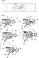
- FIGS. 3 and 4th show schematic representations of an embodiment of a device 2 for hot forming according to the invention.
- Fig. 3 shows the side view, Fig. 4 supervision of the device.
- the device has an inner shaping tool 40 for shaping the inner lateral surfaces and two outer shaping tools 21 for shaping the outer lateral surfaces of the glass tube 30.
- the glass tube 30 rotates, the rotational movement is symbolized by the arrow.
- the outer shaping tools 21 are designed as shaping rollers with a round cross-sectional area and are freely rotatable with the aid of the suspension 61. During the forming process, however, the form rollers 21 are fixed by the locking device 82, so that rotation of the form rollers 21 is not possible. Thus, the forming rollers 21 are not rotated by the rotating glass tube 30, but remain fixed in their position by the device 82. Thus, glass tube 30 and form roller 21 have a relative movement to one another. Since the form rollers 21 are fixed by the detent 82 during the forming process, only a small portion of the outer surface of the form rollers 21 comes into contact with the hot glass tube 30, while the remaining outer surface of the form rollers 21 is not in contact with the glass tube. Thus, only a small part of the outer surface of the form roller 21 serves as a contact surface with the glass tube.
- the device 2 according to the invention also has devices 90 for applying lubricants to the outer form rollers 21.
- the outlet openings of the devices 90 for applying the lubricating oil and the molding tool are arranged at an angular distance of at least 45 ° around the axis of rotation of the workpiece. This arrangement of the device 90 ensures that the lubricant is not applied to the contact surface of the form roller 21 with the hot glass tube 30, but to another, cold area of the form roller 21.
- the device 2 according to the invention also has devices 100 for cooling the shaping rolls. This can prevent thermal decomposition of the lubricant. This leads to less soot formation and thus less contamination of the workpiece.
- Fig. 5 shows a schematic representation of an embodiment of the forming method according to the invention.
- the device 2a corresponds to that in FIGS Figures 3 and 4th Device 2 according to the invention shown.
- a glass workpiece 30 is provided and positioned on the inner mold 40, the workpiece being heated until the glass softens.
- the outer mold 21 is designed as a form roller with a round cross section and rotatably mounted with the suspension 60. With the aid of the locking device 82, the form roller is fixed.
- the workpiece 30 is shaped in step b).
- the workpiece 30 undergoes a rotational movement about its center.
- the rotation movement is symbolized by the arrow.
- the inner lateral surfaces of the workpiece 30 are shaped by the inner mold 40.
- the outer jacket surfaces of the workpiece 30 are shaped by the contact surface 22 of the outer molding tool 21.
- the contact surface 22 is covered with a lubricant during the molding process.
- the workpiece 30 is removed from the device 2a in step c1).
- the locking device 82 is released and the shaping roller 21 is rotated by the predefined angle ⁇ .
- the angle a preferably corresponds to the angle of Contact surface 22.
- the position of the shaping roller 21 is subsequently fixed in step c2) by locking the locking device 82.
- step c) the lubricant is applied by the device 90 to a partial area 91 of the outer surface of the shaping roller 21.
- the lubricant is applied to a partial area 91 of the shaping roller 21, which was not part of the contact surface 22 in the previous step b). This ensures that the partial area 91 is not heated or is no longer heated by the contact with the hot glass 30 when the lubricant is applied.
- a cold shaping surface is understood to mean in particular a shaping surface with a surface temperature lower than 250 ° C.
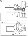
- FIGS. 6 and 7 show schematic representations of an embodiment with a shaping roller 25 with a polygonal cross section.
- the shaping roller shown here has a cross section in the form of a dodecagon.
- 12 shaping surfaces 26 are available as contact surfaces.
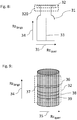
- Fig. 8 shows a schematic representation of a formed glass vial 31.
- the measuring directions for the roughness Rz longitudinal and Rz transverse with respect to the longitudinal axis 33 of the glass vial in the measuring area 32 are represented by the arrows 34 and 35.
- the arrow 34 indicates the axial direction and arrow 35 the tangential direction.
- the measuring range 32 lies in the characteristic surface area 320.
- the exemplary embodiment shown corresponds to the characteristic surface area 320 of the outer surface of the rolled edge.
- the measuring range 32 is shown schematically in Fig. 9 shown.
- the characteristic surface 320 of the glass vial ie the rolled edge, has a plurality of circumferential grooves 36, 37, 38, 39.
- the grooves or grooves 36, 37, 38 and 39 are aligned transversely to the longitudinal axis of the glass vial.
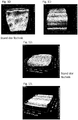
- Fig. 10 the 2D height profile of the surface structure of a characteristic surface area of a glass vial known from the prior art is shown as a comparative example.
- the measuring field has a size of 2 mm x 2 mm and was taken from the area of the rolled edge.
- the 2D height profile is shown in grayscale.
- the abscissa shows the tangential direction and the ordinate the axial direction.
- the pattern embossed during the manufacturing process shows no preferred direction.
- the pattern or the height profile is as pronounced in the circumferential direction, ie in the tangential direction as in the direction of the axis of rotation, ie in the axial direction.
- Fig. 11 shows a 2D height profile of the characteristic surface area of an embodiment.
- the measuring field has a size of 2 mm x 2 mm and was taken from the area of the rolled edge.
- the 2D height profile is shown in grayscale.
- the abscissa shows the tangential direction and the ordinate the axial direction.
- the height profile of the embodiment has an anisotropic distribution. Sections with the same axial value have the same or almost the same heights, while the relief heights of the measuring points with the same tangential values but different axial values differ from one another.
- Fig. 13 shows the 3D height relief of the glass surface of a 2 mm x 2 mm measuring field, shown in grayscale.
- the x-axis shows the tangential direction and the y-axis the axial direction.
- a grinding pattern with grooves or grooves in the tangential direction is shown.
- Fig. 12 3D height profile shown of a characteristic area of the comparative example.
- the comparative example shows no preferred direction in the height profile. Rather, there is no difference here in how the embossed pattern is formed tangentially or axially.
- a total of three measuring areas each of 1 mm x 1 mm were selected and a height relief was created using a white light interferometer of the type Zygo NexView Nx2. The individual measuring areas had a tangential distance of 120 ° to each other and were therefore evenly distributed over the entire circumference of the characteristic surface area.
- the individual measuring areas were aligned in such a way that they were centered in the axial direction in the characteristic surface area.
- the height reliefs were measured and mathematically corrected for the cylindrical shape of the measuring field due to the macroscopic shape of the container.
- the local slope in the tangential direction and in the axial direction was determined from the height reliefs obtained in this way at each point of a height relief.
- the amounts of the corresponding local slope values were averaged over the entire measuring field.
- the corresponding average gradient values of the individual measuring fields were again arithmetically averaged, so that the average tangential gradient or the axial gradient average were determined as the average over the three measuring fields.
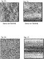
- the Figures 14 and 15 show the slope analyzes in the tangential direction ( Fig. 14 ) and axial direction ( Fig. 15 ) of the comparative example, the local slope values being shown as gray levels.
- the values of the tangential slope and the axial slope hardly differ from one another, ie there is no preferred direction or anisotropy with regard to the distribution of the slopes over the measuring field.
- the values of the slopes also depend on the diameter of the characteristic surfaces, which are always on the outside of the rotationally symmetrical container. The smaller the diameter of the surface area used for the measurement, the greater the gradients that occur. This applies both to the slopes in the tangential and in the axial direction. Table 1 below shows measured values for vials with different rolled edge diameters.
- the slope values shown in Table 1 represent the arithmetic mean values of several samples, the values of the individual samples being determined by arithmetically averaging measurements on three measurement fields in each case on the outer surface of a rolled edge with a measurement field size of 1 mm ⁇ 1 mm.
- the measuring fields were placed centrally in the axial direction.
- the three measuring fields of a measurement were placed at a tangential distance of 120 ° to each other.
- a slope analysis was carried out in both the axial and tangential directions, and the slopes thus obtained were averaged over the respective measuring field by integration.
- the comparative examples were produced using a process known from the prior art with movable outer mold rolls, and the exemplary embodiments were produced using the process according to the invention.
- the exemplary embodiments have an anisotropy with respect to the mean slope values.
- the mean slope values in the tangential direction are significantly lower than in the axial direction. Accordingly, the exemplary embodiments also have significantly lower values for the ratio of the mean tangential gradient to the mean axial gradient than the comparative examples.
Landscapes
- Chemical & Material Sciences (AREA)
- Engineering & Computer Science (AREA)
- Materials Engineering (AREA)
- Organic Chemistry (AREA)
- Health & Medical Sciences (AREA)
- Life Sciences & Earth Sciences (AREA)
- General Health & Medical Sciences (AREA)
- Public Health (AREA)
- Veterinary Medicine (AREA)
- Animal Behavior & Ethology (AREA)
- Hematology (AREA)
- Biomedical Technology (AREA)
- Heart & Thoracic Surgery (AREA)
- Anesthesiology (AREA)
- Vascular Medicine (AREA)
- Ceramic Engineering (AREA)
- Mechanical Engineering (AREA)
- Wood Science & Technology (AREA)
- Pharmacology & Pharmacy (AREA)
- Re-Forming, After-Treatment, Cutting And Transporting Of Glass Products (AREA)
- Medical Preparation Storing Or Oral Administration Devices (AREA)
- Containers Having Bodies Formed In One Piece (AREA)
Applications Claiming Priority (1)
| Application Number | Priority Date | Filing Date | Title |
|---|---|---|---|
| DE102018126053.9A DE102018126053A1 (de) | 2018-10-19 | 2018-10-19 | Verfahren und Vorrichtung zur Heißumformung von gläsernen Werkstücken und heißumgeformte Glasbehälter |
Publications (2)
| Publication Number | Publication Date |
|---|---|
| EP3677554A1 true EP3677554A1 (fr) | 2020-07-08 |
| EP3677554B1 EP3677554B1 (fr) | 2021-12-29 |
Family
ID=67956522
Family Applications (1)
| Application Number | Title | Priority Date | Filing Date |
|---|---|---|---|
| EP19197214.0A Active EP3677554B1 (fr) | 2018-10-19 | 2019-09-13 | Procédé et dispositif de moulage à chaud des pièces en verre et récipients en verre moulés à chaud |
Country Status (5)
| Country | Link |
|---|---|
| US (2) | US11565961B2 (fr) |
| EP (1) | EP3677554B1 (fr) |
| JP (2) | JP7496679B2 (fr) |
| CN (1) | CN111072268B (fr) |
| DE (1) | DE102018126053A1 (fr) |
Cited By (3)
| Publication number | Priority date | Publication date | Assignee | Title |
|---|---|---|---|---|
| JP2020066572A (ja) * | 2018-10-19 | 2020-04-30 | ショット シュヴァイツ アー・ゲーSCHOTT Schweiz AG | ガラス半製品を熱間成形するための方法および装置ならびに熱間成形されたガラス容器 |
| EP4530267A1 (fr) | 2023-09-28 | 2025-04-02 | SCHOTT Pharma AG & Co. KGaA | Outil de formage à chaud pour goulots de bouteille en verre |
| EP4711344A1 (fr) | 2024-09-16 | 2026-03-18 | SCHOTT Pharma AG & Co. KGaA | Outil de formage à chaud pour goulots de bouteille en verre |
Families Citing this family (12)
| Publication number | Priority date | Publication date | Assignee | Title |
|---|---|---|---|---|
| US12454478B2 (en) | 2022-09-09 | 2025-10-28 | Polyplus Battery Company | Ionically conductive glass preform |
| US12294050B2 (en) | 2014-12-02 | 2025-05-06 | Polyplus Battery Company | Lithium ion conducting sulfide glass fabrication |
| US10164289B2 (en) | 2014-12-02 | 2018-12-25 | Polyplus Battery Company | Vitreous solid electrolyte sheets of Li ion conducting sulfur-based glass and associated structures, cells and methods |
| US20190173128A1 (en) | 2014-12-02 | 2019-06-06 | Polyplus Battery Company | Making and inspecting a web of vitreous lithium sulfide separator sheet and lithium electrode assemblies and battery cells |
| HUE052933T2 (hu) * | 2015-04-24 | 2021-05-28 | Nipro Corp | Eljárás gyógyszeres üvegedény elõállítására, valamint egy rotátorral ellátott tûzfúvó eszköz |
| US12482827B2 (en) | 2021-04-13 | 2025-11-25 | Polyplus Battery Company | Binary phosphorus nitride protective solid electrolyte intermediary structures for electrode assemblies |
| DE102020114886A1 (de) * | 2020-06-04 | 2021-12-09 | Gerresheimer Bünde Gmbh | Verfahren und eine Anlage zum Herstellen eines Glaszeuges |
| DE102020114880A1 (de) * | 2020-06-04 | 2021-12-09 | Gerresheimer Bünde Gmbh | Vorrichtung zum Umformen eines Glaszeuges |
| US12021187B2 (en) | 2020-08-04 | 2024-06-25 | Polyplus Battery Company | Surface treatment of a sulfide glass solid electrolyte layer |
| US12034116B2 (en) | 2020-08-04 | 2024-07-09 | Polyplus Battery Company | Glass solid electrolyte layer, methods of making glass solid electrolyte layer and electrodes and battery cells thereof |
| US12021238B2 (en) | 2020-08-04 | 2024-06-25 | Polyplus Battery Company | Glassy embedded solid-state electrode assemblies, solid-state batteries and methods of making electrode assemblies and solid-state batteries |
| CN115650558B (zh) * | 2022-11-11 | 2023-11-21 | 山东景耀玻璃集团有限公司 | 一种轻量玻璃容器快速成型系统及方法 |
Citations (4)
| Publication number | Priority date | Publication date | Assignee | Title |
|---|---|---|---|---|
| DE46337C (de) * | R. MANNESMANN in Remscheid | Verfahren zur Herstellung von Röhren aus Glas und dergl | ||
| DE45584C (de) * | R. MANNESMANN in Remscheid - Bödinghausen | Verfahren zum Aufweiten von Röhren aus Glas und anderen, nicht metallischen, durch Wärme in einen plastischen Zustand versetzbaren Massen | ||
| DE202004004560U1 (de) | 2004-03-17 | 2004-07-15 | Ambeg - Dr. J. Dichter Gmbh | Glasbearbeitungsmaschine |
| WO2018011148A1 (fr) * | 2016-07-12 | 2018-01-18 | Schott Ag | Procédé et dispositif pour mouler une pièce en verre avec une lubrification minimale |
Family Cites Families (37)
| Publication number | Priority date | Publication date | Assignee | Title |
|---|---|---|---|---|
| US1501773A (en) * | 1918-05-07 | 1924-07-15 | Millville Machine Company | Vial-necking machine |
| US1643215A (en) * | 1924-08-07 | 1927-09-20 | Ruth Glass Company | Machine for shaping ends of glass tubes |
| US1914205A (en) * | 1931-06-24 | 1933-06-13 | Gen Electric | Machine and method of shaping silica and the like |
| US1906617A (en) * | 1931-11-09 | 1933-05-02 | Kimble Glass Co | Flat-top screw-threaded vial manufacture |
| US2266417A (en) * | 1939-12-19 | 1941-12-16 | Eisler Charles | Machine for shaping the mouths of tubular glass articles |
| US2446000A (en) * | 1943-11-17 | 1948-07-27 | Eisler Charles | Machine for flanging glass blanks |
| US3171730A (en) * | 1960-09-19 | 1965-03-02 | Owens Illinois Glass Co | Method and apparatus for forming mouth portions of small glass bottles |
| DE1224451B (de) * | 1962-09-18 | 1966-09-08 | Dichter E H Jakob Dr Ing | Maschine zur automatischen Herstellung kleiner Glasflaschen |
| BE646104A (fr) * | 1963-04-05 | |||
| US3343937A (en) * | 1964-04-13 | 1967-09-26 | Owens Illinois Inc | Apparatus for forming the open end portion of small glass containers |
| BE659297A (fr) * | 1965-02-04 | 1965-05-28 | ||
| DE3313851C1 (de) * | 1983-04-16 | 1984-11-22 | Veba-Glas Ag, 4300 Essen | Verfahren zum Einbringen eines Trenn- bzw. Schmiermittels in die Vorform einer IS- oder RIS-Maschine sowie Vorform zur Durchfuehrung dieses Verfahrens |
| JPH0421531A (ja) * | 1990-05-15 | 1992-01-24 | Naigai Glass Kogyo Kk | 瓶口成形装置 |
| DE4028824C1 (fr) * | 1990-09-11 | 1992-03-05 | Schott Glaswerke, 6500 Mainz, De | |
| DE4028823C2 (de) * | 1990-09-11 | 1994-07-07 | Schott Glaswerke | Vorrichtung und Formfinger zum Formen eines Mündungsbereiches an einem Glasfläschchen |
| US6640587B1 (en) * | 2000-09-29 | 2003-11-04 | Lucent Technologies Inc. | Lubricated glass mold |
| US20060267250A1 (en) * | 2005-05-24 | 2006-11-30 | Gerretz Herbert A | Device and method for forming a non-ground vial |
| US7390240B2 (en) * | 2005-10-14 | 2008-06-24 | Air Products And Chemicals, Inc. | Method of shaping and forming work materials |
| DE102008052625A1 (de) | 2008-10-22 | 2010-04-29 | Tesa Se | Thermisch vernetzende Polyacrylate und Verfahren zu deren Herstellung |
| US8173561B2 (en) * | 2009-11-10 | 2012-05-08 | Kennametal Inc. | Inert high hardness material for tool lens production in imaging applications |
| US9227295B2 (en) * | 2011-05-27 | 2016-01-05 | Corning Incorporated | Non-polished glass wafer, thinning system and method for using the non-polished glass wafer to thin a semiconductor wafer |
| JP6159304B2 (ja) * | 2014-09-19 | 2017-07-05 | 大和特殊硝子株式会社 | ガラス容器の製造方法 |
| CN104291558A (zh) * | 2014-09-26 | 2015-01-21 | 江苏惠宇机械制造有限公司 | 一种全自动西林瓶瓶口的成型装置 |
| DE102015002456A1 (de) | 2015-02-23 | 2016-08-25 | Schott Schweiz Ag | Vorrichtung und Verfahren zur Formung von Glaskörpern |
| DE102015111993A1 (de) * | 2015-07-23 | 2017-01-26 | Schott Ag | Formdorn mit Diffusionsschicht zur Glasformung |
| US9422187B1 (en) * | 2015-08-21 | 2016-08-23 | Corning Incorporated | Laser sintering system and method for forming high purity, low roughness silica glass |
| DE102015117422A1 (de) * | 2015-10-13 | 2017-04-13 | Schott Ag | Wolfram-haltiger Formdorn zur Glasformung |
| CN105921519A (zh) | 2016-05-06 | 2016-09-07 | 太原科技大学 | 一种镁合金板材工作辊温度控制方法与装置 |
| DE102016114104A1 (de) * | 2016-07-29 | 2018-02-01 | Schott Ag | Verfahren zur lasergestützen Umformung von Glaskörpern |
| CN110944951B (zh) * | 2017-03-24 | 2022-09-27 | 康宁股份有限公司 | 用于在管转换期间测量玻璃温度的系统及方法 |
| CN107021610A (zh) * | 2017-06-07 | 2017-08-08 | 吴秀兰 | 一直用于热弯玻璃表面平整度的修复工艺 |
| CN116332482A (zh) * | 2017-08-10 | 2023-06-27 | Agc株式会社 | Tft用玻璃基板 |
| US11186513B2 (en) * | 2017-11-30 | 2021-11-30 | Corning Incorporated | Systems and methods for minimizing SHR from pharmaceutical part converting using negative pressure evacuation |
| DE102018126053A1 (de) * | 2018-10-19 | 2020-04-23 | Schott Schweiz Ag | Verfahren und Vorrichtung zur Heißumformung von gläsernen Werkstücken und heißumgeformte Glasbehälter |
| WO2020111282A1 (fr) * | 2018-11-30 | 2020-06-04 | Hoya株式会社 | Procédé de fabrication de plaque de verre, procédé de chanfreinage d'une plaque de verre et procédé de fabrication d'un disque magnétique |
| EP3892593A4 (fr) * | 2018-12-07 | 2022-08-31 | Nipro Corporation | Dispositif de traitement d'un élément en verre |
| EP3889117B1 (fr) * | 2020-04-03 | 2025-06-25 | Schott Ag | Production d'un tube de verre ayant une qualité supérieure |
-
2018
- 2018-10-19 DE DE102018126053.9A patent/DE102018126053A1/de not_active Withdrawn
-
2019
- 2019-09-13 EP EP19197214.0A patent/EP3677554B1/fr active Active
- 2019-10-15 US US16/601,981 patent/US11565961B2/en active Active
- 2019-10-18 CN CN201910994786.6A patent/CN111072268B/zh active Active
- 2019-10-18 JP JP2019190791A patent/JP7496679B2/ja active Active
-
2022
- 2022-12-09 US US18/078,505 patent/US20230106814A1/en active Pending
-
2024
- 2024-03-27 JP JP2024051485A patent/JP7735461B2/ja active Active
Patent Citations (4)
| Publication number | Priority date | Publication date | Assignee | Title |
|---|---|---|---|---|
| DE46337C (de) * | R. MANNESMANN in Remscheid | Verfahren zur Herstellung von Röhren aus Glas und dergl | ||
| DE45584C (de) * | R. MANNESMANN in Remscheid - Bödinghausen | Verfahren zum Aufweiten von Röhren aus Glas und anderen, nicht metallischen, durch Wärme in einen plastischen Zustand versetzbaren Massen | ||
| DE202004004560U1 (de) | 2004-03-17 | 2004-07-15 | Ambeg - Dr. J. Dichter Gmbh | Glasbearbeitungsmaschine |
| WO2018011148A1 (fr) * | 2016-07-12 | 2018-01-18 | Schott Ag | Procédé et dispositif pour mouler une pièce en verre avec une lubrification minimale |
Cited By (4)
| Publication number | Priority date | Publication date | Assignee | Title |
|---|---|---|---|---|
| JP2020066572A (ja) * | 2018-10-19 | 2020-04-30 | ショット シュヴァイツ アー・ゲーSCHOTT Schweiz AG | ガラス半製品を熱間成形するための方法および装置ならびに熱間成形されたガラス容器 |
| EP4530267A1 (fr) | 2023-09-28 | 2025-04-02 | SCHOTT Pharma AG & Co. KGaA | Outil de formage à chaud pour goulots de bouteille en verre |
| EP4530266A1 (fr) | 2023-09-28 | 2025-04-02 | SCHOTT Pharma AG & Co. KGaA | Outil de formage à chaud pour goulots de bouteille en verre |
| EP4711344A1 (fr) | 2024-09-16 | 2026-03-18 | SCHOTT Pharma AG & Co. KGaA | Outil de formage à chaud pour goulots de bouteille en verre |
Also Published As
| Publication number | Publication date |
|---|---|
| JP2020066572A (ja) | 2020-04-30 |
| EP3677554B1 (fr) | 2021-12-29 |
| DE102018126053A1 (de) | 2020-04-23 |
| JP2024075764A (ja) | 2024-06-04 |
| JP7496679B2 (ja) | 2024-06-07 |
| US11565961B2 (en) | 2023-01-31 |
| CN111072268A (zh) | 2020-04-28 |
| US20200123038A1 (en) | 2020-04-23 |
| US20230106814A1 (en) | 2023-04-06 |
| CN111072268B (zh) | 2023-07-04 |
| JP7735461B2 (ja) | 2025-09-08 |
Similar Documents
| Publication | Publication Date | Title |
|---|---|---|
| EP3677554B1 (fr) | Procédé et dispositif de moulage à chaud des pièces en verre et récipients en verre moulés à chaud | |
| EP3049200B1 (fr) | Procédé de forgeage à chaud d'un corps creux sans soudure en matériau difficile à déformer | |
| DE102012017525B4 (de) | Verfahren zur umformenden Herstellung eines Zahnrads mit Außenverzahnung, sowie nach diesem Verfahren herstellbares Zahnrad mit Außenverzahnung | |
| WO2013131720A1 (fr) | Outil de moulage, procédé et dispositif de façonnage de verre assisté par laser | |
| EP3484826B1 (fr) | Procédé et dispositif pour mouler une pièce en verre avec une lubrification minimale | |
| EP0882532B1 (fr) | Dispositif de fluotournage et procédé pour la fabrication de pièces à denture plate | |
| DE10134198B4 (de) | Verfahren zum Herstellen von Glaskugeln | |
| EP3717434B1 (fr) | Procédé de fabrication d'un article en verre | |
| DE102009024847B4 (de) | Vorrichtung zur Herstellung wendelförmiger Wellrohre | |
| EP3652120B1 (fr) | Outil de façonnage à chaud par enlèvement de matière utilisé pour produire des contenants en verre | |
| DE102017011991A1 (de) | Verfahren und Vorrichtung zur Herstellung von Glasprodukten | |
| EP3010667B1 (fr) | Procédé et dispositif permettant de produire des éléments métalliques à symétrie de rotation | |
| DE102011013623B4 (de) | Verfahren zur Herstellung einer für die Fertigung von Ampullen und Fläschchen geeigneten Glasröhre und Vorrichtung zur Herstellung | |
| EP3054018B1 (fr) | Dispositif de chargement pour le traitement thermique indéformable de pièces usinées | |
| EP1444901B1 (fr) | Procédé et dispositif pour produire des corps creux en forme de coquilles à partir d'une masse de confiserie | |
| DE803923C (de) | Verfahren zum Giessen von Glasgegenstaenden | |
| WO2000063568A2 (fr) | Procede et dispositif permettant de realiser des pieces externes de joint homocinetique, ayant subi un formage plastique | |
| DE3942566C2 (fr) | ||
| DE920888C (de) | Verfahren und Fuellstueck zum Erzeugen von Ringnuten in Waelzlagerringen | |
| EP3497253B1 (fr) | Dispositif de chargement pour le traitement thermique de pièces avec stabilité de forme | |
| DE102016204994B4 (de) | Querwalzverfahren, Vorrichtung zur Durchführung des Verfahrens sowie damit hergestelltes Bauteil | |
| DE102011056900B4 (de) | Verfahren und Anordnung zur Herstellung von spanend bearbeiteten Werkstücken | |
| DE1300641B (de) | Verfahren und Formwerkzeug zum Formen von Rotationskoerpern aus Glas | |
| DE2547218A1 (de) | Verfahren zum herstellen eines selbstsichernden scharnierstiftes und nach diesem verfahren hergestellter scharnierstift | |
| EP0219019A2 (fr) | Installation pour le laminage transversal plastique d'ébauches métalliques frittées poreuses à symétrie de rotation |
Legal Events
| Date | Code | Title | Description |
|---|---|---|---|
| PUAI | Public reference made under article 153(3) epc to a published international application that has entered the european phase |
Free format text: ORIGINAL CODE: 0009012 |
|
| STAA | Information on the status of an ep patent application or granted ep patent |
Free format text: STATUS: THE APPLICATION HAS BEEN PUBLISHED |
|
| AK | Designated contracting states |
Kind code of ref document: A1 Designated state(s): AL AT BE BG CH CY CZ DE DK EE ES FI FR GB GR HR HU IE IS IT LI LT LU LV MC MK MT NL NO PL PT RO RS SE SI SK SM TR |
|
| AX | Request for extension of the european patent |
Extension state: BA ME |
|
| STAA | Information on the status of an ep patent application or granted ep patent |
Free format text: STATUS: REQUEST FOR EXAMINATION WAS MADE |
|
| 17P | Request for examination filed |
Effective date: 20201208 |
|
| RBV | Designated contracting states (corrected) |
Designated state(s): AL AT BE BG CH CY CZ DE DK EE ES FI FR GB GR HR HU IE IS IT LI LT LU LV MC MK MT NL NO PL PT RO RS SE SI SK SM TR |
|
| GRAP | Despatch of communication of intention to grant a patent |
Free format text: ORIGINAL CODE: EPIDOSNIGR1 |
|
| STAA | Information on the status of an ep patent application or granted ep patent |
Free format text: STATUS: GRANT OF PATENT IS INTENDED |
|
| INTG | Intention to grant announced |
Effective date: 20210503 |
|
| GRAJ | Information related to disapproval of communication of intention to grant by the applicant or resumption of examination proceedings by the epo deleted |
Free format text: ORIGINAL CODE: EPIDOSDIGR1 |
|
| STAA | Information on the status of an ep patent application or granted ep patent |
Free format text: STATUS: REQUEST FOR EXAMINATION WAS MADE |
|
| GRAS | Grant fee paid |
Free format text: ORIGINAL CODE: EPIDOSNIGR3 |
|
| STAA | Information on the status of an ep patent application or granted ep patent |
Free format text: STATUS: GRANT OF PATENT IS INTENDED |
|
| GRAP | Despatch of communication of intention to grant a patent |
Free format text: ORIGINAL CODE: EPIDOSNIGR1 |
|
| INTC | Intention to grant announced (deleted) | ||
| INTG | Intention to grant announced |
Effective date: 20210924 |
|
| GRAA | (expected) grant |
Free format text: ORIGINAL CODE: 0009210 |
|
| STAA | Information on the status of an ep patent application or granted ep patent |
Free format text: STATUS: THE PATENT HAS BEEN GRANTED |
|
| AK | Designated contracting states |
Kind code of ref document: B1 Designated state(s): AL AT BE BG CH CY CZ DE DK EE ES FI FR GB GR HR HU IE IS IT LI LT LU LV MC MK MT NL NO PL PT RO RS SE SI SK SM TR |
|
| REG | Reference to a national code |
Ref country code: GB Ref legal event code: FG4D Free format text: NOT ENGLISH |
|
| REG | Reference to a national code |
Ref country code: CH Ref legal event code: EP |
|
| REG | Reference to a national code |
Ref country code: AT Ref legal event code: REF Ref document number: 1458566 Country of ref document: AT Kind code of ref document: T Effective date: 20220115 |
|
| REG | Reference to a national code |
Ref country code: IE Ref legal event code: FG4D Free format text: LANGUAGE OF EP DOCUMENT: GERMAN |
|
| REG | Reference to a national code |
Ref country code: DE Ref legal event code: R096 Ref document number: 502019003096 Country of ref document: DE |
|
| REG | Reference to a national code |
Ref country code: LT Ref legal event code: MG9D |
|
| PG25 | Lapsed in a contracting state [announced via postgrant information from national office to epo] |
Ref country code: RS Free format text: LAPSE BECAUSE OF FAILURE TO SUBMIT A TRANSLATION OF THE DESCRIPTION OR TO PAY THE FEE WITHIN THE PRESCRIBED TIME-LIMIT Effective date: 20211229 Ref country code: LT Free format text: LAPSE BECAUSE OF FAILURE TO SUBMIT A TRANSLATION OF THE DESCRIPTION OR TO PAY THE FEE WITHIN THE PRESCRIBED TIME-LIMIT Effective date: 20211229 Ref country code: FI Free format text: LAPSE BECAUSE OF FAILURE TO SUBMIT A TRANSLATION OF THE DESCRIPTION OR TO PAY THE FEE WITHIN THE PRESCRIBED TIME-LIMIT Effective date: 20211229 Ref country code: BG Free format text: LAPSE BECAUSE OF FAILURE TO SUBMIT A TRANSLATION OF THE DESCRIPTION OR TO PAY THE FEE WITHIN THE PRESCRIBED TIME-LIMIT Effective date: 20220329 |
|
| REG | Reference to a national code |
Ref country code: NL Ref legal event code: MP Effective date: 20211229 |
|
| PG25 | Lapsed in a contracting state [announced via postgrant information from national office to epo] |
Ref country code: SE Free format text: LAPSE BECAUSE OF FAILURE TO SUBMIT A TRANSLATION OF THE DESCRIPTION OR TO PAY THE FEE WITHIN THE PRESCRIBED TIME-LIMIT Effective date: 20211229 Ref country code: NO Free format text: LAPSE BECAUSE OF FAILURE TO SUBMIT A TRANSLATION OF THE DESCRIPTION OR TO PAY THE FEE WITHIN THE PRESCRIBED TIME-LIMIT Effective date: 20220329 Ref country code: LV Free format text: LAPSE BECAUSE OF FAILURE TO SUBMIT A TRANSLATION OF THE DESCRIPTION OR TO PAY THE FEE WITHIN THE PRESCRIBED TIME-LIMIT Effective date: 20211229 Ref country code: HR Free format text: LAPSE BECAUSE OF FAILURE TO SUBMIT A TRANSLATION OF THE DESCRIPTION OR TO PAY THE FEE WITHIN THE PRESCRIBED TIME-LIMIT Effective date: 20211229 Ref country code: GR Free format text: LAPSE BECAUSE OF FAILURE TO SUBMIT A TRANSLATION OF THE DESCRIPTION OR TO PAY THE FEE WITHIN THE PRESCRIBED TIME-LIMIT Effective date: 20220330 |
|
| PG25 | Lapsed in a contracting state [announced via postgrant information from national office to epo] |
Ref country code: NL Free format text: LAPSE BECAUSE OF FAILURE TO SUBMIT A TRANSLATION OF THE DESCRIPTION OR TO PAY THE FEE WITHIN THE PRESCRIBED TIME-LIMIT Effective date: 20211229 |
|
| PG25 | Lapsed in a contracting state [announced via postgrant information from national office to epo] |
Ref country code: SM Free format text: LAPSE BECAUSE OF FAILURE TO SUBMIT A TRANSLATION OF THE DESCRIPTION OR TO PAY THE FEE WITHIN THE PRESCRIBED TIME-LIMIT Effective date: 20211229 Ref country code: SK Free format text: LAPSE BECAUSE OF FAILURE TO SUBMIT A TRANSLATION OF THE DESCRIPTION OR TO PAY THE FEE WITHIN THE PRESCRIBED TIME-LIMIT Effective date: 20211229 Ref country code: RO Free format text: LAPSE BECAUSE OF FAILURE TO SUBMIT A TRANSLATION OF THE DESCRIPTION OR TO PAY THE FEE WITHIN THE PRESCRIBED TIME-LIMIT Effective date: 20211229 Ref country code: PT Free format text: LAPSE BECAUSE OF FAILURE TO SUBMIT A TRANSLATION OF THE DESCRIPTION OR TO PAY THE FEE WITHIN THE PRESCRIBED TIME-LIMIT Effective date: 20220429 Ref country code: ES Free format text: LAPSE BECAUSE OF FAILURE TO SUBMIT A TRANSLATION OF THE DESCRIPTION OR TO PAY THE FEE WITHIN THE PRESCRIBED TIME-LIMIT Effective date: 20211229 Ref country code: EE Free format text: LAPSE BECAUSE OF FAILURE TO SUBMIT A TRANSLATION OF THE DESCRIPTION OR TO PAY THE FEE WITHIN THE PRESCRIBED TIME-LIMIT Effective date: 20211229 Ref country code: CZ Free format text: LAPSE BECAUSE OF FAILURE TO SUBMIT A TRANSLATION OF THE DESCRIPTION OR TO PAY THE FEE WITHIN THE PRESCRIBED TIME-LIMIT Effective date: 20211229 |
|
| PG25 | Lapsed in a contracting state [announced via postgrant information from national office to epo] |
Ref country code: PL Free format text: LAPSE BECAUSE OF FAILURE TO SUBMIT A TRANSLATION OF THE DESCRIPTION OR TO PAY THE FEE WITHIN THE PRESCRIBED TIME-LIMIT Effective date: 20211229 |
|
| PG25 | Lapsed in a contracting state [announced via postgrant information from national office to epo] |
Ref country code: IS Free format text: LAPSE BECAUSE OF FAILURE TO SUBMIT A TRANSLATION OF THE DESCRIPTION OR TO PAY THE FEE WITHIN THE PRESCRIBED TIME-LIMIT Effective date: 20220429 |
|
| REG | Reference to a national code |
Ref country code: DE Ref legal event code: R097 Ref document number: 502019003096 Country of ref document: DE |
|
| PG25 | Lapsed in a contracting state [announced via postgrant information from national office to epo] |
Ref country code: DK Free format text: LAPSE BECAUSE OF FAILURE TO SUBMIT A TRANSLATION OF THE DESCRIPTION OR TO PAY THE FEE WITHIN THE PRESCRIBED TIME-LIMIT Effective date: 20211229 Ref country code: AL Free format text: LAPSE BECAUSE OF FAILURE TO SUBMIT A TRANSLATION OF THE DESCRIPTION OR TO PAY THE FEE WITHIN THE PRESCRIBED TIME-LIMIT Effective date: 20211229 |
|
| PLBE | No opposition filed within time limit |
Free format text: ORIGINAL CODE: 0009261 |
|
| STAA | Information on the status of an ep patent application or granted ep patent |
Free format text: STATUS: NO OPPOSITION FILED WITHIN TIME LIMIT |
|
| 26N | No opposition filed |
Effective date: 20220930 |
|
| REG | Reference to a national code |
Ref country code: BE Ref legal event code: PD Owner name: SCHOTT PHARMA SCHWEIZ AG; CH Free format text: DETAILS ASSIGNMENT: CHANGE OF OWNER(S), MERGE; FORMER OWNER NAME: SCHOTT PHARMA SCHWEIZ AG Effective date: 20221222 |
|
| PG25 | Lapsed in a contracting state [announced via postgrant information from national office to epo] |
Ref country code: SI Free format text: LAPSE BECAUSE OF FAILURE TO SUBMIT A TRANSLATION OF THE DESCRIPTION OR TO PAY THE FEE WITHIN THE PRESCRIBED TIME-LIMIT Effective date: 20211229 |
|
| REG | Reference to a national code |
Ref country code: DE Ref legal event code: R081 Ref document number: 502019003096 Country of ref document: DE Owner name: SCHOTT PHARMA SCHWEIZ AG, CH Free format text: FORMER OWNER: SCHOTT SCHWEIZ AG, ST. GALLEN, CH |
|
| PG25 | Lapsed in a contracting state [announced via postgrant information from national office to epo] |
Ref country code: MC Free format text: LAPSE BECAUSE OF FAILURE TO SUBMIT A TRANSLATION OF THE DESCRIPTION OR TO PAY THE FEE WITHIN THE PRESCRIBED TIME-LIMIT Effective date: 20211229 |
|
| P01 | Opt-out of the competence of the unified patent court (upc) registered |
Effective date: 20230512 |
|
| PG25 | Lapsed in a contracting state [announced via postgrant information from national office to epo] |
Ref country code: LU Free format text: LAPSE BECAUSE OF NON-PAYMENT OF DUE FEES Effective date: 20220913 |
|
| PG25 | Lapsed in a contracting state [announced via postgrant information from national office to epo] |
Ref country code: IE Free format text: LAPSE BECAUSE OF NON-PAYMENT OF DUE FEES Effective date: 20220913 |
|
| PG25 | Lapsed in a contracting state [announced via postgrant information from national office to epo] |
Ref country code: CY Free format text: LAPSE BECAUSE OF FAILURE TO SUBMIT A TRANSLATION OF THE DESCRIPTION OR TO PAY THE FEE WITHIN THE PRESCRIBED TIME-LIMIT Effective date: 20211229 |
|
| PG25 | Lapsed in a contracting state [announced via postgrant information from national office to epo] |
Ref country code: MK Free format text: LAPSE BECAUSE OF FAILURE TO SUBMIT A TRANSLATION OF THE DESCRIPTION OR TO PAY THE FEE WITHIN THE PRESCRIBED TIME-LIMIT Effective date: 20211229 Ref country code: HU Free format text: LAPSE BECAUSE OF FAILURE TO SUBMIT A TRANSLATION OF THE DESCRIPTION OR TO PAY THE FEE WITHIN THE PRESCRIBED TIME-LIMIT; INVALID AB INITIO Effective date: 20190913 |
|
| PG25 | Lapsed in a contracting state [announced via postgrant information from national office to epo] |
Ref country code: MT Free format text: LAPSE BECAUSE OF FAILURE TO SUBMIT A TRANSLATION OF THE DESCRIPTION OR TO PAY THE FEE WITHIN THE PRESCRIBED TIME-LIMIT Effective date: 20211229 |
|
| REG | Reference to a national code |
Ref country code: CH Ref legal event code: U11 Free format text: ST27 STATUS EVENT CODE: U-0-0-U10-U11 (AS PROVIDED BY THE NATIONAL OFFICE) Effective date: 20251001 |
|
| PGFP | Annual fee paid to national office [announced via postgrant information from national office to epo] |
Ref country code: DE Payment date: 20250919 Year of fee payment: 7 |
|
| PGFP | Annual fee paid to national office [announced via postgrant information from national office to epo] |
Ref country code: IT Payment date: 20250923 Year of fee payment: 7 |
|
| PGFP | Annual fee paid to national office [announced via postgrant information from national office to epo] |
Ref country code: BE Payment date: 20250918 Year of fee payment: 7 Ref country code: GB Payment date: 20250919 Year of fee payment: 7 |
|
| PGFP | Annual fee paid to national office [announced via postgrant information from national office to epo] |
Ref country code: FR Payment date: 20250922 Year of fee payment: 7 |
|
| REG | Reference to a national code |
Ref country code: AT Ref legal event code: MM01 Ref document number: 1458566 Country of ref document: AT Kind code of ref document: T Effective date: 20240913 |
|
| PG25 | Lapsed in a contracting state [announced via postgrant information from national office to epo] |
Ref country code: TR Free format text: LAPSE BECAUSE OF FAILURE TO SUBMIT A TRANSLATION OF THE DESCRIPTION OR TO PAY THE FEE WITHIN THE PRESCRIBED TIME-LIMIT Effective date: 20211229 |
|
| PG25 | Lapsed in a contracting state [announced via postgrant information from national office to epo] |
Ref country code: AT Free format text: LAPSE BECAUSE OF NON-PAYMENT OF DUE FEES Effective date: 20240913 |
|
| PGFP | Annual fee paid to national office [announced via postgrant information from national office to epo] |
Ref country code: CH Payment date: 20251001 Year of fee payment: 7 |
|
| PGFP | Annual fee paid to national office [announced via postgrant information from national office to epo] |
Ref country code: AT Payment date: 20260410 Year of fee payment: 5 |