EP3678214B1 - Construction, bloc d'accumulateur et système de travaux de jardinage et / ou forestiers - Google Patents
Construction, bloc d'accumulateur et système de travaux de jardinage et / ou forestiers Download PDFInfo
- Publication number
- EP3678214B1 EP3678214B1 EP19150504.9A EP19150504A EP3678214B1 EP 3678214 B1 EP3678214 B1 EP 3678214B1 EP 19150504 A EP19150504 A EP 19150504A EP 3678214 B1 EP3678214 B1 EP 3678214B1
- Authority
- EP
- European Patent Office
- Prior art keywords
- cable
- head
- sensor
- cell
- securing
- Prior art date
- Legal status (The legal status is an assumption and is not a legal conclusion. Google has not performed a legal analysis and makes no representation as to the accuracy of the status listed.)
- Active
Links
Images



Classifications
-
- G—PHYSICS
- G01—MEASURING; TESTING
- G01K—MEASURING TEMPERATURE; MEASURING QUANTITY OF HEAT; THERMALLY-SENSITIVE ELEMENTS NOT OTHERWISE PROVIDED FOR
- G01K7/00—Measuring temperature based on the use of electric or magnetic elements directly sensitive to heat ; Power supply therefor, e.g. using thermoelectric elements
- G01K7/16—Measuring temperature based on the use of electric or magnetic elements directly sensitive to heat ; Power supply therefor, e.g. using thermoelectric elements using resistive elements
- G01K7/22—Measuring temperature based on the use of electric or magnetic elements directly sensitive to heat ; Power supply therefor, e.g. using thermoelectric elements using resistive elements the element being a non-linear resistance, e.g. thermistor
-
- A—HUMAN NECESSITIES
- A01—AGRICULTURE; FORESTRY; ANIMAL HUSBANDRY; HUNTING; TRAPPING; FISHING
- A01D—HARVESTING; MOWING
- A01D34/00—Mowers; Mowing apparatus of harvesters
- A01D34/01—Mowers; Mowing apparatus of harvesters characterised by features relating to the type of cutting apparatus
- A01D34/412—Mowers; Mowing apparatus of harvesters characterised by features relating to the type of cutting apparatus having rotating cutters
- A01D34/63—Mowers; Mowing apparatus of harvesters characterised by features relating to the type of cutting apparatus having rotating cutters having cutters rotating about a vertical axis
- A01D34/76—Driving mechanisms for the cutters
- A01D34/78—Driving mechanisms for the cutters electric
-
- A—HUMAN NECESSITIES
- A01—AGRICULTURE; FORESTRY; ANIMAL HUSBANDRY; HUNTING; TRAPPING; FISHING
- A01G—HORTICULTURE; CULTIVATION OF VEGETABLES, FLOWERS, RICE, FRUIT, VINES, HOPS OR SEAWEED; FORESTRY; WATERING
- A01G23/00—Forestry
-
- G—PHYSICS
- G01—MEASURING; TESTING
- G01K—MEASURING TEMPERATURE; MEASURING QUANTITY OF HEAT; THERMALLY-SENSITIVE ELEMENTS NOT OTHERWISE PROVIDED FOR
- G01K1/00—Details of thermometers not specially adapted for particular types of thermometer
- G01K1/02—Means for indicating or recording specially adapted for thermometers
- G01K1/026—Means for indicating or recording specially adapted for thermometers arrangements for monitoring a plurality of temperatures, e.g. by multiplexing
-
- G—PHYSICS
- G01—MEASURING; TESTING
- G01K—MEASURING TEMPERATURE; MEASURING QUANTITY OF HEAT; THERMALLY-SENSITIVE ELEMENTS NOT OTHERWISE PROVIDED FOR
- G01K1/00—Details of thermometers not specially adapted for particular types of thermometer
- G01K1/14—Supports; Fastening devices; Arrangements for mounting thermometers in particular locations
-
- H—ELECTRICITY
- H01—ELECTRIC ELEMENTS
- H01M—PROCESSES OR MEANS, e.g. BATTERIES, FOR THE DIRECT CONVERSION OF CHEMICAL ENERGY INTO ELECTRICAL ENERGY
- H01M10/00—Secondary cells; Manufacture thereof
- H01M10/42—Methods or arrangements for servicing or maintenance of secondary cells or secondary half-cells
- H01M10/48—Accumulators combined with arrangements for measuring, testing or indicating the condition of cells, e.g. the level or density of the electrolyte
- H01M10/486—Accumulators combined with arrangements for measuring, testing or indicating the condition of cells, e.g. the level or density of the electrolyte for measuring temperature
-
- A—HUMAN NECESSITIES
- A01—AGRICULTURE; FORESTRY; ANIMAL HUSBANDRY; HUNTING; TRAPPING; FISHING
- A01D—HARVESTING; MOWING
- A01D2101/00—Lawn-mowers
-
- H—ELECTRICITY
- H01—ELECTRIC ELEMENTS
- H01M—PROCESSES OR MEANS, e.g. BATTERIES, FOR THE DIRECT CONVERSION OF CHEMICAL ENERGY INTO ELECTRICAL ENERGY
- H01M10/00—Secondary cells; Manufacture thereof
- H01M10/42—Methods or arrangements for servicing or maintenance of secondary cells or secondary half-cells
- H01M10/48—Accumulators combined with arrangements for measuring, testing or indicating the condition of cells, e.g. the level or density of the electrolyte
- H01M10/482—Accumulators combined with arrangements for measuring, testing or indicating the condition of cells, e.g. the level or density of the electrolyte for several batteries or cells simultaneously or sequentially
-
- H—ELECTRICITY
- H01—ELECTRIC ELEMENTS
- H01M—PROCESSES OR MEANS, e.g. BATTERIES, FOR THE DIRECT CONVERSION OF CHEMICAL ENERGY INTO ELECTRICAL ENERGY
- H01M2220/00—Batteries for particular applications
- H01M2220/30—Batteries in portable systems, e.g. mobile phone, laptop
-
- H—ELECTRICITY
- H01—ELECTRIC ELEMENTS
- H01M—PROCESSES OR MEANS, e.g. BATTERIES, FOR THE DIRECT CONVERSION OF CHEMICAL ENERGY INTO ELECTRICAL ENERGY
- H01M50/00—Constructional details or processes of manufacture of the non-active parts of electrochemical cells other than fuel cells, e.g. hybrid cells
- H01M50/20—Mountings; Secondary casings or frames; Racks, modules or packs; Suspension devices; Shock absorbers; Transport or carrying devices; Holders
- H01M50/204—Racks, modules or packs for multiple batteries or multiple cells
- H01M50/207—Racks, modules or packs for multiple batteries or multiple cells characterised by their shape
- H01M50/213—Racks, modules or packs for multiple batteries or multiple cells characterised by their shape adapted for cells having curved cross-section, e.g. round or elliptic
-
- Y—GENERAL TAGGING OF NEW TECHNOLOGICAL DEVELOPMENTS; GENERAL TAGGING OF CROSS-SECTIONAL TECHNOLOGIES SPANNING OVER SEVERAL SECTIONS OF THE IPC; TECHNICAL SUBJECTS COVERED BY FORMER USPC CROSS-REFERENCE ART COLLECTIONS [XRACs] AND DIGESTS
- Y02—TECHNOLOGIES OR APPLICATIONS FOR MITIGATION OR ADAPTATION AGAINST CLIMATE CHANGE
- Y02E—REDUCTION OF GREENHOUSE GAS [GHG] EMISSIONS, RELATED TO ENERGY GENERATION, TRANSMISSION OR DISTRIBUTION
- Y02E60/00—Enabling technologies; Technologies with a potential or indirect contribution to GHG emissions mitigation
- Y02E60/10—Energy storage using batteries
Definitions
- the US 2018/0364108 A1 discloses a temperature sensor including a sensor main body having a contact surface for contacting the surface of a battery cell, a mounting member that holds the sensor main body and fixes it to the battery cell, and a coil spring disposed between the sensor main body and the mounting member.
- the center P1 of the contact surface coincides with the center P2 of a trajectory connecting a pressure point pressed by the coil spring.
- the temperature sensor can absorb all inclinations by the coil spring, and prevent the contact surface from leading away from the surface of the battery cell.
- the object of the invention is to provide a structure for a battery pack for supplying an electrically driven gardening and/or forestry processing device with electrical drive power, wherein the structure enables good, in particular simple, assembly, of a battery pack comprising such a structure and at least one battery cell and of a gardening and/or forestry processing system comprising such a battery pack and an electrically driven gardening and/or forestry processing device.
- the invention solves this problem by providing a structure with the features of claim 1, a battery pack with the features of claim 12 and a gardening and/or forestry system with the features of claim 14.
- Advantageous developments of the invention are described in the dependent claims.
- the structure according to the invention is designed or configured for a battery pack for supplying an electrically driven garden and/or forestry device with electrical drive power.
- the structure has at least one temperature sensor, at least one arrangement body, in particular a receiving body and/or pre-assembly body, and, in particular, at least one cell holder element.
- the temperature sensor has, in particular, only one sensor head and, in particular, only a number, in particular a plurality, of sensor cables that are connected to the sensor head, in particular directly, and in particular mechanically and/or electrically connected.
- the sensor head has, in particular, only one sensor element for, in particular, automatically measuring a temperature, in particular a temperature value, of at least one battery cell.
- the arrangement body defines or has, in particular, only one head arrangement region, in particular a head receiving region, for, in particular, direct and/or spatial arrangement, in particular receiving, in particular only, the sensor head. Furthermore, the arrangement body defines or has, in particular only, a cable arrangement region, in particular a cable receiving region, adjoining the head arrangement region for, in particular, the direct and/or spatial arrangement, in particular the receiving, in particular only, of a cable section of the number of sensor cables. In addition, the arrangement body has at least one head securing element with a cable passage.
- a passage width, in particular a value of the passage width, of the cable passage is greater than or equal to a cable width, in particular a value of the cable width, of the cable section arranged in particular in the cable arrangement region, and smaller than a head width, in particular a value of the head width, of the sensor head arranged in particular in the head arrangement region, such that the at least one head securing element is designed or configured for, in particular, the direct, positive securing of the sensor head arranged in the head arrangement region against movement in, in particular a straight, direction of the cable arrangement region.
- the arrangement body has at least one cable securing element.
- the cable arrangement region can adjoin the head arrangement region in the direction.
- the head arrangement region can be, in particular completely, on an underside of the arrangement body, in particular of the at least one head securing element, and/or the cable arrangement region can be, in particular at least partially or even completely, in the head securing element and/or on an upper side of the arrangement body, in particular of the at least one head securing element, opposite or facing away from the underside.
- the at least one head securing element can partially define or have the head arrangement region and/or the cable arrangement region.
- the cell holder element is designed or configured for, in particular, immediate, positive securing of the sensor head arranged in the head arrangement area against movement out of the head arrangement area, in particular out, during or after mechanical connection of the cell holder element and the arrangement body with the, in particular arranged and secured or pre-assembled, temperature sensor.
- This enables additional security.
- the arrangement body and the temperature sensor can or do not need to be designed for arrangement during or after mechanical connection of the cell holder element and the arrangement body, in particular without a temperature sensor.
- the arrangement body has a cable insertion opening, in particular on a, in particular radial, circumferential side of the arrangement body, for inserting the cable section into the cable arrangement area and/or the cable passage, in particular into it, in particular in the, in particular other, radial direction.
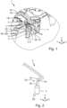
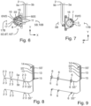
- the arrangement body 6 has at least one peripheral wall 16, as in Fig.1 , 3 to 7 and 11 shown.
- a cable opening width 17B of the cable entry opening 17 and a cable arrangement depth 8T, 10T of the cable arrangement region 8 and/or the cable passage 10 are smaller than the cable width 5B and greater than or equal to a cable thickness 5D of the cable section 5S such that the cable section 5S is arranged, in particular at right angles, rotated relative to the introduction, in particular in the cable arrangement region 8 and/or the cable passage 10, in particular together with the sensor head 3.
- the arrangement body 6 is formed in one piece, as in Fig. 3 shown.
- the mechanical connection of the cell holder element 12 and the arrangement body 6 with the temperature sensor 2 can be carried out as follows, as shown in Fig.1 , 10 and 11 shown.
- the arrangement body 6 with the temperature sensor 2 is introduced into the cell holder element, in particular against the direction z, in particular until the peripheral wall 16 and the cell holder element 12a touch each other.
- the cell holder element 12a and the arrangement body 6 with the temperature sensor 2 are thus mechanically connected to each other.
- the arrangement body 6 is thus secured.
- the temperature sensor 2, in particular the sensor head 3, is thus secured, in particular position-secured.
- the sensor head 3 is secured against movement against the direction z by the cell holder element 12.
- the cell holder element 12a holds the plurality of cell groups 114aG1, 114aG2, 114aG3, 114aG4, 114aG5, 114bG1, 114bG2, 114bG3, 114bG4, 114bG5, 114cG1, 114cG2, 114cG3, 114cG4, 114cG5 on the cell side, in particular the cell peripheral side ZUS.
- The, in particular at least one, sensor element 4 is for measuring the temperature T of two of the plurality of cell groups 114aG1, 114aG2, 114aG3, 114aG4, 114aG5, 114bG1, 114bG2, 114bG3, 114bG4, 114bG5, 114cG1, 114cG2, 114cG3, 114cG4, 114cG5 with mechanical connection of the cell holder element 12a and the, in particular at least one, arrangement body 6 with the, in particular at least one, temperature sensor 2, in particular when holding the plurality of cell groups 114aG1, 114aG2, 114aG3, 114aG4, 114aG5, 114bG1, 114bG2, 114bG3, 114bG4, 114bG5, 114cG1, 114cG2, 114cG3, 114cG4, 114cG5.
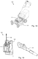
- Fig. 12 to 19 show a battery pack 111 according to the invention for supplying the electrically driven garden and/or forestry device 101 with electrical drive power AL.
- the battery pack 111 has the structure 1 and the at least one battery cell 114a, 114b, 114c, in the embodiment shown, the plurality of accumulator cells 114a, 114b, 114c.
- the measuring electronics part 115 has at least one further connector for electrical connection, in particular with the at least one connector 14.
- the, in particular at least one, sensor head 3, in particular the, in particular at least one, sensor element 4, is thermally connected and cast with the at least one accumulator cell 114a, 114b, 114c, in the embodiment shown the plurality of accumulator cells 114a, 114b, 114c, by means of a thermally conductive adhesive, in particular during or after arrangement on the arrangement body 6, in particular head arrangement region 7, and mechanical connection to the cell holder element 12a.
- the measuring electronics part 115 is designed for electrical connection to the accumulator cells 114a, 114b, 114c by means of the cell connectors 19 and the at least one fuse unit 18a, in particular a cable harness, in particular a medium-voltage tap cable harness, for, in particular, automatic, measurement of voltages, in particular medium voltages, in particular voltage values, of the accumulator cells 114a, 114b, 114c.
- the measuring electronics part 115 is electrically connected to the accumulator cells 114a, 114b, 114c by means of the cell connectors 19 and the at least one fuse unit 18a, in particular a cable harness, in particular a medium-voltage tap cable harness.
- a maximum electrical drive power MAL in particular of the battery pack 111, is a minimum of 50 watts (W) and/or a maximum of 5 kilowatts (kW).
- a maximum energy content MEI in particular of the battery pack 111, is a minimum of 80 watt hours (Wh) and/or a maximum of 5 kilowatt hours (kWh), in particular 1.5 kWh.
- the power lines 117 are mounted on, in particular in, the at least one cell holder element 12a, 12b or laid over the at least one cell holder element 12a, 12b, as in Fig. 16 shown.
- the battery pack 111 has connectors 121, in particular for electrically connecting the battery pack 111 to the garden and/or forestry device 101, as in Fig. 14 to 16 shown.
- the battery pack 111 has a common housing 122, in particular a protective housing, as in Fig. 17 to 19 shown.
- the structure 1 and the accumulator cells 114a, 114c, 114c are arranged in the common housing 122, in particular spatially.
- the measuring electronics part 115, the power electronics part 116, the power lines 117 and the plug connectors 121 are arranged, in particular spatially, in the common housing 122.
- Fig. 18 and 19 show a garden and/or forestry processing system 100 according to the invention.
- the garden and/or forestry processing system 100 has the battery pack 111 and the electrically driven garden and/or forestry processing device 101.
- the battery pack 111 and the electrically driven garden and/or forestry processing device 101 are designed to be electrically connected to one another in order to supply the electrically driven garden and/or forestry processing device 101 with electrical drive power AL from the battery pack 111.
- the gardening and/or forestry processing system 100 has two gardening and/or forestry processing devices 101.
- the gardening and/or forestry processing system can have only a single gardening and/or forestry processing device or at least three gardening and/or forestry processing devices.
- the garden and/or forestry device 101 is a lawn mower.
- the gardening and/or forestry device 101 is a blower.
- the gardening and/or forestry device can be a saw, a pole pruner, a brush cutter, a hedge trimmer, a hedge cutter, a leaf blower, a branch shears, a cut-off machine, a sweeper, a roller brush, a sweeping brush, a scarifier or a grass shear.
- the lawn mower 101 is designed to carry the battery pack 111.
- the gardening and/or forestry system 100 has a backpack device 102.
- the backpack device 102 is designed to carry the battery pack 111.
- the gardening and/or forestry processing system 100 in particular the backpack device 102, has an electrical connection cable 103 for electrically connecting the battery pack 111 and the gardening and/or forestry processing device 101, in Fig. 19 of the blower, together.
- the invention provides a structure for a battery pack for supplying an electrically driven gardening and/or forestry processing device with electrical drive power, wherein the structure enables good, in particular simple, assembly, a battery pack comprising such a structure and at least one battery cell and a gardening and/or forestry processing system comprising such a battery pack and an electrically driven gardening and/or forestry processing device.
Landscapes
- Physics & Mathematics (AREA)
- Life Sciences & Earth Sciences (AREA)
- General Physics & Mathematics (AREA)
- Chemical & Material Sciences (AREA)
- Manufacturing & Machinery (AREA)
- Chemical Kinetics & Catalysis (AREA)
- Electrochemistry (AREA)
- General Chemical & Material Sciences (AREA)
- Engineering & Computer Science (AREA)
- Environmental Sciences (AREA)
- Biodiversity & Conservation Biology (AREA)
- Ecology (AREA)
- Forests & Forestry (AREA)
- Nonlinear Science (AREA)
- Secondary Cells (AREA)
- Measuring Temperature Or Quantity Of Heat (AREA)
Claims (14)
- Structure (1) pour un bloc-batterie (111) destiné à alimenter en puissance d'entraînement électrique (AL) un outil de jardinage et/ou de sylviculture (101) à entraînement électrique, la structure (1) présentant :- au moins un capteur de température (2), le capteur de température (2) présentant une tête de capteur (3), la tête de capteur (3) présentant un élément de capteur (4) pour mesurer une température (T) d'au moins une cellule d'accumulateur (114a, 114b, 114c), et un nombre de câbles de capteur (5a, 5b) se raccordant à la tête de capteur (3),- au moins un corps d'agencement (6),- le corps d'agencement (6) définissant une zone d'agencement de tête (7) pour agencer la tête de capteur (3),- le corps d'agencement (6) définissant une zone d'agencement de câble (8) adjacente à la zone d'agencement de tête (7) pour agencer une section de câble (5S) du nombre de câbles de capteur (5a, 5b),- le corps d'agencement (6) présentant au moins un élément de sécurisation de tête (9) avec un passage de câble (10), une largeur de passage (10B) du passage de câble (10) étant supérieure ou égale à une largeur de câble (5B) de la section de câble (5S) agencée et inférieure à une largeur de tête (3B) de la tête de capteur (3) agencée de telle sorte que l'au moins un élément de sécurisation de tête (9) est réalisé pour sécuriser par complémentarité de forme la tête de capteur (3) agencée dans la zone d'agencement de tête (7) contre un mouvement dans la direction (z) de la zone d'agencement de câble (8),- le corps d'agencement (6) présentant au moins un élément de sécurisation de câble (11), l'au moins un élément de sécurisation de câble (11) étant réalisé pour sécuriser la section de câble (5S) agencée dans la zone d'agencement de câble (8) contre un mouvement pour sécuriser la tête de capteur (3) agencée dans la zone d'agencement de tête (7) contre un mouvement hors de la zone d'agencement de tête (7), et- un élément de support de cellule (12a), l'élément de support de cellule (12a) et le corps d'agencement (6) avec le capteur de température (2) étant réalisés pour une liaison mécanique directe l'un avec l'autre,- l'élément de support de cellule (12a) étant réalisé pour supporter, notamment directement, au moins une cellule d'accumulateur (114a, 114b, 114c) sur au moins un côté de cellule,- la zone d'agencement de tête (7), la zone d'agencement de câble (8) et le passage de câble (10) étant ouverts de manière continue vers l'extérieur.
- Structure (1) selon la revendication 1,- la structure (1) présentant une pluralité de capteurs de température (2), la pluralité de câbles de capteur (5a, 5b), notamment d'autres sections de câble (5S') différentes des sections de câble (5S) de la pluralité de câbles de capteur (5a, 5b), étant regroupés en au moins un faisceau de câbles (13), notamment au moyen d'au moins un connecteur enfichable (14) et/ou les autres sections de câble (5S') formant partiellement ou entièrement au moins un câble plat (15).
- Structure (1) selon l'une quelconque des revendications précédentes,- le corps d'agencement (6) présentant au moins une paroi périphérique (16),- la paroi périphérique (16) s'étendant et étant réalisée à partir de l'au moins un élément de sécurisation de tête (9) à l'encontre de la direction (z) pour sécuriser par complémentarité de forme la tête de capteur (3) agencée dans la zone d'agencement de tête (7) contre un mouvement radial, et/ou- la paroi périphérique (16) s'étendant et étant réalisée à partir de l'au moins un élément de sécurisation de tête (9) dans la direction (z) pour sécuriser par complémentarité de forme la section de câble (5S) agencée dans la zone d'agencement de câble (8) contre un mouvement radial, et/ou- l'élément de support de cellule (12a) et le corps d'agencement (6) avec le capteur de température (2) étant réalisés pour insérer le corps d'agencement (6) dans l'élément de support de cellule (12a) à l'encontre de la direction (z), et la paroi périphérique (16) s'étendant et étant réalisée à partir de l'au moins un élément de sécurisation de tête (9) à l'encontre de la direction (z) pour limiter l'insertion.
- Structure (1) selon l'une quelconque des revendications précédentes,- l'élément de support de cellule (12a) étant réalisé pour sécuriser par complémentarité de forme la tête de capteur (3) agencée dans la zone d'agencement de tête (7) contre un mouvement hors de la zone d'agencement de tête (7) lors d'une liaison mécanique de l'élément de support de cellule (12a) et du corps d'agencement (6) avec le capteur de température (2).
- Structure (1) selon l'une quelconque des revendications précédentes,- le corps d'agencement (6) présentant une ouverture d'insertion de câble (17), notamment sur un côté périphérique (6WS) du corps d'agencement (6), pour l'insertion de la section de câble (5S) dans la zone d'agencement de câble (8) et/ou le passage de câble (10), une largeur d'ouverture de câble (17B) de l'ouverture d'insertion de câble (17) et une profondeur d'agencement de câble (8T, 10T) de la zone d'agencement de câble (8) et/ou du passage de câble (10) étant inférieures à la largeur de câble (5B) et supérieures ou égales à une épaisseur de câble (5D) de la section de câble (5S) de telle sorte que, par rapport à l'insertion, la section de câble (5S) est agencée de manière à être tournée, notamment à angle droit, notamment conjointement avec la tête de capteur (3).
- Structure (1) selon l'une quelconque des revendications précédentes,- l'au moins un élément de sécurisation de câble (11) étant réalisé pour sécuriser par adhérence, notamment pour serrer, la section de câble (5S).
- Structure (1) selon l'une quelconque des revendications précédentes,- le corps d'agencement (6) étant formé de telle sorte et l'au moins un élément de sécurisation de câble (11) étant agencé dans l'espace sur un côté supérieur (60S) du corps d'agencement (6) de telle sorte que la section de câble (5S) agencée dans la zone d'agencement de câble (8) est guidée à travers le corps d'agencement (6) de manière angulaire, notamment au moins à angle droit.
- Structure (1) selon l'une quelconque des revendications précédentes,- l'élément de support de cellule (12a) et le corps d'agencement (6) avec le capteur de température (2) étant réalisés pour une liaison par complémentarité de forme, notamment pour une liaison par encliquetage, notamment indémontable, entre eux.
- Structure (1) selon l'une quelconque des revendications précédentes,- le capteur de température (2) étant réalisé d'une seule pièce, et/ou- le corps d'agencement (6) étant réalisé d'une seule pièce, et/ou- l'élément de support de cellule (12a) étant réalisé d'une seule pièce.
- Structure (1) selon l'une quelconque des revendications précédentes,- l'élément de support de cellule (12a) étant réalisé pour supporter une pluralité de groupes de cellules (114aG1, 114aG2, 114aG3, 114aG4, 114aG5, 114bG1, 114bG2, 114bG3, 114bG4, 114bG5, 114cG1, 114cG2, 114cG3, 114cG4, 114cG5), les groupes de cellules (114aG1, 114aG2, 114aG3, 114aG4, 114aG5, 114bG1, 114bG2, 114bG3, 114bG4, 114bG5, 114cG1, 114cG2, 114cG3, 114cG4, 114cG5) présentant chacun une pluralité de cellules d'accumulateur (114a, 114b, 114c), notamment de cellules rondes, notamment allongées, sur au moins un côté de cellule, notamment un côté périphérique de cellule (ZUS),- l'élément de capteur (4) étant agencé pour mesurer la température (T) de deux de la pluralité de groupes de cellules (114aG1, 114aG2, 114aG3, 114aG4, 114aG5, 114bG1, 114bG2, 114bG3, 114bG4, 114bG5, 114cG1, 114cG2, 114cG3, 114cG4, 114cG5) lors de la liaison mécanique de l'élément de support de cellule (12a) et du corps d'agencement (6) avec le capteur de température (2).
- Structure (1) selon l'une quelconque des revendications précédentes,- l'élément de support de cellule (12a) étant réalisé pour recevoir le nombre de câbles de capteur (5a, 5b), notamment une autre section de câble (5S'') différente de la section de câble (5S) du nombre de câbles de capteur (5a, 5b),- la structure (1) présentant au moins une unité de sécurisation (18a), notamment un autre faisceau de câbles, notamment un faisceau de câbles de prise de moyenne tension,- l'élément de support de cellule (12a) et l'unité de sécurisation (18a) étant réalisés pour être reliés mécaniquement l'un à l'autre et pour sécuriser, notamment par complémentarité de forme, le nombre de câbles de capteur (5a, 5b) reçus contre un mouvement hors de l'élément de support de cellule (12a) lors d'une liaison mécanique de l'élément de support de cellule (12a) et de l'unité de sécurisation (18a).
- Bloc-batterie (111) pour l'alimentation en puissance d'entraînement électrique (AL) d'un outil de jardinage et/ou de sylviculture (101) à entraînement électrique, le bloc-batterie (111) présentant :- une structure (1) selon l'une quelconque des revendications précédentes, et- au moins une cellule d'accumulateur (114a, 114b, 114c), notamment une cellule ronde, notamment allongée.
- Bloc-batterie (111) selon la revendication 12,- le bloc-batterie (111) présentant une partie électronique de mesure (115), la partie électronique de mesure (115) étant réalisée pour être reliée électriquement à l'élément de capteur (4) au moyen du nombre de câbles de capteur (5a, 5b) pour mesurer la température (T) de l'au moins une cellule d'accumulateur (114a, 114b, 114c).
- Système de jardinage et/ou de sylviculture (100), le système de jardinage et/ou de sylviculture (100) présentant :- un bloc-batterie (111) selon la revendication 12 ou 13, et- un outil de jardinage et/ou de sylviculture à entraînement électrique (101),- le bloc-batterie (111) et l'outil de jardinage et/ou de sylviculture à entraînement électrique (101) étant réalisés pour être reliés électriquement l'un à l'autre afin d'alimenter en puissance d'entraînement électrique (AL) l'outil de jardinage et/ou de sylviculture à entraînement électrique (101) à partir du bloc-batterie (111) .
Priority Applications (3)
| Application Number | Priority Date | Filing Date | Title |
|---|---|---|---|
| EP19150504.9A EP3678214B1 (fr) | 2019-01-07 | 2019-01-07 | Construction, bloc d'accumulateur et système de travaux de jardinage et / ou forestiers |
| US16/723,282 US12010943B2 (en) | 2019-01-07 | 2019-12-20 | Construction, rechargeable battery pack, and garden and/or forest tending system |
| CN201911396771.6A CN111416166B (zh) | 2019-01-07 | 2019-12-30 | 结构、蓄电池组以及园艺和/或林业作业系统 |
Applications Claiming Priority (1)
| Application Number | Priority Date | Filing Date | Title |
|---|---|---|---|
| EP19150504.9A EP3678214B1 (fr) | 2019-01-07 | 2019-01-07 | Construction, bloc d'accumulateur et système de travaux de jardinage et / ou forestiers |
Publications (2)
| Publication Number | Publication Date |
|---|---|
| EP3678214A1 EP3678214A1 (fr) | 2020-07-08 |
| EP3678214B1 true EP3678214B1 (fr) | 2024-07-10 |
Family
ID=65009615
Family Applications (1)
| Application Number | Title | Priority Date | Filing Date |
|---|---|---|---|
| EP19150504.9A Active EP3678214B1 (fr) | 2019-01-07 | 2019-01-07 | Construction, bloc d'accumulateur et système de travaux de jardinage et / ou forestiers |
Country Status (3)
| Country | Link |
|---|---|
| US (1) | US12010943B2 (fr) |
| EP (1) | EP3678214B1 (fr) |
| CN (1) | CN111416166B (fr) |
Cited By (1)
| Publication number | Priority date | Publication date | Assignee | Title |
|---|---|---|---|---|
| EP4708450A1 (fr) * | 2024-08-20 | 2026-03-11 | Samsung Sdi Co., Ltd. | Bloc-batterie |
Families Citing this family (7)
| Publication number | Priority date | Publication date | Assignee | Title |
|---|---|---|---|---|
| EP3573127A1 (fr) * | 2018-05-25 | 2019-11-27 | E-Seven Systems Technology Management Ltd | Dispositif pour cellules destinée à stocker de l'énergie électrique doté de l'élément de contact à ressort |
| US12041876B2 (en) * | 2019-11-21 | 2024-07-23 | Husqvarna | Battery adapter plate for wheeled outdoor power equipment |
| CN116547878B (zh) * | 2020-12-23 | 2025-11-07 | Abb瑞士股份有限公司 | 用于测量开关设备的温度的装置和开关设备 |
| CN114793606A (zh) * | 2021-01-22 | 2022-07-29 | 株式会社牧田 | 作业机械 |
| EP4156371A1 (fr) * | 2021-09-28 | 2023-03-29 | Samsung SDI Co., Ltd. | Système de batterie comprenant des cellules cylindriques et un capteur de température et son procédé d'installation |
| CN216567136U (zh) | 2021-10-15 | 2022-05-24 | 创科无线普通合伙 | 一种割草机 |
| EP4625656A1 (fr) * | 2024-01-08 | 2025-10-01 | Nanjing Chervon Industry Co., Ltd. | Bloc-batterie pour alimenter en énergie un dispositif électronique |
Family Cites Families (32)
| Publication number | Priority date | Publication date | Assignee | Title |
|---|---|---|---|---|
| US4306883A (en) | 1981-01-29 | 1981-12-22 | Gulf & Western Manufacturing Company | Process for forming coal-oil mixtures under selected conditions of temperature and shear |
| JPS57144838A (en) | 1981-01-30 | 1982-09-07 | Honeywell Inc | Multistage thermostat apparatus |
| JP4694278B2 (ja) * | 2005-04-28 | 2011-06-08 | 本田技研工業株式会社 | バッテリユニット構造 |
| WO2007050265A1 (fr) * | 2005-10-27 | 2007-05-03 | Johnson Controls Technology Company | Systeme de batterie a capteurs de temperature |
| ATE528807T1 (de) | 2006-05-11 | 2011-10-15 | Johnson Controls Saft Advanced Power Solutions Llc | Modulares batteriesystem |
| KR100934466B1 (ko) | 2006-09-25 | 2009-12-30 | 주식회사 엘지화학 | 전지셀들의 전기적 연결을 위한 접속부재 |
| US20100028723A1 (en) | 2008-07-30 | 2010-02-04 | Chaz Haba | Power cell apparatus with three dimensional interconnect |
| US7604507B1 (en) | 2008-08-08 | 2009-10-20 | Cobasys, Llc | Battery interface assembly |
| JP4947075B2 (ja) | 2009-03-23 | 2012-06-06 | トヨタ自動車株式会社 | 蓄電装置の温度調節構造 |
| JP5427521B2 (ja) | 2009-09-04 | 2014-02-26 | 株式会社マキタ | 電池パック |
| JP2011108379A (ja) | 2009-11-12 | 2011-06-02 | Sanyo Electric Co Ltd | 電源装置及びこれを備える車両並びに電源装置の組み立て方法 |
| US8394525B2 (en) * | 2010-06-22 | 2013-03-12 | Ford Global Technologies, Llc | Support assembly for an array of battery cells |
| JP5710375B2 (ja) | 2011-05-13 | 2015-04-30 | 日立オートモティブシステムズ株式会社 | 蓄電装置 |
| WO2012157094A1 (fr) | 2011-05-18 | 2012-11-22 | 日立ビークルエナジー株式会社 | Dispositif de stockage d'électricité |
| JP6059435B2 (ja) | 2012-01-27 | 2017-01-11 | 矢崎総業株式会社 | 電源装置 |
| WO2013131588A2 (fr) | 2012-03-05 | 2013-09-12 | Husqvarna Ab | Système de bloc-batterie |
| WO2013179796A1 (fr) | 2012-05-31 | 2013-12-05 | 本田技研工業株式会社 | Module de stockage d'énergie et structure de fixation destinée à un module de stockage d'énergie |
| DE102012209174A1 (de) | 2012-05-31 | 2013-12-05 | Robert Bosch Gmbh | Batterie und Kraftfahrzeug mit der Batterie |
| WO2014030318A1 (fr) | 2012-08-20 | 2014-02-27 | Hitachi Koki Co., Ltd. | Alimentation électrique de type sac à dos |
| CN104241582A (zh) | 2013-06-19 | 2014-12-24 | 罗伯特·博世有限公司 | 手工工具机蓄电池组 |
| JP6163369B2 (ja) | 2013-07-03 | 2017-07-12 | 矢崎総業株式会社 | バスバモジュール及び電源装置 |
| JP6128047B2 (ja) | 2014-04-09 | 2017-05-17 | トヨタ自動車株式会社 | 電池パック |
| JP6281946B2 (ja) | 2014-04-18 | 2018-02-21 | 矢崎総業株式会社 | 電池接続体、及び、それを備えたバッテリパック |
| JP6163261B2 (ja) | 2014-05-29 | 2017-07-12 | 日立オートモティブシステムズ株式会社 | 蓄電モジュール |
| US10199695B2 (en) | 2014-08-18 | 2019-02-05 | Johnson Controls Technology Company | Battery module with restrained battery cells utilizing a heat exchanger |
| JP2016072181A (ja) * | 2014-10-01 | 2016-05-09 | 愛三工業株式会社 | バスバーモジュール |
| US10062931B2 (en) * | 2015-04-22 | 2018-08-28 | Johnson Controls Technology Company | Welding process for battery module components |
| JP6339540B2 (ja) * | 2015-09-15 | 2018-06-06 | 矢崎総業株式会社 | 温度センサ組付け構造及び温度センサ組付け方法 |
| JP6552537B2 (ja) | 2017-03-23 | 2019-07-31 | 矢崎総業株式会社 | プロテクタ及びセンサ取付構造 |
| JP2019002893A (ja) * | 2017-06-20 | 2019-01-10 | 矢崎総業株式会社 | 温度センサ |
| CN107290072A (zh) * | 2017-06-29 | 2017-10-24 | 先进储能材料国家工程研究中心有限责任公司 | 一种温度传感器固定支架 |
| JP6843092B2 (ja) * | 2018-06-06 | 2021-03-17 | 矢崎総業株式会社 | 保護装置及び電池パック |
-
2019
- 2019-01-07 EP EP19150504.9A patent/EP3678214B1/fr active Active
- 2019-12-20 US US16/723,282 patent/US12010943B2/en active Active
- 2019-12-30 CN CN201911396771.6A patent/CN111416166B/zh active Active
Cited By (1)
| Publication number | Priority date | Publication date | Assignee | Title |
|---|---|---|---|---|
| EP4708450A1 (fr) * | 2024-08-20 | 2026-03-11 | Samsung Sdi Co., Ltd. | Bloc-batterie |
Also Published As
| Publication number | Publication date |
|---|---|
| CN111416166A (zh) | 2020-07-14 |
| US20200220123A1 (en) | 2020-07-09 |
| EP3678214A1 (fr) | 2020-07-08 |
| US12010943B2 (en) | 2024-06-18 |
| CN111416166B (zh) | 2024-05-31 |
Similar Documents
| Publication | Publication Date | Title |
|---|---|---|
| EP3678214B1 (fr) | Construction, bloc d'accumulateur et système de travaux de jardinage et / ou forestiers | |
| EP2224512B1 (fr) | Batterie pour un appareil de travail portatif | |
| EP2223782B1 (fr) | Batterie pour un outil électrique | |
| EP3736878B1 (fr) | Bloc d'accumulateur et système d'usinage | |
| EP2608289B1 (fr) | Batterie portable sur le dos | |
| EP3736874B1 (fr) | Bloc d'accumulateur, système d'usinage et procédé de fabrication d'un bloc d'accumulateur | |
| EP2530777B1 (fr) | Système de conduite destiné à raccorder une multitude de prises de dérivation de tension et/ou de prises de mesure de température d'un dispositif électrochimique doté d'une unité de surveillance | |
| EP3736873A1 (fr) | Bloc d'accumulateur, système d'usinage et procédé de fabrication d'un bloc d'accumulateur | |
| EP2607026A2 (fr) | Appareil de travail électrique avec un consommateur électrique et une batterie | |
| DE102013211459A1 (de) | Handwerkzeugmaschinenakkupack | |
| EP3736872A1 (fr) | Bloc d'accumulateur et système d'usinage | |
| EP3678216B1 (fr) | Bloc d'accumulateur et système de travaux de jardinage et / ou de forestiers | |
| DE202021106697U1 (de) | Handhabungsvorrichtung sowie Bearbeitungsgerät, insbesondere Garten- und/oder Haushaltsgerät, mit einer solchen Handhabungsvorrichtung | |
| DE102021206819A1 (de) | Akkupack | |
| EP3747070B1 (fr) | Module de batterie, bloc-batterie contenant celui-ci, ainsi que leur utilisation | |
| DE202010017674U1 (de) | Batteriezellenträger | |
| EP3678215B1 (fr) | Structure de connecteur de cellule, bloc d'accumulateur et système de travaux de jardinage et / ou forestiers | |
| DE102021202196A1 (de) | Steckervorrichtung | |
| EP4257529A1 (fr) | Boîte à tubes | |
| EP3979401A1 (fr) | Structure pour un bloc d'accumulateur permettant d'alimenter un appareil d'usinage électrique en puissance d'entraînement électrique, bloc d'accumulateur, système d'usinage et procédé de fabrication d'un bloc d'accumulateur | |
| EP3982473A1 (fr) | Bloc d'accumulateur, système d'usinage et procédé de fabrication d'un bloc d'accumulateur | |
| EP3832810A1 (fr) | Connecteur enfichable permettant de connecter électriquement une barrette de connexion à une conduite électrique d'un appareil motorisé de jardinage et/ou de travaux forestiers et appareil motorisé de jardinage et/ou de travaux forestiers | |
| DE102021206821A1 (de) | Akkupack | |
| EP4030528B1 (fr) | Bloc d'accumulateur, système et utilisation d'un bloc d'accumulateur | |
| WO2023180110A1 (fr) | Bloc accumulateur, système comprenant le bloc accumulateur et outil électrique et procédé de production du bloc accumulateur |
Legal Events
| Date | Code | Title | Description |
|---|---|---|---|
| PUAI | Public reference made under article 153(3) epc to a published international application that has entered the european phase |
Free format text: ORIGINAL CODE: 0009012 |
|
| STAA | Information on the status of an ep patent application or granted ep patent |
Free format text: STATUS: THE APPLICATION HAS BEEN PUBLISHED |
|
| AK | Designated contracting states |
Kind code of ref document: A1 Designated state(s): AL AT BE BG CH CY CZ DE DK EE ES FI FR GB GR HR HU IE IS IT LI LT LU LV MC MK MT NL NO PL PT RO RS SE SI SK SM TR |
|
| AX | Request for extension of the european patent |
Extension state: BA ME |
|
| STAA | Information on the status of an ep patent application or granted ep patent |
Free format text: STATUS: REQUEST FOR EXAMINATION WAS MADE |
|
| 17P | Request for examination filed |
Effective date: 20201222 |
|
| RBV | Designated contracting states (corrected) |
Designated state(s): AL AT BE BG CH CY CZ DE DK EE ES FI FR GB GR HR HU IE IS IT LI LT LU LV MC MK MT NL NO PL PT RO RS SE SI SK SM TR |
|
| STAA | Information on the status of an ep patent application or granted ep patent |
Free format text: STATUS: EXAMINATION IS IN PROGRESS |
|
| 17Q | First examination report despatched |
Effective date: 20230810 |
|
| REG | Reference to a national code |
Ref country code: DE Ref legal event code: R079 Free format text: PREVIOUS MAIN CLASS: H01M0002100000 Ipc: H01M0010480000 Ref country code: DE Ref legal event code: R079 Ref document number: 502019011604 Country of ref document: DE Free format text: PREVIOUS MAIN CLASS: H01M0002100000 Ipc: H01M0010480000 |
|
| GRAP | Despatch of communication of intention to grant a patent |
Free format text: ORIGINAL CODE: EPIDOSNIGR1 |
|
| STAA | Information on the status of an ep patent application or granted ep patent |
Free format text: STATUS: GRANT OF PATENT IS INTENDED |
|
| RIC1 | Information provided on ipc code assigned before grant |
Ipc: H01M 50/213 20210101ALN20240116BHEP Ipc: H01M 10/48 20060101AFI20240116BHEP |
|
| RIC1 | Information provided on ipc code assigned before grant |
Ipc: H01M 50/213 20210101ALN20240119BHEP Ipc: H01M 10/48 20060101AFI20240119BHEP |
|
| INTG | Intention to grant announced |
Effective date: 20240209 |
|
| GRAS | Grant fee paid |
Free format text: ORIGINAL CODE: EPIDOSNIGR3 |
|
| GRAA | (expected) grant |
Free format text: ORIGINAL CODE: 0009210 |
|
| STAA | Information on the status of an ep patent application or granted ep patent |
Free format text: STATUS: THE PATENT HAS BEEN GRANTED |
|
| AK | Designated contracting states |
Kind code of ref document: B1 Designated state(s): AL AT BE BG CH CY CZ DE DK EE ES FI FR GB GR HR HU IE IS IT LI LT LU LV MC MK MT NL NO PL PT RO RS SE SI SK SM TR |
|
| REG | Reference to a national code |
Ref country code: CH Ref legal event code: EP |
|
| REG | Reference to a national code |
Ref country code: DE Ref legal event code: R096 Ref document number: 502019011604 Country of ref document: DE |
|
| REG | Reference to a national code |
Ref country code: LT Ref legal event code: MG9D |
|
| REG | Reference to a national code |
Ref country code: NL Ref legal event code: MP Effective date: 20240710 |
|
| PG25 | Lapsed in a contracting state [announced via postgrant information from national office to epo] |
Ref country code: PT Free format text: LAPSE BECAUSE OF FAILURE TO SUBMIT A TRANSLATION OF THE DESCRIPTION OR TO PAY THE FEE WITHIN THE PRESCRIBED TIME-LIMIT Effective date: 20241111 |
|
| PG25 | Lapsed in a contracting state [announced via postgrant information from national office to epo] |
Ref country code: NL Free format text: LAPSE BECAUSE OF FAILURE TO SUBMIT A TRANSLATION OF THE DESCRIPTION OR TO PAY THE FEE WITHIN THE PRESCRIBED TIME-LIMIT Effective date: 20240710 |
|
| PG25 | Lapsed in a contracting state [announced via postgrant information from national office to epo] |
Ref country code: PT Free format text: LAPSE BECAUSE OF FAILURE TO SUBMIT A TRANSLATION OF THE DESCRIPTION OR TO PAY THE FEE WITHIN THE PRESCRIBED TIME-LIMIT Effective date: 20241111 Ref country code: NL Free format text: LAPSE BECAUSE OF FAILURE TO SUBMIT A TRANSLATION OF THE DESCRIPTION OR TO PAY THE FEE WITHIN THE PRESCRIBED TIME-LIMIT Effective date: 20240710 |
|
| PG25 | Lapsed in a contracting state [announced via postgrant information from national office to epo] |
Ref country code: NO Free format text: LAPSE BECAUSE OF FAILURE TO SUBMIT A TRANSLATION OF THE DESCRIPTION OR TO PAY THE FEE WITHIN THE PRESCRIBED TIME-LIMIT Effective date: 20241010 |
|
| PG25 | Lapsed in a contracting state [announced via postgrant information from national office to epo] |
Ref country code: FI Free format text: LAPSE BECAUSE OF FAILURE TO SUBMIT A TRANSLATION OF THE DESCRIPTION OR TO PAY THE FEE WITHIN THE PRESCRIBED TIME-LIMIT Effective date: 20240710 Ref country code: GR Free format text: LAPSE BECAUSE OF FAILURE TO SUBMIT A TRANSLATION OF THE DESCRIPTION OR TO PAY THE FEE WITHIN THE PRESCRIBED TIME-LIMIT Effective date: 20241011 Ref country code: PL Free format text: LAPSE BECAUSE OF FAILURE TO SUBMIT A TRANSLATION OF THE DESCRIPTION OR TO PAY THE FEE WITHIN THE PRESCRIBED TIME-LIMIT Effective date: 20240710 |
|
| PG25 | Lapsed in a contracting state [announced via postgrant information from national office to epo] |
Ref country code: BG Free format text: LAPSE BECAUSE OF FAILURE TO SUBMIT A TRANSLATION OF THE DESCRIPTION OR TO PAY THE FEE WITHIN THE PRESCRIBED TIME-LIMIT Effective date: 20240710 |
|
| PG25 | Lapsed in a contracting state [announced via postgrant information from national office to epo] |
Ref country code: LV Free format text: LAPSE BECAUSE OF FAILURE TO SUBMIT A TRANSLATION OF THE DESCRIPTION OR TO PAY THE FEE WITHIN THE PRESCRIBED TIME-LIMIT Effective date: 20240710 |
|
| PG25 | Lapsed in a contracting state [announced via postgrant information from national office to epo] |
Ref country code: IS Free format text: LAPSE BECAUSE OF FAILURE TO SUBMIT A TRANSLATION OF THE DESCRIPTION OR TO PAY THE FEE WITHIN THE PRESCRIBED TIME-LIMIT Effective date: 20241110 |
|
| PG25 | Lapsed in a contracting state [announced via postgrant information from national office to epo] |
Ref country code: HR Free format text: LAPSE BECAUSE OF FAILURE TO SUBMIT A TRANSLATION OF THE DESCRIPTION OR TO PAY THE FEE WITHIN THE PRESCRIBED TIME-LIMIT Effective date: 20240710 |
|
| PG25 | Lapsed in a contracting state [announced via postgrant information from national office to epo] |
Ref country code: ES Free format text: LAPSE BECAUSE OF FAILURE TO SUBMIT A TRANSLATION OF THE DESCRIPTION OR TO PAY THE FEE WITHIN THE PRESCRIBED TIME-LIMIT Effective date: 20240710 Ref country code: RS Free format text: LAPSE BECAUSE OF FAILURE TO SUBMIT A TRANSLATION OF THE DESCRIPTION OR TO PAY THE FEE WITHIN THE PRESCRIBED TIME-LIMIT Effective date: 20241010 |
|
| PG25 | Lapsed in a contracting state [announced via postgrant information from national office to epo] |
Ref country code: RS Free format text: LAPSE BECAUSE OF FAILURE TO SUBMIT A TRANSLATION OF THE DESCRIPTION OR TO PAY THE FEE WITHIN THE PRESCRIBED TIME-LIMIT Effective date: 20241010 Ref country code: PL Free format text: LAPSE BECAUSE OF FAILURE TO SUBMIT A TRANSLATION OF THE DESCRIPTION OR TO PAY THE FEE WITHIN THE PRESCRIBED TIME-LIMIT Effective date: 20240710 Ref country code: NO Free format text: LAPSE BECAUSE OF FAILURE TO SUBMIT A TRANSLATION OF THE DESCRIPTION OR TO PAY THE FEE WITHIN THE PRESCRIBED TIME-LIMIT Effective date: 20241010 Ref country code: LV Free format text: LAPSE BECAUSE OF FAILURE TO SUBMIT A TRANSLATION OF THE DESCRIPTION OR TO PAY THE FEE WITHIN THE PRESCRIBED TIME-LIMIT Effective date: 20240710 Ref country code: IS Free format text: LAPSE BECAUSE OF FAILURE TO SUBMIT A TRANSLATION OF THE DESCRIPTION OR TO PAY THE FEE WITHIN THE PRESCRIBED TIME-LIMIT Effective date: 20241110 Ref country code: HR Free format text: LAPSE BECAUSE OF FAILURE TO SUBMIT A TRANSLATION OF THE DESCRIPTION OR TO PAY THE FEE WITHIN THE PRESCRIBED TIME-LIMIT Effective date: 20240710 Ref country code: GR Free format text: LAPSE BECAUSE OF FAILURE TO SUBMIT A TRANSLATION OF THE DESCRIPTION OR TO PAY THE FEE WITHIN THE PRESCRIBED TIME-LIMIT Effective date: 20241011 Ref country code: FI Free format text: LAPSE BECAUSE OF FAILURE TO SUBMIT A TRANSLATION OF THE DESCRIPTION OR TO PAY THE FEE WITHIN THE PRESCRIBED TIME-LIMIT Effective date: 20240710 Ref country code: ES Free format text: LAPSE BECAUSE OF FAILURE TO SUBMIT A TRANSLATION OF THE DESCRIPTION OR TO PAY THE FEE WITHIN THE PRESCRIBED TIME-LIMIT Effective date: 20240710 Ref country code: BG Free format text: LAPSE BECAUSE OF FAILURE TO SUBMIT A TRANSLATION OF THE DESCRIPTION OR TO PAY THE FEE WITHIN THE PRESCRIBED TIME-LIMIT Effective date: 20240710 |
|
| REG | Reference to a national code |
Ref country code: DE Ref legal event code: R097 Ref document number: 502019011604 Country of ref document: DE |
|
| PG25 | Lapsed in a contracting state [announced via postgrant information from national office to epo] |
Ref country code: RO Free format text: LAPSE BECAUSE OF FAILURE TO SUBMIT A TRANSLATION OF THE DESCRIPTION OR TO PAY THE FEE WITHIN THE PRESCRIBED TIME-LIMIT Effective date: 20240710 Ref country code: DK Free format text: LAPSE BECAUSE OF FAILURE TO SUBMIT A TRANSLATION OF THE DESCRIPTION OR TO PAY THE FEE WITHIN THE PRESCRIBED TIME-LIMIT Effective date: 20240710 Ref country code: SM Free format text: LAPSE BECAUSE OF FAILURE TO SUBMIT A TRANSLATION OF THE DESCRIPTION OR TO PAY THE FEE WITHIN THE PRESCRIBED TIME-LIMIT Effective date: 20240710 |
|
| PG25 | Lapsed in a contracting state [announced via postgrant information from national office to epo] |
Ref country code: EE Free format text: LAPSE BECAUSE OF FAILURE TO SUBMIT A TRANSLATION OF THE DESCRIPTION OR TO PAY THE FEE WITHIN THE PRESCRIBED TIME-LIMIT Effective date: 20240710 |
|
| PG25 | Lapsed in a contracting state [announced via postgrant information from national office to epo] |
Ref country code: CZ Free format text: LAPSE BECAUSE OF FAILURE TO SUBMIT A TRANSLATION OF THE DESCRIPTION OR TO PAY THE FEE WITHIN THE PRESCRIBED TIME-LIMIT Effective date: 20240710 |
|
| PG25 | Lapsed in a contracting state [announced via postgrant information from national office to epo] |
Ref country code: SK Free format text: LAPSE BECAUSE OF FAILURE TO SUBMIT A TRANSLATION OF THE DESCRIPTION OR TO PAY THE FEE WITHIN THE PRESCRIBED TIME-LIMIT Effective date: 20240710 Ref country code: IT Free format text: LAPSE BECAUSE OF FAILURE TO SUBMIT A TRANSLATION OF THE DESCRIPTION OR TO PAY THE FEE WITHIN THE PRESCRIBED TIME-LIMIT Effective date: 20240710 |
|
| PLBE | No opposition filed within time limit |
Free format text: ORIGINAL CODE: 0009261 |
|
| STAA | Information on the status of an ep patent application or granted ep patent |
Free format text: STATUS: NO OPPOSITION FILED WITHIN TIME LIMIT |
|
| 26N | No opposition filed |
Effective date: 20250411 |
|
| REG | Reference to a national code |
Ref country code: CH Ref legal event code: PL |
|
| PG25 | Lapsed in a contracting state [announced via postgrant information from national office to epo] |
Ref country code: SE Free format text: LAPSE BECAUSE OF FAILURE TO SUBMIT A TRANSLATION OF THE DESCRIPTION OR TO PAY THE FEE WITHIN THE PRESCRIBED TIME-LIMIT Effective date: 20240710 |
|
| PG25 | Lapsed in a contracting state [announced via postgrant information from national office to epo] |
Ref country code: MC Free format text: LAPSE BECAUSE OF FAILURE TO SUBMIT A TRANSLATION OF THE DESCRIPTION OR TO PAY THE FEE WITHIN THE PRESCRIBED TIME-LIMIT Effective date: 20240710 Ref country code: LU Free format text: LAPSE BECAUSE OF NON-PAYMENT OF DUE FEES Effective date: 20250107 |
|
| GBPC | Gb: european patent ceased through non-payment of renewal fee |
Effective date: 20250107 |
|
| PG25 | Lapsed in a contracting state [announced via postgrant information from national office to epo] |
Ref country code: GB Free format text: LAPSE BECAUSE OF NON-PAYMENT OF DUE FEES Effective date: 20250107 Ref country code: BE Free format text: LAPSE BECAUSE OF NON-PAYMENT OF DUE FEES Effective date: 20250131 |
|
| PG25 | Lapsed in a contracting state [announced via postgrant information from national office to epo] |
Ref country code: FR Free format text: LAPSE BECAUSE OF NON-PAYMENT OF DUE FEES Effective date: 20250131 |
|
| PG25 | Lapsed in a contracting state [announced via postgrant information from national office to epo] |
Ref country code: CH Free format text: LAPSE BECAUSE OF NON-PAYMENT OF DUE FEES Effective date: 20250131 |
|
| REG | Reference to a national code |
Ref country code: BE Ref legal event code: MM Effective date: 20250131 |
|
| PG25 | Lapsed in a contracting state [announced via postgrant information from national office to epo] |
Ref country code: IE Free format text: LAPSE BECAUSE OF NON-PAYMENT OF DUE FEES Effective date: 20250107 |
|
| REG | Reference to a national code |
Ref country code: AT Ref legal event code: MM01 Ref document number: 1702854 Country of ref document: AT Kind code of ref document: T Effective date: 20250107 |
|
| PGFP | Annual fee paid to national office [announced via postgrant information from national office to epo] |
Ref country code: DE Payment date: 20260127 Year of fee payment: 8 |
|
| PG25 | Lapsed in a contracting state [announced via postgrant information from national office to epo] |
Ref country code: AT Free format text: LAPSE BECAUSE OF NON-PAYMENT OF DUE FEES Effective date: 20250107 |