EP4257529A1 - Boîte à tubes - Google Patents
Boîte à tubes Download PDFInfo
- Publication number
- EP4257529A1 EP4257529A1 EP23159672.7A EP23159672A EP4257529A1 EP 4257529 A1 EP4257529 A1 EP 4257529A1 EP 23159672 A EP23159672 A EP 23159672A EP 4257529 A1 EP4257529 A1 EP 4257529A1
- Authority
- EP
- European Patent Office
- Prior art keywords
- hose
- drum
- cavity
- housing
- box according
- Prior art date
- Legal status (The legal status is an assumption and is not a legal conclusion. Google has not performed a legal analysis and makes no representation as to the accuracy of the status listed.)
- Pending
Links
Images


Classifications
-
- B—PERFORMING OPERATIONS; TRANSPORTING
- B65—CONVEYING; PACKING; STORING; HANDLING THIN OR FILAMENTARY MATERIAL
- B65H—HANDLING THIN OR FILAMENTARY MATERIAL, e.g. SHEETS, WEBS, CABLES
- B65H75/00—Storing webs, tapes, or filamentary material, e.g. on reels
- B65H75/02—Cores, formers, supports, or holders for coiled, wound, or folded material, e.g. reels, spindles, bobbins, cop tubes, cans, mandrels or chucks
- B65H75/34—Cores, formers, supports, or holders for coiled, wound, or folded material, e.g. reels, spindles, bobbins, cop tubes, cans, mandrels or chucks specially adapted or mounted for storing and repeatedly paying-out and re-storing lengths of material provided for particular purposes, e.g. anchored hoses, power cables
- B65H75/38—Cores, formers, supports, or holders for coiled, wound, or folded material, e.g. reels, spindles, bobbins, cop tubes, cans, mandrels or chucks specially adapted or mounted for storing and repeatedly paying-out and re-storing lengths of material provided for particular purposes, e.g. anchored hoses, power cables involving the use of a core or former internal to, and supporting, a stored package of material
- B65H75/44—Constructional details
- B65H75/4457—Arrangements of the frame or housing
- B65H75/446—Arrangements of the frame or housing for releasably or permanently attaching the frame to a wall, on a floor or on a post or the like
- B65H75/4463—Swivelling attachment
-
- B—PERFORMING OPERATIONS; TRANSPORTING
- B65—CONVEYING; PACKING; STORING; HANDLING THIN OR FILAMENTARY MATERIAL
- B65H—HANDLING THIN OR FILAMENTARY MATERIAL, e.g. SHEETS, WEBS, CABLES
- B65H75/00—Storing webs, tapes, or filamentary material, e.g. on reels
- B65H75/02—Cores, formers, supports, or holders for coiled, wound, or folded material, e.g. reels, spindles, bobbins, cop tubes, cans, mandrels or chucks
- B65H75/34—Cores, formers, supports, or holders for coiled, wound, or folded material, e.g. reels, spindles, bobbins, cop tubes, cans, mandrels or chucks specially adapted or mounted for storing and repeatedly paying-out and re-storing lengths of material provided for particular purposes, e.g. anchored hoses, power cables
- B65H75/38—Cores, formers, supports, or holders for coiled, wound, or folded material, e.g. reels, spindles, bobbins, cop tubes, cans, mandrels or chucks specially adapted or mounted for storing and repeatedly paying-out and re-storing lengths of material provided for particular purposes, e.g. anchored hoses, power cables involving the use of a core or former internal to, and supporting, a stored package of material
- B65H75/44—Constructional details
- B65H75/4457—Arrangements of the frame or housing
- B65H75/4471—Housing enclosing the reel
-
- B—PERFORMING OPERATIONS; TRANSPORTING
- B65—CONVEYING; PACKING; STORING; HANDLING THIN OR FILAMENTARY MATERIAL
- B65H—HANDLING THIN OR FILAMENTARY MATERIAL, e.g. SHEETS, WEBS, CABLES
- B65H75/00—Storing webs, tapes, or filamentary material, e.g. on reels
- B65H75/02—Cores, formers, supports, or holders for coiled, wound, or folded material, e.g. reels, spindles, bobbins, cop tubes, cans, mandrels or chucks
- B65H75/34—Cores, formers, supports, or holders for coiled, wound, or folded material, e.g. reels, spindles, bobbins, cop tubes, cans, mandrels or chucks specially adapted or mounted for storing and repeatedly paying-out and re-storing lengths of material provided for particular purposes, e.g. anchored hoses, power cables
- B65H75/38—Cores, formers, supports, or holders for coiled, wound, or folded material, e.g. reels, spindles, bobbins, cop tubes, cans, mandrels or chucks specially adapted or mounted for storing and repeatedly paying-out and re-storing lengths of material provided for particular purposes, e.g. anchored hoses, power cables involving the use of a core or former internal to, and supporting, a stored package of material
- B65H75/44—Constructional details
- B65H75/4478—Constructional details relating to handling of fluids
-
- B—PERFORMING OPERATIONS; TRANSPORTING
- B65—CONVEYING; PACKING; STORING; HANDLING THIN OR FILAMENTARY MATERIAL
- B65H—HANDLING THIN OR FILAMENTARY MATERIAL, e.g. SHEETS, WEBS, CABLES
- B65H75/00—Storing webs, tapes, or filamentary material, e.g. on reels
- B65H75/02—Cores, formers, supports, or holders for coiled, wound, or folded material, e.g. reels, spindles, bobbins, cop tubes, cans, mandrels or chucks
- B65H75/34—Cores, formers, supports, or holders for coiled, wound, or folded material, e.g. reels, spindles, bobbins, cop tubes, cans, mandrels or chucks specially adapted or mounted for storing and repeatedly paying-out and re-storing lengths of material provided for particular purposes, e.g. anchored hoses, power cables
- B65H75/38—Cores, formers, supports, or holders for coiled, wound, or folded material, e.g. reels, spindles, bobbins, cop tubes, cans, mandrels or chucks specially adapted or mounted for storing and repeatedly paying-out and re-storing lengths of material provided for particular purposes, e.g. anchored hoses, power cables involving the use of a core or former internal to, and supporting, a stored package of material
- B65H75/44—Constructional details
- B65H75/4481—Arrangements or adaptations for driving the reel or the material
- B65H75/4486—Electric motors
-
- B—PERFORMING OPERATIONS; TRANSPORTING
- B65—CONVEYING; PACKING; STORING; HANDLING THIN OR FILAMENTARY MATERIAL
- B65H—HANDLING THIN OR FILAMENTARY MATERIAL, e.g. SHEETS, WEBS, CABLES
- B65H2701/00—Handled material; Storage means
- B65H2701/30—Handled filamentary material
- B65H2701/33—Hollow or hose-like material
Definitions
- the present invention relates to a hose box with the features of independent claim 1.
- Hose boxes are known to have a hose reel, by means of which hoses, for example garden hoses, can be wound up in an orderly manner and unwound from the hose reel when in use.
- hoses for example garden hoses
- the problem is that a hose coupled to the hose reel is often very difficult to access and can therefore only be replaced with considerable effort.
- the present invention is therefore based on the object of providing a hose box which has a simple structure and to which the hose can be easily coupled and decoupled.
- the forces acting on the coupling connection of the hose should be reduced with the present hose reel.
- the invention relates to a hose box equipped with a changeable and/or replaceable battery pack for motorized winding of a hose, in particular a garden hose.
- the hose can in particular be an exchangeable and/or replaceable hose.
- the hose box includes a housing.
- the housing can be formed in one piece or preferably in several parts. In a multi-part design, the housing can be formed by at least two housing halves.
- a hose drum is arranged within the housing and rotates about an axis of rotation, on which the hose can be wound.
- the hose drum includes a drum shell and drum disks arranged thereon.
- the drum shell can have at least approximately a cylindrical shape.
- the drum disks can preferably be arranged and/or attached to the end faces of the drum shell.
- the drum disks can, for example, be non-positively, positively and/or materially connected, for example coupled, clamped or screwed, to the end faces of the drum shell.
- the drum disks can each have a round cross section and be of the same size.
- the drum disks can preferably have a larger diameter than the drum shell, since the drum disks laterally limit the hose wound onto the drum shell.
- the drum disks can be formed continuously or have at least one or more drum disk openings.
- the advantage of drum disks with at least one or more drum disk openings can be that the weight of the drum disks and thus the entire hose box can be reduced.
- the one or more drum disk openings can have a round, square or other cross section.
- the one or more drum disk openings can each be of the same size or of different sizes.
- the drum casing comprises at least one cavity with a coupling connection provided therein, to which the hose can be coupled.
- the hose can be coupled to the coupling connection via a corresponding coupling piece.
- At least two guide elements are arranged within the cavity in such a way that the hose is guided in a meandering shape around the at least two guide elements at least in sections.
- the at least two guide elements can also function as a strain relief element, since the meandering guide means that the forces acting on the hose, for example when unwinding, do not act directly on the coupling connection. Due to this, wear and tear on the hose box and in particular of the coupling connection and the hose can be significantly reduced and at the same time their service life can be increased.
- the coupling connection can be arranged on the side of a drum disk that lies inside the at least one cavity.
- the coupling connection can in particular be arranged centrally or off-center on the side of the drum disk that lies inside the at least one cavity.
- the coupling connection can be coupled to a water connection via appropriate connecting lines.
- the at least two guide elements can be bent or curved at least in sections.
- the at least two guide elements can have the same bend or a different bend.
- the at least two guide elements can be curved convexly or concavely or similarly.
- the at least two guide elements can also be semicircular or have an oval shape or the like.
- the at least two guide elements can be arranged at a distance from one another.
- the at least one cavity has a recess that merges into the drum shell.
- the recess can have a size that is equal to or larger than the diameter of the hose, i.e. the recess can be designed such that the hose can be guided from at least one cavity via the recess to the drum casing and then wound onto the drum casing. This allows the guidance of the hose to be improved.
- the drum casing can be reduced at least in sections in order to provide a guide for the hose from at least one cavity to the drum casing.
- at least one can be used in the area of the recess another guide element may be provided.
- the guide element can have a concave curvature. The curvature can preferably be formed in such a way that the hose can rest and be guided optimally on this further guide element.
- the at least one cavity has a cover that can be opened.
- the cover can have the same curvature or curvature as the drum shell, i.e. the cover can close the at least one cavity in such a way that the cover is also part of the drum shell. This means that the drum shell is designed in several parts, but in particular in two parts.
- the cover can, for example, be pivotable or at least partially removable.
- the cover can be pivoted, for example, via any conceivable pivot and/or joint connection or the like.
- the cover is attached to the drum casing, for example by means of screw and/or clamp connections.
- the cover can be completely removed by loosening the screw and/or clamp connections.
- the cover can also be attached to the drum shell using any other detachable fastening means.
- the cover is formed continuously or at least has one or more openings.
- the at least one or more openings can, for example, have a round, square or oval cross section or the like.
- the hose can be placed over the recess into the cavity and then around the at least two guide elements.
- the hose can be decoupled from the coupling connection and then removed from the guide elements and pulled off via the recess.
- the housing of the hose box has an access opening with a removable housing section element, via which access to the drum casing and its cover is possible.
- the removable housing section element can be formed, for example, in the form of a lid or the like.
- the housing section element can be attached to the housing, for example, via releasable non-positive or positive connections, such as screw and/or clamp connections. It may also be conceivable that the housing section element is pivotably attached to the housing via a corresponding joint or other pivoting means.
- the drum shell can also include at least one further cavity within which the drive unit is arranged.
- the drive unit can be formed by an electric motor.
- the hose box can be assigned an actuation unit, for example in the form of a switch, button or the like.
- the drive unit can also be controlled wirelessly via at least one external control unit.
- the operating unit can be, for example, a smartphone, tablet, smartwatch or the like.
- the hose box has at least one battery pack interface to which the battery pack can be coupled in order to supply the drive unit with electrical energy.
- the battery pack interface can be electrically connected to the drive unit via cables.
- the battery pack interface can be provided on an outside of the housing.
- the battery pack interface can be arranged within a protective housing.
- the protective housing can, for example, be pivotable or completely removable.
- a sealing element can also be assigned to the protective housing in order to at least largely prevent the ingress of moisture or dust or the like.
- the battery pack can be designed as a removable battery pack, i.e. the battery pack can be replaceable or exchangeable for another battery pack.
- the battery pack can be designed as a removable battery pack or as a system battery pack, which means that the battery pack, in addition to the hose box present here, can be used universally to supply electrical energy for various electrical devices, for example a power tool, electric garden tool, household appliance, vehicle or the like.
- the at least one battery pack can comprise at least one battery pack housing, within which at least one battery cell is arranged.
- the at least one battery cell can in particular be a lithium-ion battery cell.
- the mention of lithium ions should not be understood as limiting.
- the at least one battery cell can also be formed, for example, by a nickel-cadmium battery cell, lithium-polymer battery cell or other other conceivable battery cells.
- several battery cells for example five battery cells or ten battery cells, can also be arranged within the at least one battery pack housing.
- the multiple battery cells can be connected to one another in series and/or parallel.
- the battery pack housing can be designed in one or more parts.
- the battery pack housing can be formed in two parts, consisting of a lower part and an upper part.
- a line carrier can be provided within the battery pack housing, which is electrically connected to the at least one battery cell.
- the electrical conductor carrier can be formed by a printed circuit board or circuit board.
- Various electronic components for example a button, power Mosfet, etc., can be mounted on the electrical line carrier.
- the battery pack can also be equipped with a battery management system.
- the hose box comprises at least one holding and/or support element, which is formed, for example, by a handle, indentations or the like.
- the holding and/or support element makes it possible for the hose box to be carried more easily by an operator.
- the housing of the hose box further includes a mounting section via which the hose box can be hung on a corresponding holder.
- the Figure 1 shows the hose box 10 according to the invention in a schematic perspective view.
- the hose box 10 comprises a housing 12, which is formed from at least two housing halves 14, 14 '.
- the at least two housing halves 14, 14' are connected to one another by fastening means, not shown here.
- a hose drum 16 rotating about an axis of rotation is provided within the housing 12.
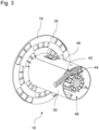
- a hose 32 in particular a garden hose, (at least partially in Fig. 2 or 3 pictured) can be rolled up.
- the housing 12 has a mounting section 20, via which the hose box 10 can be hung on a corresponding holder 22, here in the form of a wall bracket.
- the hose box 10 can also be hung in another way, for example on a hose trolley provided for this purpose.
- the hose box 10 has at least one holding and/or supporting element 24, 24' on the housing 12.
- the holding and/or carrying element 24, 24' is formed by a carrying handle.
- the housing of the hose box further includes a mounting section via which the hose box 10 can be hung on a corresponding holder.
- the hose box 10 includes a drive unit, not shown here, which is formed by an electric motor.
- the hose box 10 includes at least one battery pack interface (not shown), to which a battery pack (not shown) can be coupled to supply the drive unit with electrical energy.
- the battery pack interface and the drive unit are electrically connected to one another via lines not shown.
- the battery pack is designed as a removable battery pack, i.e. the battery pack can be exchangeable or exchangeable for another battery pack.
- the battery pack is designed as a removable battery pack or as a system battery pack; i.e. the battery pack can, in addition to the hose box 10 present here, be used universally to supply electrical energy for various electrical devices, for example a power tool, electric garden tool, household appliance, vehicles or the like.
- a protective housing 26 is provided to protect the battery pack interface and the battery pack coupled to it from moisture, dirt, dust or the like.
- the battery pack interface is arranged within this protective housing 26.
- the protective housing 26 is designed to be pivotable.
- the hose box 10 is also assigned an actuation unit 50, for example in the form of a switch, button or the like, by means of which the drive unit is controlled and a motorized winding of the hose 32 on the hose drum 16 is carried out.
- actuation unit 50 for example in the form of a switch, button or the like, by means of which the drive unit is controlled and a motorized winding of the hose 32 on the hose drum 16 is carried out.
- the housing 12 In order to gain access to the hose reel 16, the housing 12 includes an access opening with a removable housing section element 28.
- the housing section element 28 is attached to the housing 12 via releasable clamping and/or screw connections, not shown here.
- the hose drum 16 includes a drum jacket 30 with an at least largely cylindrical shape.
- Drum disks 18 are coupled and/or attached to the end faces of the drum shell 30.
- the drum disks 18 serve, among other things, to laterally limit the hose 32 that is wound or to be wound onto the drum jacket 30.
- the drum disks 18 have a plurality of drum disk openings 34, which have an angular cross section.
- the large number of drum disk openings 34 reduces the weight of the hose drum 16 and thus of the entire hose drum 16.
- the drum casing 30 comprises at least one cavity 36, within which a coupling connection 38 is provided.
- the coupling connection 38 is arranged on an inside of the drum disk 18 facing the cavity 36.
- the hose 32 can be coupled to this coupling connection 38 via a corresponding coupling piece, not shown here.
- the coupling connection 38 can be connected to a water connection via lines not shown here.
- At least two guide elements 40, 40 ' are provided within the at least one cavity 36.
- the at least two guide elements 40, 40' are designed to be bent or curved at least in sections.
- the bend or curvature of the at least two guide elements 40, 40' can be the same or different.
- the at least two guide elements 40, 40' can each be designed in such a way and in particular arranged at a distance from one another, so that the hose 32 is guided and/or laid at least in sections in a meandering shape around the at least two guide elements 40, 40'.
- the at least two guide elements 40, 40' also function as a strain relief element, since, for example, the forces that occur when unwinding the hose 32 no longer act directly on the coupling connection, but can be reduced.
- the at least one cavity 36 has a recess 42 which merges into the drum jacket 30, that is to say the drum jacket 30 is at least partially reduced in the area of the recess 42, whereby a guide for the hose 32 from the at least one cavity 36 to the hose drum 16 is provided.
- at least one further guide element 44 is provided in this area.
- the guide element 44 has a concave curvature on which the hose 32 can rest optimally.
- the at least one cavity 36 can be closed by means of a cover 46 in such a way that the cover is a component of the drum shell 30, i.e. the cover 46 has the same curvature as the drum shell 30.
- the cover 46 can be fastened to the drum casing 30 to cover the at least one cavity 36, for example via screwing and/or clamping means.
- the hose drum 16 has at least one further cavity 48, within which the drive unit is arranged.
Landscapes
- Storing, Repeated Paying-Out, And Re-Storing Of Elongated Articles (AREA)
Applications Claiming Priority (1)
| Application Number | Priority Date | Filing Date | Title |
|---|---|---|---|
| DE202022101881.2U DE202022101881U1 (de) | 2022-04-07 | 2022-04-07 | Schlauchbox |
Publications (1)
| Publication Number | Publication Date |
|---|---|
| EP4257529A1 true EP4257529A1 (fr) | 2023-10-11 |
Family
ID=81452718
Family Applications (1)
| Application Number | Title | Priority Date | Filing Date |
|---|---|---|---|
| EP23159672.7A Pending EP4257529A1 (fr) | 2022-04-07 | 2023-03-02 | Boîte à tubes |
Country Status (2)
| Country | Link |
|---|---|
| EP (1) | EP4257529A1 (fr) |
| DE (1) | DE202022101881U1 (fr) |
Families Citing this family (1)
| Publication number | Priority date | Publication date | Assignee | Title |
|---|---|---|---|---|
| FI4286311T3 (fi) | 2022-05-31 | 2024-07-23 | Husqvarna Ab | Letkukelakokoonpano |
Citations (2)
| Publication number | Priority date | Publication date | Assignee | Title |
|---|---|---|---|---|
| DE202021100427U1 (de) * | 2021-01-28 | 2021-02-08 | Einhell Germany Ag | Schlauchbox |
| EP3812329A1 (fr) * | 2019-10-24 | 2021-04-28 | Andreas Stihl AG & Co. KG | Unité de tambour à tuyau flexible et dispositif de tambour à tuyau flexible comprenant une unité de tambour à tuyau flexible |
-
2022
- 2022-04-07 DE DE202022101881.2U patent/DE202022101881U1/de active Active
-
2023
- 2023-03-02 EP EP23159672.7A patent/EP4257529A1/fr active Pending
Patent Citations (2)
| Publication number | Priority date | Publication date | Assignee | Title |
|---|---|---|---|---|
| EP3812329A1 (fr) * | 2019-10-24 | 2021-04-28 | Andreas Stihl AG & Co. KG | Unité de tambour à tuyau flexible et dispositif de tambour à tuyau flexible comprenant une unité de tambour à tuyau flexible |
| DE202021100427U1 (de) * | 2021-01-28 | 2021-02-08 | Einhell Germany Ag | Schlauchbox |
Also Published As
| Publication number | Publication date |
|---|---|
| DE202022101881U1 (de) | 2022-04-20 |
Similar Documents
| Publication | Publication Date | Title |
|---|---|---|
| DE112022001535B4 (de) | Zerlegungsmechanismus für Altbatteriemodul | |
| DE102008024007B4 (de) | Akkumulator-Einheit und damit ausgestattetes Elektrofahrzeug | |
| EP3678214B1 (fr) | Construction, bloc d'accumulateur et système de travaux de jardinage et / ou forestiers | |
| EP1921717B1 (fr) | Ensemble de montage pour une boîte électrique | |
| EP1516120A1 (fr) | Dispositif pour manipuler des pales de rotor | |
| EP4257529A1 (fr) | Boîte à tubes | |
| EP2819207A1 (fr) | Combinaison d'un système de support, d'une batterie et d'un appareil à entraîner | |
| DE102010040796B4 (de) | Ladeeinrichtung für ein Elektrofahrzeug | |
| DE102012205414B3 (de) | Elektrofahrzeug mit Wechselbatterie | |
| DE202021100429U1 (de) | Schlauchbox-Anordnung | |
| DE202024102881U1 (de) | Kabelabisolierzange | |
| DE7926920U1 (de) | Versorgungsgeraet zur elektrischen versorgung von mit einem elektromotor angetriebenen handwerkzeugen oder arbeitsgeraeten, insbesondere rasenkantenschneidern | |
| EP3678216B1 (fr) | Bloc d'accumulateur et système de travaux de jardinage et / ou de forestiers | |
| DE4118334A1 (de) | Batteriekabelverbinder | |
| DE202021100427U1 (de) | Schlauchbox | |
| EP2135333B1 (fr) | Câble de rallonge pour dispositifs d'usinage de tubes | |
| DE10013938C1 (de) | Netzanschaltkasten | |
| DE102019208809A1 (de) | Wischarmvorrichtung, Wischarm und Scheibenwischersystem | |
| AT521834B1 (de) | Aufwickelvorrichtung für Datenkabel | |
| CH628860A5 (en) | Power supply device for electrical garden appliances | |
| DE102010005425A1 (de) | Steckdose für eine Anhängerkupplungseinrichtung und Anhängerkupplungseinrichtung für einen Kraftwagen mit einer Steckdose | |
| CN208761832U (zh) | 一种输配电用电工程施工建设用放线装置 | |
| DE102006054374B4 (de) | Gerät zur Entfernung von Eis und Schnee von Hochspannungsleitungen | |
| DE102007054551B3 (de) | Baustromanschlussvorrichtung für Niederspannugsverteilung | |
| WO2001082434A1 (fr) | Enrouleur pour cable electrique a segments de cable extensibles |
Legal Events
| Date | Code | Title | Description |
|---|---|---|---|
| PUAI | Public reference made under article 153(3) epc to a published international application that has entered the european phase |
Free format text: ORIGINAL CODE: 0009012 |
|
| STAA | Information on the status of an ep patent application or granted ep patent |
Free format text: STATUS: THE APPLICATION HAS BEEN PUBLISHED |
|
| AK | Designated contracting states |
Kind code of ref document: A1 Designated state(s): AL AT BE BG CH CY CZ DE DK EE ES FI FR GB GR HR HU IE IS IT LI LT LU LV MC ME MK MT NL NO PL PT RO RS SE SI SK SM TR |
|
| STAA | Information on the status of an ep patent application or granted ep patent |
Free format text: STATUS: REQUEST FOR EXAMINATION WAS MADE |
|
| 17P | Request for examination filed |
Effective date: 20240404 |
|
| RBV | Designated contracting states (corrected) |
Designated state(s): AL AT BE BG CH CY CZ DE DK EE ES FI FR GB GR HR HU IE IS IT LI LT LU LV MC ME MK MT NL NO PL PT RO RS SE SI SK SM TR |
|
| GRAP | Despatch of communication of intention to grant a patent |
Free format text: ORIGINAL CODE: EPIDOSNIGR1 |
|
| STAA | Information on the status of an ep patent application or granted ep patent |
Free format text: STATUS: GRANT OF PATENT IS INTENDED |
|
| GRAJ | Information related to disapproval of communication of intention to grant by the applicant or resumption of examination proceedings by the epo deleted |
Free format text: ORIGINAL CODE: EPIDOSDIGR1 |
|
| STAA | Information on the status of an ep patent application or granted ep patent |
Free format text: STATUS: REQUEST FOR EXAMINATION WAS MADE |
|
| RIC1 | Information provided on ipc code assigned before grant |
Ipc: B65H 75/44 20060101AFI20251022BHEP |
|
| INTG | Intention to grant announced |
Effective date: 20251030 |
|
| INTC | Intention to grant announced (deleted) | ||
| GRAP | Despatch of communication of intention to grant a patent |
Free format text: ORIGINAL CODE: EPIDOSNIGR1 |
|
| STAA | Information on the status of an ep patent application or granted ep patent |
Free format text: STATUS: GRANT OF PATENT IS INTENDED |
|
| INTG | Intention to grant announced |
Effective date: 20260114 |
|
| GRAS | Grant fee paid |
Free format text: ORIGINAL CODE: EPIDOSNIGR3 |