EP3678833B1 - Procédé et dispositif pour nettoyer une masse fondue de polymère - Google Patents
Procédé et dispositif pour nettoyer une masse fondue de polymère Download PDFInfo
- Publication number
- EP3678833B1 EP3678833B1 EP18769606.7A EP18769606A EP3678833B1 EP 3678833 B1 EP3678833 B1 EP 3678833B1 EP 18769606 A EP18769606 A EP 18769606A EP 3678833 B1 EP3678833 B1 EP 3678833B1
- Authority
- EP
- European Patent Office
- Prior art keywords
- polymer melt
- melt
- vacuum chamber
- filter element
- vacuum
- Prior art date
- Legal status (The legal status is an assumption and is not a legal conclusion. Google has not performed a legal analysis and makes no representation as to the accuracy of the status listed.)
- Active
Links
Images

Classifications
-
- B—PERFORMING OPERATIONS; TRANSPORTING
- B29—WORKING OF PLASTICS; WORKING OF SUBSTANCES IN A PLASTIC STATE IN GENERAL
- B29C—SHAPING OR JOINING OF PLASTICS; SHAPING OF MATERIAL IN A PLASTIC STATE, NOT OTHERWISE PROVIDED FOR; AFTER-TREATMENT OF THE SHAPED PRODUCTS, e.g. REPAIRING
- B29C48/00—Extrusion moulding, i.e. expressing the moulding material through a die or nozzle which imparts the desired form; Apparatus therefor
- B29C48/25—Component parts, details or accessories; Auxiliary operations
- B29C48/36—Means for plasticising or homogenising the moulding material or forcing it through the nozzle or die
- B29C48/50—Details of extruders
- B29C48/76—Venting, drying means; Degassing means
- B29C48/768—Venting, drying means; Degassing means outside the apparatus, e.g. after the die
-
- B—PERFORMING OPERATIONS; TRANSPORTING
- B01—PHYSICAL OR CHEMICAL PROCESSES OR APPARATUS IN GENERAL
- B01D—SEPARATION
- B01D19/00—Degasification of liquids
- B01D19/0042—Degasification of liquids modifying the liquid flow
-
- B—PERFORMING OPERATIONS; TRANSPORTING
- B29—WORKING OF PLASTICS; WORKING OF SUBSTANCES IN A PLASTIC STATE IN GENERAL
- B29C—SHAPING OR JOINING OF PLASTICS; SHAPING OF MATERIAL IN A PLASTIC STATE, NOT OTHERWISE PROVIDED FOR; AFTER-TREATMENT OF THE SHAPED PRODUCTS, e.g. REPAIRING
- B29C48/00—Extrusion moulding, i.e. expressing the moulding material through a die or nozzle which imparts the desired form; Apparatus therefor
- B29C48/25—Component parts, details or accessories; Auxiliary operations
- B29C48/36—Means for plasticising or homogenising the moulding material or forcing it through the nozzle or die
- B29C48/50—Details of extruders
- B29C48/69—Filters or screens for the moulding material
- B29C48/694—Cylindrical or conical filters
-
- D—TEXTILES; PAPER
- D01—NATURAL OR MAN-MADE THREADS OR FIBRES; SPINNING
- D01D—MECHANICAL METHODS OR APPARATUS IN THE MANUFACTURE OF ARTIFICIAL FILAMENTS, THREADS, FIBRES, BRISTLES OR RIBBONS
- D01D1/00—Treatment of filament-forming or like material
- D01D1/10—Filtering or de-aerating the spinning solution or melt
- D01D1/106—Filtering
-
- B—PERFORMING OPERATIONS; TRANSPORTING
- B01—PHYSICAL OR CHEMICAL PROCESSES OR APPARATUS IN GENERAL
- B01D—SEPARATION
- B01D29/00—Filters with filtering elements stationary during filtration, e.g. pressure or suction filters, not covered by groups B01D24/00 - B01D27/00; Filtering elements therefor
- B01D29/50—Filters with filtering elements stationary during filtration, e.g. pressure or suction filters, not covered by groups B01D24/00 - B01D27/00; Filtering elements therefor with multiple filtering elements, characterised by their mutual disposition
- B01D29/52—Filters with filtering elements stationary during filtration, e.g. pressure or suction filters, not covered by groups B01D24/00 - B01D27/00; Filtering elements therefor with multiple filtering elements, characterised by their mutual disposition in parallel connection
-
- B—PERFORMING OPERATIONS; TRANSPORTING
- B29—WORKING OF PLASTICS; WORKING OF SUBSTANCES IN A PLASTIC STATE IN GENERAL
- B29B—PREPARATION OR PRETREATMENT OF THE MATERIAL TO BE SHAPED; MAKING GRANULES OR PREFORMS; RECOVERY OF PLASTICS OR OTHER CONSTITUENTS OF WASTE MATERIAL CONTAINING PLASTICS
- B29B13/00—Conditioning or physical treatment of the material to be shaped
- B29B13/10—Conditioning or physical treatment of the material to be shaped by grinding, e.g. by triturating; by sieving; by filtering
-
- B—PERFORMING OPERATIONS; TRANSPORTING
- B29—WORKING OF PLASTICS; WORKING OF SUBSTANCES IN A PLASTIC STATE IN GENERAL
- B29C—SHAPING OR JOINING OF PLASTICS; SHAPING OF MATERIAL IN A PLASTIC STATE, NOT OTHERWISE PROVIDED FOR; AFTER-TREATMENT OF THE SHAPED PRODUCTS, e.g. REPAIRING
- B29C48/00—Extrusion moulding, i.e. expressing the moulding material through a die or nozzle which imparts the desired form; Apparatus therefor
- B29C48/25—Component parts, details or accessories; Auxiliary operations
- B29C48/255—Flow control means, e.g. valves
- B29C48/2554—Flow control means, e.g. valves provided in or in the proximity of filter devices
-
- B—PERFORMING OPERATIONS; TRANSPORTING
- B29—WORKING OF PLASTICS; WORKING OF SUBSTANCES IN A PLASTIC STATE IN GENERAL
- B29C—SHAPING OR JOINING OF PLASTICS; SHAPING OF MATERIAL IN A PLASTIC STATE, NOT OTHERWISE PROVIDED FOR; AFTER-TREATMENT OF THE SHAPED PRODUCTS, e.g. REPAIRING
- B29C48/00—Extrusion moulding, i.e. expressing the moulding material through a die or nozzle which imparts the desired form; Apparatus therefor
- B29C48/25—Component parts, details or accessories; Auxiliary operations
- B29C48/36—Means for plasticising or homogenising the moulding material or forcing it through the nozzle or die
- B29C48/50—Details of extruders
- B29C48/69—Filters or screens for the moulding material
- B29C48/693—Substantially flat filters mounted at the end of an extruder screw perpendicular to the feed axis
-
- B—PERFORMING OPERATIONS; TRANSPORTING
- B29—WORKING OF PLASTICS; WORKING OF SUBSTANCES IN A PLASTIC STATE IN GENERAL
- B29C—SHAPING OR JOINING OF PLASTICS; SHAPING OF MATERIAL IN A PLASTIC STATE, NOT OTHERWISE PROVIDED FOR; AFTER-TREATMENT OF THE SHAPED PRODUCTS, e.g. REPAIRING
- B29C48/00—Extrusion moulding, i.e. expressing the moulding material through a die or nozzle which imparts the desired form; Apparatus therefor
- B29C48/25—Component parts, details or accessories; Auxiliary operations
- B29C48/36—Means for plasticising or homogenising the moulding material or forcing it through the nozzle or die
- B29C48/50—Details of extruders
- B29C48/76—Venting, drying means; Degassing means
Definitions
- the invention relates to a method for cleaning a polymer melt according to the preamble of claim 1 and a device for cleaning a polymer melt according to the preamble of claim 10.
- thermoplastics When processing thermoplastics, it is generally known that in an extrusion process, for example to produce strand-shaped products, the polymer melt must be largely cleaned of foreign substances.
- Some thermoplastics contain certain amounts of monomers, oligomers, solvents and other volatile components as residues from the manufacturing process.
- Other polymers such as polyamide are very hygroscopic, so they have a strong tendency to absorb moisture. The absorbed moisture can be trapped or absorbed inside the polymer.
- volatile foreign substances when granular polymers are melted, large amounts of air are incorporated into the melt.
- solid foreign substances contaminations in the polymer melt, which are referred to here as solid foreign substances.
- Such solid foreign substances are impurities that are contained in the granulate, for example, or come from abrasion of machine parts.
- decomposition products also occur within the melt, which can lead to unwanted thread breaks, for example during fiber production.
- the polymer melt is filtered using filter elements. This process step is usually carried out using filter devices, such as those from the DE 199 12 433 A1
- the polymer melt is passed through a filter element which, depending on the filter fineness, filters out the solid foreign matter from the melt stream of the polymer melt.
- DD 231 029 A1 a procedure and a Device for compounding thermoplastics with filter and degassing.
- Other examples are the EP 0 705 677 A1 , the WO 2005/087477 A1 , the CN 107 053 635 A , the EP 2 439 044 A1 , the EP 2 008 784 A1 and the AT 511 574 A1 .
- a further aim of the invention is to be able to carry out the cleaning of the polymer melt with little equipment expenditure.
- the object is achieved according to the invention by a method having the features of claim 1 and by a device having the features of claim 9.
- the invention departs from the classic division and sequence of degassing and filtration for cleaning the polymer melt. It was found that the success of degassing does not depend on whether foreign particles are contained in the polymer melt. On the contrary, the homogeneity of the polymer melt promotes the escape of the volatile foreign substances.
- the polymer melt is pressed through a filter element into a vacuum in a vacuum chamber. The solid foreign substances are absorbed by the filter element and the volatile Foreign substances are collected in the vacuum chamber. This allows both process steps for cleaning the polymer melt to be combined into one process step.
- the device according to the invention has only one filter element and a vacuum of a vacuum chamber. This allows the cleaning of a polymer melt to be carried out in one process step with little equipment outlay.
- the polymer melt is pressed through the filter element into the vacuum chamber of the vacuum chamber.
- the process variant in which the polymer melt is guided within the vacuum chamber to an exit surface of the filter element is particularly advantageous.
- this allows relatively large melt surfaces to be created within the vacuum chamber, which promote the escape of volatile foreign substances.
- the melt surface at the exit surface of the filter element is constantly renewed via the flow through the filter element.
- the volatile foreign substances emerging from the polymer melt are continuously removed from the vacuum chamber through a degassing opening. This ensures material separation and the volatile foreign substances can be processed separately and used if necessary.
- the vacuum is set to a negative pressure in the range of 0.5 mbar to 50 mbar.
- the negative pressure The vacuum within the vacuum chamber is selected depending on the thickness of the polymer melt at the outlet surface of the filter element. This creates a relatively high vacuum in order to achieve intensive degassing with relatively thick melt layers.
- the cleaned polymer melt is collected in a sump of the vacuum chamber formed below the filter element and discharged through a melt outlet.
- a continuous melt flow can be achieved, so that the cleaning of the polymer melt can be integrated into an extrusion process without any problems.
- the polymer melt is fed via a melt inlet into a pressure chamber limited by the filter element at an overpressure. This allows the melt throughput at the filter element to be adjusted depending on the overpressure.
- the polymer melt is filtered with a filter element fineness in the range of 40 ⁇ m to 1,000 ⁇ m.
- a filter element fineness in the range of 40 ⁇ m to 1,000 ⁇ m.
- the polymer melt is introduced into the pressure chamber with an overpressure in the range of 10 bar to 100 bar.
- the polymer melt is heated to a temperature.
- the polymer melt is heated to a temperature above 200°C.
- the device according to the invention provides that the filter element is formed from at least one hollow cylindrical filter candle that protrudes into the vacuum chamber.
- the outer sides of the filter candle are used to obtain the largest possible outer surface for guiding the melt after filtration.
- the filter elements are designed with a filter surface on the inlet side that is smaller than an outlet surface, along which the melt is guided for the purpose of degassing.
- the development of the device according to the invention is provided in which the vacuum chamber is connected to a collecting container and a vacuum pump via a degassing opening.
- the vacuum pump is designed in such a way that the vacuum in the vacuum chamber can be generated to a negative pressure in the range of 0.5 mbar to 50 mbar.
- the cleaned melt is preferably collected in a bottom area of the vacuum chamber.
- a sump is formed which extends below the filter element and which is connected to a melt outlet in a chamber housing.
- the chamber housing also has a melt inlet that opens into a pressure chamber delimited by the filter element. This allows a melt stream of the polymer melt to be introduced directly into the pressure chamber and guided to the filter element.
- the filter element has a filter fineness in the range of 40 ⁇ m to 1,000 ⁇ m.
- the filter fineness depends on the manufacturing process or the product to be manufactured.
- the melt inlet can be advantageously connected directly to a pressure source through which the polymer melt can be introduced into the pressure chamber at an overpressure in the range of 10 bar to 100 bar.
- a pressure source through which the polymer melt can be introduced into the pressure chamber at an overpressure in the range of 10 bar to 100 bar.
- An extruder or a pump can be used as a pressure source.
- a heating device is assigned to the chamber housing to control the temperature of the polymer melt.
- the polymer melt can thus be kept at a predetermined temperature before and after cleaning.
- the method and the device according to the invention are suitable for all extrusion processes in which a polymer melt is processed.
- polymer melts from a recycling process can also be cleaned.
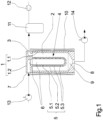
- a first embodiment of the device according to the invention for cleaning a polymer melt is shown schematically in a cross-sectional view.
- the embodiment has a chamber housing 1, which in this example is formed by a cylindrical pot 1.1 and a lid 1.2.
- the pot 1.1 contains a vacuum chamber 2.
- a filter element 4 is held centrally on the pot 1.1.
- the filter element 4 is designed as a filter candle 5 and protrudes into the vacuum chamber 2.
- the filter candle 5 is designed as a hollow cylinder and has a pressure chamber 6 inside, which is connected to a melt inlet 7 in the chamber housing 1.
- the melt inlet 7 is formed here on the lid 1.2.
- the filter candle 5 is closed at a free end and has a filter material 5.1 on the inside and a support wall 5.2 on the outer circumference.
- the support wall 5.2 has a plurality of outlet openings 5.3 and forms an outer outlet surface for guiding the filtered polymer melt within the vacuum chamber 2.
- a sump 9 is formed in the bottom of the pot 1.1 in the vacuum chamber 2.
- the sump 9 is connected to a melt outlet 8 in the chamber housing 1.
- the melt outlet 8 is arranged centrally in the bottom of the pot 1.1, with the sump 9 extending in a funnel shape above the melt outlet 8.
- the vacuum chamber 2 is connected to a collecting container 11 and a vacuum pump 12 via a degassing opening 3 in the chamber housing 1.
- the degassing opening 3 is formed in the pot 1.1 of the chamber housing 1.
- a heating device 10 is arranged on the circumference of the chamber housing 1.
- the heating device 10 preferably has electrical heating means, which are not shown here.
- the melt inlet 7 on the chamber housing 1 is connected to a pressure source 13.
- the pressure source 13 is formed by a pump. The pump 13 allows the polymer melt to be continuously fed to the melt inlet 7 as a melt stream.
- a discharge pump 14 is connected to the melt outlet 8.
- the discharge pump 14 discharges the cleaned polymer melt with a continuous discharge stream.
- a vacuum with a negative pressure in the range of 0.5 mbar to 50 mbar is first set in the vacuum chamber 2 via the vacuum pump 12.
- the level of the vacuum in the vacuum chamber 2 depends on the process and on the filter elements 4 used.
- a polymer melt is fed to the filter element 4 via the melt inlet 7 via the pressure source 13.
- the polymer melt is fed with an overpressure in the range of 10 bar to 100 bar.
- the pressure chamber 6 inside the filter candle 5 fills up so that the polymer melt is pressed through the filter material 5.1 for filtration.
- the solid foreign substances are absorbed by the filter material 5.1 depending on the filter fineness.
- the polymer melt then penetrates the outlet openings 5.3 in the support wall 5.2.
- the polymer melt adheres to the outlet surface of the support wall 5.2 of the filter candle 5 and slides due to gravity within the vacuum chamber in the direction of the sump 9.
- the polymer melt guided along the outlet surface of the support wall 5.2 forms a jacket-shaped melt surface within the vacuum chamber 2, which is directly exposed to the vacuum.
- the volatile foreign substances are removed from the polymer melt and collected within the vacuum chamber 2.
- the volatile foreign substances are removed via the degassing opening 3 and collected in the collection container 11.
- the volatile foreign substances can be processed within the collection container 11 and separated, for example, into gaseous and liquid media.
- the cleaned polymer melt accumulating in the sump 9 is discharged via the melt outlet 8.
- the discharge pump 14 is connected to the melt outlet 8, so that a continuous melt flow can be generated.
- a level sensor it is possible for a level sensor to be arranged within the vacuum chamber 2, which interacts with a pump control in such a way that an essentially constant melt flow is ensured.
- the pump control can act on the pressure source or the discharge pump or on both.
- the heating device 10 is provided on the circumference of the chamber housing 1.
- the heating device 10, which preferably has electrical heating means, ensures a melt temperature of above 200°C. Temperatures of up to 330°C may be required to keep the polymer melt at the right temperature. These essentially depend on the polymer type of the polymer melt to be cleaned.
- the method and the device according to the invention are basically suitable for all thermoplastic melts.
- the combined filtration and degassing enables the polymer melt to be cleaned with relatively short residence times.
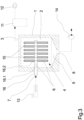
- FIG. 2 another embodiment of the device according to the invention is shown schematically in a cross-sectional view.
- the embodiment is essentially identical to the aforementioned embodiment according to Fig. 1 , so that at this point only the differences are explained and otherwise reference is made to the above description.
- filter elements 4 are provided, which protrude into a vacuum chamber 2.
- three filter candles 5 are arranged parallel to one another and connected to the melt inlet 7 and the pressure chamber 6.
- the number of filter elements 4 is exemplary. In principle, a large number of filter elements in the range of 100 to 150 can be used to carry out combined filtration and degassing to clean the polymer melt.
- the degassing opening 3 is formed in the upper region of the vacuum chamber 2 in the pot 1.1 of the chamber housing 1.
- a collecting container 11 and a vacuum pump 12 are connected to the degassing opening 2.
- a sump 9 is formed in the vacuum chamber 2.
- the sump 9 is connected to a melt outlet 8.
- a pressure source 13 in the form of an extruder is provided.
- an outlet side of the extruder is connected directly to the melt inlet 7 of the cleaning device.
- the outlet surfaces provided by the filter elements are always larger than a filter surface for filtering the polymer melt.
- the polymer melt is pressed from the inside to the outside at the filter candles 5, whereby the outlet surface on the circumference of the filter candles 5 creates the melt surfaces for degassing.
- filter elements other than filter candles are also suitable for carrying out combined filtration and degassing.
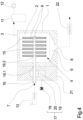
- Fig. 3 For this purpose, a further embodiment not belonging to the claimed invention is shown in which the filter elements are formed by filter disks.
- FIG. 3 An embodiment of a device not according to the invention is shown schematically in a cross-sectional view.
- the Fig. 3 The embodiment shown has a chamber housing 1 in which a vacuum chamber 2 is formed.
- the vacuum chamber 2 is connected to a collecting container 11 and a vacuum pump 12 via a degassing opening 3.
- a plurality of filter elements 4 are arranged within the vacuum chamber 2.
- the filter elements 4 are formed by filter disks 15 which are held on the circumference of a mandrel 16.
- the mandrel 16 forms a melt channel 16.1 inside, which has several distribution openings 16.2, each with a pressure chamber 6 of the filter disks 15.
- the mandrel 16 penetrates the chamber housing 1 to the outside and forms a melt inlet 7 at an open end.
- a sump 9 is formed within the vacuum chamber 2 below the vertically aligned filter disks.
- the sump 9 is funnel-shaped and connected to a lower melt outlet 8 in the chamber housing 1.
- the melt outlet 8 and the degassing opening 3 are located opposite each other in the vacuum chamber 2.
- the melt inlet 7 can be connected directly to an extruder as a pressure source 13.
- the polymer melt is guided via the melt channel 16.1 and the distribution opening 16.2 into the pressure chambers 6 of the filter disks 15.
- the filter disks 15 have a filter material in order to filter the solid foreign substances from the polymer melt.
- the filter material can have a filter fineness in the range of 40 ⁇ m to 1,000 ⁇ m.
- the degassing of the polymer melt takes place.
- the volatile foreign substances that are released are fed to the collecting container 11 via the degassing opening 3.
- the vacuum set by the vacuum pump 12 is in a range from 0.5 mbar to 50 mbar.
- the cleaned polymer melt is discharged from the vacuum chamber via the melt outlet by the discharge pump 14 in a continuous melt stream. 2. At higher flow rates, the polymer melt could alternatively be conveyed through a discharge extruder.
- the heating device 10 for controlling the temperature of the chamber housing 1 was not shown in detail.
- the number of filter disks shown is also an example. In principle, a higher number of filter disks can also be used for the combined filtration and degassing of the polymer melt.
- FIG. 4 an alternative embodiment of the device according to the invention is shown.
- the embodiment according to Fig. 4 is essentially identical to the embodiment according to Fig. 3 , so that only the differences are explained below and otherwise reference is made to the above description of the Fig. 3 is taken.
- a drive housing 21 is arranged next to the chamber housing 1.
- the drive housing 21 is penetrated by the mandrel 16, the mandrel 16 holding several filter disks 15 at a closed end within a vacuum chamber 2 and a free end of the mandrel 16 forming a melt inlet 7 outside the drive housing 21.
- the mandrel 16 is rotatably mounted within the drive housing 21 and coupled to a drive shaft 20 via a gear pair 18.
- the drive shaft 20 is connected to a motor 19.
- the mandrel 16 can thus be set in a rotary movement via the motor 19, so that the filter disks 15 held within the vacuum chamber 2 rotate at a predetermined peripheral speed. This creates a pressure on the exit surfaces of the filter disks. 15 forming melt layer moves, which promotes a renewal of the melt surface.
- a discharge extruder 22 is connected to the melt outlet 8 of the chamber housing 1.
- the discharge extruder 22 is shown in a horizontal arrangement in order to continuously convey the purified polymer melt.
- the discharge extruder 22 could also be kept in a vertical arrangement in order to generate a continuous melt flow of the purified polymer melt.
- Fig. 1 to 4 The arrangement and choice of filter elements in the embodiments of the device according to the invention for cleaning the polymer melt are exemplary.
- the filter candles shown can be Fig. 1 and 2 can also be held in a different installation position in the vacuum chamber. Vertical, horizontal or angled installation positions are possible.
- the filter elements are preferably designed to be replaceable in order to remove solid foreign matter from the filter elements.
- extruders or pumps as well as discharge pumps and discharge extruders on the outlet side can be used as pressure media in the embodiments shown according to Fig. 1 to Fig. 4 can be combined as desired.
Landscapes
- Engineering & Computer Science (AREA)
- Mechanical Engineering (AREA)
- Textile Engineering (AREA)
- Chemical & Material Sciences (AREA)
- Chemical Kinetics & Catalysis (AREA)
- Extrusion Moulding Of Plastics Or The Like (AREA)
- Addition Polymer Or Copolymer, Post-Treatments, Or Chemical Modifications (AREA)
Claims (16)
- Procédé de purification d'une masse fondue de polymère, dans lequel on élimine de la masse fondue de polymère des impuretés volatiles et des impuretés solides, dans lequel la masse fondue de polymère est comprimée par un élément filtrant dans un vide d'une chambre à vide, dans lequel les impuretés solides sont reprises par l'élément filtrant, et dans lequel les impuretés volatiles sont collectées dans la chambre à vide, et dans lequel la masse fondue de polymère est, à l'intérieur de la chambre à vide, envoyée à une surface de sortie de l'élément filtrant, caractérisé en ce que l'élément filtrant est formé d'au moins une bougie filtrante cylindrique creuse, qui pénètre dans la chambre à vide.
- Procédé selon la revendication 1, caractérisé en ce que les impuretés volatiles sont évacuées de la chambre à vide par un orifice de dégazage.
- Procédé selon l'une des revendications 1 ou 2, caractérisé en ce que le vide dans la chambre à vide est ajusté à une dépression dans la plage de 0,5 mbar à 50 mbar.
- Procédé selon l'une des revendications 1 à 3, caractérisé en ce que la masse fondue de polymère est collectée dans une fosse de la chambre à vide, réalisée en dessous de l'élément filtrant, et est évacuée par une sortie de masse fondue.
- Procédé selon l'une des revendications 1 à 4, caractérisé en ce que la masse fondue de polymère est introduite en surpression, par une entrée de masse fondue, dans un compartiment sous pression délimité par l'élément filtrant.
- Procédé selon la revendication 5, caractérisé en ce que la masse fondue de polymère est filtrée jusqu'à une finesse de filtration de l'élément filtrant dans la plage de 40 µm à 1 000 µm.
- Procédé selon la revendication 6, caractérisé en ce que la masse fondue de polymère est introduite dans le compartiment sous pression avec une surpression dans la plage de 10 bar à 100 bar.
- Procédé selon l'une des revendications 1 à 7, caractérisé en ce que la masse fondue de polymère est, avant la purification, chauffée à une température supérieure à 200 °C.
- Dispositif de purification d'une masse fondue de polymère, par lequel des impuretés volatiles et des impuretés solides peuvent être éliminées de la masse fondue de polymère, comprenant un élément filtrant (4) et un vide d'une chambre à vide (2), dans lequel la masse fondue de polymère peut être guidée dans le vide de la chambre à vide (2) en passant dans l'élément filtrant, dans lequel l'élément filtrant (4) lie les impuretés solides, et dans lequel la chambre à vide (2) reprend les impuretés volatiles, caractérisé en ce que l'élément filtrant (4) est formé au moins d'une bougie filtrante cylindrique creuse (5), qui pénètre dans la chambre à vide (2).
- Dispositif selon la revendication 9, caractérisé en ce que la chambre à vide (2) est, par un orifice de dégazage (3), reliée à un réservoir (11) et à une pompe à vide (12).
- Dispositif selon la revendication 10, caractérisé en ce que le vide dans la chambre à vide (2) peut être produit par une pompe à vide (12) jusqu'à une dépression dans la plage de 0,5 mbar à 50 mbar.
- Dispositif selon l'une des revendications 8 à 11, caractérisé en ce que, dans une zone de fond de la chambre à vide (2), une fosse (9) est réalisée en dessous de l'élément filtrant (4), qui est reliée à une sortie de masse fondue (8) dans un carter de chambre (1).
- Dispositif selon la revendication 12, caractérisé en ce que le carter de chambre (1) présente une entrée de masse fondue (7), qui débouche dans un compartiment sous pression (6) délimité par l'élément filtrant (4).
- Dispositif selon l'une des revendications 9 à 13, caractérisé en ce que l'élément filtrant (4) présente une finesse de filtration dans la plage de 40 µm à 1 000 µηι.
- Dispositif selon la revendication 13 ou 14, caractérisé en ce que l'entrée de masse fondue (7) peut être reliée à une source de pression (13), par laquelle la masse fondue de polymère peut être introduite dans le compartiment sous pression (6) sous une surpression dans la plage de 10 bar à 100 bar.
- Dispositif selon l'une des revendications 9 à 15, caractérisé en ce qu'un dispositif de chauffage (10) est prévu pour équilibrer la température du carter de chambre (1).
Applications Claiming Priority (2)
| Application Number | Priority Date | Filing Date | Title |
|---|---|---|---|
| DE102017008320.7A DE102017008320A1 (de) | 2017-09-05 | 2017-09-05 | Verfahren und Vorrichtung zum Reinigen einer Polymerschmelze |
| PCT/EP2018/073561 WO2019048364A1 (fr) | 2017-09-05 | 2018-09-03 | Procédé et dispositif pour nettoyer une masse fondue de polymère |
Publications (3)
| Publication Number | Publication Date |
|---|---|
| EP3678833A1 EP3678833A1 (fr) | 2020-07-15 |
| EP3678833C0 EP3678833C0 (fr) | 2025-01-22 |
| EP3678833B1 true EP3678833B1 (fr) | 2025-01-22 |
Family
ID=63586660
Family Applications (1)
| Application Number | Title | Priority Date | Filing Date |
|---|---|---|---|
| EP18769606.7A Active EP3678833B1 (fr) | 2017-09-05 | 2018-09-03 | Procédé et dispositif pour nettoyer une masse fondue de polymère |
Country Status (5)
| Country | Link |
|---|---|
| US (1) | US11639018B2 (fr) |
| EP (1) | EP3678833B1 (fr) |
| CN (1) | CN111051037B (fr) |
| DE (1) | DE102017008320A1 (fr) |
| WO (1) | WO2019048364A1 (fr) |
Families Citing this family (1)
| Publication number | Priority date | Publication date | Assignee | Title |
|---|---|---|---|---|
| CN116377602A (zh) * | 2023-04-20 | 2023-07-04 | 无锡金通高纤股份有限公司 | 纺丝设备 |
Citations (1)
| Publication number | Priority date | Publication date | Assignee | Title |
|---|---|---|---|---|
| AT511574A1 (de) * | 2011-03-10 | 2012-12-15 | Next Generation Recyclingmaschinen Gmbh | Verfahren und vorrichtung zum entfernen von verunreinigungen aus einer kunststoffschmelze |
Family Cites Families (11)
| Publication number | Priority date | Publication date | Assignee | Title |
|---|---|---|---|---|
| DE231029C (de) | 1909-11-05 | 1911-02-11 | Rudolf Oheim | Tiefporen-Erzeuger mit auf einer Achse angeordneten Messerscheiben |
| DD231029A1 (de) * | 1984-05-10 | 1985-12-18 | Endler Fritz Dr Dr Ing | Verfahren und einrichtung zum compoundieren von thermoplasten, insbesondere thermoplastabfaellen |
| JPH08104899A (ja) | 1994-10-04 | 1996-04-23 | Sato Tekkosho:Kk | 多段式真空練り出し成形装置 |
| DE19912433A1 (de) | 1998-03-20 | 1999-09-23 | Barmag Barmer Maschf | Filtervorrichtung zur Filtration von Kunststoffschmelze |
| DE50210766D1 (de) | 2002-09-20 | 2007-10-04 | Basf Ag | Vorrichtung und Verfahren zum Extrudieren von Thermoplasten und Verwendung davon. |
| UA74926C2 (en) * | 2004-03-16 | 2006-02-15 | Yevhenii Petrovych Barmashyn | Extruder for processing of thermoplastic polymeric materials with area of filtration and degassing |
| AT503014B1 (de) * | 2006-04-27 | 2007-07-15 | Schulz Helmuth | Vorrichtung zum extrudieren von thermoplastischem kunststoffgut |
| EP2008784B1 (fr) | 2007-06-25 | 2013-02-27 | Gala Industries, Inc. | Procédé et appareil pour produire des granules de polymère contenant des volatils et/ou un matériau générant un volatil |
| DE102010047482A1 (de) | 2010-10-06 | 2012-04-12 | Diamat Maschinenbau Gmbh | Extrudieranlage |
| AT513443B1 (de) * | 2012-09-12 | 2016-08-15 | Next Generation Recyclingmaschinen Gmbh | Verfahren und Vorrichtung zum Erhöhen der Grenzviskosität einer Polykondensatschmelze |
| CN107053635A (zh) | 2016-12-14 | 2017-08-18 | 泗县鸿盛塑业有限公司 | 挤塑机 |
-
2017
- 2017-09-05 DE DE102017008320.7A patent/DE102017008320A1/de active Pending
-
2018
- 2018-09-03 EP EP18769606.7A patent/EP3678833B1/fr active Active
- 2018-09-03 WO PCT/EP2018/073561 patent/WO2019048364A1/fr not_active Ceased
- 2018-09-03 US US16/641,902 patent/US11639018B2/en active Active
- 2018-09-03 CN CN201880057482.0A patent/CN111051037B/zh active Active
Patent Citations (1)
| Publication number | Priority date | Publication date | Assignee | Title |
|---|---|---|---|---|
| AT511574A1 (de) * | 2011-03-10 | 2012-12-15 | Next Generation Recyclingmaschinen Gmbh | Verfahren und vorrichtung zum entfernen von verunreinigungen aus einer kunststoffschmelze |
Also Published As
| Publication number | Publication date |
|---|---|
| EP3678833C0 (fr) | 2025-01-22 |
| CN111051037A (zh) | 2020-04-21 |
| EP3678833A1 (fr) | 2020-07-15 |
| WO2019048364A1 (fr) | 2019-03-14 |
| DE102017008320A1 (de) | 2019-03-07 |
| US20200198210A1 (en) | 2020-06-25 |
| CN111051037B (zh) | 2023-03-14 |
| US11639018B2 (en) | 2023-05-02 |
Similar Documents
| Publication | Publication Date | Title |
|---|---|---|
| DE112013004438B4 (de) | Verfahren zum Erhöhen der Grenzviskosität einer Polykondensatschmelze | |
| DE2135793C2 (de) | Vorrichtung zum Abscheiden von Verunreinigungen aus einem Strom geschmolzenen polymeren Materials | |
| EP2419255B1 (fr) | Procede et dispositif de recyclage de matieres plastiques | |
| EP3259109B1 (fr) | Dispositif et procede de filtration | |
| DE2406649C2 (de) | Durchfluß-Kontrolleinheit | |
| DE202016101935U1 (de) | Extrusionsanlage zur Herstellung von Formstücken aus Kunststoffen | |
| WO1993004841A1 (fr) | Dispositif pour l'extrusion de produits thermoplastiques | |
| EP3883741A1 (fr) | Procédé et dispositif pour le recyclage de matières plastiques | |
| EP2994289B1 (fr) | Procédé d'exploitation d'un filtre à tamis rotatif | |
| EP1556203A1 (fr) | Dispositif pour extruder des thermoplastes | |
| EP3363609B1 (fr) | Dispositif et procédé de traitement d'une matière plastique fondue | |
| EP3678833B1 (fr) | Procédé et dispositif pour nettoyer une masse fondue de polymère | |
| EP4452598B1 (fr) | Ligne d'extrusion de film soufflé et procédé de production d'une bande de film | |
| DE102007056610B4 (de) | Verfahren zum Extrudieren von Kunststoffteilen | |
| WO2020104434A1 (fr) | Procédé et dispositif pour le filage à l'état fondu de filaments | |
| DE4406549A1 (de) | Verfahren zum Reinigen von polymeren Kunststoffen und Vorrichtung zur Ausübung des Verfahrens | |
| DE4010692C2 (de) | Verfahren zur Entgasung von Kunststoffschmelze in einem Schneckenextruder | |
| DE19912433A1 (de) | Filtervorrichtung zur Filtration von Kunststoffschmelze | |
| EP3927519A1 (fr) | Procédé et dispositif servant à filtrer une matière fondue polymère | |
| AT516967B1 (de) | Anlage sowie Verfahren zur Behandlung einer Kunststoffschmelze | |
| DE19732458C1 (de) | Vorrichtung und Verfahren zur Filtration von hochviskosen Polymerschmelzen | |
| EP2447028B1 (fr) | Procédé de purification de polymères thermoplastiques | |
| AT516968B1 (de) | Anlage sowie Verfahren zur Behandlung einer Kunststoffschmelze | |
| DE102022003870A1 (de) | Vorrichtung zur Herstellung von synthetischen Fäden aus wiederaufbereiteten Kunststoffabfällen | |
| DE102019004051A1 (de) | Verfahren und Vorrichtung zum Schmelzspinnen von Filamenten |
Legal Events
| Date | Code | Title | Description |
|---|---|---|---|
| STAA | Information on the status of an ep patent application or granted ep patent |
Free format text: STATUS: UNKNOWN |
|
| STAA | Information on the status of an ep patent application or granted ep patent |
Free format text: STATUS: THE INTERNATIONAL PUBLICATION HAS BEEN MADE |
|
| PUAI | Public reference made under article 153(3) epc to a published international application that has entered the european phase |
Free format text: ORIGINAL CODE: 0009012 |
|
| STAA | Information on the status of an ep patent application or granted ep patent |
Free format text: STATUS: REQUEST FOR EXAMINATION WAS MADE |
|
| 17P | Request for examination filed |
Effective date: 20200401 |
|
| AK | Designated contracting states |
Kind code of ref document: A1 Designated state(s): AL AT BE BG CH CY CZ DE DK EE ES FI FR GB GR HR HU IE IS IT LI LT LU LV MC MK MT NL NO PL PT RO RS SE SI SK SM TR |
|
| AX | Request for extension of the european patent |
Extension state: BA ME |
|
| RIN1 | Information on inventor provided before grant (corrected) |
Inventor name: ALEXANDER, JOERG Inventor name: SCHMITZ, MATTHIAS Inventor name: SCHAEFER, KLAUS Inventor name: DICKMEISS, FRIEDEL |
|
| DAV | Request for validation of the european patent (deleted) | ||
| DAX | Request for extension of the european patent (deleted) | ||
| STAA | Information on the status of an ep patent application or granted ep patent |
Free format text: STATUS: EXAMINATION IS IN PROGRESS |
|
| 17Q | First examination report despatched |
Effective date: 20220302 |
|
| REG | Reference to a national code |
Ref country code: DE Ref legal event code: R079 Free format text: PREVIOUS MAIN CLASS: B29C0048690000 Ipc: B29C0048694000 Ref document number: 502018015518 Country of ref document: DE |
|
| GRAP | Despatch of communication of intention to grant a patent |
Free format text: ORIGINAL CODE: EPIDOSNIGR1 |
|
| STAA | Information on the status of an ep patent application or granted ep patent |
Free format text: STATUS: GRANT OF PATENT IS INTENDED |
|
| RIC1 | Information provided on ipc code assigned before grant |
Ipc: B29B 13/10 20060101ALN20241002BHEP Ipc: B01D 19/00 20060101ALN20241002BHEP Ipc: B29C 48/76 20190101ALI20241002BHEP Ipc: B29C 48/255 20190101ALI20241002BHEP Ipc: B29C 48/694 20190101AFI20241002BHEP |
|
| RIC1 | Information provided on ipc code assigned before grant |
Ipc: B29B 13/10 20060101ALN20241008BHEP Ipc: B01D 19/00 20060101ALN20241008BHEP Ipc: B29C 48/76 20190101ALI20241008BHEP Ipc: B29C 48/255 20190101ALI20241008BHEP Ipc: B29C 48/694 20190101AFI20241008BHEP |
|
| INTG | Intention to grant announced |
Effective date: 20241028 |
|
| GRAS | Grant fee paid |
Free format text: ORIGINAL CODE: EPIDOSNIGR3 |
|
| GRAA | (expected) grant |
Free format text: ORIGINAL CODE: 0009210 |
|
| STAA | Information on the status of an ep patent application or granted ep patent |
Free format text: STATUS: THE PATENT HAS BEEN GRANTED |
|
| AK | Designated contracting states |
Kind code of ref document: B1 Designated state(s): AL AT BE BG CH CY CZ DE DK EE ES FI FR GB GR HR HU IE IS IT LI LT LU LV MC MK MT NL NO PL PT RO RS SE SI SK SM TR |
|
| REG | Reference to a national code |
Ref country code: GB Ref legal event code: FG4D Free format text: NOT ENGLISH |
|
| REG | Reference to a national code |
Ref country code: CH Ref legal event code: EP |
|
| REG | Reference to a national code |
Ref country code: DE Ref legal event code: R096 Ref document number: 502018015518 Country of ref document: DE |
|
| REG | Reference to a national code |
Ref country code: IE Ref legal event code: FG4D Free format text: LANGUAGE OF EP DOCUMENT: GERMAN |
|
| U01 | Request for unitary effect filed |
Effective date: 20250206 |
|
| U07 | Unitary effect registered |
Designated state(s): AT BE BG DE DK EE FI FR IT LT LU LV MT NL PT RO SE SI Effective date: 20250212 |
|
| PG25 | Lapsed in a contracting state [announced via postgrant information from national office to epo] |
Ref country code: RS Free format text: LAPSE BECAUSE OF FAILURE TO SUBMIT A TRANSLATION OF THE DESCRIPTION OR TO PAY THE FEE WITHIN THE PRESCRIBED TIME-LIMIT Effective date: 20250422 |
|
| PG25 | Lapsed in a contracting state [announced via postgrant information from national office to epo] |
Ref country code: PL Free format text: LAPSE BECAUSE OF FAILURE TO SUBMIT A TRANSLATION OF THE DESCRIPTION OR TO PAY THE FEE WITHIN THE PRESCRIBED TIME-LIMIT Effective date: 20250122 |
|
| PG25 | Lapsed in a contracting state [announced via postgrant information from national office to epo] |
Ref country code: ES Free format text: LAPSE BECAUSE OF FAILURE TO SUBMIT A TRANSLATION OF THE DESCRIPTION OR TO PAY THE FEE WITHIN THE PRESCRIBED TIME-LIMIT Effective date: 20250122 |
|
| PG25 | Lapsed in a contracting state [announced via postgrant information from national office to epo] |
Ref country code: NO Free format text: LAPSE BECAUSE OF FAILURE TO SUBMIT A TRANSLATION OF THE DESCRIPTION OR TO PAY THE FEE WITHIN THE PRESCRIBED TIME-LIMIT Effective date: 20250422 Ref country code: IS Free format text: LAPSE BECAUSE OF FAILURE TO SUBMIT A TRANSLATION OF THE DESCRIPTION OR TO PAY THE FEE WITHIN THE PRESCRIBED TIME-LIMIT Effective date: 20250522 |
|
| PG25 | Lapsed in a contracting state [announced via postgrant information from national office to epo] |
Ref country code: HR Free format text: LAPSE BECAUSE OF FAILURE TO SUBMIT A TRANSLATION OF THE DESCRIPTION OR TO PAY THE FEE WITHIN THE PRESCRIBED TIME-LIMIT Effective date: 20250122 |
|
| PG25 | Lapsed in a contracting state [announced via postgrant information from national office to epo] |
Ref country code: GR Free format text: LAPSE BECAUSE OF FAILURE TO SUBMIT A TRANSLATION OF THE DESCRIPTION OR TO PAY THE FEE WITHIN THE PRESCRIBED TIME-LIMIT Effective date: 20250423 |
|
| PG25 | Lapsed in a contracting state [announced via postgrant information from national office to epo] |
Ref country code: SM Free format text: LAPSE BECAUSE OF FAILURE TO SUBMIT A TRANSLATION OF THE DESCRIPTION OR TO PAY THE FEE WITHIN THE PRESCRIBED TIME-LIMIT Effective date: 20250122 |
|
| PG25 | Lapsed in a contracting state [announced via postgrant information from national office to epo] |
Ref country code: CZ Free format text: LAPSE BECAUSE OF FAILURE TO SUBMIT A TRANSLATION OF THE DESCRIPTION OR TO PAY THE FEE WITHIN THE PRESCRIBED TIME-LIMIT Effective date: 20250122 |
|
| PG25 | Lapsed in a contracting state [announced via postgrant information from national office to epo] |
Ref country code: SK Free format text: LAPSE BECAUSE OF FAILURE TO SUBMIT A TRANSLATION OF THE DESCRIPTION OR TO PAY THE FEE WITHIN THE PRESCRIBED TIME-LIMIT Effective date: 20250122 |
|
| PLBE | No opposition filed within time limit |
Free format text: ORIGINAL CODE: 0009261 |
|
| STAA | Information on the status of an ep patent application or granted ep patent |
Free format text: STATUS: NO OPPOSITION FILED WITHIN TIME LIMIT |
|
| 26N | No opposition filed |
Effective date: 20251023 |