EP3678850B1 - Verfahren zur herstellung eines verbundwerkstoffteils durch orientiertes vernadeln einer vorform - Google Patents
Verfahren zur herstellung eines verbundwerkstoffteils durch orientiertes vernadeln einer vorform Download PDFInfo
- Publication number
- EP3678850B1 EP3678850B1 EP18762344.2A EP18762344A EP3678850B1 EP 3678850 B1 EP3678850 B1 EP 3678850B1 EP 18762344 A EP18762344 A EP 18762344A EP 3678850 B1 EP3678850 B1 EP 3678850B1
- Authority
- EP
- European Patent Office
- Prior art keywords
- preform
- fibers
- needling
- notch
- fiber
- Prior art date
- Legal status (The legal status is an assumption and is not a legal conclusion. Google has not performed a legal analysis and makes no representation as to the accuracy of the status listed.)
- Active
Links
Images


Classifications
-
- B—PERFORMING OPERATIONS; TRANSPORTING
- B29—WORKING OF PLASTICS; WORKING OF SUBSTANCES IN A PLASTIC STATE IN GENERAL
- B29C—SHAPING OR JOINING OF PLASTICS; SHAPING OF MATERIAL IN A PLASTIC STATE, NOT OTHERWISE PROVIDED FOR; AFTER-TREATMENT OF THE SHAPED PRODUCTS, e.g. REPAIRING
- B29C65/00—Joining or sealing of preformed parts, e.g. welding of plastics materials; Apparatus therefor
- B29C65/56—Joining or sealing of preformed parts, e.g. welding of plastics materials; Apparatus therefor using mechanical means or mechanical connections, e.g. form-fits
- B29C65/62—Stitching
-
- B—PERFORMING OPERATIONS; TRANSPORTING
- B29—WORKING OF PLASTICS; WORKING OF SUBSTANCES IN A PLASTIC STATE IN GENERAL
- B29C—SHAPING OR JOINING OF PLASTICS; SHAPING OF MATERIAL IN A PLASTIC STATE, NOT OTHERWISE PROVIDED FOR; AFTER-TREATMENT OF THE SHAPED PRODUCTS, e.g. REPAIRING
- B29C70/00—Shaping composites, i.e. plastics material comprising reinforcements, fillers or preformed parts, e.g. inserts
- B29C70/04—Shaping composites, i.e. plastics material comprising reinforcements, fillers or preformed parts, e.g. inserts comprising reinforcements only, e.g. self-reinforcing plastics
- B29C70/06—Fibrous reinforcements only
- B29C70/10—Fibrous reinforcements only characterised by the structure of fibrous reinforcements, e.g. hollow fibres
- B29C70/16—Fibrous reinforcements only characterised by the structure of fibrous reinforcements, e.g. hollow fibres using fibres of substantial or continuous length
- B29C70/24—Fibrous reinforcements only characterised by the structure of fibrous reinforcements, e.g. hollow fibres using fibres of substantial or continuous length oriented in at least three directions forming a three-dimensional [3D] structure
-
- B—PERFORMING OPERATIONS; TRANSPORTING
- B29—WORKING OF PLASTICS; WORKING OF SUBSTANCES IN A PLASTIC STATE IN GENERAL
- B29C—SHAPING OR JOINING OF PLASTICS; SHAPING OF MATERIAL IN A PLASTIC STATE, NOT OTHERWISE PROVIDED FOR; AFTER-TREATMENT OF THE SHAPED PRODUCTS, e.g. REPAIRING
- B29C66/00—General aspects of processes or apparatus for joining preformed parts
- B29C66/70—General aspects of processes or apparatus for joining preformed parts characterised by the composition, physical properties or the structure of the material of the parts to be joined; Joining with non-plastics material
- B29C66/72—General aspects of processes or apparatus for joining preformed parts characterised by the composition, physical properties or the structure of the material of the parts to be joined; Joining with non-plastics material characterised by the structure of the material of the parts to be joined
- B29C66/721—Fibre-reinforced materials
-
- B—PERFORMING OPERATIONS; TRANSPORTING
- B29—WORKING OF PLASTICS; WORKING OF SUBSTANCES IN A PLASTIC STATE IN GENERAL
- B29C—SHAPING OR JOINING OF PLASTICS; SHAPING OF MATERIAL IN A PLASTIC STATE, NOT OTHERWISE PROVIDED FOR; AFTER-TREATMENT OF THE SHAPED PRODUCTS, e.g. REPAIRING
- B29C66/00—General aspects of processes or apparatus for joining preformed parts
- B29C66/70—General aspects of processes or apparatus for joining preformed parts characterised by the composition, physical properties or the structure of the material of the parts to be joined; Joining with non-plastics material
- B29C66/72—General aspects of processes or apparatus for joining preformed parts characterised by the composition, physical properties or the structure of the material of the parts to be joined; Joining with non-plastics material characterised by the structure of the material of the parts to be joined
- B29C66/729—Textile or other fibrous material made from plastics
- B29C66/7294—Non woven mats, e.g. felt
-
- B—PERFORMING OPERATIONS; TRANSPORTING
- B29—WORKING OF PLASTICS; WORKING OF SUBSTANCES IN A PLASTIC STATE IN GENERAL
- B29C—SHAPING OR JOINING OF PLASTICS; SHAPING OF MATERIAL IN A PLASTIC STATE, NOT OTHERWISE PROVIDED FOR; AFTER-TREATMENT OF THE SHAPED PRODUCTS, e.g. REPAIRING
- B29C70/00—Shaping composites, i.e. plastics material comprising reinforcements, fillers or preformed parts, e.g. inserts
- B29C70/04—Shaping composites, i.e. plastics material comprising reinforcements, fillers or preformed parts, e.g. inserts comprising reinforcements only, e.g. self-reinforcing plastics
- B29C70/28—Shaping operations therefor
- B29C70/40—Shaping or impregnating by compression not applied
- B29C70/42—Shaping or impregnating by compression not applied for producing articles of definite length, i.e. discrete articles
- B29C70/46—Shaping or impregnating by compression not applied for producing articles of definite length, i.e. discrete articles using matched moulds, e.g. for deforming sheet moulding compounds [SMC] or prepregs
- B29C70/48—Shaping or impregnating by compression not applied for producing articles of definite length, i.e. discrete articles using matched moulds, e.g. for deforming sheet moulding compounds [SMC] or prepregs and impregnating the reinforcements in the closed mould, e.g. resin transfer moulding [RTM], e.g. by vacuum
-
- D—TEXTILES; PAPER
- D04—BRAIDING; LACE-MAKING; KNITTING; TRIMMINGS; NON-WOVEN FABRICS
- D04H—MAKING TEXTILE FABRICS, e.g. FROM FIBRES OR FILAMENTARY MATERIAL; FABRICS MADE BY SUCH PROCESSES OR APPARATUS, e.g. FELTS, NON-WOVEN FABRICS; COTTON-WOOL; WADDING ; NON-WOVEN FABRICS FROM STAPLE FIBRES, FILAMENTS OR YARNS, BONDED WITH AT LEAST ONE WEB-LIKE MATERIAL DURING THEIR CONSOLIDATION
- D04H1/00—Non-woven fabrics formed wholly or mainly of staple fibres or like relatively short fibres
- D04H1/40—Non-woven fabrics formed wholly or mainly of staple fibres or like relatively short fibres from fleeces or layers composed of fibres without existing or potential cohesive properties
- D04H1/44—Non-woven fabrics formed wholly or mainly of staple fibres or like relatively short fibres from fleeces or layers composed of fibres without existing or potential cohesive properties the fleeces or layers being consolidated by mechanical means, e.g. by rolling
- D04H1/46—Non-woven fabrics formed wholly or mainly of staple fibres or like relatively short fibres from fleeces or layers composed of fibres without existing or potential cohesive properties the fleeces or layers being consolidated by mechanical means, e.g. by rolling by needling or like operations to cause entanglement of fibres
- D04H1/498—Non-woven fabrics formed wholly or mainly of staple fibres or like relatively short fibres from fleeces or layers composed of fibres without existing or potential cohesive properties the fleeces or layers being consolidated by mechanical means, e.g. by rolling by needling or like operations to cause entanglement of fibres entanglement of layered webs
-
- D—TEXTILES; PAPER
- D04—BRAIDING; LACE-MAKING; KNITTING; TRIMMINGS; NON-WOVEN FABRICS
- D04H—MAKING TEXTILE FABRICS, e.g. FROM FIBRES OR FILAMENTARY MATERIAL; FABRICS MADE BY SUCH PROCESSES OR APPARATUS, e.g. FELTS, NON-WOVEN FABRICS; COTTON-WOOL; WADDING ; NON-WOVEN FABRICS FROM STAPLE FIBRES, FILAMENTS OR YARNS, BONDED WITH AT LEAST ONE WEB-LIKE MATERIAL DURING THEIR CONSOLIDATION
- D04H18/00—Needling machines
- D04H18/02—Needling machines with needles
-
- D—TEXTILES; PAPER
- D04—BRAIDING; LACE-MAKING; KNITTING; TRIMMINGS; NON-WOVEN FABRICS
- D04H—MAKING TEXTILE FABRICS, e.g. FROM FIBRES OR FILAMENTARY MATERIAL; FABRICS MADE BY SUCH PROCESSES OR APPARATUS, e.g. FELTS, NON-WOVEN FABRICS; COTTON-WOOL; WADDING ; NON-WOVEN FABRICS FROM STAPLE FIBRES, FILAMENTS OR YARNS, BONDED WITH AT LEAST ONE WEB-LIKE MATERIAL DURING THEIR CONSOLIDATION
- D04H1/00—Non-woven fabrics formed wholly or mainly of staple fibres or like relatively short fibres
- D04H1/40—Non-woven fabrics formed wholly or mainly of staple fibres or like relatively short fibres from fleeces or layers composed of fibres without existing or potential cohesive properties
- D04H1/44—Non-woven fabrics formed wholly or mainly of staple fibres or like relatively short fibres from fleeces or layers composed of fibres without existing or potential cohesive properties the fleeces or layers being consolidated by mechanical means, e.g. by rolling
- D04H1/46—Non-woven fabrics formed wholly or mainly of staple fibres or like relatively short fibres from fleeces or layers composed of fibres without existing or potential cohesive properties the fleeces or layers being consolidated by mechanical means, e.g. by rolling by needling or like operations to cause entanglement of fibres
- D04H1/48—Non-woven fabrics formed wholly or mainly of staple fibres or like relatively short fibres from fleeces or layers composed of fibres without existing or potential cohesive properties the fleeces or layers being consolidated by mechanical means, e.g. by rolling by needling or like operations to cause entanglement of fibres in combination with at least one other method of consolidation
- D04H1/488—Non-woven fabrics formed wholly or mainly of staple fibres or like relatively short fibres from fleeces or layers composed of fibres without existing or potential cohesive properties the fleeces or layers being consolidated by mechanical means, e.g. by rolling by needling or like operations to cause entanglement of fibres in combination with at least one other method of consolidation in combination with bonding agents
-
- D—TEXTILES; PAPER
- D04—BRAIDING; LACE-MAKING; KNITTING; TRIMMINGS; NON-WOVEN FABRICS
- D04H—MAKING TEXTILE FABRICS, e.g. FROM FIBRES OR FILAMENTARY MATERIAL; FABRICS MADE BY SUCH PROCESSES OR APPARATUS, e.g. FELTS, NON-WOVEN FABRICS; COTTON-WOOL; WADDING ; NON-WOVEN FABRICS FROM STAPLE FIBRES, FILAMENTS OR YARNS, BONDED WITH AT LEAST ONE WEB-LIKE MATERIAL DURING THEIR CONSOLIDATION
- D04H3/00—Non-woven fabrics formed wholly or mainly of yarns or like filamentary material of substantial length
- D04H3/08—Non-woven fabrics formed wholly or mainly of yarns or like filamentary material of substantial length characterised by the method of strengthening or consolidating
- D04H3/10—Non-woven fabrics formed wholly or mainly of yarns or like filamentary material of substantial length characterised by the method of strengthening or consolidating with bonds between yarns or filaments made mechanically
- D04H3/102—Non-woven fabrics formed wholly or mainly of yarns or like filamentary material of substantial length characterised by the method of strengthening or consolidating with bonds between yarns or filaments made mechanically by needling
-
- D—TEXTILES; PAPER
- D04—BRAIDING; LACE-MAKING; KNITTING; TRIMMINGS; NON-WOVEN FABRICS
- D04H—MAKING TEXTILE FABRICS, e.g. FROM FIBRES OR FILAMENTARY MATERIAL; FABRICS MADE BY SUCH PROCESSES OR APPARATUS, e.g. FELTS, NON-WOVEN FABRICS; COTTON-WOOL; WADDING ; NON-WOVEN FABRICS FROM STAPLE FIBRES, FILAMENTS OR YARNS, BONDED WITH AT LEAST ONE WEB-LIKE MATERIAL DURING THEIR CONSOLIDATION
- D04H3/00—Non-woven fabrics formed wholly or mainly of yarns or like filamentary material of substantial length
- D04H3/08—Non-woven fabrics formed wholly or mainly of yarns or like filamentary material of substantial length characterised by the method of strengthening or consolidating
- D04H3/10—Non-woven fabrics formed wholly or mainly of yarns or like filamentary material of substantial length characterised by the method of strengthening or consolidating with bonds between yarns or filaments made mechanically
- D04H3/105—Non-woven fabrics formed wholly or mainly of yarns or like filamentary material of substantial length characterised by the method of strengthening or consolidating with bonds between yarns or filaments made mechanically by needling
Definitions
- the present invention relates to a method for producing parts made of organic matrix composite material, also called polymer matrix composite material, comprising unidirectional continuous fibers and a polymer matrix.
- Methods for producing parts made of composite material with a polymer matrix comprising a step of producing an initial dry preform, and a step of impregnating the dry preform with an impregnating polymer, for example by injection and /or infusion, to form a composite material part.
- Dry preforms are conventionally made manually from fabrics formed by weaving continuous unidirectional dry fibers, or from multiaxial fabrics or NCF (Non Crimp Fabric) fabrics comprising several superimposed plies of continuous unidirectional fibers held together by stitching. These preforms have a high manufacturing cost, and the scrap rates when producing parts from such prefabricated fabrics are significant.
- dry preforms by automatic draping of continuous unidirectional fibers, the resulting preforms comprising several superimposed folds of continuous unidirectional fibers.
- the fibers can for example be applied in contact, by means of a roller, by a fiber placement process, each ply being formed by draping on a mold one or more contiguous strips, each formed of one or more fibers flat, ribbon type, such as carbon fibers made up of a multitude of carbon threads or filaments.
- Dry preforms include a small quantity of binder, generally less than 5%, to maintain the cohesion of the preform.
- this type of preform obtained by draping superimposed plies may have insufficient permeability and cohesion between fibers to allow rapid and satisfactory impregnation, particularly in the case of impregnation by RTM (Resin Transfer Molding) injection at high pressure and high temperature.
- RTM Resin Transfer Molding
- the aim of the present invention is to propose an alternative and/or complementary solution aimed at reducing, or even eliminating, fiber breakage during needling.
- the present invention relates to a method for producing a part made of composite material in accordance with claim 1.
- the needles are driven in a back and forth movement by a drive system of the needling device, to pass through the preform, preferably from side to side.
- a drive system of the needling device to pass through the preform, preferably from side to side.
- at least part of these filaments are positioned in the notches of the needles and are driven by the needles through the preform.
- These needled filaments positioned in the Z direction, in the thickness of the preform stabilize the preform and make it possible to increase the cohesion of the preform for the subsequent step(s) of processing the preform, in particular to avoid delamination or deformation. unwanted movement of fibers from the preform during an impregnation step or a subsequent forming step.
- the notches of the needles are filled by the filaments and the notch axes form a non-zero angle with the fiber orientation(s) of the plies.
- oriented needling of the preform is carried out, by defining the orientation of the needles relative to the fiber orientations of the preform, so that the continuous fibers are not or only minimally dragged or damaged by the needles, reducing thus the risks of deterioration of the preform and guaranteeing optimal mechanical properties of the final part obtained with the preform.
- a high filament transfer rate can thus be obtained with a reduced needling density, which makes it possible to reduce the time for carrying out the needling step and thus to increase the production rate of needled preforms.
- the continuous fibers are preferably unidirectional continuous fibers, for example carbon fibers, glass fibers, synthetic fibers such as aramid fibers, polyethylene fibers, and/or or natural fibers, such as for example linen fibers.
- the process according to the invention can in particular be used for dry preforms as described in the patent application FR16/70556 aforementioned, the process then comprising a step of impregnation of the preform after needling, and/or for preforms provided with the polymer(s) constituting the final matrix of the part as described in the patent application FR17/70331 aforementioned.
- the method according to the invention can advantageously be used for the production of parts made of composite material, particularly in the automotive or aeronautics field.
- the preform can have a single fiber orientation, the notch axes then preferably being arranged perpendicular to said fiber orientation, at plus or minus 10°, preferably at plus or minus 5°, better still at plus or minus 2 .5°near.
- the preform is formed of several superimposed plies, each ply being formed of unidirectional continuous fibers oriented in a fiber orientation, said preform comprising plies having at least two different fiber orientations, said needles and the preform being arranged so that the notch axes form a non-zero angle with each of the two fiber orientations during needling.
- said preform comprises folds of different fiber orientations, the notch axes form a non-zero angle with each fiber orientation during needling.
- the notch axes are arranged along a bisector between two adjacent fiber orientations at plus or minus 10°, preferably at plus or minus 5°, better still at plus or minus 2.5°, two fiber orientations being adjacent when said preform does not include a third fiber orientation disposed between the two said fiber orientations.
- the notch axes are preferably arranged along said bisector.
- the fiber orientations, and the orientation of the notch axes are defined between +90° and -90° around a reference axis, said reference axis preferably corresponding to a main axis of the part, for example at the main load axis of the part, the notch axes are oriented in an orientation furthest from the reference axis, plus or minus 10°, preferably plus or minus 5°, better still plus or minus 2.5°.
- the notch axes are then oriented to within plus or minus 10°, preferably to plus or minus 5°, better still to plus or minus 2.5°, depending on the bisector forming the greatest angle with the reference axis, so that the notch axes are arranged furthest from the orientation(s) closest to the reference axis.
- the notch axes form an angle of at least 15° with each fiber orientation, preferably at least 22.5°.
- needling is carried out by means of a forked needle, each having at its distal end at least one notch, preferably a single notch. Needling is carried out using fork needles, preferably with a needle penetration depth of between 1 and 10 mm, preferably between 2 and 6 mm. The use of fork needles makes it possible to obtain efficient needling of the filaments, without damaging the fibers of the preform.
- the preform may have areas with different overlaps of folds and therefore different combinations of fiber orientations from one area to another.
- the orientation of the notch axes can vary from one area to another of the preform depending on the fiber orientation combinations.
- said preform comprises during needling a lubricating agent, also called lubricating agent, to reduce friction between the needles and the fibers of the preform, and thus to reduce breakages of fibers of the preform due to to friction.
- a lubricating agent also called lubricating agent
- the lubricating agent limits, or even eliminates, the dispersion of the fibrils generated, the lubricating agent trapping the fibrils in the preform, by simple capillarity and/or due to the fibrils which are weighed down by the lubricating agent.
- the so-called dry fibers can be provided with a small quantity of a first polymer, called a binder, sufficient to ensure a connection of the different plies of the preform, the so-called dry preform subsequently being subjected to an operation of adding a so-called impregnation polymer to constitute the matrix of the final composite part.
- a binder a first polymer
- the fibers may be provided with a quantity of first polymer sufficient to form the final matrix of the composite part, the first polymer possibly being a thermosetting or thermoplastic polymer, for example in the form of powder, of one or more webs and/or of threads.
- the continuous fibers are provided with a second polymer, forming with the first polymer the matrix or constituting a binder, the draping being carried out by applying heating to heat the second polymer in order to make it sticky, the first polymer remaining little or not sticky.
- the lubricating agent is present in the fibers and/or the polymer(s) used to produce the preform.
- the fibers and/or the polymer(s) constituting the preform are saturated with water, this water present in the fibers and/or the polymer(s) at the time of production of the preform constituting the lubricating agent.
- the lubricating agent is present in the first polymer and is an adjuvant of the internal lubricant type and/or mold release agent used for the implementation of the polymer.
- the method comprises the production of a non-woven preform, formed of several superimposed plies, each formed from unidirectional continuous fibers.
- the method comprises the production of an initial so-called dry preform comprising several superimposed plies, said plies being formed from unidirectional continuous dry fibers, provided with a binder comprising a first polymer, said method comprising after The needling step, a step of impregnating the dry preform with an impregnating polymer, called the fourth polymer, forming the polymer matrix for example by injection and/or infusion, to form a part made of composite material.
- Said impregnation step is preferably carried out at a temperature higher than the glass transition temperature, and preferably lower than the melting temperature of the first polymer forming the binder.
- the dry preforms are obtained by application of dry fibers provided with a binder and/or by application of dry fibers without a binder, and application of a binder, for example by spraying a binder liquid and/or projection of a binder in powder form, on the application surface and/or on the dry fibers previously draped.
- the dry preform comprises less than 10% by weight of binder, preferably less than 5% by weight of binder.
- the needled filaments positioned in the Z direction, in the thickness of the preform stabilize the dry preform and make it possible to increase the cohesion of the dry preform for the subsequent impregnation step. , and thus avoid delamination of the preform during impregnation, particularly in the case of injection of impregnating polymer. Furthermore, the perforations created by the needles and the needled filaments positioned in Z increase the permeability in Z of the dry preform, in the thickness of the preform.
- Impregnation is thus facilitated and can be carried out at high rates, without dry areas, and without deterioration of the preform.
- the composite material part comprises at least 30% by weight of impregnation polymer, the impregnation polymer constituting the matrix of the composite material part.
- the impregnation step may consist of a step of injecting the dry preform placed in an injection mold.
- the impregnation step can for example be carried out according to a wet impregnation process, a vacuum infusion process, an LCM process, an RTM, HP-RTM, Gap-RTM or VARTM process.
- the impregnation step consists of a step of injecting the dry preform placed in an injection mold, the injection being carried out at a pressure of at least 10 bars, for example l of the order of 50 bars.
- the fibers are provided with a quantity of first polymer sufficient to form the final matrix.
- the first polymer is heated to ensure a connection of the different plies.
- the preform is subjected to a heating operation possibly combined with a forming operation to heat all of the first polymer and create the matrix.
- the fibers are provided with a second polymer, forming the matrix with the first polymer or constituting a binder.
- the matrix is formed of a majority part of first polymer, the second polymer forming for example up to 20% by weight of the matrix.
- the second polymer can be in the form of powder, veil(s) and/or threads, and be present with the first polymer on the fibers before the production of the preform.
- the preforms are obtained by application of fibers provided with the first polymer and the binder and/or by application of fibers provided only with the first polymer, and application of binder, for example by spraying a liquid binder and/or projection of a binder in powder form, on the application surface and/or on the previously draped fibers.
- the preform comprises less than 10% by weight of binder, preferably less than 5% by weight of binder.
- the non-woven filaments applied during the application step are formed from at least a third polymer, said impregnation step then being carried out at a temperature lower than the melting temperature, and preferably higher than the glass transition temperature of said third polymer, so that the filaments ensure good retention of the fibers of the preform during the impregnation step, in particular its mechanical resistance to delamination.
- the first polymer constituting a binder, the possible second polymer and the possible third polymer may be different or identical or from the same family.
- the third polymer forming the binder and/or the second polymer forming the filaments is a thermoplastic polymer, preferably chosen from the group consisting of polyamides, in particular aromatic polyamides (aramides), polyesters such as polyethylene terephthalate, polyethersulfones, polyetheretherketones, polyphenylene sulfides, polyurethanes, epoxies, polyolefins, polylactic acid, polyacrylics, and mixtures thereof.
- aromatic polyamides aromatic polyamides
- polyesters such as polyethylene terephthalate, polyethersulfones, polyetheretherketones, polyphenylene sulfides, polyurethanes, epoxies, polyolefins, polylactic acid, polyacrylics, and mixtures thereof.
- thermosetting polymer the first polymer constituting a binder, the possible second polymer and the third polymer are for example chosen from the group consisting of epoxies, polyesters, vinyl esters, phenolics, polyimides, bismaleimides, and mixtures thereof.
- the fourth impregnation polymer is different from the first polymer constituting a binder, the possible second polymer and the possible third polymer, and is preferably chosen from the aforementioned groups of polymers.
- the first polymer when it forms the matrix, is different from the possible second polymer and third polymer when they are present, and is preferably chosen from the aforementioned groups of polymers.
- the non-woven filaments applied to the preform are mineral fibers, in particular ceramic fibers such as glass fibers, carbon fibers, or metal fibers, the filaments making it possible to reinforce the preform as well. than the final piece in thickness.
- the preform is obtained by a fiber placement process, known per se.
- the production of the preform comprises the production of superimposed folds, by contact application, by means of an application roller, of continuous fibers, preferably unidirectional on a draping tool, each fold being produced by application of one or more strips in an orientation on the draping tool or on strips of the previous ply, each strip being formed of one or more continuous fibers.
- the placement of fibers is advantageously automated by means of a fiber placement head, known per se, comprising a compaction roller intended to come into contact against the tooling to apply a strip formed of one or more continuous flat fibers, and a guiding system for guiding the fiber(s) onto said roller, by relative movement of the application head relative to the draping surface along different trajectories.
- the preform comprises, for example, 2 to 100 superimposed folds.
- Said continuous fibers are preferably in the form of flat unidirectional continuous fibers, conventionally called rovings, comprising a multitude of filaments.
- the fibers have widths of, for example, an eighth of an inch, a quarter of an inch or a half inch (1/8", 1/4" or 1/2").
- the term "fibers” also designates fibers of greater width, greater than 1/2 inch, conventionally called tape in the placement technology. 1 inch corresponds to 2.54 cm.
- the fibers can be fixed to the mold, for example mechanically or by gluing, only at the start and end of the trajectory, the roller preferably being in contact at the start and end of the trajectory, and possibly at a distance from the surface on the rest of the trajectory.
- the needling according to the invention is used to replace the sewing operation carried out during the manufacture of a multiaxial NCF fabric, the preform then comprises several superimposed folds, without binder, the Needle punching of the filaments applied to the preform is for example carried out by mechanically holding the fibers of the plies of the preform, for example by systems of pins around which the fibers pass. The resulting needled preform is then subjected to an impregnation operation to form the composite material part.
- the method comprises a step of thermoforming the reinforced preform obtained after the needling step preferably between the male forming tool and the female forming tool of a press to obtain a three-dimensional preform .
- the forming is carried out using a vacuum cover, after positioning the preform on a forming tool.
- thermoforming is carried out at a thermoforming temperature lower than the melting temperature of the third polymer, and preferably higher than the glass transition temperature of the third polymer,
- the three-dimensional preform obtained after thermoforming is subjected to the impregnation step.
- the forming is preferably carried out at a forming temperature lower than the melting temperature of the first polymer forming the matrix, of the first polymer forming the binder or of the second polymer, and preferably higher than the glass transition temperature of said first or second polymer. .
- the forming is carried out hot, the initial preform being heated to a forming temperature before and/or during forming in order to increase the formability of the preform.
- the initial preform can be preheated before forming by passing through an oven or tunnel and/or the preform can be heated during forming, for example by heating the male forming tool and/or the female forming tool.
- the preform is only preheated by passing through an oven or tunnel, the press tools not being heated, thus simplifying the press tools.
- the deformation of the preform during forming takes place fiber by fiber.
- the needling operation of the preform according to the invention prior to the forming operation makes it possible to obtain a homogeneous deformation of the preform, due to the sliding of the needled filaments.
- the felt filaments present on each main face of the preform allow the preform to slide in the press without adhesion.
- the external filaments stabilize the external surfaces of the preform by limiting, or even eliminating, local deformations of the preform and thus ensure homogeneous deformation of the fibers of the preform.
- the method according to the invention thus makes it possible to promote the sliding mechanisms between the forming tools and the preform, and thus to limit, or even eliminate, fiber defects in the external plies of the preforms resulting from friction between the preform and the forming tools. forming in prior forming processes.
- the initial preform can be two-dimensional, obtained by draping on the flat surface of a tool, or three-dimensional, the forming can then be carried out to obtain three-dimensional parts of complex shape which cannot be obtained by draping, in particular by placing fibers.
- the needling density is defined in particular according to the permeability and stabilization sought, and the type of needle used. According to one embodiment, the needling density during the needling step is between 10 and 350 shots/cm 2 . In the case of a needling device fitted with forked needles, the needling density is preferably 150 to 350 strokes/cm 2 , better still 200 to 300 strokes/cm 2 . In the case of a needling device provided with barbed needles, each comprising several notches, the density needling is preferably 10 to 100 strokes/cm 2 , better still 40 to 60 strokes/cm 2 .
- the working part of the needles preferably has a diameter of between 0.30 and 0.60 mm, preferably between 0.40 and 0.50 mm (gauges of 38 to 42).
- the width and/or depth of the notches are between 0.03 and 0.1 mm, preferably between 0.04 and 0.06 mm.
- the length of the filaments is defined according to the thickness of the preform, preferably so that the needled filaments pass through the preform. Furthermore, the needled filaments must preferably be long enough to remain intertwined on the first face of the preform, and thus ensure better stability of the preform.
- the filaments applied to the preform have a length of between 10 and 100 mm, preferably between 40 and 60 mm, and a diameter of between 5 and 50 ⁇ m, preferably 10 to 35 ⁇ m.
- the needling is carried out so that the filaments transferred by the needles protrude from the second main face of the preform which is opposite the first main face on which the filaments have been applied, over a length between 1 and 10 mm, preferably 2 to 6 mm, some of these filaments being able to form loops protruding from the second face of the preform.
- said filament application step comprises the application of a non-woven veil or felt formed from said filaments.
- the felts used can be isotropic, with randomly oriented filaments, or oriented felts with filaments having a preferential orientation.
- the needles, and more particularly their notch axes are arranged according to the orientation of the filaments so as to optimize the rate of filament pick-up by the needles, the notch axes forming preferably a zero angle with the preferential orientation of the felt filaments.
- the felt has a surface mass of 5 to 100 g/m 2 , and/or the preform provided with filaments comprises 1 to 10% by weight of filaments, preferably 2 to 5% by weight of filaments.
- the non-transferred filaments present on the first main face can be removed by peeling the felt or not.
- the non-woven structure of the felts increases the permeability of the preform and thus makes it possible to promote infusion and/or injection, the felts conferring a draining effect, more particularly in the case of an infusion.
- the felts can also increase the impact resistance of the preform and/or improve the surface appearance of the preform.
- the invention also relates to a reinforced needled preform as obtained at the end of the needling step of the process described above, as well as a part of composite material as obtained according to the process described above, from one or more reinforced needled preforms.
- FIG. 1 illustrates an example of a three-dimensional composite material part 1 produced according to a method of the invention, comprising the draping of continuous fibers to form a flat dry preform, the application of a non-woven fiber felt to the preform and needling of said felt, the forming of the preform then its impregnation.
- the part here has the shape of a spherical cap 11 with an annular rim 12.
- plies of unidirectional continuous fibers are draped flat on a draping tool 2 in different orientations, to form an initial two-dimensional dry plate or preform 101 having two opposite main faces 101a, 101b ( Figure 4 ).
- Draping is carried out by means of a draping device 3 comprising a fiber placement head 30, known per se, allowing automatic draping in contact with strips formed of one or more fibers.
- the fibers F enter the head 3 in the form of two layers of fibers, and the head comprises a guiding system 31 making it possible to guide the fibers towards the compaction roller 32 in the form of a strip of fibers in which the fibers are arranged side by side, for example substantially edge to edge.
- the head understands, on both sides of the system guide, cutting means 33 for individually cutting each fiber passing through the guiding system, blocking means 34 for blocking each fiber which has just been cut, and rerouting means 35 for individually driving each fiber, this in order to be able to stop and resume the application of a fiber at any time, as well as choose the width of the band.
- the draping of a strip is carried out by relative movement of the head relative to the substantially flat draping surface of the draping tool.
- the head comprises for example a support structure (not shown) on which the guiding system is mounted and by which the head can be assembled to a movement system, capable of moving the head in at least two directions perpendicular to each other. 'other.
- the head is for example designed to receive eight fibers, and allow the application of strips of 1 to 8 fibers 6.35 mm (1/4 inch) wide.
- the head is used here for the production of a dry preform, from dry fibers provided with a binder conventionally called "binder", to give a sticky character to the fibers during draping and ensure the cohesion of the preform.
- the binder consisting of a polymer, can be applied to the fibers before draping, for example in the form of veil and/or powder, reels of fibers pre-provided with binder then being loaded into the placement machine. fiber.
- the binder can be applied in line, when draping the fibers, for example directly on the fibers to be draped, for example in the form of filaments, as described in the patent application French n° 16 70088, filed on March 7, 2016 and having the title “Process for producing preforms with application of binder to dry fiber, and corresponding machine”.
- the head 3 is preferably equipped with a heating system (not shown), for example of the IR lamp or laser type, in order to heat the binder during application of the binder. fibers, and thus allow at least adhesion of the fibers of the different plies.
- the heating system heats the fibers before their application on the application surface, as well as the application surface or the fibers previously deposited, upstream of the roller relative to the direction of advancement of the head.
- the fibers are for example continuous flat carbon fibers, of the roving type, comprising a multitude of carbon threads or filaments, with a thermoplastic binder present in a quantity of around 2% by weight.
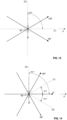
- the preform is formed of plies with different fiber orientations, the orientations being defined in a conventional manner with respect to a reference axis of the room.
- fiber orientations at ⁇ and ( ⁇ ⁇ 180°) are equivalent. Conventionally, fiber orientations are defined between +90° and -90° relative to the X axis, with fiber orientations at +90° and -90° being equivalent.
- the preform is formed from eight plies of fibers, according to the following stack: +45°/-45°/0°/90°/90°/0°/-45°/+45°.
- a felt 4 of non-woven filaments or fibers 40 is applied to a first main face 101a of the dry preform, and the preform thus provided with the felt is subjected to a needling operation, as illustrated schematically to the figure 4 , by passing through a needling device or needling machine 5.
- the needling machine known per se for consolidating layers of fibers, comprises a plurality of needles 8 mounted on a support 52 or needle board, capable of being animated, by appropriate means 53, with a moving movement. back and forth in a direction parallel to the needles.
- the needling machine comprises a perforated support table 54 arranged opposite the needles and intended to support the preform, as well as a stripper or stripper 55 placed between the support table and the needles, provided with through holes for the passage of the needles.
- the support table also includes a set of holes to allow the passage of the needles after they have passed through the preform.
- the needling machine is equipped here with so-called fork needles 8, of longitudinal axis A, as illustrated in Figures 5, 6A and 6B , each needle comprising at the end of its distal portion or working part 81 a notch 82, so that the needle drives the filaments only during the penetration phase, i.e. from top to bottom on the figure 4 .
- the notch 82 is defined between a bottom wall 83 and two side walls 84a, 84b and has an axis B, called the notch axis, arranged parallel to said walls 83, 84a, 84b, and perpendicular to the longitudinal axis A of the needle.
- the preform is driven positively in the direction of the arrow referenced F1, and the needles are driven back and forth.
- felt fibers are positioned in the notches 51b of the needles and are carried through the entire thickness of the preform, the filaments emerging on the second main face 101b, as illustrated schematically to the Figure 7 .
- the needling density is defined according to the frequency of the back and forth movement of the needles, the number of needles, and the speed of advancement of the preform in the needling machine.
- the needling is carried out so that the notch axes make a non-zero angle with the fiber orientations of the plies.
- all the needles are identical and mounted in the same way on the needle board, the notch axes of the needles having all the same orientation.
- the notch axes are oriented at +67.5° or -67.5°, for example at 67 .5° as illustrated on the figure 8 , in order to obtain a maximum angle between the notch axes and the oriented fibers at 0°, and thus limit as much as possible the risk of breakage of these fibers oriented at 0°.
- the orientation of the notch axes relative to the fiber orientations of the preform is for example obtained by appropriately orienting the preform entering a needling machine whose position is fixed.
- a lubricating agent also called lubricating agent
- the lubricating agent comprises water and is applied by a spray system to the preform.
- the water present in the preform as a lubricating agent reduces friction between the needles and thus reduces the heating of the preform, which guarantees efficient transfer of the felt filaments through the preform, limits fiber breakage, and allows any fibrils resulting from fiber breakage to be trapped in the preform.
- the preform is advantageously subjected to a drying operation in order to reduce the water content of the preform or remove any trace of water in the preform. This drying operation is for example carried out by placing the preform in an oven.
- the needling density and the penetration depth of the needles which is equal to the distance between the end of the needle and the second main face of the preform, are defined so that the preform presents a quantity of filaments, preferably similar, on each of its faces, these surface filaments increasing the permeability of the preform, and also facilitate the forming operation.
- the filaments are not applied in the form of a felt, but projected randomly onto the first face of the preform.
- the preform provided with needled filaments is then transferred to a press for the forming operation, also called stamping operation.
- the press 6 includes female forming tooling 61 or matrix, presenting a recess whose shape corresponds to that of the spherical cap 12 of the preform to be produced, and a male forming tool 62, or punch, comprising a boss of complementary shape.
- the forming is carried out by relative approximation of the male forming tooling and the female forming tooling, from an open position of the press illustrated in Figure 9 towards a closed position of the press illustrated in Figure 10 .
- the forming is carried out hot, the preform being at a forming temperature between the glass transition temperature and the melting temperature of the polymer constituting the binder, and between the glass transition temperature and the melting temperature of the polymer forming the filaments felt.
- This forming temperature of the preform is obtained by preheating the preform before positioning in the press and/or by heating the two tools 61, 62. This preheating is for example carried out by passing the initial preform between the upper infrared lamp bars. and lower part of a preheating oven or tunnel.
- the preform is held under tension by a tensioning system, for example of the blank holder type, as represented schematically under the reference 63.
- the tools 61, 62 are then moved aside. one from the other in the open position to be able to unmold the three-dimensional reinforced preform 301 from the press.
- the resulting three-dimensional reinforced preform 301 is then subjected to an operation of adding or impregnating an impregnating polymer, thermosetting or thermoplastic, by an injection and/or infusion process.
- the three-dimensional reinforced preform is for example placed in an injection mold 7, between the male part and the female part of said mold, an impregnation polymer is injected under pressure into the preform, according to an RTM (Resin Transfer) type process. Molding), or Gap-RTM, as schematically illustrated by the arrow referenced F2.
- the composite part 1 obtained at the end of this impregnation step can be subjected to a trimming operation.
- the needling machine is equipped with forked needles comprising several notches at its end.
- the needling machine is equipped with so-called barbed needles 108, such as as illustrated in Figure 12 , comprising along its distal portion or working portion 181 one or more notches, oriented towards the end of the needle, for example two notches 182a, 182b, arranged symmetrically on either side of the longitudinal axis , and whose notch axes are arranged parallel.
- the notch axes B are preferably arranged so that the angle with the reference axis is maximum, or along the second 90° bisector.
- the notch axes B are preferably arranged so that the angle with the reference axis is maximum, or along the bisector C3 at 90°.
Landscapes
- Engineering & Computer Science (AREA)
- Mechanical Engineering (AREA)
- Textile Engineering (AREA)
- Chemical & Material Sciences (AREA)
- Composite Materials (AREA)
- Nonwoven Fabrics (AREA)
- Laminated Bodies (AREA)
- Treatment Of Fiber Materials (AREA)
- Reinforced Plastic Materials (AREA)
Claims (12)
- Verfahren zur Herstellung eines Teils (1) aus Verbundwerkstoff, umfassend fortlaufende Fasern und eine Polymer-Matrix, wobei das Verfahren umfasst- einen Schritt zur Herstellung einer Vorform (101), die aus fortlaufenden unidirektionalen Fasern gebildet wird, die entlang mindestens einer Faserausrichtung ausgerichtet sind,- einen Schritt des Auftragens von Vliesfilamenten (40) auf mindestens einer ersten Hauptfläche (1001a) der Vorform, und- einen Schritt des Vernadelns der Filamente anhand einer Vernadelungsvorrichtung (5), die eine Vielzahl von Nadeln (8, 108) umfasst, von denen jede mit mindestens einer Kerbe versehen ist, sodass Filamente durch die Nadeln angetrieben werden, und in einer im Wesentlichen senkrechten Richtung zu den fortlaufenden Fasern der Vorform angeordnet werden,dadurch gekennzeichnet, dass beim Vernadelungsschritt jede Nadel mit einer einzigen Kerbe (82), die sich entlang einer Kerbenachse (B) senkrecht zur Hauptlängsachse (A) der Nadel erstreckt, oder mehreren Kerben (182a, 182b) versehen ist, die sich jeweils entlang einer Kerbenachse senkrecht zur Hauptlängsachse der Nadel erstrecken, wobei die Kerbenachsen zueinander parallel sind, die Nadeln und die Vorform derart angeordnet sind, dass die Kerbenachsen einen Winkel ungleich null mit der oder den Faserausrichtungen bilden.
- Verfahren nach Anspruch 1, dadurch gekennzeichnet, dass die Vorform (101) aus mehreren überlagerten Falten (111-114) gebildet ist, wobei jede Falte aus fortlaufenden unidirektionalen Fasern gebildet ist, die entlang einer Faserausrichtung ausgerichtet sind, wobei die Vorform Falten umfasst, die mindestens zwei unterschiedliche Faserausrichtungen aufweisen, wobei die Nadeln und die Vorform derart angeordnet sind, dass die Kerbenachsen beim Vernadeln mit jeder der beiden Faserausrichtungen einen Winkel ungleich null bilden.
- Verfahren nach Anspruch 2, dadurch gekennzeichnet, dass die Vorform (101) Falten mit unterschiedlichen Faserausrichtungen umfasst, wobei die Kerbenachsen (B) beim Vernadeln mit jeder Faserausrichtung einen Winkel ungleich null bilden.
- Verfahren nach Anspruch 2 oder 3, dadurch gekennzeichnet, dass die Kerbenachsen (B) im Wesentlichen entlang einer Halbierungslinie (C1-C4) zweier benachbarter Faserausrichtungen, um mehr oder weniger als 10°, vorzugsweise mehr oder weniger als 5°, besser noch um mehr oder weniger als 2,5° angeordnet sind.
- Verfahren nach einem der Ansprüche 1 bis 4, dadurch gekennzeichnet, dass die Faserausrichtungen zwischen +90° und -90° um eine Bezugsachse (X) herum definiert sind, wobei die Kerbenachsen entlang einer Ausrichtung ausgerichtet sind, die am weitesten von der Bezugsachse entfernt ist.
- Verfahren nach einem der Ansprüche 1 bis 5, dadurch gekennzeichnet, dass die Kerbenachsen (B) einen Winkel von mindestens 15° mit jeder Faserausrichtung, vorzugsweise von mindestens 22,5° bilden.
- Verfahren nach einem der Ansprüche 1 bis 6, dadurch gekennzeichnet, dass die Vernadelung anhand von Kranznadeln (8) hergestellt wird, die an ihrem distalen Ende mindestens eine Kerbe (82) aufweisen.
- Verfahren nach einem der Ansprüche 1 bis 7, dadurch gekennzeichnet, dass die Vorform gebildet wird- aus Falten mit Faserausrichtungen bei 0° und 90° in Bezug auf eine Bezugsachse (X), wobei die Kerbenachsen bei +45° und/oder -45°, vorzugsweise +45° oder -45° von der Bezugsachse angeordnet sind; oder- aus Falten mit Faserausrichtungen bei +30° und -30° in Bezug auf eine Bezugsachse (X), wobei die Kerbenachsen bei 0° oder 90°, vorzugsweise bei 90° von der Bezugsachse angeordnet sind; oder- aus Falten mit Faserausrichtungen bei 0°, 90°, +45° und -45° in Bezug auf eine Bezugsachse (X), wobei die Kerbenachsen bei +22,5°, -22,5°, +67,5° und/oder -67,5°, vorzugsweise bei +67,5° und/oder -67,5°, besser noch bei +67,5° oder -67,5° von der Bezugsachse angeordnet sind; oder- aus Falten mit Faserausrichtungen bei 0°, +60° und -60° in Bezug auf eine Bezugsachse (X), wobei die Kerbenachsen bei 90°, +30°, oder -30°, vorzugsweise bei 90° von der Bezugsachse angeordnet sind, oder- aus Falten mit Faserausrichtungen bei 0°, +30° und -30° in Bezug auf eine Bezugsachse (X), wobei die Kerbenachsen bei 90° von der Bezugsachse angeordnet sind.
- Verfahren nach einem der Ansprüche 1 bis 8, dadurch gekennzeichnet, dass die Vorform beim Vernadeln ein Schmiermittel zum Verringern der Reibungen zwischen den Nadeln und den Fasern der Vorform umfasst.
- Verfahren nach einem der Ansprüche 1 bis 9, dadurch gekennzeichnet, dass es die Herstellung einer trockenen Vorform umfasst, die mehrere überlagerte Falten umfasst, wobei die Falten aus fortlaufenden trockenen Fasern gebildet sind, die mit einem Bindemittel versehen sind, wobei das Bindemittel ein erstes Polymer umfasst, wobei das Verfahren nach dem Vernadelungsschritt einen Imprägnierungsschritt der trockenen Vorform mit einem Imprägnierungspolymer umfasst, das die Polymer-Matrix bildet.
- Verfahren nach einem der Ansprüche 1 bis 10, dadurch gekennzeichnet, dass der Schritt des Auftragens von Filamenten (40) das Auftragen eines Vliesfilzes (4) umfasst, der aus den Filamenten gebildet ist.
- Verfahren nach einem der Ansprüche 1 bis 11, dadurch gekennzeichnet, dass die Herstellung der Vorform die Herstellung von überlagerten Falten durch Kontaktauftragung, anhand einer Auftragungsrolle (32) von fortlaufenden Fasern auf einem Drapierwerkzeug (2) umfasst, wobei jede Falte durch Auftragen eines oder mehrerer Bänder entlang einer Ausrichtung auf dem Drapierwerkzeug oder auf Bändern der vorherigen Falte hergestellt wird, wobei jedes Band aus einer oder mehreren fortlaufenden Fasern gebildet ist.
Applications Claiming Priority (2)
| Application Number | Priority Date | Filing Date | Title |
|---|---|---|---|
| FR1770898A FR3070623B1 (fr) | 2017-09-04 | 2017-09-04 | Procede de realisation d’une piece en materiau composite par aiguilletage oriente d’une preforme |
| PCT/FR2018/000205 WO2019043302A1 (fr) | 2017-09-04 | 2018-08-14 | Procédé de réalisation d'une pièce en matériau composite par aiguilletage orienté d'une préforme |
Publications (2)
| Publication Number | Publication Date |
|---|---|
| EP3678850A1 EP3678850A1 (de) | 2020-07-15 |
| EP3678850B1 true EP3678850B1 (de) | 2023-11-29 |
Family
ID=60450950
Family Applications (1)
| Application Number | Title | Priority Date | Filing Date |
|---|---|---|---|
| EP18762344.2A Active EP3678850B1 (de) | 2017-09-04 | 2018-08-14 | Verfahren zur herstellung eines verbundwerkstoffteils durch orientiertes vernadeln einer vorform |
Country Status (6)
| Country | Link |
|---|---|
| US (1) | US12343944B2 (de) |
| EP (1) | EP3678850B1 (de) |
| JP (1) | JP7329852B2 (de) |
| ES (1) | ES2971469T3 (de) |
| FR (1) | FR3070623B1 (de) |
| WO (1) | WO2019043302A1 (de) |
Families Citing this family (5)
| Publication number | Priority date | Publication date | Assignee | Title |
|---|---|---|---|---|
| FR3056438B1 (fr) | 2016-09-27 | 2019-11-01 | Coriolis Group | Procede de realisation de pieces en materiau composite par impregnation d'une preforme particuliere. |
| FR3101276B1 (fr) * | 2019-10-01 | 2022-12-30 | Coriolis Group | Procédé de réalisation d’une pièce en materiau composite de type sandwich par aiguilletage |
| DE102021203391A1 (de) * | 2021-04-06 | 2022-10-06 | Fraunhofer-Gesellschaft zur Förderung der angewandten Forschung eingetragener Verein | Verfahren zur Herstellung von offenporösen Knochenimplantaten aus Fasern, mit frei zugänglichen Leitstrukturen aus Fasern, die aus einem biokompatiblen Metall oder Metalllegierung gebildet sind |
| IT202100029546A1 (it) * | 2021-11-23 | 2023-05-23 | Brembo Sgl Carbon Ceram Brakes S P A | Metodo per realizzare una preforma fibrosa in carbonio e/o fibre di un precursore del carbonio di altezza predeterminata e preforma direttamente ottenuta |
| US20250146550A1 (en) * | 2023-11-08 | 2025-05-08 | Honeywell International Inc. | Composite preforms |
Family Cites Families (161)
| Publication number | Priority date | Publication date | Assignee | Title |
|---|---|---|---|---|
| US494910A (en) | 1893-04-04 | Brake for baby-carriages | ||
| US1100829A (en) | 1911-04-07 | 1914-06-23 | Goodrich Co B F | Hose construction. |
| US1164303A (en) | 1913-03-21 | 1915-12-14 | Edward S Nicewarner | Laminated tube. |
| US1301354A (en) | 1917-07-11 | 1919-04-22 | Cassius M Clay Baird | Hose construction. |
| US3206429A (en) | 1961-05-17 | 1965-09-14 | Eastman Kodak Co | Antistatic polyethylene compositions containing n,n-diethanol oleamide |
| US3238084A (en) | 1962-07-06 | 1966-03-01 | Union Carbide Corp | Device for manufacturing reinforced plastic material |
| US3300355A (en) | 1963-06-20 | 1967-01-24 | William E Adams | Method of making irregularly shaped hollow plastic bodies |
| US3265795A (en) | 1964-05-25 | 1966-08-09 | Koppers Co Inc | Method of skin molding |
| DE1922327U (de) | 1965-05-05 | 1965-08-26 | Kalle Ag | Querschneider fuer papier und folien. |
| US3729785A (en) * | 1967-04-04 | 1973-05-01 | Sommer Sa Soc | Textile, web needling device |
| FR1590718A (de) | 1968-10-10 | 1970-04-20 | ||
| US3563122A (en) | 1969-05-22 | 1971-02-16 | Minnesota Mining & Mfg | Tape dispensing apparatus |
| DE2032283A1 (de) | 1969-07-04 | 1971-03-25 | Hawker Siddeley Aviation Ltd , King ston upon Thames, Surrey (Großbritannien) | Groß Tragwerk, insbesondere Haupt bauteil eines Flugzeugs |
| US3692601A (en) | 1970-07-27 | 1972-09-19 | Goldworthy Eng Inc | Method for making a storage tank by applying continuous filaments to the interior surface of a rotating mold |
| US3662821A (en) | 1971-02-01 | 1972-05-16 | Daniel I Saxon | Heat transfer roll with separate temperature zones for processing materials |
| US3713572A (en) | 1971-02-03 | 1973-01-30 | Goldsworthy Eng Inc | Material feeding system |
| US3856052A (en) | 1972-07-31 | 1974-12-24 | Goodyear Tire & Rubber | Hose structure |
| FR2254428A1 (en) | 1973-12-13 | 1975-07-11 | Fiber Science Inc | Rotor or aircraft wing structure - has wound wire tubular longitudinal components encloseesed in cladding surface |
| US4118814A (en) | 1975-11-17 | 1978-10-10 | Gerald Herbert Holtom | Manufacture of boat hulls and other hollow articles |
| US4234374A (en) | 1978-10-10 | 1980-11-18 | The Boeing Company | Bi-directional step-over tape applicator head |
| US4259144A (en) | 1978-10-10 | 1981-03-31 | The Boeing Company | Bi-directional tape applicator head and method |
| US4242160A (en) | 1979-02-02 | 1980-12-30 | United Technologies Corporation | Method of winding a wind turbine blade using a filament reinforced mandrel |
| US4351588A (en) | 1979-04-24 | 1982-09-28 | Relium Ag | Process and means for controlling the radiant energies of the entire spectral range in rooms |
| US4309800A (en) | 1979-08-02 | 1982-01-12 | Foster Needle Co. | Felting needle |
| US4735672A (en) | 1982-05-27 | 1988-04-05 | Lockheed Corporation | Automated fiber lay-up machine |
| GB2124130B (en) | 1982-07-24 | 1985-11-27 | Rolls Royce | Vacuum moulding fibre reinforced resin |
| US4488466A (en) | 1982-09-07 | 1984-12-18 | Seal Tech Corp. | Apparatus for cutting sheet material |
| US4976012A (en) | 1982-11-29 | 1990-12-11 | E. I Du Pont De Nemours And Company | Method of forming a web |
| DE3371897D1 (en) | 1983-01-14 | 1987-07-09 | Boeing Co | Bi-directional applicator head with dual tape supply |
| US4461669A (en) | 1983-09-30 | 1984-07-24 | The Boeing Company | Pivotal mount for laminating head |
| DE3341564A1 (de) | 1983-11-17 | 1985-05-30 | Messerschmitt-Bölkow-Blohm GmbH, 8012 Ottobrunn | Gekruemmtes flaechenbauteil, insbesondere fuer luftfahrzeuge und vorrichtung zu deren herstellung |
| US4569716A (en) | 1984-03-05 | 1986-02-11 | Cincinnati Milacron Inc. | Strand laying head |
| US4574029A (en) | 1984-04-27 | 1986-03-04 | Ltv Aerospace And Defense Company | Apparatus for forming concave tape wrapped composite structures |
| US4714509A (en) | 1984-07-02 | 1987-12-22 | E. I. Dupont De Nemours And Company | Method and apparatus for laying down tapes |
| US4522876A (en) * | 1984-07-05 | 1985-06-11 | Lydall, Inc. | Integral textile composite fabric |
| US4752515A (en) * | 1985-06-17 | 1988-06-21 | Mitsubishi Chemical Industries | Alumina fiber structure |
| FR2587318B1 (fr) | 1985-09-18 | 1987-10-30 | Commissariat Energie Atomique | Procede et machine pour la fabrication de pieces creuses de revolution formees de fils s'etendant selon trois directions differentes. |
| US5388320A (en) | 1987-01-27 | 1995-02-14 | Aerospace Preforms Limited | Production of shaped filamentary structures |
| US4699031A (en) | 1986-02-20 | 1987-10-13 | Ametek, Inc. | Method and apparatus for automatically cutting a web of foam material into sheets and for dispensing the cut sheets |
| ES2018683B3 (es) | 1986-04-07 | 1991-05-01 | Hercules Inc | Sistema de bobinado de filamento |
| US4707212A (en) | 1986-04-28 | 1987-11-17 | The United States Of America As Represented By The Secretary Of The Air Force | Automated tape laying machine for composite structures |
| DE3614365A1 (de) | 1986-04-28 | 1987-10-29 | Messerschmitt Boelkow Blohm | Vorrichtung zum ablegen eines vorimpraegnierten faserbandes |
| JPS63173625A (ja) | 1987-01-13 | 1988-07-18 | Nitto Boseki Co Ltd | 繊維強化樹脂筒の製造方法 |
| US4881998A (en) | 1987-01-23 | 1989-11-21 | Morton Thiokol, Inc. | Radiation gathering reflector and method of manufacture |
| US4815660A (en) | 1987-06-16 | 1989-03-28 | Nordson Corporation | Method and apparatus for spraying hot melt adhesive elongated fibers in spiral patterns by two or more side-by-side spray devices |
| DE3743485A1 (de) | 1987-12-22 | 1989-07-13 | Mtu Muenchen Gmbh | Verfahren zur herstellung eines raeumlich verwundenen rotorschaufelblattes |
| JPH01281247A (ja) | 1988-05-07 | 1989-11-13 | Shin Nippon Koki Kk | テープの自動貼付装置におけるテープの張力制御装置 |
| US4992133A (en) | 1988-09-30 | 1991-02-12 | Pda Engineering | Apparatus for processing composite materials |
| US4990213A (en) | 1988-11-29 | 1991-02-05 | Northrop Corporation | Automated tape laminator head for thermoplastic matrix composite material |
| US5015326A (en) | 1989-05-08 | 1991-05-14 | The Boeing Company | Compliant tape dispensing and compacting head |
| US5110395A (en) | 1989-12-04 | 1992-05-05 | Cincinnati Milacron Inc. | Fiber placement head |
| US5087187A (en) | 1990-03-09 | 1992-02-11 | United Technologies Corporation | Apparatus for molding hollow composite articles having internal reinforcement structures |
| FR2660238B1 (fr) | 1990-04-02 | 1992-07-03 | Ceca Sa | Procede perfectionne pour l'obtention de blocs d'autoadhesifs thermofusibles a surface non collante, blocs d'autoadhesifs thermofusibles obtenus par ce procede. |
| US5078592A (en) | 1990-04-09 | 1992-01-07 | Grimshaw Michael N | Heating system for composite tape |
| AT394216B (de) * | 1990-07-02 | 1992-02-25 | Polyfelt Gmbh | Verfahren zur herstellung von vernadelten spinnvliesen |
| DE69125941D1 (de) | 1990-08-31 | 1997-06-05 | Aerospace Preforms Ltd | Formteilherstellung aus filament |
| US5216790A (en) * | 1990-10-26 | 1993-06-08 | Milliken Research Corporation | Needled nonwoven fabric |
| CA2057201C (en) | 1990-12-19 | 1998-05-19 | Vernon M. Benson | Multiple axes fiber placement machine |
| US5200018A (en) | 1990-12-19 | 1993-04-06 | Hercules Incorporated | Ribbonizing apparatus for individually heating a plurality of laterally adjacent tows in a fiber placement device |
| CA2057222C (en) | 1990-12-19 | 1998-05-19 | Keith G. Shupe | Fiber placement delivery system |
| FR2686907B1 (fr) | 1992-02-05 | 1996-04-05 | Europ Propulsion | Procede d'elaboration de preformes fibreuses pour la fabrication de pieces en materiaux composites et produits obtenus par le procede. |
| FR2686080B1 (fr) | 1992-01-14 | 1994-11-10 | Aerospatiale | Procede de depose au contact a chaud de materiau composite fibre a matrice vitreuse et dispositif pour la mise en óoeuvre du procede. |
| FR2687389B1 (fr) | 1992-02-17 | 1994-05-06 | Aerospatiale Ste Nationale Indle | Dispositif et procede pour realiser une piece de structure complexe par depose au contact de fil ou ruban. |
| GB2268704B (en) | 1992-07-16 | 1996-01-10 | British Aerospace | Layup preparation for fibre reinforced composites |
| GB2270672B (en) | 1992-09-02 | 1995-10-25 | Ferodo Caernarfon Ltd | Fabrication of friction elements |
| FR2701665B1 (fr) * | 1993-02-17 | 1995-05-19 | Europ Propulsion | Procédé de fabrication d'une pièce en matériau composite, notamment un panneau sandwich, à partir de plusieurs préformes assemblées. |
| GB9309305D0 (en) | 1993-05-06 | 1993-06-16 | Smith Colin P | Creel |
| FR2705655B1 (fr) | 1993-05-26 | 1995-08-25 | Aerospatiale | Machine pour le bobinage-déposé au contact simultané d'une pluralité de fils individuels. |
| US5397523A (en) | 1993-07-20 | 1995-03-14 | Cincinnati Mliacron Inc. | Method and apparatus for sizing composite tows |
| US5469686A (en) | 1993-09-27 | 1995-11-28 | Rockwell International Corp. | Composite structural truss element |
| WO1995020104A1 (en) | 1994-01-20 | 1995-07-27 | Torres Martinez, Manuel | Fabrication of aerodynamic profiles |
| DE4422002C2 (de) | 1994-06-23 | 1999-04-15 | Dornier Gmbh | Vorrichtung zur maschninellen Ablage von nassimprägnierten endlosen Fasersträngen auf beliebig gekrümmten Flächen oder Flächenabschnitten |
| US5447586A (en) | 1994-07-12 | 1995-09-05 | E. I. Du Pont De Nemours And Company | Control of thermoplastic tow placement |
| US5515585A (en) | 1994-07-25 | 1996-05-14 | The Bf Goodrich Company | Process for forming needled fibrous structures using determined transport depth |
| US5858890A (en) * | 1994-07-25 | 1999-01-12 | The B. F. Goodrich Company | Laminar fibrous structure having Z-fibers that penetrate a constant number of layers |
| GB2292365B (en) | 1994-08-15 | 1996-11-27 | Nitta Corp | Automatic tool changer |
| US5587041A (en) | 1995-03-21 | 1996-12-24 | The United States Of America As Represented By The Administrator Of The National Aeronautics And Space Administration | Composite prepreg application device |
| IT1280200B1 (it) | 1995-07-14 | 1998-01-05 | Pilosio Spa | Procedimento di produzione in continuo di tavole sandwich e relativo impianto |
| US5700347A (en) | 1996-01-11 | 1997-12-23 | The Boeing Company | Thermoplastic multi-tape application head |
| US5876540A (en) * | 1996-05-31 | 1999-03-02 | The Boeing Company | Joining composites using Z-pinned precured strips |
| US5766357A (en) | 1996-09-19 | 1998-06-16 | Alliant Techsystems Inc. | Apparatus for fiber impregnation |
| FR2761380B1 (fr) | 1997-03-28 | 1999-07-02 | Europ Propulsion | Procede et machine pour la realisation de nappes fibreuses multiaxiales |
| US5979531A (en) | 1997-10-01 | 1999-11-09 | Mcdonnell Douglas Corporation | Bi-directional fiber placement head |
| US6073670A (en) | 1997-10-31 | 2000-06-13 | Isogrid Composites, Inc. | Multiple fiber placement head arrangement for placing fibers into channels of a mold |
| FR2774325B1 (fr) | 1998-02-05 | 2000-03-17 | Alexandre Hamlyn | Procede de fabrication de corps flottants et embarcations nautiques mandrins et appareils pour cette fabrication |
| US6026883A (en) | 1998-04-30 | 2000-02-22 | Alliant Techsystems, Inc. | Self-contained apparatus for fiber element placement |
| US6458309B1 (en) | 1998-06-01 | 2002-10-01 | Rohr, Inc. | Method for fabricating an advanced composite aerostructure article having an integral co-cured fly away hollow mandrel |
| FR2784930B1 (fr) | 1998-10-23 | 2007-09-28 | Vetrotex France Sa | Corps de revolution creux en materiau composite et son procede de fabrication |
| FR2785623B1 (fr) | 1998-11-10 | 2001-01-26 | Aerospatiale | Procede et dispositif de depose au contact de fils de fibres pre-impregnees notamment pour la realisation de structures complexes en materiau composite polymerise par ionisation |
| US6256889B1 (en) | 1998-12-23 | 2001-07-10 | Michigan Tool Design | Auto glass replacement tool |
| ATE311492T1 (de) | 1999-01-12 | 2005-12-15 | Hunter Douglas | Faservlies |
| JP4491968B2 (ja) | 1999-03-23 | 2010-06-30 | 東レ株式会社 | 複合炭素繊維基材、プリフォームおよび炭素繊維強化プラスチックの製造方法 |
| US6251185B1 (en) | 1999-04-02 | 2001-06-26 | Molded Fiber Glass Companies | System for delivering chopped fiberglass strands to a preform screen |
| US6889937B2 (en) | 1999-11-18 | 2005-05-10 | Rocky Mountain Composites, Inc. | Single piece co-cure composite wing |
| US6451152B1 (en) | 2000-05-24 | 2002-09-17 | The Boeing Company | Method for heating and controlling temperature of composite material during automated placement |
| DE10037773C1 (de) | 2000-08-03 | 2002-08-22 | Hennecke Gmbh | Verfahren und Vorrichtung zum Herstellen von mit Langfasern verstärkten Kunststoff-Formteilen |
| EP1199161A1 (de) | 2000-10-20 | 2002-04-24 | SOLVAY POLYOLEFINS EUROPE - BELGIUM (Société Anonyme) | Rohr aus Polyethylen |
| US6527533B2 (en) | 2000-12-29 | 2003-03-04 | Ford Global Technologies, Inc. | Processing systems for automated manufacture of preforms |
| US7124797B2 (en) | 2001-03-02 | 2006-10-24 | Toyota Motor Sales, Usa, Inc. | Filament winding apparatus and methods of winding filament |
| US7105071B2 (en) | 2001-04-06 | 2006-09-12 | Ebert Composites Corporation | Method of inserting z-axis reinforcing fibers into a composite laminate |
| US6772663B2 (en) | 2001-04-20 | 2004-08-10 | Tamarack Products, Inc. | Apparatus and method for rotary pressure cutting |
| FR2831479B1 (fr) | 2001-10-26 | 2004-01-02 | Coriolis Composites | Procede de fabrication de profils presentant un etat de surface specifique en resines synthetiques renforcees par des fibres et machine pour mettre en oeuvre le procede |
| US6755103B2 (en) | 2002-02-08 | 2004-06-29 | Wilson Tool International, Inc. | Ball-lock insert assemblies |
| ES2212878B1 (es) | 2002-03-05 | 2005-07-16 | Manuel Torres Martinez | Cabezal multiaplicador de tiras de fibra. |
| US6729576B2 (en) | 2002-08-13 | 2004-05-04 | Sikorsky Aircraft Corporation | Composite tail cone assembly |
| CN100509385C (zh) * | 2002-11-01 | 2009-07-08 | 贝尔直升机泰克斯特龙公司 | 用于复合叠层板z方向加固的方法和设备 |
| US8336596B2 (en) | 2002-11-22 | 2012-12-25 | The Boeing Company | Composite lamination using array of parallel material dispensing heads |
| US7093638B2 (en) | 2003-04-21 | 2006-08-22 | Lignum Vitae Limited | Apparatus and method for manufacture and use of composite fiber components |
| JP2005007252A (ja) | 2003-06-17 | 2005-01-13 | Tatsumi Nakazawa | 塗布装置 |
| US7080441B2 (en) | 2003-07-28 | 2006-07-25 | The Boeing Company | Composite fuselage machine and method of automated composite lay up |
| US7083698B2 (en) | 2003-08-22 | 2006-08-01 | The Boeing Company | Automated composite lay-up to an internal fuselage mandrel |
| US7048024B2 (en) | 2003-08-22 | 2006-05-23 | The Boeing Company | Unidirectional, multi-head fiber placement |
| US7293590B2 (en) | 2003-09-22 | 2007-11-13 | Adc Acquisition Company | Multiple tape laying apparatus and method |
| FR2862987B1 (fr) | 2003-11-28 | 2006-09-22 | Saint Gobain Vetrotex | Mat de verre aiguillette |
| FR2865156B1 (fr) | 2004-01-19 | 2006-11-10 | Dcmp | Dispositif de depose de nappe ou de fils dans un moule pour la fabrication de pieces en materiaux composites |
| CA2563640A1 (en) | 2004-04-21 | 2005-11-10 | Ingersoll Machine Tools, Inc. | Forming a composite structure by filament placement on a tool surface of a tablet |
| US7761964B2 (en) * | 2004-05-13 | 2010-07-27 | Groz-Beckert Kg | Structuring needle for treating fiber webs |
| JP2005329593A (ja) | 2004-05-19 | 2005-12-02 | Fuji Heavy Ind Ltd | 自動積層装置 |
| US20060118244A1 (en) | 2004-12-02 | 2006-06-08 | The Boeing Company | Device for laying tape materials for aerospace applications |
| DK176564B1 (da) * | 2004-12-29 | 2008-09-01 | Lm Glasfiber As | Fiberforstærket samling |
| US7472736B2 (en) | 2005-02-14 | 2009-01-06 | The Boeing Company | Modular head lamination device and method |
| FR2882681B1 (fr) | 2005-03-03 | 2009-11-20 | Coriolis Composites | Tete d'application de fibres et machine correspondante |
| US7410352B2 (en) | 2005-04-13 | 2008-08-12 | The Boeing Company | Multi-ring system for fuselage barrel formation |
| US20070044896A1 (en) | 2005-08-25 | 2007-03-01 | Ingersoll Machine Tools, Inc. | Auto-splice apparatus and method for a fiber placement machine |
| DE602006011403D1 (de) | 2005-08-25 | 2010-02-11 | Ingersoll Machine Tools Inc | Kompakte Faserauflegevorrichtung |
| US7810539B2 (en) | 2005-08-25 | 2010-10-12 | Ingersoll Machine Tools, Inc. | Compaction roller for a fiber placement machine |
| US20080093026A1 (en) | 2006-10-24 | 2008-04-24 | Niko Naumann | Device for pressing a tape |
| US7735779B2 (en) | 2006-11-02 | 2010-06-15 | The Boeing Company | Optimized fuselage structure |
| US7993124B2 (en) | 2006-12-28 | 2011-08-09 | The Boeing Company | Heating apparatus for a composite laminator and method |
| FR2912680B1 (fr) | 2007-02-21 | 2009-04-24 | Coriolis Composites Sa | Procede et dispositif de fabrication de pieces en materiau composite, en particulier de troncons de fuselage d'avion |
| DE102007009124B4 (de) | 2007-02-24 | 2011-11-03 | Evonik Degussa Gmbh | Induktionsgestützte Fertigungsverfahren |
| FR2912953B1 (fr) | 2007-02-28 | 2009-04-17 | Coriolis Composites Sa | Machine d'application de fibres avec tubes flexibles d'acheminement de fibres |
| FR2913366B1 (fr) | 2007-03-06 | 2009-05-01 | Coriolis Composites Sa | Tete d'application de fibres avec systemes de coupe et de blocage de fibres particuliers |
| FR2913365B1 (fr) | 2007-03-06 | 2013-07-26 | Coriolis Composites Attn Olivier Bouroullec | Tete d'application de fibres avec systemes de coupe de fibres particuliers |
| FR2915925B1 (fr) | 2007-05-10 | 2013-02-22 | Coriolis Composites Attn Olivier Bouroullec | Machine d'application de fibres avec systeme de changement d'outils |
| US7717151B2 (en) | 2007-11-29 | 2010-05-18 | Spirit Aerosystems, Inc. | Material placement method and apparatus |
| JP5308355B2 (ja) | 2007-12-25 | 2013-10-09 | 株式会社住軽伸銅 | レベルワウンドコイルの巻解方法 |
| US8074330B2 (en) * | 2008-08-13 | 2011-12-13 | Goodrich Corporation | Method and system for enabling z fiber transfer in needled preform |
| FR2937582B1 (fr) | 2008-10-28 | 2010-12-17 | Coriolis Composites | Machine d'application de fibres avec tubes flexibles d'acheminement de fibres places dans une gaine froide |
| FR2943943A1 (fr) | 2009-04-02 | 2010-10-08 | Coriolis Composites | Procede et machine pour l'application d'une bande de fibres sur des surfaces convexes et/ou avec aretes |
| FR2948058B1 (fr) | 2009-07-17 | 2011-07-22 | Coriolis Composites | Machine d'application de fibres comprenant un rouleau de compactage souple avec systeme de regulation thermique |
| FR2948059B1 (fr) | 2009-07-17 | 2011-08-05 | Coriolis Composites | Machine d'application de fibres avec rouleau de compactage transparent au rayonnement du systeme de chauffage |
| FR2975335B1 (fr) | 2011-05-20 | 2013-05-17 | Coriolis Composites Attn Olivier Bouroullec | Machine d'application de fibres avec tubes flexibles d'acheminement de fibres munis de lames flexibles |
| WO2013030467A1 (fr) | 2011-09-02 | 2013-03-07 | Coriolis Composites | Tete d'application de fibres avec peigne a languettes flexibles |
| FR2982793B1 (fr) | 2011-11-18 | 2019-06-28 | Coriolis Group | Tete d'application de fibres bi-directionnelle |
| DE102012007439A1 (de) | 2012-04-13 | 2013-10-17 | Compositence Gmbh | Legekopf und Vorrichtung und Verfahren zum Aufbau eines dreidimensionalen Vorformlings für ein Bauteil aus einem Faserverbundwerkstoff |
| FR2999466B1 (fr) | 2012-12-18 | 2015-06-19 | Airbus Operations Sas | Machine de placement de fibres comprenant un rouleau avec des bagues pivotantes |
| FR2999973B1 (fr) | 2012-12-21 | 2015-04-10 | Coriolis Composites | Procede de realisation de preformes a partir de fibres munies d'un liant et machine correspondante |
| DE102013103039A1 (de) | 2013-03-25 | 2014-09-25 | Dieffenbacher GmbH Maschinen- und Anlagenbau | Verfahren, Vorrichtung und Vorformling zur mehrstufigen Herstellung eines dreidimensionalen Vorformlings im Zuge der Herstellung von faserverstärkten Formteilen |
| FR3006938B1 (fr) | 2013-06-18 | 2015-10-02 | Coriolis Composites | Tete d application de fibres bi directionnelle a deux rouleaux |
| FR3009510B1 (fr) | 2013-08-06 | 2016-01-01 | Astrium Sas | Tete de depose de fils pour la realisation de pieces en materiau composite |
| FR3016827B1 (fr) | 2014-01-24 | 2016-02-05 | Coriolis Composites | Procede de realisation de preformes a partir de fibres avec application en ligne d'un liant, et machine correspondante |
| FR3033729B1 (fr) | 2015-03-16 | 2017-10-06 | Coriolis Composites | Tete d'application de fibres avec systeme de chauffage infrarouge |
| FR3034338B1 (fr) | 2015-04-01 | 2017-04-21 | Coriolis Composites | Tete d'application de fibres avec rouleau d'application particulier |
| FR3043010B1 (fr) | 2015-10-28 | 2017-10-27 | Coriolis Composites | Machine d'application de fibres avec systemes de coupe particuliers |
| FR3048373B1 (fr) | 2016-03-07 | 2018-05-18 | Coriolis Group | Procede de realisation de preformes avec application d'un liant sur fibre seche et machine correspondante |
| US9856592B2 (en) * | 2016-03-15 | 2018-01-02 | Goodrich Corporation | Methods and systems for forming a fibrous preform |
| FR3056438B1 (fr) * | 2016-09-27 | 2019-11-01 | Coriolis Group | Procede de realisation de pieces en materiau composite par impregnation d'une preforme particuliere. |
| US20180093446A1 (en) * | 2016-09-30 | 2018-04-05 | The Boeing Company | Non-crimp fabric and method of manufacturing |
| FR3064524B1 (fr) | 2017-04-03 | 2019-04-05 | Coriolis Group | Procede et realisation de pieces en materiaux composite a partir de preformes aiguilletees en presence d'agent lubrifiant. |
| FR3064523B1 (fr) | 2017-04-03 | 2020-07-17 | Coriolis Group | Procede de realisation de pieces en materiau composite a partir de preformes aiguilletees |
-
2017
- 2017-09-04 FR FR1770898A patent/FR3070623B1/fr not_active Expired - Fee Related
-
2018
- 2018-08-14 ES ES18762344T patent/ES2971469T3/es active Active
- 2018-08-14 EP EP18762344.2A patent/EP3678850B1/de active Active
- 2018-08-14 WO PCT/FR2018/000205 patent/WO2019043302A1/fr not_active Ceased
- 2018-08-14 US US16/644,097 patent/US12343944B2/en active Active
- 2018-08-14 JP JP2020512844A patent/JP7329852B2/ja active Active
Also Published As
| Publication number | Publication date |
|---|---|
| US12343944B2 (en) | 2025-07-01 |
| FR3070623B1 (fr) | 2020-10-09 |
| JP2020532447A (ja) | 2020-11-12 |
| FR3070623A1 (fr) | 2019-03-08 |
| WO2019043302A1 (fr) | 2019-03-07 |
| JP7329852B2 (ja) | 2023-08-21 |
| ES2971469T3 (es) | 2024-06-05 |
| US20200189207A1 (en) | 2020-06-18 |
| EP3678850A1 (de) | 2020-07-15 |
Similar Documents
| Publication | Publication Date | Title |
|---|---|---|
| EP3519166B1 (de) | Verfahren zur herstellung von verbundstoffmaterialteilen durch imprägnierung einer spezifischen vorform | |
| EP3678850B1 (de) | Verfahren zur herstellung eines verbundwerkstoffteils durch orientiertes vernadeln einer vorform | |
| EP2919969B1 (de) | Verfahren zum aufbringen eines zwischenmaterials unter gewährleistung deren kohäsion und zwischenmaterial | |
| EP2516138B1 (de) | Neue verbundmaterialien mit ineinander greifenden bändern | |
| EP3426452B1 (de) | Verfahren zur herstellung von vorformlingen mit anwendung eines bindemittels auf trockener faser und entsprechende maschine | |
| EP3606734B1 (de) | Verfahren zur herstellung von verbundstoffteilen aus in gegenwart eines schmiermittels genadelten vorformen | |
| EP3277486A1 (de) | Faserauftragskopf mit spezieller auftragsrolle | |
| EP3774305B1 (de) | Verfahren zur herstellung eines teils aus einem verbundwerkstoff durch vernadeln von untermengen von lagen | |
| EP3606735A1 (de) | Verfahren zur herstellung von verbundstoffteilen aus genadelten vorformen | |
| EP3140104B1 (de) | Verfahren zur erzeugung von vorformlingen durch aufbringen und formen ausgerichteter fasern | |
| EP3411207B1 (de) | Verfahren zur herstellung dreidimensionaler vorformen aus ausgangsvormen mit decklagen | |
| WO2015170016A1 (fr) | Procédé et machine pour la réalisation de préformes par application sans compactage de fibres orientées | |
| EP1466045B1 (de) | Faserstruktur zur herstellung von verbundmaterialien | |
| EP3233444B1 (de) | Verfahren zur herstellung einer verbundkomponente mit prägungen im relief und aus solch einem verfahren stammende verbundkomponente | |
| FR3101276A1 (fr) | Procédé de réalisation d’une pièce en materiau composite de type sandwich par aiguilletage | |
| EP3938162A1 (de) | Verfahren zur herstellung einer vorimprägnierten faserverstärkung aus einem thermoplastischen vliesstoff und einer natürlichen pflanzenfaserverstärkung und so hergestellte vorimprägnierte faserverstärkung | |
| FR2919820A1 (fr) | Canal drainant pour composite | |
| WO2003060218A2 (fr) | Structure fibreuse pour la realisation de materiaux composites |
Legal Events
| Date | Code | Title | Description |
|---|---|---|---|
| STAA | Information on the status of an ep patent application or granted ep patent |
Free format text: STATUS: UNKNOWN |
|
| STAA | Information on the status of an ep patent application or granted ep patent |
Free format text: STATUS: THE INTERNATIONAL PUBLICATION HAS BEEN MADE |
|
| PUAI | Public reference made under article 153(3) epc to a published international application that has entered the european phase |
Free format text: ORIGINAL CODE: 0009012 |
|
| STAA | Information on the status of an ep patent application or granted ep patent |
Free format text: STATUS: REQUEST FOR EXAMINATION WAS MADE |
|
| 17P | Request for examination filed |
Effective date: 20200212 |
|
| AK | Designated contracting states |
Kind code of ref document: A1 Designated state(s): AL AT BE BG CH CY CZ DE DK EE ES FI FR GB GR HR HU IE IS IT LI LT LU LV MC MK MT NL NO PL PT RO RS SE SI SK SM TR |
|
| AX | Request for extension of the european patent |
Extension state: BA ME |
|
| DAV | Request for validation of the european patent (deleted) | ||
| DAX | Request for extension of the european patent (deleted) | ||
| STAA | Information on the status of an ep patent application or granted ep patent |
Free format text: STATUS: EXAMINATION IS IN PROGRESS |
|
| 17Q | First examination report despatched |
Effective date: 20220425 |
|
| GRAP | Despatch of communication of intention to grant a patent |
Free format text: ORIGINAL CODE: EPIDOSNIGR1 |
|
| STAA | Information on the status of an ep patent application or granted ep patent |
Free format text: STATUS: GRANT OF PATENT IS INTENDED |
|
| INTG | Intention to grant announced |
Effective date: 20230623 |
|
| GRAS | Grant fee paid |
Free format text: ORIGINAL CODE: EPIDOSNIGR3 |
|
| GRAA | (expected) grant |
Free format text: ORIGINAL CODE: 0009210 |
|
| STAA | Information on the status of an ep patent application or granted ep patent |
Free format text: STATUS: THE PATENT HAS BEEN GRANTED |
|
| AK | Designated contracting states |
Kind code of ref document: B1 Designated state(s): AL AT BE BG CH CY CZ DE DK EE ES FI FR GB GR HR HU IE IS IT LI LT LU LV MC MK MT NL NO PL PT RO RS SE SI SK SM TR |
|
| REG | Reference to a national code |
Ref country code: GB Ref legal event code: FG4D Free format text: NOT ENGLISH |
|
| REG | Reference to a national code |
Ref country code: CH Ref legal event code: EP |
|
| REG | Reference to a national code |
Ref country code: DE Ref legal event code: R096 Ref document number: 602018061844 Country of ref document: DE |
|
| REG | Reference to a national code |
Ref country code: IE Ref legal event code: FG4D Free format text: LANGUAGE OF EP DOCUMENT: FRENCH |
|
| REG | Reference to a national code |
Ref country code: LT Ref legal event code: MG9D |
|
| REG | Reference to a national code |
Ref country code: NL Ref legal event code: MP Effective date: 20231129 |
|
| PG25 | Lapsed in a contracting state [announced via postgrant information from national office to epo] |
Ref country code: GR Free format text: LAPSE BECAUSE OF FAILURE TO SUBMIT A TRANSLATION OF THE DESCRIPTION OR TO PAY THE FEE WITHIN THE PRESCRIBED TIME-LIMIT Effective date: 20240301 |
|
| PG25 | Lapsed in a contracting state [announced via postgrant information from national office to epo] |
Ref country code: IS Free format text: LAPSE BECAUSE OF FAILURE TO SUBMIT A TRANSLATION OF THE DESCRIPTION OR TO PAY THE FEE WITHIN THE PRESCRIBED TIME-LIMIT Effective date: 20240329 |
|
| PG25 | Lapsed in a contracting state [announced via postgrant information from national office to epo] |
Ref country code: LT Free format text: LAPSE BECAUSE OF FAILURE TO SUBMIT A TRANSLATION OF THE DESCRIPTION OR TO PAY THE FEE WITHIN THE PRESCRIBED TIME-LIMIT Effective date: 20231129 |
|
| PG25 | Lapsed in a contracting state [announced via postgrant information from national office to epo] |
Ref country code: LT Free format text: LAPSE BECAUSE OF FAILURE TO SUBMIT A TRANSLATION OF THE DESCRIPTION OR TO PAY THE FEE WITHIN THE PRESCRIBED TIME-LIMIT Effective date: 20231129 Ref country code: IS Free format text: LAPSE BECAUSE OF FAILURE TO SUBMIT A TRANSLATION OF THE DESCRIPTION OR TO PAY THE FEE WITHIN THE PRESCRIBED TIME-LIMIT Effective date: 20240329 Ref country code: GR Free format text: LAPSE BECAUSE OF FAILURE TO SUBMIT A TRANSLATION OF THE DESCRIPTION OR TO PAY THE FEE WITHIN THE PRESCRIBED TIME-LIMIT Effective date: 20240301 Ref country code: BG Free format text: LAPSE BECAUSE OF FAILURE TO SUBMIT A TRANSLATION OF THE DESCRIPTION OR TO PAY THE FEE WITHIN THE PRESCRIBED TIME-LIMIT Effective date: 20240229 |
|
| REG | Reference to a national code |
Ref country code: AT Ref legal event code: MK05 Ref document number: 1635701 Country of ref document: AT Kind code of ref document: T Effective date: 20231129 |
|
| PG25 | Lapsed in a contracting state [announced via postgrant information from national office to epo] |
Ref country code: NL Free format text: LAPSE BECAUSE OF FAILURE TO SUBMIT A TRANSLATION OF THE DESCRIPTION OR TO PAY THE FEE WITHIN THE PRESCRIBED TIME-LIMIT Effective date: 20231129 |
|
| PG25 | Lapsed in a contracting state [announced via postgrant information from national office to epo] |
Ref country code: SE Free format text: LAPSE BECAUSE OF FAILURE TO SUBMIT A TRANSLATION OF THE DESCRIPTION OR TO PAY THE FEE WITHIN THE PRESCRIBED TIME-LIMIT Effective date: 20231129 Ref country code: RS Free format text: LAPSE BECAUSE OF FAILURE TO SUBMIT A TRANSLATION OF THE DESCRIPTION OR TO PAY THE FEE WITHIN THE PRESCRIBED TIME-LIMIT Effective date: 20231129 Ref country code: PL Free format text: LAPSE BECAUSE OF FAILURE TO SUBMIT A TRANSLATION OF THE DESCRIPTION OR TO PAY THE FEE WITHIN THE PRESCRIBED TIME-LIMIT Effective date: 20231129 Ref country code: NO Free format text: LAPSE BECAUSE OF FAILURE TO SUBMIT A TRANSLATION OF THE DESCRIPTION OR TO PAY THE FEE WITHIN THE PRESCRIBED TIME-LIMIT Effective date: 20240229 Ref country code: NL Free format text: LAPSE BECAUSE OF FAILURE TO SUBMIT A TRANSLATION OF THE DESCRIPTION OR TO PAY THE FEE WITHIN THE PRESCRIBED TIME-LIMIT Effective date: 20231129 Ref country code: LV Free format text: LAPSE BECAUSE OF FAILURE TO SUBMIT A TRANSLATION OF THE DESCRIPTION OR TO PAY THE FEE WITHIN THE PRESCRIBED TIME-LIMIT Effective date: 20231129 Ref country code: HR Free format text: LAPSE BECAUSE OF FAILURE TO SUBMIT A TRANSLATION OF THE DESCRIPTION OR TO PAY THE FEE WITHIN THE PRESCRIBED TIME-LIMIT Effective date: 20231129 |
|
| REG | Reference to a national code |
Ref country code: ES Ref legal event code: FG2A Ref document number: 2971469 Country of ref document: ES Kind code of ref document: T3 Effective date: 20240605 |
|
| PG25 | Lapsed in a contracting state [announced via postgrant information from national office to epo] |
Ref country code: DK Free format text: LAPSE BECAUSE OF FAILURE TO SUBMIT A TRANSLATION OF THE DESCRIPTION OR TO PAY THE FEE WITHIN THE PRESCRIBED TIME-LIMIT Effective date: 20231129 |
|
| PG25 | Lapsed in a contracting state [announced via postgrant information from national office to epo] |
Ref country code: AT Free format text: LAPSE BECAUSE OF FAILURE TO SUBMIT A TRANSLATION OF THE DESCRIPTION OR TO PAY THE FEE WITHIN THE PRESCRIBED TIME-LIMIT Effective date: 20231129 Ref country code: CZ Free format text: LAPSE BECAUSE OF FAILURE TO SUBMIT A TRANSLATION OF THE DESCRIPTION OR TO PAY THE FEE WITHIN THE PRESCRIBED TIME-LIMIT Effective date: 20231129 |
|
| PG25 | Lapsed in a contracting state [announced via postgrant information from national office to epo] |
Ref country code: SK Free format text: LAPSE BECAUSE OF FAILURE TO SUBMIT A TRANSLATION OF THE DESCRIPTION OR TO PAY THE FEE WITHIN THE PRESCRIBED TIME-LIMIT Effective date: 20231129 |
|
| PG25 | Lapsed in a contracting state [announced via postgrant information from national office to epo] |
Ref country code: SM Free format text: LAPSE BECAUSE OF FAILURE TO SUBMIT A TRANSLATION OF THE DESCRIPTION OR TO PAY THE FEE WITHIN THE PRESCRIBED TIME-LIMIT Effective date: 20231129 Ref country code: SK Free format text: LAPSE BECAUSE OF FAILURE TO SUBMIT A TRANSLATION OF THE DESCRIPTION OR TO PAY THE FEE WITHIN THE PRESCRIBED TIME-LIMIT Effective date: 20231129 Ref country code: RO Free format text: LAPSE BECAUSE OF FAILURE TO SUBMIT A TRANSLATION OF THE DESCRIPTION OR TO PAY THE FEE WITHIN THE PRESCRIBED TIME-LIMIT Effective date: 20231129 Ref country code: EE Free format text: LAPSE BECAUSE OF FAILURE TO SUBMIT A TRANSLATION OF THE DESCRIPTION OR TO PAY THE FEE WITHIN THE PRESCRIBED TIME-LIMIT Effective date: 20231129 Ref country code: DK Free format text: LAPSE BECAUSE OF FAILURE TO SUBMIT A TRANSLATION OF THE DESCRIPTION OR TO PAY THE FEE WITHIN THE PRESCRIBED TIME-LIMIT Effective date: 20231129 Ref country code: CZ Free format text: LAPSE BECAUSE OF FAILURE TO SUBMIT A TRANSLATION OF THE DESCRIPTION OR TO PAY THE FEE WITHIN THE PRESCRIBED TIME-LIMIT Effective date: 20231129 Ref country code: AT Free format text: LAPSE BECAUSE OF FAILURE TO SUBMIT A TRANSLATION OF THE DESCRIPTION OR TO PAY THE FEE WITHIN THE PRESCRIBED TIME-LIMIT Effective date: 20231129 |
|
| PG25 | Lapsed in a contracting state [announced via postgrant information from national office to epo] |
Ref country code: PT Free format text: LAPSE BECAUSE OF FAILURE TO SUBMIT A TRANSLATION OF THE DESCRIPTION OR TO PAY THE FEE WITHIN THE PRESCRIBED TIME-LIMIT Effective date: 20240401 |
|
| PG25 | Lapsed in a contracting state [announced via postgrant information from national office to epo] |
Ref country code: PT Free format text: LAPSE BECAUSE OF FAILURE TO SUBMIT A TRANSLATION OF THE DESCRIPTION OR TO PAY THE FEE WITHIN THE PRESCRIBED TIME-LIMIT Effective date: 20240401 |
|
| REG | Reference to a national code |
Ref country code: DE Ref legal event code: R097 Ref document number: 602018061844 Country of ref document: DE |
|
| PLBE | No opposition filed within time limit |
Free format text: ORIGINAL CODE: 0009261 |
|
| STAA | Information on the status of an ep patent application or granted ep patent |
Free format text: STATUS: NO OPPOSITION FILED WITHIN TIME LIMIT |
|
| PG25 | Lapsed in a contracting state [announced via postgrant information from national office to epo] |
Ref country code: SI Free format text: LAPSE BECAUSE OF FAILURE TO SUBMIT A TRANSLATION OF THE DESCRIPTION OR TO PAY THE FEE WITHIN THE PRESCRIBED TIME-LIMIT Effective date: 20231129 |
|
| PG25 | Lapsed in a contracting state [announced via postgrant information from national office to epo] |
Ref country code: SI Free format text: LAPSE BECAUSE OF FAILURE TO SUBMIT A TRANSLATION OF THE DESCRIPTION OR TO PAY THE FEE WITHIN THE PRESCRIBED TIME-LIMIT Effective date: 20231129 |
|
| 26N | No opposition filed |
Effective date: 20240830 |
|
| REG | Reference to a national code |
Ref country code: CH Ref legal event code: PL |
|
| PG25 | Lapsed in a contracting state [announced via postgrant information from national office to epo] |
Ref country code: LU Free format text: LAPSE BECAUSE OF NON-PAYMENT OF DUE FEES Effective date: 20240814 |
|
| PG25 | Lapsed in a contracting state [announced via postgrant information from national office to epo] |
Ref country code: MC Free format text: LAPSE BECAUSE OF FAILURE TO SUBMIT A TRANSLATION OF THE DESCRIPTION OR TO PAY THE FEE WITHIN THE PRESCRIBED TIME-LIMIT Effective date: 20231129 Ref country code: CH Free format text: LAPSE BECAUSE OF NON-PAYMENT OF DUE FEES Effective date: 20240831 |
|
| REG | Reference to a national code |
Ref country code: BE Ref legal event code: MM Effective date: 20240831 |
|
| PG25 | Lapsed in a contracting state [announced via postgrant information from national office to epo] |
Ref country code: BE Free format text: LAPSE BECAUSE OF NON-PAYMENT OF DUE FEES Effective date: 20240831 |
|
| PG25 | Lapsed in a contracting state [announced via postgrant information from national office to epo] |
Ref country code: IE Free format text: LAPSE BECAUSE OF NON-PAYMENT OF DUE FEES Effective date: 20240814 |
|
| PG25 | Lapsed in a contracting state [announced via postgrant information from national office to epo] |
Ref country code: FI Free format text: LAPSE BECAUSE OF FAILURE TO SUBMIT A TRANSLATION OF THE DESCRIPTION OR TO PAY THE FEE WITHIN THE PRESCRIBED TIME-LIMIT Effective date: 20231129 |
|
| PGFP | Annual fee paid to national office [announced via postgrant information from national office to epo] |
Ref country code: ES Payment date: 20250901 Year of fee payment: 8 |
|
| PGFP | Annual fee paid to national office [announced via postgrant information from national office to epo] |
Ref country code: DE Payment date: 20250724 Year of fee payment: 8 |
|
| PGFP | Annual fee paid to national office [announced via postgrant information from national office to epo] |
Ref country code: IT Payment date: 20250723 Year of fee payment: 8 |
|
| PGFP | Annual fee paid to national office [announced via postgrant information from national office to epo] |
Ref country code: GB Payment date: 20250725 Year of fee payment: 8 |
|
| PGFP | Annual fee paid to national office [announced via postgrant information from national office to epo] |
Ref country code: FR Payment date: 20250725 Year of fee payment: 8 |
|
| PG25 | Lapsed in a contracting state [announced via postgrant information from national office to epo] |
Ref country code: CY Free format text: LAPSE BECAUSE OF FAILURE TO SUBMIT A TRANSLATION OF THE DESCRIPTION OR TO PAY THE FEE WITHIN THE PRESCRIBED TIME-LIMIT; INVALID AB INITIO Effective date: 20180814 |
|
| PG25 | Lapsed in a contracting state [announced via postgrant information from national office to epo] |
Ref country code: HU Free format text: LAPSE BECAUSE OF FAILURE TO SUBMIT A TRANSLATION OF THE DESCRIPTION OR TO PAY THE FEE WITHIN THE PRESCRIBED TIME-LIMIT; INVALID AB INITIO Effective date: 20180814 |