EP3679186B1 - Dispositif de freinage de fil pour un dispositif d'alimentation de trame - Google Patents
Dispositif de freinage de fil pour un dispositif d'alimentation de trame Download PDFInfo
- Publication number
- EP3679186B1 EP3679186B1 EP18746720.4A EP18746720A EP3679186B1 EP 3679186 B1 EP3679186 B1 EP 3679186B1 EP 18746720 A EP18746720 A EP 18746720A EP 3679186 B1 EP3679186 B1 EP 3679186B1
- Authority
- EP
- European Patent Office
- Prior art keywords
- support structure
- braking
- thread
- braking device
- band
- Prior art date
- Legal status (The legal status is an assumption and is not a legal conclusion. Google has not performed a legal analysis and makes no representation as to the accuracy of the status listed.)
- Active
Links
Images


Classifications
-
- D—TEXTILES; PAPER
- D03—WEAVING
- D03D—WOVEN FABRICS; METHODS OF WEAVING; LOOMS
- D03D47/00—Looms in which bulk supply of weft does not pass through shed, e.g. shuttleless looms, gripper shuttle looms, dummy shuttle looms
- D03D47/34—Handling the weft between bulk storage and weft-inserting means
- D03D47/36—Measuring and cutting the weft
- D03D47/361—Drum-type weft feeding devices
- D03D47/364—Yarn braking means acting on the drum
- D03D47/366—Conical
Definitions
- the invention relates to a thread braking device for a weft feeder device with a withdrawal rim, wherein the thread braking device comprises a braking band which cooperates with the withdrawal rim of the weft feeder device to form a weft thread braking zone.
- the invention also relates to a weft feeder device comprising a thread braking device.
- the braking band of a thread braking device for a weft feeder device cooperates with a braking surface at a withdrawal rim of the thread braking device for forming a braking zone.
- the braking band contacts the withdrawal rim along a circular line or along a circular band-shaped zone.
- the extent to which the thread braking device in the braking zone resists deformation in a radial direction of the weft feeder device in response to a force exerted by a weft thread arranged between the braking band and the withdrawal rim is referred to as radial stiffness.
- a thread braking device having a radially deformable braking band with the shape of a frusto-cone is shown in EP 0 534 263 B1 .
- Said braking band is supported by a frusto-conical shaped support structure which is radially deformable but axially stiff.
- the support structure is held by a holder using a spring assembly in a position such that the braking band is forced against the withdrawal rim by the restoration force of the spring assembly.
- EP 0 867 390 A2 shows a thread braking device, wherein an axial movement of a braking body away from the withdrawal rim is limited using a retention ring made of elastomeric material.
- the braking body is held in a support via springs.
- the retention ring is mounted to a threaded ring, which engages with the support. A position of the threaded ring together with the retention ring can be adjusted using a knob.
- a thread braking device is further shown for example in EP 0 963 335 B1 , wherein the thread braking device comprises a braking band floatingly supported by a support structure.
- the braking band is arranged inside the support structure, wherein an elastic element is arranged between the braking band and the support structure.
- a radial stiffness in the braking zone is determined by the radial stiffness of the braking band and the elastic element.
- the elastic element can be exchanged for changing the radial stiffness of the thread braking device, for example for a use of the device with different types of weft threads.
- a thread braking device for a weft feeder device with a withdrawal rim comprising a annular braking band with a frusto-conical shape and a braking surface adapted for contacting the withdrawal rim of the weft feeder device for forming a braking zone for a weft thread withdrawn from the weft feeder device, and a support structure, wherein the braking band is supported by the support structure, wherein the support structure is at least partly elastically deformable by an axial force exerted on the support structure, wherein the support structure is provided with at least one stiffening element surrounding the braking band at a rear side of the braking band opposite to the braking surface, in particular a circumferential stiffening element, and wherein in a non-deformed state of the support structure the braking band is arranged at a distance of the stiffening element and by exerting an axial force on the support structure, the support structure is deformable so that the
- the support structure comprises a retaining element for retaining the braking band.
- the retaining element consists of a retaining ring made of an elastically deformable material, in particular a plastic material, more particular polyurethane.
- the retaining element is deformed, thereby causing a movement of the braking band towards the stiffening element until the braking band is supported by the stiffening element.
- with “is supported by” is not only meant that the braking band directly abuts against the stiffening element, but the braking band can also indirectly abut against the stiffening element via the retaining element that is arranged between the braking band and the stiffening element.
- the radial stiffness is dependent on the deformation of the support structure, more in particular dependent on the fact whether or not the braking band is supported by the stiffening element, in other words dependent on the fact that the braking band is or is not supported by the stiffening element.
- the braking band is made for example of stainless steel or a plastic material, in particular a fiber-reinforced plastic material.
- the thickness of the braking band is also chosen by the person skilled in the art and is for example between about 0,004 mm and about 1 mm. Depending on the material chosen, other braking bands having a higher or lower thickness may also be used.
- the radial stiffness in the braking zone is determined by the radial stiffness of the braking band.
- the radial stiffness in the braking zone is also determined by the radial stiffness of the stiffening element.
- the radial stiffness of the thread braking device is adjustable. Therefore, the thread braking device is suitable for a large number of different types of weft thread.
- the thread braking device can be set to have a low radial stiffness.
- the thread braking device can be set to have a high radial stiffness. In this way, a uniform low force can be exerted over the entire circumference of the braking zone for weak threads and it is still possible to transfer sufficient force on the thread for strong threads.
- the radial stiffness is determined amongst others by the axial position of the support structure, more in particular by the fact that whether or not the braking band is supported by the stiffening element.
- a stiffening element having a circumferential contour is also referred to as a circumferential stiffening element.
- the at least one stiffening element has a continuous circumferential contour, and is also referred to as a continuous circumferential stiffening element.
- the continuous circumferential contour is advantageous for a uniform radial stiffness along the entire braking zone.
- the stiffening element has a discontinuous circumferential contour, wherein the circumferential contour is formed by a number of stiffening parts arranged at regular short distance from one another, that form together the stiffening element.
- the support structure comprises a cage with a frusto-conical shape, wherein the braking band is arranged inside the cage.
- the term cage is used for any frusto-conical shaped body enclosing the braking band.
- the cage may be provided with a plurality of bars or any other type of open framework to avoid dust accumulation in the cage.
- the cage having a frusto-conical shape is arranged with its smaller end facing away from the withdrawal rim.
- the larger end of the cage extends beyond the braking band, wherein the larger end of the cage functions as a thread guiding element for guiding the weft thread towards the braking zone.
- the stiffening element and the cage are formed separately and the stiffening element is attached to the cage, for example glued to the cage or clamped in a clamping structure of the cage.
- the at least one stiffening element is formed integrally with the cage, in particular the at least one stiffening element is formed by a contour of the cage.
- the cage is for example made of a plastic material, wherein the at least one stiffening element is formed with the cage without requiring any additional assembly step.
- several stiffening elements are provided, wherein depending on the deformation, the braking band is supported by at least one selected one of the stiffening elements.
- a uniform force application to the support structure in one embodiment, several pressing elements are provided, which are evenly distributed about the circumference of the support structure. In preferred embodiments, the force is exerted centrally.
- a pressing ring is provided at a smaller end of the cage for exerting an axial force on the support structure.
- the retaining element and the cage together form the support structure.
- the retaining element and the cage are formed separately. This allows using different materials with different properties for the cage and the retaining element.
- the braking band is glued to the retaining element.
- the braking band is inserted in a retaining slot provided in the retaining element.
- the braking band is floatingly retained in the retaining slot, so that the braking band can position itself with respect to the withdrawal rim.
- the retaining element i.e.
- the retaining ring in one embodiment extends beyond the rear side of the braking band opposite the braking surface, wherein when the braking band is supported by the stiffening element, the portion of the retaining element provided at the rear side of the braking band is arranged between the braking band and the stiffening element.
- the radial stiffness in the braking zone is also influenced by the radial stiffness of the retaining element, wherein preferably the radial stiffness of the retaining element is comparatively low and only neglectably influences the overall radial stiffness in the braking zone when the braking band is arranged at a distance of the stiffening element as well as when the braking band is supported by the stiffening element.
- the cage is made of a suitable material and designed such that the cage has a high axial stiffness and is not or only neglectably deformed by the axial forces exerted.
- the force in one embodiment is exerted by a spring assembly, wherein for example the force and the degree of deformation are settable by choosing an axial position of the support structure with respect to the withdrawal rim.
- an actuator is provided for exerting an axial force on the support structure.
- the actuator is arranged at an end of the support structure opposite to the end facing the withdrawal rim. Hence, by means of the actuator, the support structure is displaceable towards the withdrawal rim. Due to the contact of the braking band with the withdrawal rim, the support structure is deformed in response to the force exerted by the actuator.
- the actuator allows for an automated adaption of the radial stiffness.
- the braking band In case only a low force is exerted by the actuator, the braking band is forced against the withdrawal rim without any or with only a neglectable deformation of the support structure, in particular of the retaining element of the support structure. Hence, the braking band is not supported by the stiffening element and the radial stiffness of the braking zone is low. In case a force exceeding a defined threshold is exerted, the support structure, in particular the retaining element of the support structure is deformed and the braking band is supported by the stiffening element or one of a plurality of stiffening elements resulting in an increased radial stiffness. In other words, the thread braking device has a variable radial stiffness as function of the axial position of the support structure with respect to the withdrawal rim.
- the actuator is force-controlled or position controlled, in particular the actuator is force-feed-back controlled or position-feed-back controlled.
- a sensor is provided for determining the position of the support structure.
- the actuator is a magnetic coil actuator, which is force-controlled so that no further sensor device is required.
- the actuator comprises a rotor suspended by spring devices, that allow that the rotor moves in an axial direction, but not in a direction perpendicular to the axial direction.
- the thread braking device in one embodiment comprises an interface for selecting a force exerted by the actuator.
- the interface in preferred embodiments is designed easy to use. For example, N preselected positions and/or N preselected profiles of positions and/or N preselected force values and/or N preselected profiles of force values are stored in the thread braking device in an ascending to descending order and the operator selects a number between 0 and N for having a higher or lower radial stiffness without having to know the position or force associated with the selected number.
- the interface comprises for example a turnable knob for selecting the radial stiffness between a level 0 and a level N, with 0 being the lowest level of radial stiffness and N being the highest level of radial stiffness.
- the interface in one embodiment also comprises a display to show the selected level.
- a profile of positions and/or profile of force values for example can be determined in function of the angular position of the main axis of the weaving machine.
- the profiles can be chosen such that the force values are relatively high when a weft thread is taken up and/or released by a gripper, and are relatively low when the weft thread does not move or is moved with an almost constant velocity by a gripper.
- the actuator is further operable to move the braking band away from the withdrawal rim.
- the actuator it is also possible to move the braking band away from the withdrawal rim for example for inserting a weft thread after a thread breakage or when changing a braking band.
- the support structure is exclusively supported by the actuator, for example mounted with its rear end to the actuator.
- the thread braking device further comprises a holder, wherein the support structure is moveably in the axial direction held by the holder.
- a stability of the system is increased.
- the holder also allows to counter the gravity force and to improve the central arrangement of the thread braking device with respect to the winding drum.
- the support structure is held by the holder using a spring assembly.
- the restoration force of the spring assembly in one embodiment also contributes to the deformation of the support structure.
- the spring assembly is designed not to or to only neglectably influence the deformation of the support structure.
- a weft feeder device comprising a winding drum with a withdrawal rim and a thread braking device arranged in front of the withdrawal rim
- the thread braking device comprises a annular braking band with a frusto-conical shape and a braking surface adapted for contacting the withdrawal rim for forming a braking zone for a weft thread withdrawn from the weft feeder device, and a support structure, wherein the braking band is supported by the support structure, wherein the support structure is at least partly elastically deformable by an axial force exerted on the support structure, wherein the support structure is provided with at least one stiffening element surrounding the braking band at a rear side of the braking band opposite to the braking surface, in particular a circumferential stiffening element, and wherein in a non-deformed state of the support structure the braking band is arranged at distance of the stiffening element and by exerting an axial force on the support structure, the support structure is de
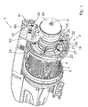
- Fig. 1 shows a perspective view of a weft feeder device 1 with a thread braking device 3.
- Fig. 2 shows a detail of Fig. 1 .
- the weft feeder device 1 comprises a winding drum 5 on which a rotating winding arm 6 winds a plurality of turns or windings of a weft thread 7.
- the rotating winding arm 6 rotates about a drum axis 9.
- a thread guide 11 is arranged in front of the thread braking device 3 .
- a rounded front end of the winding drum 5 that extends uninterrupted or continuous over the circumference of the front end of the winding drum 5, is referred to as withdrawal rim 13.
- the thread braking device 3 shown in Fig. 2 comprises a circumferential braking band 15, a support structure 17 having an annular shape, a holder 19, a pressing ring 21, a spring assembly 22 with a plurality of spring elements 23, and an actuator 25.
- the support structure 17 comprises a cage 31 and a retaining element 33 that is mounted on an outer support ring 18 of the cage 31.
- the retaining element 33 retains the braking band 15.
- the retaining element 33 is shaped as a retaining ring, and the circumferential braking band 15 is shaped as an uninterrupted or continuous circumferential braking band.
- the weft thread 7 is withdrawn via the thread guide 11 from the winding drum 5, wherein during withdrawal the weft thread 7 withdrawn is moving about the withdrawal rim 13 in a braking zone 16 between the withdrawal rim 13 and the braking band 15.
- a braking surface 14 of the braking band 15 contacts the withdrawal rim 13 in order to form a braking zone 16 for the weft thread 7 withdrawn from the weft feeder device 1.
- the braking band 15 is made of wear resistant material, e.g. of a metal or a metal alloy, in particular stainless steel, and has the shape of a frusto-conical element.
- the braking band 15 is resiliently deformable in a radial direction of the drum axis 9, but preferably has a high stiffness in the axial direction. As will be explained in more detail below, a radial stiffness in the braking zone 16 depends on the axial position of the support structure 17 with respect to the withdrawal rim 13.
- an axial position of the support structure 17 in the direction of the drum axis 9 is determined by means of the actuator 25 acting on the support structure 17.
- the support structure 17 comprising the cage 31 and the retaining ring 33 has an essentially frusto-conical shape, wherein the larger end 45 faces towards the winding drum 5.
- the pressing ring 21 is provided at the smaller end 47 of the support structure 17, more particular at the smaller end of the cage 31.
- the actuator 25 is provided with a moveable shaft 27 coupled to pressing ring 21.
- the moveable shaft 27 is arranged coaxial to the thread guide 11 and has a central core for a passage of the weft thread 7.
- the actuator 25 can be driven to move the pressing ring 21 towards the winding drum 5, whereby an axial force is exerted on the support structure 17, or away from the winding drum 5 for decreasing a force exerted or for even moving the braking band 15 away from the withdrawal rim 13.
- the support structure 17 in the embodiment shown is further held in the holder 19 by means of the spring assembly 22 having several spring elements 23.
- the holder 19 is mounted to a frame 49 of the weft feeder device 1.
- the spring elements 23 also exert an axial force on the support structure 17.
- the spring elements 23 allow to center the support structure 17.
- an axial mounting position of the holder 19 at the frame 49 can also be adjusted in the direction of the drum axis 9.
- the holder 19 is moveable in the direction of the drum axis 9 by means of a setting unit 60, which setting unit 60 comprises a setting screw 61 to set the axial mounting position of the holder 19.
- the axial mounting position of the holder 19 determines the axial force exerted by the spring elements 23 on the support structure 17.
- the holder 19 is omitted.
- a cardan suspension 50, 52 is arranged between the pressing ring 21 and the cage 31 of the support structure 17.
- the thread braking device 3 shown in Figs. 1 and 2 further comprises an interface 63 for selecting a force exerted by the actuator 25.
- the interface 63 is designed easy to use.
- N preselected positions and/or N preselected profiles of positions and/or N preselected force values and/or N preselected profiles of force values are stored in the thread braking device in an ascending to descending order and the operator selects a number between 0 and N for having a higher or lower radial stiffness without having to know the position or force associated with the selected number.
- a profile of positions and/or a profile of force values for example can be determined in function of the angular position of the main axis of the weaving machine.
- the interface 63 comprises a turnable knob 62 for selecting the radial stiffness between a level 0 and a level N, with 0 being the lowest level of radial stiffness and N being the highest level of radial stiffness.
- the interface 63 further comprises a display 64 to show the selected level.
- the actuator 25 has a flexibly suspended rotor 26 in order to eliminate parasitic and non-predictable forces due to friction.
- the rotor 26 is suspended by two spring devices 28 allowing the rotor 26 to move in axial direction, but not in a direction perpendicular to the axial direction.
- the rotor 26 is made in one piece with the moveable shaft 27 of the actuator 25.
- a housing 29 is provided, so that the actuator 25 is sealed dust-free.
- the spring devices 28 allow that the cage 31 together with the rotor 26 can move freely in the axial direction, and can be retained in position in a direction perpendicular to the axial direction. By the spring devices 28, the rotor 26 can also move in the axial direction without friction.
- the spring device 28 for example comprises an outer profile 30 to be attached to the housing 29 and an inner profile 32 that suspends the shaft 27, wherein the outer profile 30 is connected to the inner profile 32 by several blade springs 36 in order to allow an axial movement of the shaft 27, but to prevent a movement perpendicular to the axial direction.
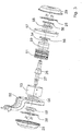
- Fig. 3 shows the actuator 25 in an explosive view.
- the actuator 25 comprises a coil 51, a ring 53, a main support 55, a support 57, a permanent magnet 59, a screw-nut 54, positioning parts 56, fixation parts 58 and several elements for assembling the actuator 25.
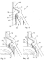
- the thread braking device 3 without the actuator 25 is shown in detail in Figs. 5 to 8 .
- the support structure 17 has an essentially frusto-conical shape and extends beyond the braking band 15, wherein a larger end 45 of the support structure 17 is designed as an annular weft thread guiding element controlling an entrance of the weft thread 7 into the braking zone 16 and influencing or limiting the formation of a weft thread balloon.
- the support structure 17 comprises the cage 31 and the retaining element 33 that is mounted on an outer support ring 18 of the cage 31. The retaining element 33 is arranged at the larger end 45 of the support structure 17.
- the spring elements 23 are connected to the smaller end 47 of the support structure 17, more particular to the smaller end of the cage 31.
- the cage 31 has an essentially frusto-conical shape and comprises a plurality of arms 34 separated from one another in the circumferential direction by interspaces.
- Fig. 8 shows partially in a sectional view a detail of the thread braking device of Figs. 5 to 7 .
- the braking band 15 is mounted to the retaining element 33 of the support structure 17.
- the retaining element 33 is mounted to the cage 31.
- the retaining element 33 is inserted in the cage 31.
- the retaining element 33 is glued to the outer support ring 18 of the cage 31.
- the retaining element 33 is floatingly supported by the cage 31.
- the cage 31 and the retaining element 33 are made of different material, but formed integrally for example using two-component injection molding.
- the retaining element 33 is made of an elastically deformable material, such as polyurethane.
- the cage 31 is made of a material and designed to have a high axial stiffness. When exerting an axial force to the support structure 17 while the braking band 15 contacts the withdrawal rim 13 (see Fig. 1 ), the retaining element 33 is deformed.
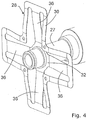
- the retaining element 33 shaped as a retaining ring has a double-curved cross-section for forming two annular portions 35, 37 of different diameter, which are coaxially arranged and, hence, arranged at a distance of one another in the radial direction.
- the portion 35 having the larger diameter abuts against the cage 31.
- the braking band 15 is held by the portion 37 having the smaller diameter.
- the portion 37 of the retaining element 33 having a smaller diameter is provided for receiving the braking band 15, wherein a rear side of the braking band 15 contacts the portion 37 of the retaining element 33 having a smaller diameter.
- the braking band 15 can be glued to the retaining element 33.
- a stiffening element 41 surrounding the braking band 15 at a rear side of the braking band 15 opposite to the braking surface 14 of the braking band 15 is provided.
- the stiffening element 41 is formed by a contour of the cage 31 and forms a circumferential stiffening element 41.
- the braking band 15 is arranged at a distance of the stiffening element 41.
- the retaining element 33 of the support structure 17 is deformed so that the braking band 15 at its rear side via the annual portion 37 of the retaining element 33 is supported by the stiffening element 41. Thereby, a radial stiffness in the braking zone 16 is increased.
- the portion 37 of the retaining element 33 having a smaller diameter is arranged between the braking band 15 and the stiffening element 41 when the braking band 15 is supported by the stiffening element 41 and contacts the stiffening element 41.
- the retaining element 33 can have a collar 24 to guide a weft thread to the braking zone 16.
- Fig. 9 shows a detail of the thread braking device 3 in a somewhat deformed state, wherein the radial stiffness in the braking zone 16 is solely determined by the radial stiffness of the braking band 15.
- Fig. 10 shows a detail of the thread braking device 3 in a more deformed state, wherein the braking band 15 is supported by the stiffening element 41 and the radial stiffness is primarily defined by the stiffening element 41.
- both the radial stiffness, also named contact stiffness, and the axial stiffness, also named macroscopic stiffness, are increased, in particular the stiffness of the braking band 15 is increased at the height of the location where the weft thread 7 is braked by the braking band 15.
- the axial stiffness of the thread braking device 3 is non-linear.
- Fig. 11 schematically shows a curve of a force F exerted in the braking zone 16 as a function of the axial position X of the pressing ring 21.
- a low force F is exerted, wherein a necessary displacement ⁇ x of the pressing ring 21 for increasing the force ⁇ F is rather high.
- the retaining element 33 is deformed so that the braking band 15 is supported by the stiffening element 41, wherein in the embodiment shown, the braking band 15 contacts the stiffening element 41 via the portion 37 of the retaining element 33.
- a necessary displacement ⁇ x of the pressing ring 21 for further increasing the force ⁇ F is comparatively low.
- Fig. 12 shows a detail of an alternative embodiment of a support structure 17 with a cage 31 and a retaining element 33, wherein two stiffening elements 41, 43 are formed at a contour of the cage 31.
- the braking band 15 is fixed to the annual portion 37 of the retaining element 33.
- the retaining element 33 for the braking band 15 will first be supported by the first stiffening element 41, in particular the retaining element 33 retaining the braking band 15 will first contact the first stiffening element 41.
- the retaining element 33 for the braking band 15 Upon a further deformation, the retaining element 33 for the braking band 15 will additionally be supported by the second stiffening element 43, in particular the retaining element 33 will contact the second stiffening element 43. It will be understood by the person skilled in the art that the number, the position and the shape of the stiffening elements 41, 43 is only by way of example and various modifications are possible. In the embodiment shown, the retaining element 33 is not provided with a collar 24 (see Fig. 8 ).
- a retaining element 33 can be provided with a hook shaped retaining slot for receiving the braking band 15, wherein the braking band 15 similar as known from EP 0 963 335 B1 is floatingly retained in the retaining slot.
- the hook shaped retaining slot can also be shaped similar as the collar 24 shown in Fig. 4 .
- the braking band 15 is made in one piece with the retaining element 33, and hence the braking band 15 is mounted directly to the outer support ring 18 of the cage 31.
- the braking band 15 that is supported by the support structure 17 can make direct contact with stiffening elements 41, 43 when the braking band 15 is deformed, in other words the braking band 15 can abut directly against stiffening elements 41, 43.
Landscapes
- Engineering & Computer Science (AREA)
- Textile Engineering (AREA)
- Looms (AREA)
Claims (15)
- Dispositif de freinage de fil pour un dispositif délivreur de trame (1) prévu d'un rebord de retrait (13), le dispositif de freinage de fil (3) comprenant une bande de freinage annulaire (15) avec une forme tronconique et une surface de freinage (14) adaptée pour entrer en contact avec le rebord de retrait (13) du dispositif délivreur de trame (1) pour former une zone de freinage (16) pour un fil de trame (7) retiré du dispositif délivreur de trame (1), et une structure de support (17), dans lequel la bande de freinage annulaire (15) est supportée par la structure de support (17), et dans laquelle la structure de support (17) est au moins partiellement élastiquement déformable par une force axiale exercée sur la structure de support (17), dans laquelle la structure de support (17) est prévue d'au moins un élément raidisseur (41, 43) entourant la bande de freinage annulaire (15) à un côté arrière de la bande de freinage annulaire (15) opposé à la surface de freinage (14), et dans laquelle la structure de support (17) comprend un élément de retenue retenant la bande de freinage annulaire (15), caractérisé en ce que l'élément de retenue (33) consiste en une bague de retenue constituée d'un matériau élastiquement déformable, dans lequel en exerçant une force sur la structure de support (17), l'élément de retenue (33) est déformé, provoquant ainsi un déplacement de la bande de freinage annulaire (15) vers l'élément raidisseur (41, 43) jusqu'à ce que la bande de freinage annulaire (15) est supportée par l'élément raidisseur (41, 43), dans lequel à l'état non déformé de l'élément de retenue (33) de la structure de support (17) la bande de freinage annulaire (15) est disposée à une distance de l'élément raidisseur (41, 43) et en exerçant une force axiale sur la structure de support (17), l'élément de retenue (33) de la structure de support (17) est déformable de sorte que la bande de freinage annulaire (15) au côté arrière de la bande de freinage annulaire (15) est supportée par l'élément raidisseur (41, 43).
- Dispositif de freinage de fil selon la revendication 1, caractérisé en ce que l'au moins un élément raidisseur (41, 43) a un contour périphérique continu.
- Dispositif de freinage de fil selon la revendication 1 ou 2, caractérisé en ce que la structure de support (17) comprend une cage (31) avec une forme tronconique, dans laquelle la bande de freinage annulaire (15) est disposée à l'intérieur de la cage (31).
- Dispositif de freinage de fil selon la revendication 3, caractérisé en ce que l'au moins un élément raidisseur (41, 43) est formé par un contour de la cage (31).
- Dispositif de freinage de fil selon la revendication 3 ou 4, caractérisé en ce qu'une bague de pression (21) est prévue à une extrémité plus petite de la cage (31) pour exercer une force axiale sur la structure de support (17).
- Dispositif de freinage de fil selon l'une quelconque des revendications 1 à 5, caractérisé en ce qu'un actionneur (25) est prévu pour exercer une force axiale sur la structure de support (17).
- Dispositif de freinage de fil selon la revendication 6, caractérisé en ce que l'actionneur (25) est commandé par force ou commandé par position.
- Dispositif de freinage de fil selon la revendication 7, caractérisé en ce que l'actionneur (25) est commandé par retour de force ou commandé par retour de position.
- Dispositif de freinage de fil selon l'une quelconque des revendications 6 à 8, caractérisé en ce que l'actionneur (25) est un actionneur à bobine magnétique.
- Dispositif de freinage de fil selon l'une quelconque des revendications 6 à 9, caractérisé en ce que l'actionneur (25) comprend un rotor (26) suspendu par des dispositifs à ressort (28), qui permettent que le rotor (26) se déplace dans une direction axiale, mais pas dans une direction perpendiculaire à la direction axiale.
- Dispositif de freinage de fil selon l'une quelconque des revendications 6 à 10, caractérisé en ce qu'une interface (63) est prévue pour sélectionner des valeurs de force et/ou des profils de valeurs de force exercés par l'actionneur (25).
- Dispositif de freinage de fil selon l'une quelconque des revendications 6 à 11, caractérisé en ce que l'actionneur (25) peut fonctionner pour éloigner la bande de freinage (15) du rebord de retrait (13).
- Dispositif de freinage de fil selon l'une quelconque des revendications 1 à 12, caractérisé en ce qu'un appui (19) est prévu, dans lequel la structure de support (17) est déplaçable dans la direction axiale maintenue par l'appui (19).
- Dispositif de freinage de fil selon la revendication 13, caractérisé en ce que la structure de support (17) est maintenue par l'appui (19) en utilisant un ensemble ressort (22).
- Dispositif délivreur de trame comprenant un tambour d'enroulement (5) avec un rebord de retrait (13), caractérisé en ce qu'un dispositif de freinage de fil (3) selon l'une quelconque des revendications 1 à 14 est disposé devant le rebord de retrait (13), le dispositif de freinage de fil (3) comprenant une bande de freinage annulaire (15) avec une forme tronconique et une surface de freinage (14) adaptée pour entrer en contact avec le rebord de retrait (13).
Applications Claiming Priority (2)
| Application Number | Priority Date | Filing Date | Title |
|---|---|---|---|
| BE2017/0123A BE1025536B1 (nl) | 2017-09-07 | 2017-09-07 | Draadreminrichting voor een inslagtoevoerinrichting |
| PCT/EP2018/071227 WO2019048158A1 (fr) | 2017-09-07 | 2018-08-06 | Dispositif de freinage de fil pour un dispositif d'alimentation de trame |
Publications (2)
| Publication Number | Publication Date |
|---|---|
| EP3679186A1 EP3679186A1 (fr) | 2020-07-15 |
| EP3679186B1 true EP3679186B1 (fr) | 2022-01-05 |
Family
ID=60117405
Family Applications (1)
| Application Number | Title | Priority Date | Filing Date |
|---|---|---|---|
| EP18746720.4A Active EP3679186B1 (fr) | 2017-09-07 | 2018-08-06 | Dispositif de freinage de fil pour un dispositif d'alimentation de trame |
Country Status (4)
| Country | Link |
|---|---|
| EP (1) | EP3679186B1 (fr) |
| CN (1) | CN111051586B (fr) |
| BE (1) | BE1025536B1 (fr) |
| WO (1) | WO2019048158A1 (fr) |
Citations (1)
| Publication number | Priority date | Publication date | Assignee | Title |
|---|---|---|---|---|
| EP0963335B1 (fr) * | 1997-02-24 | 2001-10-24 | Iro Ab | Appareil d'alimentation en fil et tendeur |
Family Cites Families (11)
| Publication number | Priority date | Publication date | Assignee | Title |
|---|---|---|---|---|
| IT1133900B (it) * | 1980-10-15 | 1986-07-24 | Roy Electrotex Spa | Mezzi per effettuare la frenatura del filato in uscita in dispositivi alimentatori di filato a tensione costante e regolabile,particolarmente per macchine tessili |
| ES2110458T3 (es) | 1991-09-20 | 1998-02-16 | Lgl Electronics Spa | Dispositivo autoajustable para frenar el hilo en las unidades alimentadoras de trama. |
| IT1268111B1 (it) * | 1994-10-10 | 1997-02-20 | Lgl Electronics Spa | Dispositivo di frenatura modulata positiva del filato, per apparecchi alimentatori di trama |
| IT1289696B1 (it) * | 1996-11-29 | 1998-10-16 | Lgl Electronics Spa | Perfezionamento ai dispositivi di frenatura autoregolante del filato, per apparecchi alimentatori di trama |
| WO2007048528A1 (fr) * | 2005-10-27 | 2007-05-03 | Memminger-Iro Gmbh | Dispositif de controle entierement automatique de longueur de fil |
| EP2058423A1 (fr) * | 2007-10-10 | 2009-05-13 | Iro Ab | Machine à tisser, passe-fil et procédé d'insertion d'un passe-fil |
| CN102477653A (zh) * | 2010-11-24 | 2012-05-30 | 大连创达技术交易市场有限公司 | 一种新型纱线制动装置 |
| ITMI20112267A1 (it) * | 2011-12-15 | 2013-06-16 | Btsr Int Spa | Dispositivo di alimentazione di filo ad una macchina tessile |
| EP2924156B1 (fr) * | 2014-03-28 | 2016-11-23 | L.G.L. Electronics S.p.A. | Dispositif de freinage de fil pour dispositifs d'alimentation en fil de stockage |
| CN106574411B (zh) * | 2014-05-09 | 2019-04-23 | 必佳乐公司 | 输纬器装置 |
| EP2993260B1 (fr) * | 2014-09-05 | 2017-04-19 | L.G.L. Electronics S.p.A. | Dispositif d'alimentation de fil avec tambour rotatif de stockage et capteur de déroulement du fil |
-
2017
- 2017-09-07 BE BE2017/0123A patent/BE1025536B1/nl not_active IP Right Cessation
-
2018
- 2018-08-06 CN CN201880058115.2A patent/CN111051586B/zh active Active
- 2018-08-06 EP EP18746720.4A patent/EP3679186B1/fr active Active
- 2018-08-06 WO PCT/EP2018/071227 patent/WO2019048158A1/fr not_active Ceased
Patent Citations (1)
| Publication number | Priority date | Publication date | Assignee | Title |
|---|---|---|---|---|
| EP0963335B1 (fr) * | 1997-02-24 | 2001-10-24 | Iro Ab | Appareil d'alimentation en fil et tendeur |
Also Published As
| Publication number | Publication date |
|---|---|
| BE1025536A1 (nl) | 2019-04-02 |
| WO2019048158A9 (fr) | 2021-09-23 |
| BE1025536B1 (nl) | 2019-04-08 |
| EP3679186A1 (fr) | 2020-07-15 |
| WO2019048158A1 (fr) | 2019-03-14 |
| CN111051586A (zh) | 2020-04-21 |
| CN111051586B (zh) | 2021-05-11 |
Similar Documents
| Publication | Publication Date | Title |
|---|---|---|
| EP0049897B1 (fr) | Frein de fil pour magasin de fil | |
| KR100245609B1 (ko) | 씨실 공급장치를 위한 자동조절 실 제동장치 | |
| EP0855358A1 (fr) | Fournisseur de fil | |
| JP6967881B2 (ja) | 糸クランプ装置 | |
| CN103946138A (zh) | 具有磁制动器的储存类型的纱线供给器 | |
| EP2924156B1 (fr) | Dispositif de freinage de fil pour dispositifs d'alimentation en fil de stockage | |
| EP3679186B1 (fr) | Dispositif de freinage de fil pour un dispositif d'alimentation de trame | |
| TWI296660B (en) | Yarn braking device | |
| US3850394A (en) | Bobbin holder | |
| JP2007523301A (ja) | 高速回転するロータを支承するための軸受装置 | |
| CN1094108C (zh) | 带纱线制动装置的喂纱器 | |
| JP5684060B2 (ja) | 軸方向の調整が可能な磁気ベアリングとこのベアリングの取り付け方法 | |
| US4466576A (en) | Metering drum for filamentary material | |
| EP0730054A1 (fr) | Anneau de filage | |
| CN110656433B (zh) | 喂纱设备和用于运行喂纱设备的方法 | |
| EP3608460B1 (fr) | Dispositif de freinage de trame pour fournisseurs de fil d'accumulateur | |
| KR20010072599A (ko) | 직기의 얀 공급기용 얀 브레이크 | |
| US3323299A (en) | Device for controlling the position of control elements in stationarily held bobbin carriers, especially in two-forone twisting spindles | |
| CN1189372C (zh) | 盘式制动器 | |
| TW202035268A (zh) | 紗線夾持之裝置及用於其之裝載與卸載裝置 | |
| KR20000035928A (ko) | 방적사 제동 장치 및 방적사 공급 장치 | |
| EP0699790A1 (fr) | Organe de retenue de fil pour fournisseur de trame de métier à jet d'air | |
| CN110656434B (zh) | 喂纱器和带有喂纱器的系统 | |
| US4305246A (en) | Ring rail with air-suspended spinning or twisting rings | |
| JP3341081B2 (ja) | 糸フィーダ |
Legal Events
| Date | Code | Title | Description |
|---|---|---|---|
| STAA | Information on the status of an ep patent application or granted ep patent |
Free format text: STATUS: UNKNOWN |
|
| STAA | Information on the status of an ep patent application or granted ep patent |
Free format text: STATUS: THE INTERNATIONAL PUBLICATION HAS BEEN MADE |
|
| PUAI | Public reference made under article 153(3) epc to a published international application that has entered the european phase |
Free format text: ORIGINAL CODE: 0009012 |
|
| STAA | Information on the status of an ep patent application or granted ep patent |
Free format text: STATUS: REQUEST FOR EXAMINATION WAS MADE |
|
| 17P | Request for examination filed |
Effective date: 20200116 |
|
| AK | Designated contracting states |
Kind code of ref document: A1 Designated state(s): AL AT BE BG CH CY CZ DE DK EE ES FI FR GB GR HR HU IE IS IT LI LT LU LV MC MK MT NL NO PL PT RO RS SE SI SK SM TR |
|
| AX | Request for extension of the european patent |
Extension state: BA ME |
|
| DAV | Request for validation of the european patent (deleted) | ||
| DAX | Request for extension of the european patent (deleted) | ||
| STAA | Information on the status of an ep patent application or granted ep patent |
Free format text: STATUS: EXAMINATION IS IN PROGRESS |
|
| 17Q | First examination report despatched |
Effective date: 20210217 |
|
| GRAP | Despatch of communication of intention to grant a patent |
Free format text: ORIGINAL CODE: EPIDOSNIGR1 |
|
| STAA | Information on the status of an ep patent application or granted ep patent |
Free format text: STATUS: GRANT OF PATENT IS INTENDED |
|
| INTG | Intention to grant announced |
Effective date: 20210824 |
|
| GRAJ | Information related to disapproval of communication of intention to grant by the applicant or resumption of examination proceedings by the epo deleted |
Free format text: ORIGINAL CODE: EPIDOSDIGR1 |
|
| STAA | Information on the status of an ep patent application or granted ep patent |
Free format text: STATUS: EXAMINATION IS IN PROGRESS |
|
| GRAP | Despatch of communication of intention to grant a patent |
Free format text: ORIGINAL CODE: EPIDOSNIGR1 |
|
| STAA | Information on the status of an ep patent application or granted ep patent |
Free format text: STATUS: GRANT OF PATENT IS INTENDED |
|
| INTC | Intention to grant announced (deleted) | ||
| INTG | Intention to grant announced |
Effective date: 20211021 |
|
| GRAS | Grant fee paid |
Free format text: ORIGINAL CODE: EPIDOSNIGR3 |
|
| GRAA | (expected) grant |
Free format text: ORIGINAL CODE: 0009210 |
|
| STAA | Information on the status of an ep patent application or granted ep patent |
Free format text: STATUS: THE PATENT HAS BEEN GRANTED |
|
| AK | Designated contracting states |
Kind code of ref document: B1 Designated state(s): AL AT BE BG CH CY CZ DE DK EE ES FI FR GB GR HR HU IE IS IT LI LT LU LV MC MK MT NL NO PL PT RO RS SE SI SK SM TR |
|
| REG | Reference to a national code |
Ref country code: GB Ref legal event code: FG4D |
|
| REG | Reference to a national code |
Ref country code: CH Ref legal event code: EP |
|
| REG | Reference to a national code |
Ref country code: AT Ref legal event code: REF Ref document number: 1460684 Country of ref document: AT Kind code of ref document: T Effective date: 20220115 |
|
| REG | Reference to a national code |
Ref country code: DE Ref legal event code: R096 Ref document number: 602018029137 Country of ref document: DE |
|
| REG | Reference to a national code |
Ref country code: IE Ref legal event code: FG4D |
|
| REG | Reference to a national code |
Ref country code: LT Ref legal event code: MG9D |
|
| REG | Reference to a national code |
Ref country code: NL Ref legal event code: MP Effective date: 20220105 |
|
| REG | Reference to a national code |
Ref country code: AT Ref legal event code: MK05 Ref document number: 1460684 Country of ref document: AT Kind code of ref document: T Effective date: 20220105 |
|
| PG25 | Lapsed in a contracting state [announced via postgrant information from national office to epo] |
Ref country code: NL Free format text: LAPSE BECAUSE OF FAILURE TO SUBMIT A TRANSLATION OF THE DESCRIPTION OR TO PAY THE FEE WITHIN THE PRESCRIBED TIME-LIMIT Effective date: 20220105 |
|
| PG25 | Lapsed in a contracting state [announced via postgrant information from national office to epo] |
Ref country code: SE Free format text: LAPSE BECAUSE OF FAILURE TO SUBMIT A TRANSLATION OF THE DESCRIPTION OR TO PAY THE FEE WITHIN THE PRESCRIBED TIME-LIMIT Effective date: 20220105 Ref country code: RS Free format text: LAPSE BECAUSE OF FAILURE TO SUBMIT A TRANSLATION OF THE DESCRIPTION OR TO PAY THE FEE WITHIN THE PRESCRIBED TIME-LIMIT Effective date: 20220105 Ref country code: PT Free format text: LAPSE BECAUSE OF FAILURE TO SUBMIT A TRANSLATION OF THE DESCRIPTION OR TO PAY THE FEE WITHIN THE PRESCRIBED TIME-LIMIT Effective date: 20220505 Ref country code: NO Free format text: LAPSE BECAUSE OF FAILURE TO SUBMIT A TRANSLATION OF THE DESCRIPTION OR TO PAY THE FEE WITHIN THE PRESCRIBED TIME-LIMIT Effective date: 20220405 Ref country code: LT Free format text: LAPSE BECAUSE OF FAILURE TO SUBMIT A TRANSLATION OF THE DESCRIPTION OR TO PAY THE FEE WITHIN THE PRESCRIBED TIME-LIMIT Effective date: 20220105 Ref country code: HR Free format text: LAPSE BECAUSE OF FAILURE TO SUBMIT A TRANSLATION OF THE DESCRIPTION OR TO PAY THE FEE WITHIN THE PRESCRIBED TIME-LIMIT Effective date: 20220105 Ref country code: ES Free format text: LAPSE BECAUSE OF FAILURE TO SUBMIT A TRANSLATION OF THE DESCRIPTION OR TO PAY THE FEE WITHIN THE PRESCRIBED TIME-LIMIT Effective date: 20220105 Ref country code: BG Free format text: LAPSE BECAUSE OF FAILURE TO SUBMIT A TRANSLATION OF THE DESCRIPTION OR TO PAY THE FEE WITHIN THE PRESCRIBED TIME-LIMIT Effective date: 20220405 |
|
| PG25 | Lapsed in a contracting state [announced via postgrant information from national office to epo] |
Ref country code: PL Free format text: LAPSE BECAUSE OF FAILURE TO SUBMIT A TRANSLATION OF THE DESCRIPTION OR TO PAY THE FEE WITHIN THE PRESCRIBED TIME-LIMIT Effective date: 20220105 Ref country code: LV Free format text: LAPSE BECAUSE OF FAILURE TO SUBMIT A TRANSLATION OF THE DESCRIPTION OR TO PAY THE FEE WITHIN THE PRESCRIBED TIME-LIMIT Effective date: 20220105 Ref country code: GR Free format text: LAPSE BECAUSE OF FAILURE TO SUBMIT A TRANSLATION OF THE DESCRIPTION OR TO PAY THE FEE WITHIN THE PRESCRIBED TIME-LIMIT Effective date: 20220406 Ref country code: FI Free format text: LAPSE BECAUSE OF FAILURE TO SUBMIT A TRANSLATION OF THE DESCRIPTION OR TO PAY THE FEE WITHIN THE PRESCRIBED TIME-LIMIT Effective date: 20220105 Ref country code: AT Free format text: LAPSE BECAUSE OF FAILURE TO SUBMIT A TRANSLATION OF THE DESCRIPTION OR TO PAY THE FEE WITHIN THE PRESCRIBED TIME-LIMIT Effective date: 20220105 |
|
| PG25 | Lapsed in a contracting state [announced via postgrant information from national office to epo] |
Ref country code: IS Free format text: LAPSE BECAUSE OF FAILURE TO SUBMIT A TRANSLATION OF THE DESCRIPTION OR TO PAY THE FEE WITHIN THE PRESCRIBED TIME-LIMIT Effective date: 20220505 |
|
| REG | Reference to a national code |
Ref country code: DE Ref legal event code: R097 Ref document number: 602018029137 Country of ref document: DE |
|
| PG25 | Lapsed in a contracting state [announced via postgrant information from national office to epo] |
Ref country code: SM Free format text: LAPSE BECAUSE OF FAILURE TO SUBMIT A TRANSLATION OF THE DESCRIPTION OR TO PAY THE FEE WITHIN THE PRESCRIBED TIME-LIMIT Effective date: 20220105 Ref country code: SK Free format text: LAPSE BECAUSE OF FAILURE TO SUBMIT A TRANSLATION OF THE DESCRIPTION OR TO PAY THE FEE WITHIN THE PRESCRIBED TIME-LIMIT Effective date: 20220105 Ref country code: RO Free format text: LAPSE BECAUSE OF FAILURE TO SUBMIT A TRANSLATION OF THE DESCRIPTION OR TO PAY THE FEE WITHIN THE PRESCRIBED TIME-LIMIT Effective date: 20220105 Ref country code: EE Free format text: LAPSE BECAUSE OF FAILURE TO SUBMIT A TRANSLATION OF THE DESCRIPTION OR TO PAY THE FEE WITHIN THE PRESCRIBED TIME-LIMIT Effective date: 20220105 Ref country code: DK Free format text: LAPSE BECAUSE OF FAILURE TO SUBMIT A TRANSLATION OF THE DESCRIPTION OR TO PAY THE FEE WITHIN THE PRESCRIBED TIME-LIMIT Effective date: 20220105 Ref country code: CZ Free format text: LAPSE BECAUSE OF FAILURE TO SUBMIT A TRANSLATION OF THE DESCRIPTION OR TO PAY THE FEE WITHIN THE PRESCRIBED TIME-LIMIT Effective date: 20220105 |
|
| PLBE | No opposition filed within time limit |
Free format text: ORIGINAL CODE: 0009261 |
|
| STAA | Information on the status of an ep patent application or granted ep patent |
Free format text: STATUS: NO OPPOSITION FILED WITHIN TIME LIMIT |
|
| PG25 | Lapsed in a contracting state [announced via postgrant information from national office to epo] |
Ref country code: AL Free format text: LAPSE BECAUSE OF FAILURE TO SUBMIT A TRANSLATION OF THE DESCRIPTION OR TO PAY THE FEE WITHIN THE PRESCRIBED TIME-LIMIT Effective date: 20220105 |
|
| 26N | No opposition filed |
Effective date: 20221006 |
|
| PG25 | Lapsed in a contracting state [announced via postgrant information from national office to epo] |
Ref country code: SI Free format text: LAPSE BECAUSE OF FAILURE TO SUBMIT A TRANSLATION OF THE DESCRIPTION OR TO PAY THE FEE WITHIN THE PRESCRIBED TIME-LIMIT Effective date: 20220105 |
|
| PG25 | Lapsed in a contracting state [announced via postgrant information from national office to epo] |
Ref country code: MC Free format text: LAPSE BECAUSE OF FAILURE TO SUBMIT A TRANSLATION OF THE DESCRIPTION OR TO PAY THE FEE WITHIN THE PRESCRIBED TIME-LIMIT Effective date: 20220105 |
|
| REG | Reference to a national code |
Ref country code: CH Ref legal event code: PL |
|
| GBPC | Gb: european patent ceased through non-payment of renewal fee |
Effective date: 20220806 |
|
| PG25 | Lapsed in a contracting state [announced via postgrant information from national office to epo] |
Ref country code: LU Free format text: LAPSE BECAUSE OF NON-PAYMENT OF DUE FEES Effective date: 20220806 Ref country code: LI Free format text: LAPSE BECAUSE OF NON-PAYMENT OF DUE FEES Effective date: 20220831 Ref country code: CH Free format text: LAPSE BECAUSE OF NON-PAYMENT OF DUE FEES Effective date: 20220831 |
|
| P01 | Opt-out of the competence of the unified patent court (upc) registered |
Effective date: 20230519 |
|
| PG25 | Lapsed in a contracting state [announced via postgrant information from national office to epo] |
Ref country code: IE Free format text: LAPSE BECAUSE OF NON-PAYMENT OF DUE FEES Effective date: 20220806 Ref country code: FR Free format text: LAPSE BECAUSE OF NON-PAYMENT OF DUE FEES Effective date: 20220831 |
|
| PG25 | Lapsed in a contracting state [announced via postgrant information from national office to epo] |
Ref country code: GB Free format text: LAPSE BECAUSE OF NON-PAYMENT OF DUE FEES Effective date: 20220806 |
|
| PGFP | Annual fee paid to national office [announced via postgrant information from national office to epo] |
Ref country code: TR Payment date: 20230731 Year of fee payment: 6 Ref country code: IT Payment date: 20230831 Year of fee payment: 6 |
|
| PGFP | Annual fee paid to national office [announced via postgrant information from national office to epo] |
Ref country code: DE Payment date: 20230824 Year of fee payment: 6 Ref country code: BE Payment date: 20230710 Year of fee payment: 6 |
|
| PG25 | Lapsed in a contracting state [announced via postgrant information from national office to epo] |
Ref country code: CY Free format text: LAPSE BECAUSE OF FAILURE TO SUBMIT A TRANSLATION OF THE DESCRIPTION OR TO PAY THE FEE WITHIN THE PRESCRIBED TIME-LIMIT Effective date: 20220105 |
|
| PG25 | Lapsed in a contracting state [announced via postgrant information from national office to epo] |
Ref country code: MK Free format text: LAPSE BECAUSE OF FAILURE TO SUBMIT A TRANSLATION OF THE DESCRIPTION OR TO PAY THE FEE WITHIN THE PRESCRIBED TIME-LIMIT Effective date: 20220105 Ref country code: HU Free format text: LAPSE BECAUSE OF FAILURE TO SUBMIT A TRANSLATION OF THE DESCRIPTION OR TO PAY THE FEE WITHIN THE PRESCRIBED TIME-LIMIT; INVALID AB INITIO Effective date: 20180806 |
|
| PG25 | Lapsed in a contracting state [announced via postgrant information from national office to epo] |
Ref country code: MT Free format text: LAPSE BECAUSE OF FAILURE TO SUBMIT A TRANSLATION OF THE DESCRIPTION OR TO PAY THE FEE WITHIN THE PRESCRIBED TIME-LIMIT Effective date: 20220105 |
|
| REG | Reference to a national code |
Ref country code: DE Ref legal event code: R119 Ref document number: 602018029137 Country of ref document: DE |
|
| REG | Reference to a national code |
Ref country code: BE Ref legal event code: MM Effective date: 20240831 |
|
| PG25 | Lapsed in a contracting state [announced via postgrant information from national office to epo] |
Ref country code: DE Free format text: LAPSE BECAUSE OF NON-PAYMENT OF DUE FEES Effective date: 20250301 |
|
| PG25 | Lapsed in a contracting state [announced via postgrant information from national office to epo] |
Ref country code: BE Free format text: LAPSE BECAUSE OF NON-PAYMENT OF DUE FEES Effective date: 20240831 Ref country code: IT Free format text: LAPSE BECAUSE OF NON-PAYMENT OF DUE FEES Effective date: 20240806 |