EP3679231B1 - Verbrennungsmotoranordnung - Google Patents
Verbrennungsmotoranordnung Download PDFInfo
- Publication number
- EP3679231B1 EP3679231B1 EP17761501.0A EP17761501A EP3679231B1 EP 3679231 B1 EP3679231 B1 EP 3679231B1 EP 17761501 A EP17761501 A EP 17761501A EP 3679231 B1 EP3679231 B1 EP 3679231B1
- Authority
- EP
- European Patent Office
- Prior art keywords
- cylinder
- internal combustion
- combustion engine
- vehicle
- engine arrangement
- Prior art date
- Legal status (The legal status is an assumption and is not a legal conclusion. Google has not performed a legal analysis and makes no representation as to the accuracy of the status listed.)
- Active
Links
Images


Classifications
-
- F—MECHANICAL ENGINEERING; LIGHTING; HEATING; WEAPONS; BLASTING
- F02—COMBUSTION ENGINES; HOT-GAS OR COMBUSTION-PRODUCT ENGINE PLANTS
- F02B—INTERNAL-COMBUSTION PISTON ENGINES; COMBUSTION ENGINES IN GENERAL
- F02B41/00—Engines characterised by special means for improving conversion of heat or pressure energy into mechanical power
- F02B41/02—Engines with prolonged expansion
- F02B41/06—Engines with prolonged expansion in compound cylinders
-
- F—MECHANICAL ENGINEERING; LIGHTING; HEATING; WEAPONS; BLASTING
- F02—COMBUSTION ENGINES; HOT-GAS OR COMBUSTION-PRODUCT ENGINE PLANTS
- F02B—INTERNAL-COMBUSTION PISTON ENGINES; COMBUSTION ENGINES IN GENERAL
- F02B33/00—Engines characterised by provision of pumps for charging or scavenging
- F02B33/02—Engines with reciprocating-piston pumps; Engines with crankcase pumps
- F02B33/06—Engines with reciprocating-piston pumps; Engines with crankcase pumps with reciprocating-piston pumps other than simple crankcase pumps
- F02B33/22—Engines with reciprocating-piston pumps; Engines with crankcase pumps with reciprocating-piston pumps other than simple crankcase pumps with pumping cylinder situated at side of working cylinder, e.g. the cylinders being parallel
-
- F—MECHANICAL ENGINEERING; LIGHTING; HEATING; WEAPONS; BLASTING
- F02—COMBUSTION ENGINES; HOT-GAS OR COMBUSTION-PRODUCT ENGINE PLANTS
- F02B—INTERNAL-COMBUSTION PISTON ENGINES; COMBUSTION ENGINES IN GENERAL
- F02B41/00—Engines characterised by special means for improving conversion of heat or pressure energy into mechanical power
- F02B41/02—Engines with prolonged expansion
- F02B41/06—Engines with prolonged expansion in compound cylinders
- F02B41/08—Two-stroke compound engines
-
- F—MECHANICAL ENGINEERING; LIGHTING; HEATING; WEAPONS; BLASTING
- F01—MACHINES OR ENGINES IN GENERAL; ENGINE PLANTS IN GENERAL; STEAM ENGINES
- F01L—CYCLICALLY OPERATING VALVES FOR MACHINES OR ENGINES
- F01L3/00—Lift-valve, i.e. cut-off apparatus with closure members having at least a component of their opening and closing motion perpendicular to the closing faces; Parts or accessories thereof
- F01L2003/25—Valve configurations in relation to engine
- F01L2003/258—Valve configurations in relation to engine opening away from cylinder
-
- F—MECHANICAL ENGINEERING; LIGHTING; HEATING; WEAPONS; BLASTING
- F02—COMBUSTION ENGINES; HOT-GAS OR COMBUSTION-PRODUCT ENGINE PLANTS
- F02B—INTERNAL-COMBUSTION PISTON ENGINES; COMBUSTION ENGINES IN GENERAL
- F02B75/00—Other engines
- F02B75/02—Engines characterised by their cycles, e.g. six-stroke
- F02B2075/022—Engines characterised by their cycles, e.g. six-stroke having less than six strokes per cycle
- F02B2075/027—Engines characterised by their cycles, e.g. six-stroke having less than six strokes per cycle four
-
- F—MECHANICAL ENGINEERING; LIGHTING; HEATING; WEAPONS; BLASTING
- F02—COMBUSTION ENGINES; HOT-GAS OR COMBUSTION-PRODUCT ENGINE PLANTS
- F02B—INTERNAL-COMBUSTION PISTON ENGINES; COMBUSTION ENGINES IN GENERAL
- F02B3/00—Engines characterised by air compression and subsequent fuel addition
- F02B3/06—Engines characterised by air compression and subsequent fuel addition with compression ignition
-
- F—MECHANICAL ENGINEERING; LIGHTING; HEATING; WEAPONS; BLASTING
- F02—COMBUSTION ENGINES; HOT-GAS OR COMBUSTION-PRODUCT ENGINE PLANTS
- F02B—INTERNAL-COMBUSTION PISTON ENGINES; COMBUSTION ENGINES IN GENERAL
- F02B75/00—Other engines
- F02B75/02—Engines characterised by their cycles, e.g. six-stroke
Definitions
- the present invention relates to an internal combustion engine arrangement.
- the invention also relates to a corresponding method for controlling an internal combustion engine.
- the invention is applicable on vehicles, in particularly low, medium and heavy duty vehicles commonly referred to as trucks. Although the invention will mainly be described in relation to a truck, it may also be applicable for other type of vehicles such as e.g. working machines, buses, etc.
- conventional power cylinders are combined with e.g. a pre-compression stage and/or an expansion stage.
- a combustion engine propelled by e.g. petrol or diesel is combined with an additional engine propelled by another type of propellant.
- additional engine may, for example, be an electric motor.
- engines propelled by alternative fuels such as DME and natural gas are increasingly popular as their pollution is less harmful to the ambient environment.
- an internal combustion engine arrangement for a vehicle comprising a combustion cylinder housing a reciprocating combustion piston, and an expansion cylinder housing a reciprocating expansion piston, the expansion cylinder being arranged in downstream fluid communication with the combustion cylinder for receiving combustion gases exhausted from the combustion cylinder, wherein the internal combustion engine arrangement further comprises a pressure tank arranged in fluid communication with the expansion cylinder, wherein the internal combustion engine arrangement is further arranged to be operated in a first operating mode in which compressed gas generated in the expansion cylinder is delivered to the pressure tank, and a second operating mode in which compressed gas contained in the pressure tank is delivered from the pressure tank to the expansion cylinder.
- the pressure tank should be understood as a tank which is able to contain compressed gas having a relatively high gas pressure.
- the pressure tank may thus also be referred to as a high pressure tank or a pressure vessel.
- the pressure tank is arranged in fluid communication with the expansion cylinder.
- compressed gas generated in the expansion cylinder can be delivered to the pressure tank, in which the compressed gas is contained during a desired time frame.
- the wording "operating modes" should be construed as different ways of operating the internal combustion engine arrangement.
- the first operating mode may preferably relate to an engine brake state operation of the vehicle.
- high pressure gas is delivered to the pressure tank.
- the second operating mode may on the other hand relate to an air hybrid state where the compressed gas contained in the pressure tank is delivered to the expansion cylinder for propulsion thereof.
- the internal combustion engine arrangement can be operated in the second operating mode.
- the first and second operating modes are preferably used in conjunction with a normal operating mode in which compressed combustion gas is directed from the combustion cylinder to the expansion cylinder, thus providing three operating modes.
- the internal combustion engine may be operated in a mixed mode. In such mixed mode, the internal combustion engine can be operated in the normal operating mode and whereby an increased power is achieved by simultaneously adding compressed gas from the pressure tank to the expansion cylinder.
- combustion cylinder may preferably be arranged to operate in a four stroke fashion, while the expansion cylinder may preferably be arranged to operate in a two stroke fashion.
- the present invention is based on the insight that by combining the combustion cylinder with the expansion cylinder, the expansion cylinder can be arranged to operate as a pump to deliver compressed gas generated in the expansion cylinder to the pressure tank. It has been realized that the pressure levels generated in the expansion cylinder may be well suited for delivery to a pressure tank for subsequent use thereof.
- the expansion cylinder may thus, and as is described further below, receive ambient air which is compressed by the relatively large expansion ratio of the expansion cylinder and delivered to the pressure tank.
- the compressed gas contained in the pressure tank may thus, at a subsequent point in time be exhausted from the pressure tank and delivered to the expansion cylinder. In the latter case, the expansion cylinder is operated by means of the compressed gas delivered from the pressure tank.
- an advantage of the invention is thus that the engine may be operated as an internal combustion engine when the operating conditions for doing so are beneficial, and operated as an air hybrid vehicle when the operating conditions for doing so are beneficial.
- the fuel consumption of the vehicle will hereby be reduced.
- the internal combustion engine arrangement is well suited for being combined with e.g. electric motor propulsion.
- the vehicle may be propelled by the electric motor at operating conditions where low power consumption is required, and operated as an air hybrid vehicle when an increasing power demand is required.
- an electric motor with reduced power capability can be used, thus reducing the overall cost and weight of the vehicle.
- the vehicle may be operated as an air hybrid in conjunction with the operation of the electric motor.
- the expansion cylinder may be arranged to compress ambient air and to pump compressed ambient air to the pressure tank when the internal combustion engine arrangement is operated in the first operating mode.
- the expansion cylinder is filling the function of an air/gas pump.
- the expansion cylinder may be arranged with suitable properties for acting as an air/gas pump.
- the expansion cylinder will be well heat insulated and provided with a large expander volume.
- the expansion cylinder is substantially adiabatic.
- the air may be provided through outlet valve(s) of the expansion cylinder before being compressed by the expansion cylinder and further delivered to the pressure tank.
- the internal combustion engine may, for a predetermined time period, inhibit combustion by the combustion cylinder such that no (or a small amount of) exhaust gases are present in the air delivered into the expansion cylinder via the outlet valve(s).
- combustion gas from the combustion cylinder may be prevented from being directed to the expansion cylinder when the internal combustion engine arrangement is operated in the second operating mode.
- the internal combustion engine arrangement may further comprise a control unit for selectively controlling the internal combustion engine to be operated in either one of the first and second operating modes.
- the control unit may also control the internal combustion engine to be operated in the above described normal operating mode. Selectively should thus not be construed as operating the internal combustion only between the first and second operating mode, but between other operating modes as well.
- control unit may be configured to receive a signal indicative of a braking operation for the vehicle; and control the internal combustion engine arrangement to be operated in the first operating mode when the vehicle is exposed to the braking operation.
- the braking operation preferably relates to engine braking of the vehicle.
- Operating the internal combustion engine arrangement in the first operating mode during braking is preferable as the combustion cylinder is not exposed to a combustion operation.
- surplus energy can be used for compressing the gas in the expansion cylinder and subsequently for delivery to the pressure tank.
- the control unit may include a microprocessor, microcontroller, programmable digital signal processor or another programmable device.
- the control unit may also, or instead, include an application specific integrated circuit, a programmable gate array or programmable array logic, a programmable logic device, or a digital signal processor.
- the control unit includes a programmable device such as the microprocessor, microcontroller or programmable digital signal processor mentioned above, the processor may further include computer executable code that controls operation of the programmable device.
- control unit may be further configured to receive a signal indicative of a power level required for the vehicle, compare the required power level with a predetermined threshold limit; and control the internal combustion engine arrangement to be operated in the second operating mode when the required power level exceeds the predetermined threshold limit.
- the vehicle may be operated as an air hybrid at time periods when there is an increased power demand.
- the internal combustion engine arrangement may further comprise a valve arrangement positioned in fluid communication with the combustion cylinder, the expansion cylinder and the pressure tank.
- the valve arrangement may preferably be designed as a three-way valve, wherein a normal operating position of the valve arrangement provides the combustion cylinder in fluid communication with the expansion cylinder and wherein a first operating position provides the pressure tank in downstream/upstream fluid communication with the expansion cylinder. In the first operating position, the combustion cylinder is preferably in no fluid communication with the pressure tank as well as the expansion cylinder. Thus, in the second position, compressed gas can be directed from the pressure tank to the expansion cylinder, or vice versa.
- the internal combustion engine arrangement may further comprise an intermediate tank positioned in fluid communication between the combustion cylinder and the expansion cylinder, the intermediate tank being arranged to contain compressed gas exhausted from the combustion cylinder.
- the gas pressure level and the flow of combustion gas between the combustion cylinder and the expansion cylinder can be further controlled.
- the valve arrangement may be arranged downstream the intermediate tank.
- the internal combustion engine arrangement may further comprise a heat regenerator arranged in fluid communication between the expansion cylinder and the pressure tank, the heat regenerator being arranged to absorb heat from the compressed gas generated in the expansion cylinder.
- a heat regenerator should be understood to mean an arrangement which is able to receive and absorb heat.
- the heat regenerator is thus arranged to absorb the heat in the relatively warm compressed gas before delivery to the pressure tank.
- the temperature of the gas in the pressure tank is therefore relatively low, preferably at similar temperature levels as the ambient temperature.
- the thermal isolation properties of the pressure tank can be reduced.
- using a heat regenerator will enable the compressed gas delivered from the pressure tank to the expansion cylinder to have a temperature level substantially corresponding to the temperature level of the compressed gas delivered from the expansion cylinder to the heat regenerator. Accordingly, a substantially reversible process is achieved.
- the heat regenerator may be arranged such that an inlet portion of the heat regenerator connected to the expansion cylinder has a temperature level substantially corresponding to the temperature level of the compressed gas generated in the expansion cylinder, and an outlet portion of the heat regenerator has a temperature level substantially corresponding to an ambient temperature of the internal combustion engine arrangement.
- the expansion cylinder may comprise a geometric compression ratio of at least 40, the compression ratio being a ratio between a maximum and a minimum volume formed by the reciprocating motion of the expansion piston within the expansion cylinder.
- the expansion cylinder is well suited to sufficiently compress the received air/gas and to operate as an air/gas pump. An increased efficiency of the expansion cylinder when operated as an air/gas pump is thus achieved.
- the internal combustion engine arrangement may further comprise a compression cylinder housing a reciprocating piston, the compression cylinder being arranged in upstream fluid communication with the combustion cylinder for delivery of compressed air to the combustion cylinder.
- the compression cylinder may be operated as a two stroke compression cylinder.
- a method for controlling an internal combustion engine arrangement comprising a combustion cylinder housing a reciprocating combustion piston, an expansion cylinder housing a reciprocating expansion piston, the expansion cylinder being arranged in downstream fluid communication with the combustion cylinder for receiving combustion gases exhausted from the combustion cylinder, and a pressure tank arranged in fluid communication with the expansion cylinder, wherein the method comprises the steps of determining an operating state of the vehicle, if the vehicle is operated in a first operating state: controlling compressed gas generated in the expansion cylinder to be delivered to the pressure tank; and if the vehicle is operated in a second operating state: controlling compressed gas contained in the pressure tank to be delivered to the expansion cylinder.
- a vehicle comprising an internal combustion arrangement according to any one of the embodiments described above in relation to the first aspect.
- the vehicle may further comprise a second prime mover different from the internal combustion engine arrangement, wherein the vehicle is configured to be operated in a first vehicle state in which the vehicle is propelled by providing compressed gas from the pressure tank to the expansion cylinder; and a second vehicle state in which the vehicle is propelled by using the second prime mover.
- the vehicle may be operated in the first vehicle state when the power requirement for the vehicle is higher in comparison to operation in the second vehicle state.
- a computer program comprising program code means for performing the steps of the second aspect when the program is run on a computer.
- a computer readable medium carrying a computer program comprising program means for performing the steps of the second aspect when the program means is run on a computer.
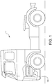
- a vehicle 1 in the form of a truck comprises an engine 100 in the form of an internal combustion engine arrangement 100 as will be described further below in relation to the description of e.g. Figs. 2 and 3 .
- the internal combustion engine arrangement 100 is preferably propelled by e.g. a conventional fuel such as diesel.
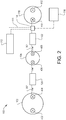
- the internal combustion engine arrangement 100 comprises a compression cylinder 102.
- the compression cylinder 102 comprises a reciprocating compression piston (not shown), i.e. the reciprocating compression piston is housed within the compression cylinder 102 to operate in a reciprocating motion between an upper end, also commonly referred to as top dead center (TDC) and a lower end, also commonly referred to as bottom dead center (BDC).
- the compression cylinder 102 further comprises an inlet valve 402 at which gas, preferably in the form of air at ambient gas pressure is controllably provided into the compression cylinder 402.
- the compression cylinder 102 also comprises an outlet valve 404 through which compressed gas is controllably exhausted from the compression cylinder 102.
- the compression cylinder 102 is preferably operated in a two stroke fashion.
- the internal combustion engine arrangement 100 comprises a combustion cylinder 106 arranged in downstream fluid communication with the compression cylinder 102, via a conduit 302.
- the combustion cylinder 106 comprises a reciprocating piston (not shown), i.e. the reciprocating combustion piston is housed within the combustion cylinder 106 to operate in a reciprocating motion between the TDC and the BDC of the combustion cylinder.
- the combustion cylinder 106 further comprises an inlet valve 406, at which compressed gas from the compression cylinder 102 is controllably provided into the combustion cylinder 106.
- the combustion cylinder 106 further comprises an outlet valve 408 through which compressed combustion gas is exhausted from the combustion cylinder 106.
- the combustion cylinder 106 is preferably operated in a four stroke fashion.
- the combustion cylinder 106 comprises a fuel injection system (not shown) for providing fuel into the combustion cylinder 106 for combustion therein.
- the internal combustion engine arrangement 100 comprises an expansion cylinder 110 arranged in downstream fluid communication with the combustion cylinder 106 via a conduit 304.
- the expansion cylinder 110 comprises a reciprocating expansion piston (not shown), i.e. the reciprocating expansion piston is housed within the expansion cylinder 110 to operate in a reciprocating motion between the TDC and the BDC of the expansion cylinder.
- the expansion cylinder 110 further comprises an inlet valve 410, at which compressed combustion gas from the combustion cylinder 106 is controllably provided into the expansion cylinder 110.
- the expansion cylinder 110 further comprises an outlet valve 412 through which expanded combustion gas is exhausted from the expansion cylinder 110 to an aftertreatment system (not shown) or the like.
- the internal combustion engine arrangement 100 comprises a pressure tank 112.
- the pressure tank 112 is arranged in fluid communication with the expansion cylinder 112 via a pressure tank conduit 111.
- the pressure tank 112 is arranged to controllably receive compressed gas from the expansion cylinder 110, and to controllably deliver compressed gas to the expansion cylinder 110, in dependence of a current operating mode of the internal combustion engine arrangement 100.
- the pressure tank 112 should be designed to withstand gas pressure levels corresponding to at least the gas pressure level of the compressed gas generated in the expansion cylinder 110.
- the internal combustion arrangement 100 comprises a valve arrangement 114.
- the valve arrangement 114 is preferably a three-way valve arrangement connected in fluid communication with the combustion cylinder 106, the expansion cylinder 110 and the pressure tank 112.
- the valve arrangement 114 is also connected to a control unit 116 for controlling the valve arrangement 114.
- the valve arrangement 114, and its positions controlled by the control unit 116 will be described in further detail below in relation to the description of Figs. 3a - 3c .
- the internal combustion engine arrangement 100 comprises a first 120 and a second 122 intermediate tank.
- the first intermediate tank 120 is positioned in the conduit 302 and thus arranged in fluid communication between the compression cylinder 102 and the combustion cylinder 106.
- the first intermediate tank 120 may also be referred to as an intermediate low pressure gas tank.
- the second intermediate tank 122 is positioned in the conduit 304 and thus arranged in fluid communication between the combustion cylinder 106 and the expansion cylinder 110, or more precisely in fluid communication between the combustion cylinder 106 and the valve arrangement 114.
- the second intermediate tank 122 may also be referred to as an intermediate high pressure gas tank as the pressure level of the gas contained therein is higher than the pressure level of the gas contained in the first intermediate tank 120.
- first 120 and/or second 122 intermediate tanks are additional components that may be incorporated if desired. Hence, it may not be necessary to include the first 120 and/or second 122 intermediate tanks to the internal combustion engine arrangement for the functioning of controlling the internal combustion engine in the various modes described below.
- Air is provided into the compression cylinder 102 via the inlet valve 402 of the compression cylinder 102.
- the air is compressed in a two stroke fashion before being exhausted to the conduit 302 via the outlet valve 404.
- the compressed air is directed into the first intermediate tank 120 and thereafter directed into the combustion cylinder 106 via the inlet valve 406 of the combustion cylinder 106.
- the compressed air is even further compressed and combustible fuel is injected into the combustion chamber of the combustion cylinder 106.
- the compressed combustion gas is, after combustion, directed into the conduit 304 via the outlet valve 408 of the combustion cylinder and further directed into the second intermediate tank 122.
- the compressed combustion gas is thereafter directed into the expansion cylinder 110 via the inlet valve 410 of the expansion cylinder 110.
- the compressed combustion gas is, during the reciprocating two stroke motion of the expansion cylinder expanded and directed out from the expansion cylinder 110 via the outlet valve 412.
- the compression piston, the combustion piston and the expansion piston are connected to the crankshaft (not shown) of the internal combustion engine arrangement 100.
- the compression piston, the combustion piston and the expansion piston may be directly connected to one and the same crankshaft or connected to the crank shaft via an intermediate crankshaft or the like, which in turn is/are connected to the crankshaft via e.g. gear wheels in meshed connection with each other.
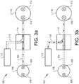
- FIGs. 3a ⁇ 3c illustrate three different operating modes for the internal combustion engine arrangement 100 according to example embodiments thereof.
- Figs. 3a ⁇ 3c schematically illustrate how the valve arrangement 114 is arranged to direct flow of gas for the various operating modes.
- the compression cylinder 102, the first 120 and second 122 intermediate tanks, as well as the control unit 116 have been omitted for simplifying the illustration and understanding of the gas flow.
- the valve arrangement 114 has been schematically depicted in each of Figs. 3a ⁇ 3b by focusing on the flow direction.
- the valve arrangement 114 may thus be designed in different forms as long as being controllable according to the below description.
- Fig. 3a illustrate the above described normal operation of the internal combustion arrangement 100.
- the valve arrangement 114 is arranged in a normal operating position where compressed gas is delivered from the outlet valve 408 of the combustion cylinder 106 and directed into the expansion cylinder 110 via the conduit 304 and the inlet valve 410 of the expansion cylinder 110.
- the valve arrangement 114 is preventing compressed gas to be delivered to the pressure tank 112.
- the internal combustion engine arrangement 100 is however also arranged to assume a first operating mode and a second operating mode. Reference is therefore made to Fig. 3b which illustrates the flow of compressed gas in the first operating mode.
- the internal combustion engine arrangement 100 is preferably arranged to be operated in the first operating mode when the vehicle is exposed to engine braking.
- the main target of the first operating mode is to provide compressed gas generated in the expansion cylinder 110 into the pressure tank 112. As can be seen in Fig. 3b , this is accomplished by positioning the valve arrangement in a first operating position allowing compressed gas to be delivered from the expansion cylinder 110 into the pressure tank 112.
- the expansion cylinder 110 receives gas in the form of ambient air, preferably through the outlet valve 412.
- the air/gas is compressed in the expansion cylinder 110 by means of the reciprocating motion of the expansion cylinder.
- the expansion cylinder 110 then acts as an air/gas pump for pumping the compressed gas from the expansion cylinder 110 into the pressure tank 112 via the pressure tank conduit 111.
- the valve arrangement 114 prevents flow of gas from the combustion cylinder 106 to the expansion cylinder 110, while allowing flow of compressed gas to be delivered from the expansion cylinder 110 and into the pressure tank 112.
- the internal combustion engine arrangement 100 can be arranged to assume the second operating mode.
- the second operating mode may also be referred to as an air hybrid mode. This is due to the fact that the internal combustion engine arrangement 100 will be operated by means of compressed gas from the pressure tank 112.
- the internal combustion engine arrangement 100 is preferably operated in the second operating mode when there is a desire to add additional power to the vehicle, such as for assisting an electric motor, etc.
- Fig. 3c illustrates the flow of compressed gas when the internal combustion engine arrangement 100 assumes the second operating mode.
- the valve arrangement 114 is positioned in the first operating position allowing compressed gas to be delivered from the pressure tank 112 to the expansion cylinder 110.
- the compressed gas from the pressure tank 112 propels the internal combustion engine arrangement 100 by forcing the expansion piston to reciprocate within the expansion cylinder 110.
- the expansion piston is connected to the crankshaft, propulsion of the internal combustion engine is achieved by forcing the expansion piston to reciprocate within the expansion cylinder 110.
- the second operating positon of the valve arrangement 114 prevents compressed gas from the combustion cylinder 106 to be delivered to the expansion cylinder 110.
- opening and closing timing of the inlet valve 410 of the expansion cylinder can be adjusted to allow more/less compressed gas therein.
- the first operating position of the valve arrangement 114 thus allows the flow of gas both to and from the pressure tank.
- Fig. 4 illustrates another example embodiment of the internal combustion engine arrangement 100.
- the embodiment in Fig. 4 comprises a heat regenerator 140.
- the heat regenerator 140 is arranged in the pressure tank conduit 111 in fluid communication between the valve arrangement 114 and the pressure tank 112.
- the valve arrangement 114 is in Fig. 4 arranged to assume the different positions as described above in relation to the description of Figs. 3a ⁇ 3c.
- the flow direction in Fig. 4 is therefore illustrated by means of double sided arrows.
- flow is directed from the valve arrangement 114 to the pressure tank 112, via the heat regenerator 140, as depicted in Fig.
- the heat regenerator 140 comprises a warm side 142 illustrated by a flame, and a cold side 144 illustrated by a snow flake.
- relatively warm compressed gas is directed from the combustion cylinder 106 to the pressure tank 112 via the heat regenerator 140.
- the heat regenerator 140 absorbs the heat in the compressed combustion gas such that the compressed gas delivered to the pressure tank 112 is substantially at ambient temperature.
- the heat regenerator 140 thus absorbs the heat and "keeps" the heat until the internal combustion engine 100 assumes the second operating mode.
- the compressed gas in the pressure tank 112 is directed towards the valve unit 114 as depicted in Fig. 3c .
- the compressed gas passes the heat regenerator 140, i.e.
- the gas travels along the heat regenerator 140, the thermal energy is released and transported with the compressed gas flow towards the expansion cylinder 110.
- the heat regenerator 140 By means of the heat regenerator 140, a substantially reversible process is achieved.
- the compressed gas leaving the heat regenerator 140 in the second operating mode will have substantially the same temperature as the temperature of the compressed gas that entered the heat regenerator in the first operating mode.
- the heat regenerator 140 When compressed gas is delivered from the pressure tank 112 to the expansion cylinder 110, the heat wave is moved away from the pressure tank 112 as indicated by the dotted wave with numeral 154. There is thus a heat gradient in the heat regenerator 140, whereby a heat wave is formed when directing compressed gas to and from the pressure tank 112, which is caused by the relatively high energy utilization of the internal combustion engine arrangement 100.
- the heat regenerator should have a relatively steep heat wave, i.e. a relatively steep heat gradient, whereby the temperature of the compressed gas is reduced relatively quickly when entering the heat regenerator 140. This will prevent the heat from leaking from the heat regenerator 140.
- the thermal conductivity of the heat regenerator 140 should preferably be relatively low in the flow direction of the compressed gas.
- the heat regenerator 140 should preferably be provided with suitable heat insulation (not shown).
- an operating state of the vehicle 1 is determined S1. It is thereafter determined if the vehicle is operated in the first operating state or the second operating state.
- the first operating state preferably corresponds to an engine braking operation of the vehicle, while the second operating state preferably corresponds to a driving state where the vehicle is in need of an increased engine power for a shorter period of time.
- compressed gas generated in the expansion cylinder 110 is controlled S2 to be directed to the pressure tank 112.
- the compressed gas is directed to the pressure tank 112 via the above described heat regenerator 140 such that heat in the compressed gas is absorbed in the heat regenerator 140 before delivery to the pressure tank 112.
- the compressed gas contained in the pressure tank 112 is controlled S3 to be delivered from the pressure tank 112 to the expansion cylinder 110.
- the compressed gas is directed to the expansion cylinder 110 via the heat regenerator 140 for heating the compressed gas before delivery to the expansion cylinder 110.
- the internal combustion engine arrangement 100 may be controlled S4 to direct compressed gas from the combustion cylinder to the expansion cylinder as depicted and described above in relation to Fig. 3a .
- the internal combustion engine arrangement 100 comprising a single compression cylinder 102, a single combustion cylinder 106 and a single expansion cylinder 110
- two compression cylinders, two combustion cylinders and two expansion cylinders may also equally as well be used.
- Another alternative is to use a single compression cylinder, a single expansion cylinder and two combustion cylinders.
- a still further alternative is to use dual compression cylinders, dual combustion cylinders, dual expansion cylinders, wherein an additional compression cylinder is arranged in fluid communication between the dual compression cylinders and the dual combustion cylinders.
- the flow of gas to/from the pressure tank can be controlled by controlling the outlet valves of the combustion cylinders.
- the outlet valves of the combustion cylinders can be kept close while delivering compressed gas to/from the pressure tank.
Landscapes
- Engineering & Computer Science (AREA)
- Chemical & Material Sciences (AREA)
- Combustion & Propulsion (AREA)
- Mechanical Engineering (AREA)
- General Engineering & Computer Science (AREA)
- Output Control And Ontrol Of Special Type Engine (AREA)
Claims (15)
- Verbrennungsmotoranordnung (100) für ein Fahrzeug (1), wobei die Verbrennungsmotoranordnung (100) einen Verbrennungszylinder (106), in dem ein Hubkolben untergebracht ist, und einen Expansionszylinder (110), in dem ein Expansionshubkolben untergebracht ist, umfasst, wobei der Expansionszylinder (110) in nachgeschalteter Fluidverbindung mit dem Verbrennungszylinder (106) angeordnet ist, um aus dem Verbrennungszylinder (106) ausgestoßene Verbrennungsgase aufzunehmen, dadurch gekennzeichnet, dass die Verbrennungsmotoranordnung (100) ferner einen Drucktank (112) umfasst, der in Fluidverbindung mit dem Expansionszylinder (110) angeordnet ist, wobei die Verbrennungsmotoranordnung (100) ferner angeordnet ist, um in einem ersten Betriebsmodus betrieben zu werden, in dem der Expansionszylinder angeordnet ist, um als eine Pumpe zum Komprimieren von Gas in dem Expansionszylinder (110) betrieben zu werden, wobei das komprimierte Gas zu dem Drucktank (112) geliefert wird, und in einem zweiten Betriebsmodus, in dem komprimiertes Gas, das in dem Drucktank (112) enthalten ist, von dem Drucktank (112) zu dem Expansionszylinder (110) geliefert wird.
- Verbrennungsmotoranordnung nach Anspruch 1, wobei der Expansionszylinder (110) angeordnet ist, um Umgebungsluft zu komprimieren und komprimierte Umgebungsluft zu dem Drucktank (112) zu pumpen, wenn die Verbrennungsmotoranordnung in dem ersten Betriebsmodus betrieben wird.
- Verbrennungsmotoranordnung nach einem der Ansprüche 1 oder 2, wobei verhindert wird, dass Verbrennungsgas aus dem Verbrennungszylinder (106) zum Expansionszylinder (110) geleitet wird, wenn die Verbrennungsmotoranordnung (100) in dem zweiten Betriebsmodus betrieben wird.
- Verbrennungsmotoranordnung nach einem der vorhergehenden Ansprüche, ferner umfassend eine Steuereinheit (116) zum selektiven Steuern des Verbrennungsmotors, um entweder in dem ersten oder dem zweiten Betriebsmodus betrieben zu werden.
- Verbrennungsmotoranordnung nach Anspruch 4, wobei die Steuereinheit konfiguriert ist, um:- ein Signal zu empfangen, das einen Bremsvorgang für das Fahrzeug (1) anzeigt; und- die Verbrennungsmotoranordnung (100) so zu steuern, dass sie in dem ersten Betriebsmodus betrieben wird, wenn das Fahrzeug dem Bremsvorgang ausgesetzt ist.
- Verbrennungsmotoranordnung nach einem der Ansprüche 4 oder 5, wobei die Steuereinheit (116) ferner konfiguriert ist, um:- ein Signal zu empfangen, das einen für das Fahrzeug (1) erforderliches Leistungsniveau anzeigt,- das erforderliche Leistungsniveau mit einem vorgegebenen Schwellenwert zu vergleichen; und- die Verbrennungsmotoranordnung so zu steuern, dass sie in dem zweiten Betriebsmodus betrieben wird, wenn das erforderliche Leistungsniveau den vorgegebenen Grenzwert überschreitet.
- Verbrennungsmotoranordnung nach einem der vorhergehenden Ansprüche, ferner umfassend einen Zwischentank (122), der in Fluidverbindung zwischen dem Verbrennungszylinder (106) und dem Expansionszylinder (110) angeordnet ist, wobei der Zwischentank (122) so angeordnet ist, dass er komprimiertes Gas enthält, das aus dem Verbrennungszylinder (106) ausgestoßen wird.
- Verbrennungsmotoranordnung nach einem der vorhergehenden Ansprüche, ferner umfassend einen Wärmeregenerator (140), der in Fluidverbindung zwischen dem Expansionszylinder (110) und dem Drucktank (112) angeordnet ist, wobei der Wärmeregenerator so angeordnet ist, dass er Wärme aus dem vom Expansionszylinder (110) erzeugten komprimierten Gas absorbiert.
- Verbrennungsmotoranordnung nach einem der vorhergehenden Ansprüche, ferner umfassend einen Kompressionszylinder (102), in dem ein Hubkolben untergebracht ist, wobei der Kompressionszylinder (102) in vorgeschalteter Fluidverbindung mit dem Verbrennungszylinder (106) zur Zuführung von Druckluft zum Verbrennungszylinder angeordnet ist.
- Verfahren zum Steuern einer Verbrennungsmotoranordnung, wobei die Verbrennungsmotoranordnung einen Verbrennungszylinder, in dem ein Hubkolben untergebracht ist, und einen Expansionszylinder, in dem Expansionshubkolben untergebracht ist, wobei der Expansionszylinder in nachgeschalteter Fluidverbindung mit dem Verbrennungszylinder angeordnet ist, um aus dem Verbrennungszylinder ausgestoßene Verbrennungsgase aufzunehmen, und einen Drucktank umfasst, der in Fluidverbindung mit dem Expansionszylinder angeordnet ist, wobei das Verfahren durch die folgenden Schritte gekennzeichnet ist:- Bestimmen (S1) eines Betriebszustands des Fahrzeugs;wenn das Fahrzeug in einem ersten Betriebszustand betrieben wird:- Steuern (S2) des im Expansionszylinder erzeugten Druckgases, das zum Drucktank geleitet werden soll; undwenn das Fahrzeug in einem zweiten Betriebszustand betrieben wird:- Steuern (S3) des im Drucktank enthaltenen Druckgases, das an den Expansionszylinder geliefert werden soll.
- Fahrzeug (1), das eine Verbrennungsmotoranordnung nach einem der Ansprüche 1-9 umfasst.
- Fahrzeug nach Anspruch 11, ferner umfassend eine zweite Antriebsmaschine, die sich von der Verbrennungsmotoranordnung unterscheidet, wobei das Fahrzeug konfiguriert ist für den Betrieb in:- einem ersten Fahrzeugzustand, in dem das Fahrzeug durch Zuführung von Druckgas aus dem Drucktank zum Expansionszylinder angetrieben wird; und- einem zweiten Fahrzeugzustand, in dem das Fahrzeug unter Verwendung der zweiten Antriebsmaschine angetrieben wird.
- Fahrzeug nach Anspruch 12, wobei das Fahrzeug im ersten Fahrzeugzustand betrieben wird, wenn der Leistungsbedarf des Fahrzeugs im Vergleich zum Betrieb im zweiten Fahrzeugzustand höher ist.
- Computerprogramm mit Programmcodemitteln zur Durchführung der Schritte nach Anspruch 10, wenn das Programm auf einem Computer ausgeführt wird.
- Computerlesbares Medium mit einem Computerprogramm, das Programmmittel zum Durchführen der Schritte nach Anspruch 10 umfasst, wenn das Programmmittel auf einem Computer ausgeführt wird.
Applications Claiming Priority (1)
| Application Number | Priority Date | Filing Date | Title |
|---|---|---|---|
| PCT/EP2017/072129 WO2019042575A1 (en) | 2017-09-04 | 2017-09-04 | INTERNAL COMBUSTION ENGINE ARRANGEMENT |
Publications (2)
| Publication Number | Publication Date |
|---|---|
| EP3679231A1 EP3679231A1 (de) | 2020-07-15 |
| EP3679231B1 true EP3679231B1 (de) | 2021-11-03 |
Family
ID=59772622
Family Applications (1)
| Application Number | Title | Priority Date | Filing Date |
|---|---|---|---|
| EP17761501.0A Active EP3679231B1 (de) | 2017-09-04 | 2017-09-04 | Verbrennungsmotoranordnung |
Country Status (4)
| Country | Link |
|---|---|
| US (1) | US11085368B2 (de) |
| EP (1) | EP3679231B1 (de) |
| CN (1) | CN111065804B (de) |
| WO (1) | WO2019042575A1 (de) |
Family Cites Families (26)
| Publication number | Priority date | Publication date | Assignee | Title |
|---|---|---|---|---|
| US967828A (en) * | 1906-08-14 | 1910-08-16 | C P Power Company | Compound internal-combustion engine. |
| US4512154A (en) * | 1971-09-22 | 1985-04-23 | Takahiro Ueno | Method for driving a vehicle driven by an internal combustion engine |
| US4211083A (en) * | 1971-09-22 | 1980-07-08 | Takahiro Ueno | Method for driving a vehicle driven by an internal combustion engine |
| US3958900A (en) * | 1973-06-11 | 1976-05-25 | Takahiro Ueno | Convertible engine-air compressor apparatus mounted on a vehicle for driving said vehicle |
| US4040400A (en) | 1975-09-02 | 1977-08-09 | Karl Kiener | Internal combustion process and engine |
| US4565167A (en) * | 1981-12-08 | 1986-01-21 | Bryant Clyde C | Internal combustion engine |
| BE1000774A5 (fr) * | 1987-07-30 | 1989-04-04 | Schmitz Gerhard | Moteur a combustion interne a six temps. |
| US4783966A (en) * | 1987-09-01 | 1988-11-15 | Aldrich Clare A | Multi-staged internal combustion engine |
| US5638681A (en) * | 1992-07-17 | 1997-06-17 | Rapp; Manfred Max | Piston internal-combustion engine |
| IL121446A (en) * | 1997-07-31 | 2000-12-06 | Krauss Otto Israel | Supercharged internal combustion compound engine |
| GB0007917D0 (en) * | 2000-03-31 | 2000-05-17 | Npower | An engine |
| GB2428653B (en) | 2005-08-05 | 2010-02-24 | Thomas Tsoi Hei Ma | Air hybrid vehicle |
| US7353786B2 (en) * | 2006-01-07 | 2008-04-08 | Scuderi Group, Llc | Split-cycle air hybrid engine |
| US8657046B2 (en) | 2007-12-03 | 2014-02-25 | Caudill Energy Systems, Corporation | Engine system |
| CN101307718A (zh) * | 2008-03-29 | 2008-11-19 | 王汉全 | 二次膨胀混合冲程内燃发动机 |
| US8412441B1 (en) | 2009-09-09 | 2013-04-02 | Sturman Digital Systems, Llc | Mixed cycle compression ignition engines and methods |
| SE534436C2 (sv) | 2010-06-24 | 2011-08-23 | Cargine Engineering Ab | Förbränningsmotor för ett fordon innefattande åtminstone en kompressorcylinder förbunden med en tryckluftstank |
| US20120090580A1 (en) * | 2010-10-15 | 2012-04-19 | Lung Tan Hu | Controlled-compression direct-power-cycle engine |
| US20120255296A1 (en) * | 2011-04-08 | 2012-10-11 | Scuderi Group, Llc | Air management system for air hybrid engine |
| US8607566B2 (en) * | 2011-04-15 | 2013-12-17 | GM Global Technology Operations LLC | Internal combustion engine with emission treatment interposed between two expansion phases |
| US9297295B2 (en) * | 2013-03-15 | 2016-03-29 | Scuderi Group, Inc. | Split-cycle engines with direct injection |
| WO2015090341A1 (en) | 2013-12-19 | 2015-06-25 | Volvo Truck Corporation | An internal combustion engine |
| CN105829678B (zh) * | 2013-12-19 | 2019-10-11 | 沃尔沃卡车集团 | 内燃机 |
| WO2017101965A1 (en) * | 2015-12-14 | 2017-06-22 | Volvo Truck Corporation | An internal combustion engine system and a method for an internal combustion engine system |
| US10774712B2 (en) * | 2015-12-14 | 2020-09-15 | Volvo Truck Corporation | Internal combustion engine system and an exhaust treatment unit for such a system |
| CN106089409B (zh) * | 2016-06-15 | 2019-06-28 | 徐小山 | 一种活塞往复式发动机 |
-
2017
- 2017-09-04 WO PCT/EP2017/072129 patent/WO2019042575A1/en not_active Ceased
- 2017-09-04 EP EP17761501.0A patent/EP3679231B1/de active Active
- 2017-09-04 US US16/638,575 patent/US11085368B2/en not_active Expired - Fee Related
- 2017-09-04 CN CN201780094335.6A patent/CN111065804B/zh active Active
Also Published As
| Publication number | Publication date |
|---|---|
| US20200217244A1 (en) | 2020-07-09 |
| WO2019042575A1 (en) | 2019-03-07 |
| CN111065804A (zh) | 2020-04-24 |
| EP3679231A1 (de) | 2020-07-15 |
| US11085368B2 (en) | 2021-08-10 |
| CN111065804B (zh) | 2021-11-09 |
Similar Documents
| Publication | Publication Date | Title |
|---|---|---|
| CN1099523C (zh) | 注入附加空气的发动机的加热方法和装置 | |
| RU2622457C1 (ru) | Двигатель внутреннего сгорания на основе изотермического сжатия, способ его работы и его управления | |
| JP2010539384A (ja) | 固定カムシャフトに基づく空気圧ハイブリッド内燃機関 | |
| CA2660578A1 (en) | Improved compressed-air or gas and/or additional-energy engine having an active expansion chamber | |
| US11512654B2 (en) | Method for controlling injection in a combustion engine | |
| US12172513B2 (en) | Gas tank arrangement | |
| US9074588B2 (en) | Air compression method and apparatus | |
| US20130180498A1 (en) | High-pressure spark and stratification ignition device for an internal combustion engine | |
| US10955088B2 (en) | Fuel tank arrangement with a gas burning arrangement and a pressure controlled valve to heat auxiliary vehicle components | |
| CN103925071A (zh) | 车用活塞式多功能发动机 | |
| US11725572B2 (en) | Method and system for an on board compressor | |
| EP3679231B1 (de) | Verbrennungsmotoranordnung | |
| CN110087929A (zh) | 用于运行驱动系统的方法、驱动系统和机动车 | |
| US20040040305A1 (en) | One cycle internal combustion engine | |
| US11773793B2 (en) | Method and system for compressed air supply | |
| RU127823U1 (ru) | Система жидкостного охлаждения двигателя внутреннего сгорания и отопления салона транспортного средства | |
| RU78733U1 (ru) | Система жидкостного охлаждения двигателя внутреннего сгорания и отопления салона транспортного средства (варианты) | |
| CN103967587A (zh) | 分缸式二级压缩发动机 | |
| US11852045B2 (en) | Method for controlling an internal combustion engine arrangement | |
| US8690548B1 (en) | Mobile heat pump | |
| US20230250752A1 (en) | Method and system for compressed air supply | |
| JP2022080290A (ja) | 内燃機関および車両 | |
| JPH0357564Y2 (de) | ||
| Golovchuk et al. | Free-piston engine-and-hydraulic pump for railway vehicles | |
| CN103925082A (zh) | 二级压缩内燃机 |
Legal Events
| Date | Code | Title | Description |
|---|---|---|---|
| STAA | Information on the status of an ep patent application or granted ep patent |
Free format text: STATUS: UNKNOWN |
|
| STAA | Information on the status of an ep patent application or granted ep patent |
Free format text: STATUS: THE INTERNATIONAL PUBLICATION HAS BEEN MADE |
|
| PUAI | Public reference made under article 153(3) epc to a published international application that has entered the european phase |
Free format text: ORIGINAL CODE: 0009012 |
|
| STAA | Information on the status of an ep patent application or granted ep patent |
Free format text: STATUS: REQUEST FOR EXAMINATION WAS MADE |
|
| 17P | Request for examination filed |
Effective date: 20200218 |
|
| AK | Designated contracting states |
Kind code of ref document: A1 Designated state(s): AL AT BE BG CH CY CZ DE DK EE ES FI FR GB GR HR HU IE IS IT LI LT LU LV MC MK MT NL NO PL PT RO RS SE SI SK SM TR |
|
| AX | Request for extension of the european patent |
Extension state: BA ME |
|
| DAV | Request for validation of the european patent (deleted) | ||
| DAX | Request for extension of the european patent (deleted) | ||
| GRAP | Despatch of communication of intention to grant a patent |
Free format text: ORIGINAL CODE: EPIDOSNIGR1 |
|
| STAA | Information on the status of an ep patent application or granted ep patent |
Free format text: STATUS: GRANT OF PATENT IS INTENDED |
|
| INTG | Intention to grant announced |
Effective date: 20210528 |
|
| GRAS | Grant fee paid |
Free format text: ORIGINAL CODE: EPIDOSNIGR3 |
|
| GRAA | (expected) grant |
Free format text: ORIGINAL CODE: 0009210 |
|
| STAA | Information on the status of an ep patent application or granted ep patent |
Free format text: STATUS: THE PATENT HAS BEEN GRANTED |
|
| AK | Designated contracting states |
Kind code of ref document: B1 Designated state(s): AL AT BE BG CH CY CZ DE DK EE ES FI FR GB GR HR HU IE IS IT LI LT LU LV MC MK MT NL NO PL PT RO RS SE SI SK SM TR |
|
| REG | Reference to a national code |
Ref country code: GB Ref legal event code: FG4D |
|
| REG | Reference to a national code |
Ref country code: AT Ref legal event code: REF Ref document number: 1444136 Country of ref document: AT Kind code of ref document: T Effective date: 20211115 Ref country code: CH Ref legal event code: EP |
|
| REG | Reference to a national code |
Ref country code: IE Ref legal event code: FG4D |
|
| REG | Reference to a national code |
Ref country code: DE Ref legal event code: R096 Ref document number: 602017048736 Country of ref document: DE |
|
| REG | Reference to a national code |
Ref country code: LT Ref legal event code: MG9D |
|
| REG | Reference to a national code |
Ref country code: NL Ref legal event code: MP Effective date: 20211103 |
|
| REG | Reference to a national code |
Ref country code: AT Ref legal event code: MK05 Ref document number: 1444136 Country of ref document: AT Kind code of ref document: T Effective date: 20211103 |
|
| PG25 | Lapsed in a contracting state [announced via postgrant information from national office to epo] |
Ref country code: RS Free format text: LAPSE BECAUSE OF FAILURE TO SUBMIT A TRANSLATION OF THE DESCRIPTION OR TO PAY THE FEE WITHIN THE PRESCRIBED TIME-LIMIT Effective date: 20211103 Ref country code: LT Free format text: LAPSE BECAUSE OF FAILURE TO SUBMIT A TRANSLATION OF THE DESCRIPTION OR TO PAY THE FEE WITHIN THE PRESCRIBED TIME-LIMIT Effective date: 20211103 Ref country code: FI Free format text: LAPSE BECAUSE OF FAILURE TO SUBMIT A TRANSLATION OF THE DESCRIPTION OR TO PAY THE FEE WITHIN THE PRESCRIBED TIME-LIMIT Effective date: 20211103 Ref country code: BG Free format text: LAPSE BECAUSE OF FAILURE TO SUBMIT A TRANSLATION OF THE DESCRIPTION OR TO PAY THE FEE WITHIN THE PRESCRIBED TIME-LIMIT Effective date: 20220203 Ref country code: AT Free format text: LAPSE BECAUSE OF FAILURE TO SUBMIT A TRANSLATION OF THE DESCRIPTION OR TO PAY THE FEE WITHIN THE PRESCRIBED TIME-LIMIT Effective date: 20211103 |
|
| PG25 | Lapsed in a contracting state [announced via postgrant information from national office to epo] |
Ref country code: IS Free format text: LAPSE BECAUSE OF FAILURE TO SUBMIT A TRANSLATION OF THE DESCRIPTION OR TO PAY THE FEE WITHIN THE PRESCRIBED TIME-LIMIT Effective date: 20220303 Ref country code: SE Free format text: LAPSE BECAUSE OF FAILURE TO SUBMIT A TRANSLATION OF THE DESCRIPTION OR TO PAY THE FEE WITHIN THE PRESCRIBED TIME-LIMIT Effective date: 20211103 Ref country code: PT Free format text: LAPSE BECAUSE OF FAILURE TO SUBMIT A TRANSLATION OF THE DESCRIPTION OR TO PAY THE FEE WITHIN THE PRESCRIBED TIME-LIMIT Effective date: 20220303 Ref country code: PL Free format text: LAPSE BECAUSE OF FAILURE TO SUBMIT A TRANSLATION OF THE DESCRIPTION OR TO PAY THE FEE WITHIN THE PRESCRIBED TIME-LIMIT Effective date: 20211103 Ref country code: NO Free format text: LAPSE BECAUSE OF FAILURE TO SUBMIT A TRANSLATION OF THE DESCRIPTION OR TO PAY THE FEE WITHIN THE PRESCRIBED TIME-LIMIT Effective date: 20220203 Ref country code: NL Free format text: LAPSE BECAUSE OF FAILURE TO SUBMIT A TRANSLATION OF THE DESCRIPTION OR TO PAY THE FEE WITHIN THE PRESCRIBED TIME-LIMIT Effective date: 20211103 Ref country code: LV Free format text: LAPSE BECAUSE OF FAILURE TO SUBMIT A TRANSLATION OF THE DESCRIPTION OR TO PAY THE FEE WITHIN THE PRESCRIBED TIME-LIMIT Effective date: 20211103 Ref country code: HR Free format text: LAPSE BECAUSE OF FAILURE TO SUBMIT A TRANSLATION OF THE DESCRIPTION OR TO PAY THE FEE WITHIN THE PRESCRIBED TIME-LIMIT Effective date: 20211103 Ref country code: GR Free format text: LAPSE BECAUSE OF FAILURE TO SUBMIT A TRANSLATION OF THE DESCRIPTION OR TO PAY THE FEE WITHIN THE PRESCRIBED TIME-LIMIT Effective date: 20220204 Ref country code: ES Free format text: LAPSE BECAUSE OF FAILURE TO SUBMIT A TRANSLATION OF THE DESCRIPTION OR TO PAY THE FEE WITHIN THE PRESCRIBED TIME-LIMIT Effective date: 20211103 |
|
| PG25 | Lapsed in a contracting state [announced via postgrant information from national office to epo] |
Ref country code: SM Free format text: LAPSE BECAUSE OF FAILURE TO SUBMIT A TRANSLATION OF THE DESCRIPTION OR TO PAY THE FEE WITHIN THE PRESCRIBED TIME-LIMIT Effective date: 20211103 Ref country code: SK Free format text: LAPSE BECAUSE OF FAILURE TO SUBMIT A TRANSLATION OF THE DESCRIPTION OR TO PAY THE FEE WITHIN THE PRESCRIBED TIME-LIMIT Effective date: 20211103 Ref country code: RO Free format text: LAPSE BECAUSE OF FAILURE TO SUBMIT A TRANSLATION OF THE DESCRIPTION OR TO PAY THE FEE WITHIN THE PRESCRIBED TIME-LIMIT Effective date: 20211103 Ref country code: EE Free format text: LAPSE BECAUSE OF FAILURE TO SUBMIT A TRANSLATION OF THE DESCRIPTION OR TO PAY THE FEE WITHIN THE PRESCRIBED TIME-LIMIT Effective date: 20211103 Ref country code: DK Free format text: LAPSE BECAUSE OF FAILURE TO SUBMIT A TRANSLATION OF THE DESCRIPTION OR TO PAY THE FEE WITHIN THE PRESCRIBED TIME-LIMIT Effective date: 20211103 Ref country code: CZ Free format text: LAPSE BECAUSE OF FAILURE TO SUBMIT A TRANSLATION OF THE DESCRIPTION OR TO PAY THE FEE WITHIN THE PRESCRIBED TIME-LIMIT Effective date: 20211103 |
|
| REG | Reference to a national code |
Ref country code: DE Ref legal event code: R097 Ref document number: 602017048736 Country of ref document: DE |
|
| PLBE | No opposition filed within time limit |
Free format text: ORIGINAL CODE: 0009261 |
|
| STAA | Information on the status of an ep patent application or granted ep patent |
Free format text: STATUS: NO OPPOSITION FILED WITHIN TIME LIMIT |
|
| 26N | No opposition filed |
Effective date: 20220804 |
|
| PG25 | Lapsed in a contracting state [announced via postgrant information from national office to epo] |
Ref country code: AL Free format text: LAPSE BECAUSE OF FAILURE TO SUBMIT A TRANSLATION OF THE DESCRIPTION OR TO PAY THE FEE WITHIN THE PRESCRIBED TIME-LIMIT Effective date: 20211103 |
|
| PG25 | Lapsed in a contracting state [announced via postgrant information from national office to epo] |
Ref country code: SI Free format text: LAPSE BECAUSE OF FAILURE TO SUBMIT A TRANSLATION OF THE DESCRIPTION OR TO PAY THE FEE WITHIN THE PRESCRIBED TIME-LIMIT Effective date: 20211103 |
|
| PG25 | Lapsed in a contracting state [announced via postgrant information from national office to epo] |
Ref country code: MC Free format text: LAPSE BECAUSE OF FAILURE TO SUBMIT A TRANSLATION OF THE DESCRIPTION OR TO PAY THE FEE WITHIN THE PRESCRIBED TIME-LIMIT Effective date: 20211103 |
|
| REG | Reference to a national code |
Ref country code: CH Ref legal event code: PL |
|
| GBPC | Gb: european patent ceased through non-payment of renewal fee |
Effective date: 20220904 |
|
| REG | Reference to a national code |
Ref country code: BE Ref legal event code: MM Effective date: 20220930 |
|
| PG25 | Lapsed in a contracting state [announced via postgrant information from national office to epo] |
Ref country code: IT Free format text: LAPSE BECAUSE OF FAILURE TO SUBMIT A TRANSLATION OF THE DESCRIPTION OR TO PAY THE FEE WITHIN THE PRESCRIBED TIME-LIMIT Effective date: 20211103 |
|
| PG25 | Lapsed in a contracting state [announced via postgrant information from national office to epo] |
Ref country code: LU Free format text: LAPSE BECAUSE OF NON-PAYMENT OF DUE FEES Effective date: 20220904 |
|
| PG25 | Lapsed in a contracting state [announced via postgrant information from national office to epo] |
Ref country code: LI Free format text: LAPSE BECAUSE OF NON-PAYMENT OF DUE FEES Effective date: 20220930 Ref country code: IE Free format text: LAPSE BECAUSE OF NON-PAYMENT OF DUE FEES Effective date: 20220904 Ref country code: CH Free format text: LAPSE BECAUSE OF NON-PAYMENT OF DUE FEES Effective date: 20220930 |
|
| PG25 | Lapsed in a contracting state [announced via postgrant information from national office to epo] |
Ref country code: BE Free format text: LAPSE BECAUSE OF NON-PAYMENT OF DUE FEES Effective date: 20220930 |
|
| PG25 | Lapsed in a contracting state [announced via postgrant information from national office to epo] |
Ref country code: GB Free format text: LAPSE BECAUSE OF NON-PAYMENT OF DUE FEES Effective date: 20220904 |
|
| PG25 | Lapsed in a contracting state [announced via postgrant information from national office to epo] |
Ref country code: CY Free format text: LAPSE BECAUSE OF FAILURE TO SUBMIT A TRANSLATION OF THE DESCRIPTION OR TO PAY THE FEE WITHIN THE PRESCRIBED TIME-LIMIT Effective date: 20211103 |
|
| PG25 | Lapsed in a contracting state [announced via postgrant information from national office to epo] |
Ref country code: MK Free format text: LAPSE BECAUSE OF FAILURE TO SUBMIT A TRANSLATION OF THE DESCRIPTION OR TO PAY THE FEE WITHIN THE PRESCRIBED TIME-LIMIT Effective date: 20211103 Ref country code: HU Free format text: LAPSE BECAUSE OF FAILURE TO SUBMIT A TRANSLATION OF THE DESCRIPTION OR TO PAY THE FEE WITHIN THE PRESCRIBED TIME-LIMIT; INVALID AB INITIO Effective date: 20170904 |
|
| PG25 | Lapsed in a contracting state [announced via postgrant information from national office to epo] |
Ref country code: TR Free format text: LAPSE BECAUSE OF FAILURE TO SUBMIT A TRANSLATION OF THE DESCRIPTION OR TO PAY THE FEE WITHIN THE PRESCRIBED TIME-LIMIT Effective date: 20211103 |
|
| PG25 | Lapsed in a contracting state [announced via postgrant information from national office to epo] |
Ref country code: MT Free format text: LAPSE BECAUSE OF FAILURE TO SUBMIT A TRANSLATION OF THE DESCRIPTION OR TO PAY THE FEE WITHIN THE PRESCRIBED TIME-LIMIT Effective date: 20211103 |
|
| PGFP | Annual fee paid to national office [announced via postgrant information from national office to epo] |
Ref country code: FR Payment date: 20240925 Year of fee payment: 8 |
|
| PGFP | Annual fee paid to national office [announced via postgrant information from national office to epo] |
Ref country code: DE Payment date: 20250926 Year of fee payment: 9 |