EP3679961A1 - Device for reducing size of biological tissue - Google Patents
Device for reducing size of biological tissue Download PDFInfo
- Publication number
- EP3679961A1 EP3679961A1 EP18854041.3A EP18854041A EP3679961A1 EP 3679961 A1 EP3679961 A1 EP 3679961A1 EP 18854041 A EP18854041 A EP 18854041A EP 3679961 A1 EP3679961 A1 EP 3679961A1
- Authority
- EP
- European Patent Office
- Prior art keywords
- hole
- plate
- biological tissue
- protrusion
- edges
- Prior art date
- Legal status (The legal status is an assumption and is not a legal conclusion. Google has not performed a legal analysis and makes no representation as to the accuracy of the status listed.)
- Pending
Links
Images




Classifications
-
- A—HUMAN NECESSITIES
- A61—MEDICAL OR VETERINARY SCIENCE; HYGIENE
- A61M—DEVICES FOR INTRODUCING MEDIA INTO, OR ONTO, THE BODY; DEVICES FOR TRANSDUCING BODY MEDIA OR FOR TAKING MEDIA FROM THE BODY; DEVICES FOR PRODUCING OR ENDING SLEEP OR STUPOR
- A61M1/00—Suction or pumping devices for medical purposes; Devices for carrying-off, for treatment of, or for carrying-over, body-liquids; Drainage systems
- A61M1/02—Blood transfusion apparatus
- A61M1/0259—Apparatus for treatment of blood or blood constituents not otherwise provided for
-
- C—CHEMISTRY; METALLURGY
- C12—BIOCHEMISTRY; BEER; SPIRITS; WINE; VINEGAR; MICROBIOLOGY; ENZYMOLOGY; MUTATION OR GENETIC ENGINEERING
- C12M—APPARATUS FOR ENZYMOLOGY OR MICROBIOLOGY; APPARATUS FOR CULTURING MICROORGANISMS FOR PRODUCING BIOMASS, FOR GROWING CELLS OR FOR OBTAINING FERMENTATION OR METABOLIC PRODUCTS, i.e. BIOREACTORS OR FERMENTERS
- C12M45/00—Means for pre-treatment of biological substances
- C12M45/02—Means for pre-treatment of biological substances by mechanical forces; Stirring; Trituration; Comminuting
-
- A—HUMAN NECESSITIES
- A61—MEDICAL OR VETERINARY SCIENCE; HYGIENE
- A61M—DEVICES FOR INTRODUCING MEDIA INTO, OR ONTO, THE BODY; DEVICES FOR TRANSDUCING BODY MEDIA OR FOR TAKING MEDIA FROM THE BODY; DEVICES FOR PRODUCING OR ENDING SLEEP OR STUPOR
- A61M1/00—Suction or pumping devices for medical purposes; Devices for carrying-off, for treatment of, or for carrying-over, body-liquids; Drainage systems
-
- A—HUMAN NECESSITIES
- A61—MEDICAL OR VETERINARY SCIENCE; HYGIENE
- A61M—DEVICES FOR INTRODUCING MEDIA INTO, OR ONTO, THE BODY; DEVICES FOR TRANSDUCING BODY MEDIA OR FOR TAKING MEDIA FROM THE BODY; DEVICES FOR PRODUCING OR ENDING SLEEP OR STUPOR
- A61M1/00—Suction or pumping devices for medical purposes; Devices for carrying-off, for treatment of, or for carrying-over, body-liquids; Drainage systems
- A61M1/02—Blood transfusion apparatus
-
- A—HUMAN NECESSITIES
- A61—MEDICAL OR VETERINARY SCIENCE; HYGIENE
- A61M—DEVICES FOR INTRODUCING MEDIA INTO, OR ONTO, THE BODY; DEVICES FOR TRANSDUCING BODY MEDIA OR FOR TAKING MEDIA FROM THE BODY; DEVICES FOR PRODUCING OR ENDING SLEEP OR STUPOR
- A61M1/00—Suction or pumping devices for medical purposes; Devices for carrying-off, for treatment of, or for carrying-over, body-liquids; Drainage systems
- A61M1/02—Blood transfusion apparatus
- A61M1/0272—Apparatus for treatment of blood or blood constituents prior to or for conservation, e.g. freezing, drying or centrifuging
-
- A—HUMAN NECESSITIES
- A61—MEDICAL OR VETERINARY SCIENCE; HYGIENE
- A61M—DEVICES FOR INTRODUCING MEDIA INTO, OR ONTO, THE BODY; DEVICES FOR TRANSDUCING BODY MEDIA OR FOR TAKING MEDIA FROM THE BODY; DEVICES FOR PRODUCING OR ENDING SLEEP OR STUPOR
- A61M1/00—Suction or pumping devices for medical purposes; Devices for carrying-off, for treatment of, or for carrying-over, body-liquids; Drainage systems
- A61M1/34—Filtering material out of the blood by passing it through a membrane, i.e. hemofiltration or diafiltration
- A61M1/3403—Regulation parameters
- A61M1/3406—Physical characteristics of the filtrate, e.g. urea
-
- A—HUMAN NECESSITIES
- A61—MEDICAL OR VETERINARY SCIENCE; HYGIENE
- A61M—DEVICES FOR INTRODUCING MEDIA INTO, OR ONTO, THE BODY; DEVICES FOR TRANSDUCING BODY MEDIA OR FOR TAKING MEDIA FROM THE BODY; DEVICES FOR PRODUCING OR ENDING SLEEP OR STUPOR
- A61M1/00—Suction or pumping devices for medical purposes; Devices for carrying-off, for treatment of, or for carrying-over, body-liquids; Drainage systems
- A61M1/71—Suction drainage systems
- A61M1/79—Filters for solid matter
-
- A—HUMAN NECESSITIES
- A61—MEDICAL OR VETERINARY SCIENCE; HYGIENE
- A61B—DIAGNOSIS; SURGERY; IDENTIFICATION
- A61B17/00—Surgical instruments, devices or methods
- A61B2017/00743—Type of operation; Specification of treatment sites
- A61B2017/00792—Plastic surgery
-
- A—HUMAN NECESSITIES
- A61—MEDICAL OR VETERINARY SCIENCE; HYGIENE
- A61M—DEVICES FOR INTRODUCING MEDIA INTO, OR ONTO, THE BODY; DEVICES FOR TRANSDUCING BODY MEDIA OR FOR TAKING MEDIA FROM THE BODY; DEVICES FOR PRODUCING OR ENDING SLEEP OR STUPOR
- A61M1/00—Suction or pumping devices for medical purposes; Devices for carrying-off, for treatment of, or for carrying-over, body-liquids; Drainage systems
- A61M1/89—Suction aspects of liposuction
- A61M1/892—Suction aspects of liposuction with treatment of the collected fat
-
- A—HUMAN NECESSITIES
- A61—MEDICAL OR VETERINARY SCIENCE; HYGIENE
- A61M—DEVICES FOR INTRODUCING MEDIA INTO, OR ONTO, THE BODY; DEVICES FOR TRANSDUCING BODY MEDIA OR FOR TAKING MEDIA FROM THE BODY; DEVICES FOR PRODUCING OR ENDING SLEEP OR STUPOR
- A61M2202/00—Special media to be introduced, removed or treated
- A61M2202/08—Lipoids
-
- A—HUMAN NECESSITIES
- A61—MEDICAL OR VETERINARY SCIENCE; HYGIENE
- A61M—DEVICES FOR INTRODUCING MEDIA INTO, OR ONTO, THE BODY; DEVICES FOR TRANSDUCING BODY MEDIA OR FOR TAKING MEDIA FROM THE BODY; DEVICES FOR PRODUCING OR ENDING SLEEP OR STUPOR
- A61M2202/00—Special media to be introduced, removed or treated
- A61M2202/09—Body tissue
Definitions
- One or more example embodiments relate to a device for reducing a size of biological tissue.
- Fat tissue which is a kind of biological tissue, is obtained from a subject such as a person or an animal by suction or incision. Since the obtained fat tissue may be large in size and include a large amount of fibrous material, it is difficult to implant the fat tissue into the subject using a fine needle. Accordingly, a device for reducing a size of biological tissue such as the large fat tissue have been developed.
- U.S. Patent No. 6,139,757 discloses a method of separating cells from blood using a variable porosity filter.
- An aspect provides a device for reducing a size of a biological tissue by scratching or tearing the biological tissue.
- Another aspect provides a device for gradually reducing a size of a biological tissue.
- a device for reducing a size of a biological tissue including a plate and a through hole defined by a plurality of edges of the plate and penetrating a front and a rear of the plate, wherein each of the plurality of edges includes a protrusion that protrudes toward a central portion of the through hole, and while a biological tissue passes through the through hole, the biological tissue is scratched and torn by the protrusion so that a size of the biological tissue is reduced.
- a width of the protrusion may decrease toward the central portion of the through hole such that a tip is formed.
- Each of the plurality of edges may include linear portions formed on both sides based on the protrusion.
- the protrusion may be formed in a central portion of the edge.
- the device may further include a first group of protrusions protruding in a first direction based on the plate while forming an angle with respect to the plate, and a second group of protrusions protruding in a second direction differing from the first direction based on the plate while forming an angle with respect to the plate.
- the first group of protrusions and the second group of protrusions may be provided in various ways.
- the first group of protrusions may appear consecutively along a portion of the plurality of edges and the second group of protrusions may appear consecutively along a remaining portion of the plurality of edges.
- the first group of protrusions and the second group of protrusions may alternate in different directions along the plurality of edges.
- Extension lines of the first group of protrusions do not meet and are not parallel to extension lines of the second group of protrusions.
- an extension line of the first direction and an extension line of the second direction may be at skew positions.
- the device may further include an extension portion configured to extend from each of the plurality of edges toward the central portion of the through hole, and a tip formed at an end of the extension portion and configured to scratch and tear the biological tissue.
- the device may further include an additional extension portion formed on a side opposite to the extension portion based on the tip and configured to extend toward the central portion of the through hole.
- a protruding direction of the protrusion may not be parallel to a moving direction of the biological tissue passing through the through hole.
- a device for reducing a size of a biological tissue including: a first screen including a first plate, a first through hole defined by a plurality of first edges of the first plate and penetrating a front and a rear of the first plate, and a first protrusion that protrudes toward a central portion of the first through hole; and a second screen including a second plate laminated to the first plate, a second through hole defined by a plurality of second edges of the second plate and penetrating a front and a rear of the second plate, and a second protrusion that protrudes toward a central portion of the second through hole, wherein the first through hole overlaps the second through hole and is larger in size than the second through hole.
- Protruding directions of the first protrusion and the second protrusion may not be parallel to a moving direction of a biological tissue sequentially passing through the first through hole and the second through hole, and may be the same as or intersect with the moving direction.
- FIG. 1 is a perspective view illustrating a device for reducing a size of a biological tissue according to an example embodiment
- FIG. 2 is an exploded side view illustrating a device for reducing a size of a biological tissue according to an example embodiment
- FIG. 3 is a cross-sectional view illustrating a device for reducing a size of a biological tissue according to an example embodiment.
- a device 1 for reducing a size of a biological tissue may be configured to miniaturize a biological tissue and maximize a contact with a biological tissue to acquire a biological tissue in a desired size
- the biological tissue may include, for example, an adipose tissue.
- the biological tissue may be obtained from a living body of a subject such as a human being, an animal, or the like, by suction or incision.
- the device 1 may include a screen 10, a sealing member 12, a front cover 14, and a rear cover 16.
- the screen 10 may be configured to reduce a size of a biological tissue.
- the screen 10 may have a disk shape. When a lump-shaped biological tissue passes through the screen 10, the screen 10 may scratch or tear the biological tissue.
- the sealing member 12 may cover an exterior of the screen 10.
- the sealing member 12 may form a seal between the screen 10 and each of the front cover 14 and the rear cover 16.
- the sealing member 12 may have a ring shape.
- the sealing member 12 may be formed with a rubber material.
- the front cover 14 and the rear cover 16 may accept the screen 10 and the sealing member 12, respectively.
- the front cover 14 and the rear cover 16 may be coupled to each other.
- the front cover 14 and the rear cover 16 may be rotationally coupled.
- the front cover 14 and the rear cover 16 may respectively include an inlet port and an outlet port through which the biological tissue flows.
- a passage connecting the inlet port and the outlet port may be between the front cover 14 and the rear cover 16.
- the biological tissue or a mass thereof may flow inside the front cover 14 via the inlet port, pass the screen 10 along the passage, and then flow from inside to outside the rear cover 16 via the outlet port.
- FIG. 4 is a top view illustrating a screen according to an example embodiment.
- the screen 10 may include a plate 110 and at least one through hole 120.
- the plate 110 may have a disk shape.
- the plate 110 may have a circular shape.
- the plate 110 may be formed of a material suitable for preventing a contamination of a biological tissue.
- the through hole 120 may miniaturize the biological tissue and maximize a contact with the biological tissue.
- the through hole 120 may penetrate a front and a rear of the plate 110 and be defined by a plurality of edges of the plate 110.
- the plurality of edges of the plate 110 that define the through hole 120 may have irregular sizes.
- the plate 110 may be plate-molded overall so that a position at which the through hole 120 is formed in the plate 110 is not changed or a shape of the through hole 120 is not deformed by an external force.
- FIG. 5 is an enlarged view illustrating an example of a part A of FIG. 4 .
- a plurality of edges 111 that define the through hole 120 may define the through hole 120 such that the through hole 120 substantially has a quadrangular shape.
- Each of the plurality of edges 111 may include a protrusion 112.
- the protrusion 112 may protrude toward a central portion of the through hole 120. While a biological tissue passes through the through hole 120, the protrusion 112 may scratch or tear the biological tissue. Among constituent components of the biological tissue, a fiber which is greater in size than the through hole 120 may not pass through the through hole 120.
- a protruding direction of the protrusion 112 may not be parallel to a moving direction of the biological tissue passing through the through hole 120.
- the protruding direction of the protrusion 112 may be parallel to a tangential direction of the plate 110 or may be at a set angle with respect to the tangential direction of the plate 110.
- an angle between the protrusion 112 and the plate 110 may be set as an acute angle, an obtuse angle, or a reflex angle.
- a width of the protrusion 112 may decrease toward the central portion of the through hole 120, so that a tip 1121 is formed.
- the protrusion 112 may have a triangular shape.
- the plurality of edges 111 may include linear portions 114 and 116 formed on both sides based on the protrusion 112.
- the protrusion 112 may be located in a central portion of the edge 111.
- the linear portions 114 and 116 may have the same length such that the protrusion 112 is at a center of the edge 111.
- the protrusion 112 of the edge 111 and a protrusion of an edge facing the edge 111 may face each other toward the central portion of the through hole 120.
- the linear portions 114 and 116 may also have different lengths. Lengths of the linear portions 114 and 116 may be adjusted based on a size of the protrusion 112.
- a pressure may be applied to the biological tissue passing through the through hole 120 so that the lump-shaped biological tissue may be torn or scratched.
- FIG. 6 is an enlarged view illustrating another example of the part A of FIG. 4 .
- a plurality of edges 111' that define the through hole 120 may define the through hole 120 such that the through hole 120 substantially has a polygonal shape having at least four corners.
- the plurality of edges 111' may include a protrusion 112' that protrudes toward the central portion of the through hole 120.
- a width of the protrusion 112' may decrease toward the central portion of the through hole 120 so that a tip 1121 is formed.
- the plurality of edges 111' may not have linear portions formed on both sides based on the protrusion 112' or may have linear portions with lengths relatively small when compared to a size of the protrusion 112'.
- a plurality of protrusions 112' may be adjacent to one another along the plurality of edges 111'.
- FIG. 7 is a side view illustrating a screen according to an example embodiment
- FIG. 8 is an enlarged view illustrating an example of a part B of FIG. 7 .
- a screen 20 may include a plate 210 and a through hole 220.
- protrusions 212a and 212b of a plurality of edges 211a and 211b of the plate 210 may be at a set angle with respect to a tangential direction of the plate 210.
- a moving direction of a lump-shaped biological tissue BM passing through the through hole 220 from a front of the screen 20 to a rear of the screen 20 may nor parallel to protruding directions of the protrusions 212a and 212b.
- the protrusions 212a and 212b may reduce a size of the biological tissue BM by scratching or tearing the biological tissue BM instead of slicing the biological tissue BM.
- the plurality of edges 211a and 211b may include the protrusions 212a and 212b having at least one directivity relative to the tangential direction of the plate 210.
- the plurality of protrusions 212a, 212b may be classified into a plurality of groups.
- the plurality of protrusions 212a, 212b may be classified into a first group of protrusions that protrude in a first direction based on the plate 210 while forming an angle with respect to the plate 210 and a second group of protrusions that protrude in a second direction based on the plate 210 while forming an angle with respect to the plate 210.
- the first direction may be different from the second direction.
- the first direction differing from the second direction may indicate that the first direction is not parallel to the second direction.
- the protrusion 212a of the first direction may protrude to a left side of the plate 210 and the protrusion 212b of the second direction may protrude to a right side of the plate 210.
- the protrusion 212 a of the first group and the protrusion 212b of the second group may be adjacent to each other. In a preferred example, the protrusion 212a of the first group and the protrusion 212b of the second group may be alternated with each other.
- the plurality of protrusions 212a in the first group and the plurality of protrusions 212b in the second group may be grouped and adjacent in each of the groups.
- the plurality of protrusions 212a in the first group may be sequentially formed on a portion of the plurality of edges 211a and 211b
- the plurality of protrusions 212b in the second group may be sequentially formed on a remaining portion of the plurality of edges 211a and 211b.
- the plurality of protrusions 212a in the first group and the plurality of protrusions 212b in the second group may be arranged in various ways.
- an extension line of the protrusion 212a in the first group may not meet and not be parallel to an extension line of the protrusion 212b in the second group.
- the extension line of the protrusion 212a in the first group and the extension line of the protrusion 212b in the second group may be at skew positions in a three-dimensional (3D) space.
- a vertex at which the edge 211a including the protrusion 212a of the first group meets the edge 211b including the protrusion 212b of the second group may be set to be an origin.
- the first direction in which the protrusion 212a of the first group protrudes may be set to be an x axis
- the second direction in which the protrusion 212b of the second group protrudes may be set to be an y axis
- an outer product of the first direction and the second direction may be set to be a z axis.
- a vector from the edge 212a including the protrusion 212a of the first group to a tip of the edge 212a may be (1, 0, - 1)
- a vector from the edge 212b including the protrusion 212b of the second group to a tip of the edge 212b may be (-1, 0, 1).
- FIG. 9 is a view illustrating an example of a screen and a portion of the screen with an enlarged cross section according to an example embodiment.
- a screen 30 may include a plate 310 and a through hole 320.
- a sharp cross section may be formed over a plurality of edges 311 of the plate 310 that define the through hole 320.
- the screen 30 may include an extension portion that extends from each of the plurality of edges toward a central portion of the through hole 320 and a tip 316 formed at an end of the extension portion 314 to scratch and tear a biological tissue.
- the extension portion 314 may have any suitable shape.
- the extension portion 314 may be formed to be inclined based on a plane of the plate 310.
- the extension portion 314 may be outwardly curved based on the plate 310.
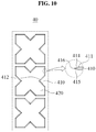
- FIG. 10 is a view illustrating another example of a screen and a portion of the screen with an enlarged cross section according to an example embodiment.
- a screen 40 may include a plate 410 and a through hole 420.
- a plurality of edges 411 that defines the through hole 420 may have a plurality of extension portions 414 and 415 formed on both sides based on a tip 416.
- the plurality of extension portions 414 and 415 may be formed on the plurality of edges 411 to be inclined at set angles with respect to the plate 410. In a preferred example, the angles at which the plurality of extension portions 414 and 415 are inclined relative to the plate 410 may be substantially the same.
- the plurality of extension portions 414 and 415 may be outwardly curved based on the plate 310.
- the plurality of extension portions 414 and 415 may be curved in different directions.
- curvature radiuses of the plurality of extension portions 414 and 415 may be substantially the same such that the tip 416 is located at a center between the plurality of extension portions 414 and 415.
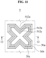
- FIG. 11 is a top view illustrating an example of a plurality of laminated screens according to an example embodiment
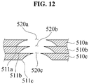
- FIG. 12 is a cross-sectional view taken along a line 12-12 of FIG. 11 .
- a device 5 for reducing a size of a biological tissue may include a plurality of screens 50a, 50b, and 50c laminated in sequence.
- the plurality of screens 50a, 50b, and 50c may respectively include plates 510a, 510b, and 510c and through holes 520a, 520b, and 520c defined by a plurality of edges 511a, a plurality of edges 511b, and a plurality of edges 511c.
- the plurality of screens 50a, 50b, and 50c may include protrusions 512a, 512b, and 512c protruding toward through holes 520a, 520b, and 520c.
- the plurality of edges 511a, 511b, and 511c may each have an extension portion and a tip.
- the through holes 520a, 520b, and 520c of the plurality of screens 50a, 50b, and 50c laminated in sequence may overlap one another in a direction in which sizes thereof decrease.
- a biological tissue passing through the plurality of screens 50a, 50b, and 50c may be gradually miniaturized while receiving a pressure applied due to a sharp cross section formed over the plurality of edges 511a, 511b, and 511c and/or shapes of the protrusions 512a, 512b, and 512c.
- FIG. 13 is a top view illustrating another example of a plurality of laminated screens according to an example embodiment
- FIG. 14 is a cross-sectional view taken along a line 14-14 of FIG. 13 .
- a device 6 for reducing a size of a biological tissue may include a plurality of screens 60a, 60b, and 60c laminated in sequence.
- the plurality of screens 60a, 60b, and 60c may respectively include plates 610a, 610b, and 610c and through holes 620a, 620b, and 620c defined by a plurality of edges 611a, a plurality of edges 611b, and a plurality of edges 611c.
- each of the plurality of edges 611a, 611b and may have a plurality of extension portions on both sides based on a tip.
- the through holes 620a, 620b, and 620c of the plurality of screens 60a, 60b, and 60c laminated in sequence may overlap one another in a direction in which sizes thereof decrease.
Landscapes
- Health & Medical Sciences (AREA)
- Heart & Thoracic Surgery (AREA)
- Life Sciences & Earth Sciences (AREA)
- Engineering & Computer Science (AREA)
- Biomedical Technology (AREA)
- General Health & Medical Sciences (AREA)
- Animal Behavior & Ethology (AREA)
- Hematology (AREA)
- Anesthesiology (AREA)
- Vascular Medicine (AREA)
- Public Health (AREA)
- Veterinary Medicine (AREA)
- Bioinformatics & Cheminformatics (AREA)
- Organic Chemistry (AREA)
- Wood Science & Technology (AREA)
- Zoology (AREA)
- Chemical & Material Sciences (AREA)
- Biotechnology (AREA)
- Genetics & Genomics (AREA)
- General Engineering & Computer Science (AREA)
- Biochemistry (AREA)
- Sustainable Development (AREA)
- Microbiology (AREA)
- Molecular Biology (AREA)
- Mechanical Engineering (AREA)
- Surgery (AREA)
- Apparatus Associated With Microorganisms And Enzymes (AREA)
- Surgical Instruments (AREA)
- Prostheses (AREA)
Abstract
Description
- One or more example embodiments relate to a device for reducing a size of biological tissue.
- Fat tissue, which is a kind of biological tissue, is obtained from a subject such as a person or an animal by suction or incision. Since the obtained fat tissue may be large in size and include a large amount of fibrous material, it is difficult to implant the fat tissue into the subject using a fine needle. Accordingly, a device for reducing a size of biological tissue such as the large fat tissue have been developed. For example,
U.S. Patent No. 6,139,757 discloses a method of separating cells from blood using a variable porosity filter. - An aspect provides a device for reducing a size of a biological tissue by scratching or tearing the biological tissue.
- Another aspect provides a device for gradually reducing a size of a biological tissue.
- According to an aspect, there is provided a device for reducing a size of a biological tissue, the device including a plate and a through hole defined by a plurality of edges of the plate and penetrating a front and a rear of the plate, wherein each of the plurality of edges includes a protrusion that protrudes toward a central portion of the through hole, and while a biological tissue passes through the through hole, the biological tissue is scratched and torn by the protrusion so that a size of the biological tissue is reduced.
- A width of the protrusion may decrease toward the central portion of the through hole such that a tip is formed.
- Each of the plurality of edges may include linear portions formed on both sides based on the protrusion. In other words, the protrusion may be formed in a central portion of the edge.
- The device may further include a first group of protrusions protruding in a first direction based on the plate while forming an angle with respect to the plate, and a second group of protrusions protruding in a second direction differing from the first direction based on the plate while forming an angle with respect to the plate. In other words, the first group of protrusions and the second group of protrusions may be provided in various ways. For example, the first group of protrusions may appear consecutively along a portion of the plurality of edges and the second group of protrusions may appear consecutively along a remaining portion of the plurality of edges.
- The first group of protrusions and the second group of protrusions may alternate in different directions along the plurality of edges.
- Extension lines of the first group of protrusions do not meet and are not parallel to extension lines of the second group of protrusions. In other words, an extension line of the first direction and an extension line of the second direction may be at skew positions.
- The device may further include an extension portion configured to extend from each of the plurality of edges toward the central portion of the through hole, and a tip formed at an end of the extension portion and configured to scratch and tear the biological tissue.
- The device may further include an additional extension portion formed on a side opposite to the extension portion based on the tip and configured to extend toward the central portion of the through hole.
- A protruding direction of the protrusion may not be parallel to a moving direction of the biological tissue passing through the through hole.
- According to another aspect, there is provided a device for reducing a size of a biological tissue, the device including: a first screen including a first plate, a first through hole defined by a plurality of first edges of the first plate and penetrating a front and a rear of the first plate, and a first protrusion that protrudes toward a central portion of the first through hole; and a second screen including a second plate laminated to the first plate, a second through hole defined by a plurality of second edges of the second plate and penetrating a front and a rear of the second plate, and a second protrusion that protrudes toward a central portion of the second through hole, wherein the first through hole overlaps the second through hole and is larger in size than the second through hole.
- Protruding directions of the first protrusion and the second protrusion may not be parallel to a moving direction of a biological tissue sequentially passing through the first through hole and the second through hole, and may be the same as or intersect with the moving direction.
- According to example embodiments, it is possible to provide a device for reducing a size of a biological tissue by scratching or tearing the biological tissue.
- According to example embodiments, it is possible to provide a device for gradually reducing a size of a biological tissue.
- The effects of obtainable from the present disclosure are non-limited by the above-mentioned effects. And, other unmentioned effects can be clearly understood from the following description by those having ordinary skill in the technical field to which the present disclosure pertains.
-
-
FIG. 1 is a perspective view illustrating a device for reducing a size of a biological tissue according to an example embodiment. -
FIG. 2 is an exploded side view illustrating a device for reducing a size of a biological tissue according to an example embodiment. -
FIG. 3 is a cross-sectional view illustrating a device for reducing a size of a biological tissue according to an example embodiment. -
FIG. 4 is a top view illustrating a screen according to an example embodiment. -
FIG. 5 is an enlarged view illustrating an example of a part A ofFIG. 4 . -
FIG. 6 is an enlarged view illustrating another example of the part A ofFIG. 4 . -
FIG. 7 is a side view illustrating a screen according to an example embodiment. -
FIG. 8 is an enlarged view illustrating an example of a part B ofFIG. 7 . -
FIG. 9 is a view illustrating an example of a screen and a portion of the screen with an enlarged cross section according to an example embodiment. -
FIG. 10 is a view illustrating another example of a screen and a portion of the screen with an enlarged cross section according to an example embodiment. -
FIG. 11 is a top view illustrating an example of a plurality of laminated screens according to an example embodiment. -
FIG. 12 is a cross-sectional view taken along a line 12-12 ofFIG. 11 . -
FIG. 13 is a top view illustrating another example of a plurality of laminated screens according to an example embodiment. -
FIG. 14 is a cross-sectional view taken along a line 14-14 ofFIG. 13 . - Hereinafter, example embodiments will be described in detail with reference to the accompanying drawings. It should be understood, however, that there is no intent to limit this disclosure to the particular example embodiments disclosed. On the contrary, example embodiments are to cover all modifications, equivalents, and alternatives falling within the scope of the example embodiments.
- Although terms such as "first," "second," "A", "B", "a", and "b" may be used herein to describe various members, components, regions, layers, or sections, these members, components, regions, layers, or sections are not to be limited by these terms. Throughout the specification, when an element, such as a layer, region, or substrate, is described as being "on," "connected to," or "coupled to" another element, it may be directly "on," "connected to," or "coupled to" the other element, or there may be one or more other elements intervening therebetween.
- Regarding the reference numerals assigned to the elements in the drawings, it should be noted that the same elements will be designated by the same reference numerals, wherever possible, even though they are shown in different drawings. Also, in the description of embodiments, detailed description of well-known related structures or functions will be omitted when it is deemed that such description will cause ambiguous interpretation of the present disclosure.
-
FIG. 1 is a perspective view illustrating a device for reducing a size of a biological tissue according to an example embodiment,FIG. 2 is an exploded side view illustrating a device for reducing a size of a biological tissue according to an example embodiment, andFIG. 3 is a cross-sectional view illustrating a device for reducing a size of a biological tissue according to an example embodiment. - Referring to
FIGS. 1 and2 , adevice 1 for reducing a size of a biological tissue may be configured to miniaturize a biological tissue and maximize a contact with a biological tissue to acquire a biological tissue in a desired size The biological tissue may include, for example, an adipose tissue. The biological tissue may be obtained from a living body of a subject such as a human being, an animal, or the like, by suction or incision. - The
device 1 may include ascreen 10, a sealingmember 12, afront cover 14, and arear cover 16. - The
screen 10 may be configured to reduce a size of a biological tissue. For example, thescreen 10 may have a disk shape. When a lump-shaped biological tissue passes through thescreen 10, thescreen 10 may scratch or tear the biological tissue. - The sealing
member 12 may cover an exterior of thescreen 10. The sealingmember 12 may form a seal between thescreen 10 and each of thefront cover 14 and therear cover 16. The sealingmember 12 may have a ring shape. For example, the sealingmember 12 may be formed with a rubber material. - The
front cover 14 and therear cover 16 may accept thescreen 10 and the sealingmember 12, respectively. Thefront cover 14 and therear cover 16 may be coupled to each other. For example, thefront cover 14 and therear cover 16 may be rotationally coupled. - The
front cover 14 and therear cover 16 may respectively include an inlet port and an outlet port through which the biological tissue flows. A passage connecting the inlet port and the outlet port may be between thefront cover 14 and therear cover 16. The biological tissue or a mass thereof may flow inside thefront cover 14 via the inlet port, pass thescreen 10 along the passage, and then flow from inside to outside therear cover 16 via the outlet port. -
FIG. 4 is a top view illustrating a screen according to an example embodiment. - Referring to
FIG. 4 , thescreen 10 may include aplate 110 and at least one throughhole 120. - The
plate 110 may have a disk shape. For example, theplate 110 may have a circular shape. Theplate 110 may be formed of a material suitable for preventing a contamination of a biological tissue. - The through
hole 120 may miniaturize the biological tissue and maximize a contact with the biological tissue. The throughhole 120 may penetrate a front and a rear of theplate 110 and be defined by a plurality of edges of theplate 110. The plurality of edges of theplate 110 that define the throughhole 120 may have irregular sizes. - The
plate 110 may be plate-molded overall so that a position at which the throughhole 120 is formed in theplate 110 is not changed or a shape of the throughhole 120 is not deformed by an external force. -
FIG. 5 is an enlarged view illustrating an example of a part A ofFIG. 4 . - Referring to
FIG. 5 , a plurality ofedges 111 that define the throughhole 120 may define the throughhole 120 such that the throughhole 120 substantially has a quadrangular shape. - Each of the plurality of
edges 111 may include aprotrusion 112. Theprotrusion 112 may protrude toward a central portion of the throughhole 120. While a biological tissue passes through the throughhole 120, theprotrusion 112 may scratch or tear the biological tissue. Among constituent components of the biological tissue, a fiber which is greater in size than the throughhole 120 may not pass through the throughhole 120. - A protruding direction of the
protrusion 112 may not be parallel to a moving direction of the biological tissue passing through the throughhole 120. For example, the protruding direction of theprotrusion 112 may be parallel to a tangential direction of theplate 110 or may be at a set angle with respect to the tangential direction of theplate 110. Here, an angle between theprotrusion 112 and theplate 110 may be set as an acute angle, an obtuse angle, or a reflex angle. - A width of the
protrusion 112 may decrease toward the central portion of the throughhole 120, so that atip 1121 is formed. For example, theprotrusion 112 may have a triangular shape. - The plurality of
edges 111 may includelinear portions protrusion 112. In other words, theprotrusion 112 may be located in a central portion of theedge 111. For example, thelinear portions protrusion 112 is at a center of theedge 111. In this example, theprotrusion 112 of theedge 111 and a protrusion of an edge facing theedge 111 may face each other toward the central portion of the throughhole 120. Although not shown, thelinear portions linear portions protrusion 112. - As such, due to an irregular shape of the through
hole 120 defined by the plurality ofedges 111, sharp cross-sections of the plurality ofedges 111, and the like, a pressure may be applied to the biological tissue passing through the throughhole 120 so that the lump-shaped biological tissue may be torn or scratched. -
FIG. 6 is an enlarged view illustrating another example of the part A ofFIG. 4 . - Referring to
FIG. 6 , a plurality of edges 111' that define the throughhole 120 may define the throughhole 120 such that the throughhole 120 substantially has a polygonal shape having at least four corners. The plurality of edges 111' may include a protrusion 112' that protrudes toward the central portion of the throughhole 120. A width of the protrusion 112' may decrease toward the central portion of the throughhole 120 so that atip 1121 is formed. - In the example embodiment, the plurality of edges 111' may not have linear portions formed on both sides based on the protrusion 112' or may have linear portions with lengths relatively small when compared to a size of the protrusion 112'. In other words, a plurality of protrusions 112' may be adjacent to one another along the plurality of edges 111'.
-
FIG. 7 is a side view illustrating a screen according to an example embodiment, andFIG. 8 is an enlarged view illustrating an example of a part B ofFIG. 7 . - Referring to
FIGS. 7 and8 , ascreen 20 may include aplate 210 and a throughhole 220. In the example embodiment,protrusions edges plate 210 may be at a set angle with respect to a tangential direction of theplate 210. A moving direction of a lump-shaped biological tissue BM passing through the throughhole 220 from a front of thescreen 20 to a rear of thescreen 20 may nor parallel to protruding directions of theprotrusions protrusions - The plurality of
edges protrusions plate 210. In other words, the plurality of protrusions 212a, 212b may be classified into a plurality of groups. For example, the plurality of protrusions 212a, 212b may be classified into a first group of protrusions that protrude in a first direction based on theplate 210 while forming an angle with respect to theplate 210 and a second group of protrusions that protrude in a second direction based on theplate 210 while forming an angle with respect to theplate 210. - Here, the first direction may be different from the second direction. The first direction differing from the second direction may indicate that the first direction is not parallel to the second direction. For example, referring to
FIG. 8 , theprotrusion 212a of the first direction may protrude to a left side of theplate 210 and theprotrusion 212b of the second direction may protrude to a right side of theplate 210. - In one example, the
protrusion 212 a of the first group and theprotrusion 212b of the second group may be adjacent to each other. In a preferred example, theprotrusion 212a of the first group and theprotrusion 212b of the second group may be alternated with each other. - Although not shown, the plurality of
protrusions 212a in the first group and the plurality ofprotrusions 212b in the second group may be grouped and adjacent in each of the groups. In this case, the plurality ofprotrusions 212a in the first group may be sequentially formed on a portion of the plurality ofedges protrusions 212b in the second group may be sequentially formed on a remaining portion of the plurality ofedges - As such, the plurality of
protrusions 212a in the first group and the plurality ofprotrusions 212b in the second group may be arranged in various ways. - In an example embodiment, an extension line of the
protrusion 212a in the first group may not meet and not be parallel to an extension line of theprotrusion 212b in the second group. In other words, the extension line of theprotrusion 212a in the first group and the extension line of theprotrusion 212b in the second group may be at skew positions in a three-dimensional (3D) space. For example, a vertex at which theedge 211a including theprotrusion 212a of the first group meets theedge 211b including theprotrusion 212b of the second group may be set to be an origin. In addition, the first direction in which theprotrusion 212a of the first group protrudes may be set to be an x axis, the second direction in which theprotrusion 212b of the second group protrudes may be set to be an y axis, and an outer product of the first direction and the second direction may be set to be a z axis. In this example, a vector from theedge 212a including theprotrusion 212a of the first group to a tip of theedge 212a may be (1, 0, - 1), and a vector from theedge 212b including theprotrusion 212b of the second group to a tip of theedge 212b may be (-1, 0, 1). -
FIG. 9 is a view illustrating an example of a screen and a portion of the screen with an enlarged cross section according to an example embodiment. - Referring to
FIG. 9 , ascreen 30 may include aplate 310 and a throughhole 320. In the example embodiment, a sharp cross section may be formed over a plurality ofedges 311 of theplate 310 that define the throughhole 320. For example, thescreen 30 may include an extension portion that extends from each of the plurality of edges toward a central portion of the throughhole 320 and atip 316 formed at an end of theextension portion 314 to scratch and tear a biological tissue. - The
extension portion 314 may have any suitable shape. In one example, theextension portion 314 may be formed to be inclined based on a plane of theplate 310. In another example, theextension portion 314 may be outwardly curved based on theplate 310. -
FIG. 10 is a view illustrating another example of a screen and a portion of the screen with an enlarged cross section according to an example embodiment. - Referring to
FIG. 10 , ascreen 40 may include aplate 410 and a throughhole 420. In this example embodiment, a plurality ofedges 411 that defines the throughhole 420 may have a plurality ofextension portions tip 416. In one example, the plurality ofextension portions edges 411 to be inclined at set angles with respect to theplate 410. In a preferred example, the angles at which the plurality ofextension portions plate 410 may be substantially the same. - In an additional example embodiment, the plurality of
extension portions plate 310. In this case, the plurality ofextension portions extension portions tip 416 is located at a center between the plurality ofextension portions -
FIG. 11 is a top view illustrating an example of a plurality of laminated screens according to an example embodiment, andFIG. 12 is a cross-sectional view taken along a line 12-12 ofFIG. 11 . - Referring to
FIGS. 11 and12 , a device 5 for reducing a size of a biological tissue may include a plurality ofscreens screens plates holes edges 511a, a plurality ofedges 511b, and a plurality ofedges 511c. The plurality ofscreens protrusions holes FIG. 9 , the plurality ofedges - In the example embodiment, the through
holes screens FIG. 12 ) may overlap one another in a direction in which sizes thereof decrease. Through this, a biological tissue passing through the plurality ofscreens edges protrusions -
FIG. 13 is a top view illustrating another example of a plurality of laminated screens according to an example embodiment, andFIG. 14 is a cross-sectional view taken along a line 14-14 ofFIG. 13 . - Referring to
FIGS. 13 and14 , adevice 6 for reducing a size of a biological tissue may include a plurality ofscreens screens plates holes edges 611a, a plurality ofedges 611b, and a plurality ofedges 611c. As described with reference toFIG. 10 , each of the plurality ofedges - In the example embodiment, the through
holes screens FIG. 14 ) may overlap one another in a direction in which sizes thereof decrease. - Although a few embodiments of the present invention have been shown and described, the present invention is not limited to the described embodiments. Instead, it would be appreciated by those skilled in the art that changes may be made to these embodiments without departing from the principles and spirit of the invention, the scope of which is defined by the claims and their equivalents.
Claims (11)
- A device for reducing a size of a biological tissue, the device comprising:a plate; anda through hole defined by a plurality of edges of the plate and penetrating a front and a rear of the plate,wherein each of the plurality of edges comprises a protrusion that protrudes toward a central portion of the through hole, andwhile a biological tissue passes through the through hole, the biological tissue is scratched and torn by the protrusion so that a size of the biological tissue is reduced.
- The device of claim 1, wherein a width of the protrusion decreases toward the central portion of the through hole such that a tip is formed.
- The device of claim 1, wherein each of the plurality of edges comprises linear portions formed on both sides based on the protrusion.
- The device of claim 1, further comprising:a first group of protrusions protruding in a first direction based on the plate while forming an angle with respect to the plate; anda second group of protrusions protruding in a second direction differing from the first direction based on the plate while forming an angle with respect to the plate.
- The device of claim 4, wherein the first group of protrusions and the second group of protrusions alternate in different directions along the plurality of edges.
- The device of claim 4, wherein extension lines of the first group of protrusions do not meet and are not parallel to extension lines of the second group of protrusions.
- The device of claim 1, further comprising:an extension portion configured to extend from each of the plurality of edges toward the central portion of the through hole; anda tip formed at an end of the extension portion and configured to scratch and tear the biological tissue.
- The device of claim 7, further comprising:
an additional extension portion formed on a side opposite to the extension portion based on the tip and configured to extend toward the central portion of the through hole. - The device of claim 1, wherein a protruding direction of the protrusion is not parallel to a moving direction of the biological tissue passing through the through hole.
- A device for reducing a size of a biological tissue, the device comprising:a first screen comprising a first plate, a first through hole defined by a plurality of first edges of the first plate and penetrating a front and a rear of the first plate, and a first protrusion that protrudes toward a central portion of the first through hole; anda second screen comprising a second plate laminated to the first plate, a second through hole defined by a plurality of second edges of the second plate and penetrating a front and a rear of the second plate, and a second protrusion that protrudes toward a central portion of the second through hole,wherein the first through hole overlaps the second through hole and is larger in size than the second through hole.
- The device of claim 10, wherein protruding directions of the first protrusion and the second protrusion are not parallel to a moving direction of a biological tissue sequentially passing through the first through hole and the second through hole, and are the same as or intersect with the moving direction.
Applications Claiming Priority (3)
| Application Number | Priority Date | Filing Date | Title |
|---|---|---|---|
| KR20170113331 | 2017-09-05 | ||
| KR1020180101991A KR102051223B1 (en) | 2017-09-05 | 2018-08-29 | Device for size reduction of biological tissue |
| PCT/KR2018/010278 WO2019050251A1 (en) | 2017-09-05 | 2018-09-04 | Device for reducing size of biological tissue |
Publications (2)
| Publication Number | Publication Date |
|---|---|
| EP3679961A1 true EP3679961A1 (en) | 2020-07-15 |
| EP3679961A4 EP3679961A4 (en) | 2021-06-09 |
Family
ID=65762261
Family Applications (1)
| Application Number | Title | Priority Date | Filing Date |
|---|---|---|---|
| EP18854041.3A Pending EP3679961A4 (en) | 2017-09-05 | 2018-09-04 | Device for reducing size of biological tissue |
Country Status (5)
| Country | Link |
|---|---|
| US (1) | US11987786B2 (en) |
| EP (1) | EP3679961A4 (en) |
| JP (1) | JP6898686B2 (en) |
| KR (1) | KR102051223B1 (en) |
| CN (1) | CN111032107B (en) |
Families Citing this family (6)
| Publication number | Priority date | Publication date | Assignee | Title |
|---|---|---|---|---|
| EP3826651A4 (en) * | 2018-07-24 | 2022-05-11 | Healeon LLC | DEVICE AND METHOD FOR RESIZING FAT TISSUE AND OTHER TISSUES FOR IMPLANTATION |
| KR102202861B1 (en) * | 2019-04-09 | 2021-01-18 | 이준석 | Apparatus for changing screen, system for reducing size of biological tissue comprising the same, method of using the same and method of separating target material from biological tissue associated therewith |
| WO2020209609A2 (en) * | 2019-04-09 | 2020-10-15 | 이준석 | Screen exchange device, biological tissue size reduction system comprising same, biological tissue size reduction method using same, and method for separating target substance from relevant biological tissue |
| CN110560232B (en) * | 2019-09-30 | 2024-04-30 | 长沙赋妍医疗科技有限公司 | External fine particle fat preparation all-in-one |
| CN115335509A (en) * | 2020-03-27 | 2022-11-11 | 李晙硕 | Method for mechanically separating tissue and cells constituting living tissue |
| CN113426562A (en) * | 2021-07-29 | 2021-09-24 | 厦门博森再生医学工程有限公司 | Cutting filter screen and breaker |
Family Cites Families (23)
| Publication number | Priority date | Publication date | Assignee | Title |
|---|---|---|---|---|
| GB863487A (en) * | 1957-05-22 | 1961-03-22 | Hans Strasser | Mincing, emulsifying and homogenizing machine, in particular for meat |
| US3836464A (en) | 1972-07-14 | 1974-09-17 | Brown Int Corp | Filter screen mounting |
| US3941317A (en) * | 1973-10-26 | 1976-03-02 | Lnih, Inc. | Method and apparatus for tissue disaggregation |
| US5172920A (en) * | 1992-01-28 | 1992-12-22 | Diamond Manufacturing Co. | Composite material for gaskets |
| US5626751A (en) | 1992-07-15 | 1997-05-06 | Daiichi Pharmaceutical Co., Ltd. | Filter unit and high-pressure sizing apparatus |
| DE69413557T2 (en) | 1993-12-21 | 1999-06-17 | Genera Technologies Ltd., Cambridge | METHOD AND DEVICE FOR FILTRATION |
| JP3322595B2 (en) * | 1996-03-28 | 2002-09-09 | テルモ株式会社 | Filter device and method for separating / collecting biological microstructure |
| WO2002088296A1 (en) * | 2001-04-26 | 2002-11-07 | Boston Biomedica, Inc. | Multichamber device and uses thereof for processing of biological samples |
| TWI255738B (en) * | 2003-12-31 | 2006-06-01 | Ind Tech Res Inst | Tissue pulverizer |
| TWM252372U (en) * | 2004-03-30 | 2004-12-11 | Chung-Jen Pai | Improved filing sheet |
| JP2006082816A (en) * | 2004-09-14 | 2006-03-30 | Dainippon Printing Co Ltd | Method for producing gas barrier plastic container |
| US20060142773A1 (en) * | 2004-12-29 | 2006-06-29 | Depuy Mitek, Inc. | Abrasive cutting system and method |
| KR100748487B1 (en) * | 2006-05-16 | 2007-08-10 | 장동 | Tissue volume reduction device using high frequency energy |
| US20070287933A1 (en) * | 2006-06-08 | 2007-12-13 | Chris Phan | Tissue debulking device and method of using the same |
| WO2010036788A2 (en) * | 2008-09-24 | 2010-04-01 | The General Hospital Corporation | Method and apparatus for grafting of skin tissue |
| US9192939B2 (en) | 2010-03-23 | 2015-11-24 | Lipogems International S.P.A. | Device and a method for preparing a tissue |
| IT1400069B1 (en) | 2010-05-20 | 2013-05-17 | Tremolada | DEVICE AND METHOD FOR THE PREPARATION OF FABRIC, IN PARTICULAR ADIPOUS FABRIC FOR TRANSPLANTATION OBTAINED FROM ADIPOUS LOBULAR MATERIAL EXTRACTED THROUGH LIPOSUCTION |
| US9427512B2 (en) | 2012-06-08 | 2016-08-30 | Pall Corporation | Filter device |
| WO2015030228A1 (en) | 2013-09-02 | 2015-03-05 | 株式会社ラステック | Porous plate for medical use and production method for porous plate for medical use |
| ES2978108T3 (en) * | 2014-09-04 | 2024-09-05 | Becton Dickinson Co | Devices and methods for dissociating a sample of biological tissue |
| KR101605849B1 (en) | 2014-11-28 | 2016-03-23 | 이준석 | Fat transplantation container |
| EA035048B1 (en) * | 2014-12-15 | 2020-04-22 | Хьюман Брэйн Уэйв С.Р.Л. | Disgregating device of biological material and corresponding manufacturing method and method for the preparation of cell suspensions and tissue micrografts |
| US10927347B2 (en) * | 2015-05-15 | 2021-02-23 | Black Tie Medical Inc. | Device and method for breaking down and sizing harvested fat |
-
2018
- 2018-08-29 KR KR1020180101991A patent/KR102051223B1/en active Active
- 2018-09-04 JP JP2020531411A patent/JP6898686B2/en active Active
- 2018-09-04 CN CN201880052037.5A patent/CN111032107B/en active Active
- 2018-09-04 US US16/635,621 patent/US11987786B2/en active Active
- 2018-09-04 EP EP18854041.3A patent/EP3679961A4/en active Pending
Also Published As
| Publication number | Publication date |
|---|---|
| EP3679961A4 (en) | 2021-06-09 |
| KR102051223B1 (en) | 2019-12-03 |
| US20200237995A1 (en) | 2020-07-30 |
| KR20190026586A (en) | 2019-03-13 |
| JP6898686B2 (en) | 2021-07-07 |
| CN111032107B (en) | 2023-10-03 |
| CN111032107A (en) | 2020-04-17 |
| JP2020531218A (en) | 2020-11-05 |
| US11987786B2 (en) | 2024-05-21 |
Similar Documents
| Publication | Publication Date | Title |
|---|---|---|
| EP3679961A1 (en) | Device for reducing size of biological tissue | |
| JP6942768B2 (en) | Wound bandage | |
| CN105792637B (en) | Emitter and drip irrigation pipe | |
| US11273249B2 (en) | Fluid volume measurement using canister resonance for reduced pressure therapy systems | |
| US9925317B2 (en) | Low-profile reduced pressure treatment system | |
| AU2007335240B2 (en) | Needle tip | |
| AU2009234016A1 (en) | Mask nose clip and a respiratory mask | |
| JP2020523078A (en) | Composite dressing for promoting granulation and reducing maceration by negative pressure treatment | |
| EP3092892A1 (en) | Emitter and drip irrigation tube | |
| EP3124060B1 (en) | Silencer for a vacuum therapy unit | |
| EP3865111A1 (en) | Facial mask sheet, facial mask assembly, and method for manufacturing same | |
| US20220258163A1 (en) | Microfluidic particle sorting apparatus and manufacturing method thereof | |
| JP4161026B2 (en) | Medical knife | |
| JP6875788B2 (en) | Blood circuit with pressure measuring unit | |
| WO2019050251A1 (en) | Device for reducing size of biological tissue | |
| JP2005013517A (en) | Grater | |
| US11161067B2 (en) | Filtration system and method of use | |
| KR101276187B1 (en) | Cells collection apparatus | |
| EP1939136A3 (en) | High throughput pressure resistant microfluidic devices | |
| EP2815775B1 (en) | Biological fluid filters with port for optimized flow distribution | |
| CN209921995U (en) | A biaxially stretchable pearl cotton and a die-cutting die for preparing the pearl cotton | |
| CN215087254U (en) | Hollow side-opening pasteur straw | |
| USD890949S1 (en) | Sample port for blood collection device | |
| CN208628088U (en) | An infusion bag destroyer | |
| JP4853715B2 (en) | Blood filter device |
Legal Events
| Date | Code | Title | Description |
|---|---|---|---|
| STAA | Information on the status of an ep patent application or granted ep patent |
Free format text: STATUS: THE INTERNATIONAL PUBLICATION HAS BEEN MADE |
|
| PUAI | Public reference made under article 153(3) epc to a published international application that has entered the european phase |
Free format text: ORIGINAL CODE: 0009012 |
|
| STAA | Information on the status of an ep patent application or granted ep patent |
Free format text: STATUS: REQUEST FOR EXAMINATION WAS MADE |
|
| 17P | Request for examination filed |
Effective date: 20200129 |
|
| AK | Designated contracting states |
Kind code of ref document: A1 Designated state(s): AL AT BE BG CH CY CZ DE DK EE ES FI FR GB GR HR HU IE IS IT LI LT LU LV MC MK MT NL NO PL PT RO RS SE SI SK SM TR |
|
| AX | Request for extension of the european patent |
Extension state: BA ME |
|
| DAV | Request for validation of the european patent (deleted) | ||
| DAX | Request for extension of the european patent (deleted) | ||
| A4 | Supplementary search report drawn up and despatched |
Effective date: 20210510 |
|
| RIC1 | Information provided on ipc code assigned before grant |
Ipc: A61M 1/02 20060101AFI20210503BHEP Ipc: A61M 1/00 20060101ALI20210503BHEP Ipc: B02C 18/36 20060101ALI20210503BHEP Ipc: G01N 1/28 20060101ALI20210503BHEP |
|
| STAA | Information on the status of an ep patent application or granted ep patent |
Free format text: STATUS: EXAMINATION IS IN PROGRESS |
|
| 17Q | First examination report despatched |
Effective date: 20250829 |