EP3680433A1 - Gabarit de forage et utilisation d'un gabarit de forage - Google Patents
Gabarit de forage et utilisation d'un gabarit de forage Download PDFInfo
- Publication number
- EP3680433A1 EP3680433A1 EP19151671.5A EP19151671A EP3680433A1 EP 3680433 A1 EP3680433 A1 EP 3680433A1 EP 19151671 A EP19151671 A EP 19151671A EP 3680433 A1 EP3680433 A1 EP 3680433A1
- Authority
- EP
- European Patent Office
- Prior art keywords
- plate
- fixing holes
- drilling template
- positioning pins
- holes
- Prior art date
- Legal status (The legal status is an assumption and is not a legal conclusion. Google has not performed a legal analysis and makes no representation as to the accuracy of the status listed.)
- Withdrawn
Links
Images


Classifications
-
- E—FIXED CONSTRUCTIONS
- E05—LOCKS; KEYS; WINDOW OR DOOR FITTINGS; SAFES
- E05D—HINGES OR SUSPENSION DEVICES FOR DOORS, WINDOWS OR WINGS
- E05D11/00—Additional features or accessories of hinges
- E05D11/0009—Templates for marking the position of fittings on wings or frames
-
- E—FIXED CONSTRUCTIONS
- E05—LOCKS; KEYS; WINDOW OR DOOR FITTINGS; SAFES
- E05Y—INDEXING SCHEME ASSOCIATED WITH SUBCLASSES E05D AND E05F, RELATING TO CONSTRUCTION ELEMENTS, ELECTRIC CONTROL, POWER SUPPLY, POWER SIGNAL OR TRANSMISSION, USER INTERFACES, MOUNTING OR COUPLING, DETAILS, ACCESSORIES, AUXILIARY OPERATIONS NOT OTHERWISE PROVIDED FOR, APPLICATION THEREOF
- E05Y2800/00—Details, accessories and auxiliary operations not otherwise provided for
- E05Y2800/20—Combinations of elements
- E05Y2800/205—Combinations of elements forming a unit
-
- E—FIXED CONSTRUCTIONS
- E05—LOCKS; KEYS; WINDOW OR DOOR FITTINGS; SAFES
- E05Y—INDEXING SCHEME ASSOCIATED WITH SUBCLASSES E05D AND E05F, RELATING TO CONSTRUCTION ELEMENTS, ELECTRIC CONTROL, POWER SUPPLY, POWER SIGNAL OR TRANSMISSION, USER INTERFACES, MOUNTING OR COUPLING, DETAILS, ACCESSORIES, AUXILIARY OPERATIONS NOT OTHERWISE PROVIDED FOR, APPLICATION THEREOF
- E05Y2800/00—Details, accessories and auxiliary operations not otherwise provided for
- E05Y2800/45—Manufacturing
- E05Y2800/46—Injection moulding
-
- E—FIXED CONSTRUCTIONS
- E05—LOCKS; KEYS; WINDOW OR DOOR FITTINGS; SAFES
- E05Y—INDEXING SCHEME ASSOCIATED WITH SUBCLASSES E05D AND E05F, RELATING TO CONSTRUCTION ELEMENTS, ELECTRIC CONTROL, POWER SUPPLY, POWER SIGNAL OR TRANSMISSION, USER INTERFACES, MOUNTING OR COUPLING, DETAILS, ACCESSORIES, AUXILIARY OPERATIONS NOT OTHERWISE PROVIDED FOR, APPLICATION THEREOF
- E05Y2800/00—Details, accessories and auxiliary operations not otherwise provided for
- E05Y2800/67—Materials; Strength alteration thereof
- E05Y2800/676—Plastics
-
- E—FIXED CONSTRUCTIONS
- E05—LOCKS; KEYS; WINDOW OR DOOR FITTINGS; SAFES
- E05Y—INDEXING SCHEME ASSOCIATED WITH SUBCLASSES E05D AND E05F, RELATING TO CONSTRUCTION ELEMENTS, ELECTRIC CONTROL, POWER SUPPLY, POWER SIGNAL OR TRANSMISSION, USER INTERFACES, MOUNTING OR COUPLING, DETAILS, ACCESSORIES, AUXILIARY OPERATIONS NOT OTHERWISE PROVIDED FOR, APPLICATION THEREOF
- E05Y2800/00—Details, accessories and auxiliary operations not otherwise provided for
- E05Y2800/69—Permanence of use
- E05Y2800/692—Temporary use, e.g. removable tools
-
- E—FIXED CONSTRUCTIONS
- E05—LOCKS; KEYS; WINDOW OR DOOR FITTINGS; SAFES
- E05Y—INDEXING SCHEME ASSOCIATED WITH SUBCLASSES E05D AND E05F, RELATING TO CONSTRUCTION ELEMENTS, ELECTRIC CONTROL, POWER SUPPLY, POWER SIGNAL OR TRANSMISSION, USER INTERFACES, MOUNTING OR COUPLING, DETAILS, ACCESSORIES, AUXILIARY OPERATIONS NOT OTHERWISE PROVIDED FOR, APPLICATION THEREOF
- E05Y2900/00—Application of doors, windows, wings or fittings thereof
- E05Y2900/20—Application of doors, windows, wings or fittings thereof for furniture, e.g. cabinets
Definitions
- the invention relates to a drilling template and the use of such a drilling template for producing fastening holes in a front and / or a side wall of a cabinet.
- a front for example in the form of a flap
- a piece of furniture by means of furniture fittings.
- fittings such as cover plates are used, which have a base plate and an adjusting arm.
- the base plate is attached to a side wall of the furniture body.
- the adjusting arm which is pivotally attached to the base plate, is pivotally connected to the flap by means of a mounting bracket.
- Fastening holes must be drilled in the flap to attach the fastening fitting to the flap.
- mounting holes must be drilled in the side wall to attach the base plate to the side wall.
- the object of the present invention is to provide an aid in order to be able to easily make fastening bores in the front and / or in the side wall of the furniture body at the correct positions.
- the task is solved by a drilling template, which a plate to put on has a surface of a front and / or a side wall of a cabinet.
- the drilling template has different groups of fixing holes that penetrate the plate.
- the drilling template comprises positioning pins which can be inserted into the fixing holes of any group of fixing holes, and in the inserted state they protrude on both sides of the plate.
- the drilling template has guide holes which penetrate the plate and are used to guide a drill.
- the positioning pins are inserted into this selected group of fixing holes, with these protruding on both sides of the plate.
- the plate can be placed on a side surface of the front of the cabinet, with some of the positioning pins against a first narrow side and another part of the positioning pins against a second narrow side of the front of the cabinet. In this position of the plate, the guide holes are in the correct position for the respective front. Because the positioning pins protrude on both sides of the plate, the drilling template can be placed on both sides of the surface of the front, so that the drilling template can be used for both the left side and the right side of the front.
- the positioning pins can be removed from the plate, in particular can be broken out, in the delivery state of the drilling template.
- the positioning pins can be arranged in openings in the plate, the positioning pins being integrally connected to the plate via a plurality of webs.
- the drilling template with the plate and the positioning pins can be injection molded as an integral component made of plastic.
- the positioning pins can each have a central seat section which sits in the fixing hole of the plate when the positioning pin is inserted.
- Positioning sections are arranged on both sides of the seat section, the seat section compared to the positioning sections is enlarged in diameter. Accordingly, it can be provided that the seat section sits with a press fit in the respective fixing hole and simple insertion of the positioning pins into the fixing holes is achieved in that the positioning sections are reduced in diameter compared to the seat section.
- the groups of fixing holes can each comprise at least three fixing holes, a first fixing hole and a second fixing hole of the at least three fixing holes of a group each being arranged on a first straight line and the first straight lines of the individual groups of fixing holes being arranged parallel and spaced apart from one another.
- a third fixing hole of the at least three fixing holes of a group can be arranged on a second straight line, the second straight line being arranged at right angles to the first straight line of the respective group of fixing holes.
- the second straight lines of the individual groups of fixing holes are arranged parallel and spaced apart.
- the positioning pins can be inserted into a predetermined group of the various groups of fixing holes.
- the plate can be placed on a surface of the side wall of the cabinet, the positioning pins each abutting against a narrow side of the side wall of the cabinet and the plate being flush with an upper edge of the side wall.
- the fastening holes are then drilled in the side wall through the guide holes. This means that the drilling template can be used for the front of a cabinet as well as for the body or the side wall of the cabinet.
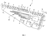
- FIG. 1 shows a perspective view of a drilling template 1.
- the drilling template 1 comprises a plate 2 for laying on a surface of a front and / or a side wall of a cabinet.
- a large number of fixing holes 3, 3 ', 3 ", 4, 4', 12, 12 ', 12" are arranged in the plate 2 and penetrate the plate 2.
- the fixing holes 3, 3 ', 3 ", 4, 4', 12, 12 ', 12" are arranged in several groups F1 to F12, K.
- the drilling template 1 further comprises three positioning pins 5, 5 ', 5 ", which can be inserted into the fixing holes 3, 3', 3", 4, 4 ', 12, 12', 12 "of any group of groups F1 to F12, K. are.
- the positioning pins 5, 5 ', 5" are arranged in the openings 7, 7' in this way that they can be removed from plate 2.
- the plate 2 and the positioning pins 5, 5 ', 5" are integral Injection molded plastic component.
- the positioning pins 5, 5', 5" can be inserted into any fixing hole 3, 3 ', 3 ", 4, 4 ', 12, 12', 12 “are inserted, the seat section 9 being arranged in the respective fixing hole 3, 3 ', 3", 4, 4', 12, 12 ', 12 "in the fully inserted state and with Press fit is held.
- the diameter of the seat section 9 is enlarged compared to the diameters of the positioning sections 10, 11.
- a table 13 is located on a surface of the drilling template 1.
- Table 13 can be used to determine, using size parameters of the cabinet, in which group F1 to F12, K of fixing holes the positioning pins 5, 5 ', 5 "are used to correctly position the guide holes 6, 6 ', 6 "and to be able to drill fixing holes through the guide holes 6, 6', 6" at a suitable point on the front of the cabinet.
- the size parameters of the cabinet are the wall thickness W of the side wall of the cabinet and the gap dimension G of an outer edge of the front to an outer surface of the side wall.
- the wall thickness W specifies which row of values for the gap dimension G must be used. If the wall thickness W is 18 mm, for example, and the gap dimension G 0 mm, the positioning pins 5, 5 ', 5 "are to be inserted into the fixing holes 3, 3', 3" of the twelfth group F12 of fixing holes.
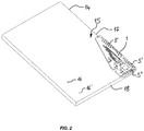
- the positioning pins 5, 5 ', 5 are then pressed out of the openings 7, 7' and inserted into the fixing holes 3, 3 ', 3" of the twelfth group F12 of fixing holes, as shown in FIGS Figures 2 to 4 is shown.
- the positioning pins 5, 5 ', 5 “here protrude on both sides of the plate 2, as can be seen in particular from the Figures 3 and 4 can be seen.
- the groups F1 to F12 each comprise three fixing holes 3, 3 ', 3 ", 12, 12', 12". There are also three positioning pins 5, 5 ', 5 ".
- a first fixing hole 5 and a second fixing hole 5' of the twelfth group F12 are arranged on a first straight line X 12.
- a third fixing hole 5" of the twelfth group F12 is on a second straight line Y 12 is arranged, the second straight line Y12 being arranged at a right angle to the first straight line X12.
- the fixing holes of the other groups of fixing holes are arranged in the same way to each other.
- the fixing holes of the different groups are arranged on the plate 2 such that the first straight lines of the individual groups of fixing holes are arranged parallel and at a distance from one another. Furthermore, the second straight lines of the individual groups of fixing holes are also arranged parallel and at a distance from one another.
- FIG. 1 An example is in Figure 1 In addition to the first straight line X 12 of the twelfth group F12 of fixing holes, the first straight line X 1 of the first group F1 of fixing holes is also shown, it being evident that these are parallel and objectionable to one another. Furthermore, the second straight line Y 12 of the twelfth group F12 and the second straight line Y 1 of the first group F1 are shown, which are likewise arranged parallel and at a distance from one another.
- the Figures 2 to 4 show a front 14 of a cabinet, wherein the drilling template 1 is placed on a surface 15 of the front 14.
- the drilling template 1 can be placed on the front 14 such that the positioning pins 5, 5 'rest in the first fixing hole 3 and in the second fixing hole 3' on a first narrow side 17 of the front 14.
- the positioning pin 5 "in the third fixing hole 3" rests on a second narrow side 18 of the front 14, the first narrow side 17 and the second narrow side 18 running at a right angle to one another.
- the guide holes 6, 6 ', 6 are in a correct position for the given size parameters of the cabinet, so that mounting holes 16, 16' are drilled into the front 14 with a drill through the guide holes 6, 6" can.
- the drilling template 1 can be turned over and with its side according to Figure 2 does not lie directly on the surface 15 of the front 14, be placed on the surface 15 in order to also be able to introduce fastening bores 16, 16 ′ on a side of the front 14 facing away from the first narrow side 17.
- the guide holes of the different groups F1 to F12 are arranged at different distances from the guide holes 6, 6 ', 6 ", the guide holes are positioned differently depending on the selection of the group F1 to F12 of fixing holes and adapted to the size parameters of the respective cabinet .
- the drilling template 1 is placed on a surface 20 of the side wall 19, as shown in FIGS Figures 5 and 6 is shown.
- the third positioning pin 5 "of the three positioning pins 5, 5 ', 5" is not used.
- the drilling template 1 is then placed against the side wall 19 in such a way that the positioning pins 5, 5 ′ bear against a narrow side 21 of the side wall 19.
- the drilling template 1 is held in contact with an upper floor 22 of the cabinet in order to bring the guide holes 6, 6 ', 6 "into the correct position. In this position, the plate 2 is flush with an upper edge 23 of the side wall 19. Then through the guide holes 6, 6 ', 6 "mounting holes are drilled in the side wall 19.
- the drilling template 1 can be turned over and with its side according to Figure 5 does not lie directly on the surface 20 of the side wall 19, be placed on the surface of an opposite side wall (not shown) in order to be able to drill fastening holes in the opposite side wall.
- the narrow sides 17, 18, 21 are those sides which run at right angles to the surfaces 15, 20 on which the drilling template is placed and which extend in the thickness direction of the front or the side wall.
Landscapes
- Engineering & Computer Science (AREA)
- Mechanical Engineering (AREA)
- Perforating, Stamping-Out Or Severing By Means Other Than Cutting (AREA)
Priority Applications (1)
| Application Number | Priority Date | Filing Date | Title |
|---|---|---|---|
| EP19151671.5A EP3680433A1 (fr) | 2019-01-14 | 2019-01-14 | Gabarit de forage et utilisation d'un gabarit de forage |
Applications Claiming Priority (1)
| Application Number | Priority Date | Filing Date | Title |
|---|---|---|---|
| EP19151671.5A EP3680433A1 (fr) | 2019-01-14 | 2019-01-14 | Gabarit de forage et utilisation d'un gabarit de forage |
Publications (1)
| Publication Number | Publication Date |
|---|---|
| EP3680433A1 true EP3680433A1 (fr) | 2020-07-15 |
Family
ID=65023808
Family Applications (1)
| Application Number | Title | Priority Date | Filing Date |
|---|---|---|---|
| EP19151671.5A Withdrawn EP3680433A1 (fr) | 2019-01-14 | 2019-01-14 | Gabarit de forage et utilisation d'un gabarit de forage |
Country Status (1)
| Country | Link |
|---|---|
| EP (1) | EP3680433A1 (fr) |
Citations (3)
| Publication number | Priority date | Publication date | Assignee | Title |
|---|---|---|---|---|
| FR2781396A3 (fr) * | 1998-07-24 | 2000-01-28 | Ferco Int Usine Ferrures | Gabarit de percage |
| EP1840308A2 (fr) * | 2006-03-30 | 2007-10-03 | Black & Decker, Inc. | Modèle de charnière de porte |
| DE202009014595U1 (de) * | 2009-10-29 | 2010-03-11 | Fink, Erwin | Ecken und Kanten Bohr- und Anreiß-Schablone |
-
2019
- 2019-01-14 EP EP19151671.5A patent/EP3680433A1/fr not_active Withdrawn
Patent Citations (3)
| Publication number | Priority date | Publication date | Assignee | Title |
|---|---|---|---|---|
| FR2781396A3 (fr) * | 1998-07-24 | 2000-01-28 | Ferco Int Usine Ferrures | Gabarit de percage |
| EP1840308A2 (fr) * | 2006-03-30 | 2007-10-03 | Black & Decker, Inc. | Modèle de charnière de porte |
| DE202009014595U1 (de) * | 2009-10-29 | 2010-03-11 | Fink, Erwin | Ecken und Kanten Bohr- und Anreiß-Schablone |
Non-Patent Citations (1)
| Title |
|---|
| HETTICHDEUTSCH: "Bohren von System 32 Lochreihen für Möbelbeschläge mit der Accura Bohrlehre von Hettich", YOUTUBE, 6 August 2013 (2013-08-06), pages 1 - 3, XP054979462, Retrieved from the Internet <URL:https://www.youtube.com/watch?v=Mt20M2VGaf4> [retrieved on 20190617] * |
Similar Documents
| Publication | Publication Date | Title |
|---|---|---|
| DE69512488T2 (de) | Keilzinkenschablone | |
| DE202018101960U1 (de) | Kappenstruktur und Schieberanordnung | |
| DE1772599A1 (de) | Einstellnalterung fuer vielfache Stellungsveraenderungen | |
| DE102004045964A1 (de) | Kabelauslass-Element, Kabelauslass-Vorrichtung, Kabelauslass-Anordnung, Verfahren zum Herstellen eines Kabelauslass-Elements und Verwendung eines Kabelauslass-Elements in einem Flugzeug | |
| DE102022117902A1 (de) | Prüfgerät für koordinatenmessvorrichtung und verfahren zum feststellen einer störung | |
| DE202019005601U1 (de) | Bohrschablone | |
| EP3567708A1 (fr) | Partie secondaire pour un moteur linéaire sans fer et moteur linéaire sans fer | |
| EP3576892A1 (fr) | Cassette d'outil | |
| EP3680433A1 (fr) | Gabarit de forage et utilisation d'un gabarit de forage | |
| DE69212195T2 (de) | Gerät zum elektronischen Testen von gedruckten Leiterplatten oder ähnlichem | |
| EP2138069B1 (fr) | Kit de production d'une table multifonctionnelle d'écriture ou de travail | |
| DE102021109049B4 (de) | Positionierungsvorrichtung für ein elektrisch betriebenes Werkzeug zur spanenden Bearbeitung zum Herstellen einer Raster-Lochplatte, elektrisch betriebenes Werkzeug sowie Verfahren zur Herstellung einer Raster-Lochplatte | |
| WO1997025466A1 (fr) | Aiguille de tufting | |
| DE202019103524U1 (de) | Bausatz mit einem Ständer und einem Adapter, Ständer und Adapter zur Verwendung in einem solchen Bausatz | |
| DE102016013826B3 (de) | Vorrichtung und Verfahren zum Ausrichten einer Mehrzahl von Körpern | |
| EP1645756B1 (fr) | Élément d'attachement et de fixation pour un système pour l'établissement des dispositifs pour maintenir des objets | |
| DE202023101782U1 (de) | Fixiersystem | |
| DE102024125765A1 (de) | Lehre zum Anbringen mindestens einer Markierung und/oder Bohrung an einem Werkstück | |
| DE69216585T2 (de) | Scharnierrahmensystem | |
| DE202011106420U1 (de) | Vorrichtung zum Zusammenfügen zweier vorbereiteter Bauteile | |
| DE102017129964A1 (de) | Rotor für einen Elektromotor | |
| DE102017103323A1 (de) | Toleranzausgleichsvorrichtung für eine Spannvorrichtung | |
| DE102022210723A1 (de) | Feststellvorrichtung für einen einstellbaren Kraftfahrzeugsitz | |
| DE10021902A1 (de) | Spannsystem | |
| DE102009058283A1 (de) | Vorrichtung zum Positionieren von Anbauteilen für ein Kraftfahrzeug |
Legal Events
| Date | Code | Title | Description |
|---|---|---|---|
| PUAI | Public reference made under article 153(3) epc to a published international application that has entered the european phase |
Free format text: ORIGINAL CODE: 0009012 |
|
| STAA | Information on the status of an ep patent application or granted ep patent |
Free format text: STATUS: THE APPLICATION HAS BEEN PUBLISHED |
|
| AK | Designated contracting states |
Kind code of ref document: A1 Designated state(s): AL AT BE BG CH CY CZ DE DK EE ES FI FR GB GR HR HU IE IS IT LI LT LU LV MC MK MT NL NO PL PT RO RS SE SI SK SM TR |
|
| AX | Request for extension of the european patent |
Extension state: BA ME |
|
| STAA | Information on the status of an ep patent application or granted ep patent |
Free format text: STATUS: THE APPLICATION IS DEEMED TO BE WITHDRAWN |
|
| 18D | Application deemed to be withdrawn |
Effective date: 20210116 |
|
| P01 | Opt-out of the competence of the unified patent court (upc) registered |
Effective date: 20230329 |