EP3680860A1 - Appareil d'imagerie tomographique et procédé de génération d'image tomographique - Google Patents
Appareil d'imagerie tomographique et procédé de génération d'image tomographique Download PDFInfo
- Publication number
- EP3680860A1 EP3680860A1 EP20150964.3A EP20150964A EP3680860A1 EP 3680860 A1 EP3680860 A1 EP 3680860A1 EP 20150964 A EP20150964 A EP 20150964A EP 3680860 A1 EP3680860 A1 EP 3680860A1
- Authority
- EP
- European Patent Office
- Prior art keywords
- tomographic image
- signal intensity
- data
- projection
- intensity values
- Prior art date
- Legal status (The legal status is an assumption and is not a legal conclusion. Google has not performed a legal analysis and makes no representation as to the accuracy of the status listed.)
- Withdrawn
Links
Images






Classifications
-
- A—HUMAN NECESSITIES
- A61—MEDICAL OR VETERINARY SCIENCE; HYGIENE
- A61B—DIAGNOSIS; SURGERY; IDENTIFICATION
- A61B6/00—Apparatus or devices for radiation diagnosis; Apparatus or devices for radiation diagnosis combined with radiation therapy equipment
- A61B6/52—Devices using data or image processing specially adapted for radiation diagnosis
- A61B6/5205—Devices using data or image processing specially adapted for radiation diagnosis involving processing of raw data to produce diagnostic data
-
- G—PHYSICS
- G06—COMPUTING OR CALCULATING; COUNTING
- G06T—IMAGE DATA PROCESSING OR GENERATION, IN GENERAL
- G06T12/00—Tomographic reconstruction from projections
- G06T12/10—Image preprocessing, e.g. calibration, positioning of sources or scatter correction
-
- G—PHYSICS
- G06—COMPUTING OR CALCULATING; COUNTING
- G06T—IMAGE DATA PROCESSING OR GENERATION, IN GENERAL
- G06T12/00—Tomographic reconstruction from projections
-
- A—HUMAN NECESSITIES
- A61—MEDICAL OR VETERINARY SCIENCE; HYGIENE
- A61B—DIAGNOSIS; SURGERY; IDENTIFICATION
- A61B6/00—Apparatus or devices for radiation diagnosis; Apparatus or devices for radiation diagnosis combined with radiation therapy equipment
- A61B6/02—Arrangements for diagnosis sequentially in different planes; Stereoscopic radiation diagnosis
- A61B6/03—Computed tomography [CT]
- A61B6/032—Transmission computed tomography [CT]
-
- G—PHYSICS
- G06—COMPUTING OR CALCULATING; COUNTING
- G06T—IMAGE DATA PROCESSING OR GENERATION, IN GENERAL
- G06T7/00—Image analysis
- G06T7/0002—Inspection of images, e.g. flaw detection
- G06T7/0012—Biomedical image inspection
-
- G—PHYSICS
- G06—COMPUTING OR CALCULATING; COUNTING
- G06T—IMAGE DATA PROCESSING OR GENERATION, IN GENERAL
- G06T2207/00—Indexing scheme for image analysis or image enhancement
- G06T2207/10—Image acquisition modality
- G06T2207/10072—Tomographic images
- G06T2207/10081—Computed x-ray tomography [CT]
-
- G—PHYSICS
- G06—COMPUTING OR CALCULATING; COUNTING
- G06T—IMAGE DATA PROCESSING OR GENERATION, IN GENERAL
- G06T2207/00—Indexing scheme for image analysis or image enhancement
- G06T2207/10—Image acquisition modality
- G06T2207/10116—X-ray image
-
- G—PHYSICS
- G06—COMPUTING OR CALCULATING; COUNTING
- G06T—IMAGE DATA PROCESSING OR GENERATION, IN GENERAL
- G06T2211/00—Image generation
- G06T2211/40—Computed tomography
- G06T2211/448—Computed tomography involving metal artefacts, streaking artefacts, beam hardening or photon starvation
Definitions
- the disclosure relates to a tomographic imaging apparatus and a method, performed by the tomographic imaging apparatus, of generating a tomographic image.
- Medical imaging apparatuses are used to obtain images showing an internal structure of an object.
- the medical imaging apparatuses are non-invasive examination apparatuses that capture and process images of details of structures, tissue, fluid flow, etc., inside a body and display the images to a user.
- the user e.g., a medical practitioner, may use medical images output from the medical imaging apparatuses to diagnose a patient's condition and diseases.
- a computed tomography (CT) apparatus is a representative example of an apparatus for imaging an object by emitting X-rays toward a patient.
- the CT apparatus that is a tomographic imaging apparatus among medical imaging apparatuses is capable of providing a cross-sectional image of an object and may represent an internal structure (e.g., organs such as a kidney, a lung, etc.) of the object without superimposition of adjacent structures, as compared to a general X-ray apparatus. Due to these advantages, CT apparatuses have been widely used for precise diagnosis of diseases.
- a medical image obtained by a tomographic imaging apparatus is referred to as a tomographic image.
- tomographic imaging is performed on an object by using a tomographic imaging apparatus to acquire raw data.
- the acquired raw data is then used to reconstruct a tomographic image.
- the raw data may be projection data acquired by projecting X-rays onto the object, or may be a sinogram representing a set of projection data.
- metal artifacts caused by metals in the object, may be present in a tomographic image generated by a tomographic imaging apparatus of the related art.
- the metal artifacts occurring in the tomographic image may degrade accuracy in image analysis and disease diagnosis by the user such as a medical doctor.
- a tomographic imaging apparatus for generating a tomographic image from which a metal artifact caused by a metal in an object is removed, and a method, performed by the tomographic imaging apparatus, of generating a tomographic image.
- a method of generating a tomographic image is performed by a tomographic imaging apparatus and includes radiating transmission X-rays onto an object and acquiring X-ray data by detecting reflected X-rays reflected from the object; generating a first tomographic image by reconstructing the X-ray data; identifying, in the first tomographic image, a first region corresponding to a metal particle included in the object; generating a second tomographic image by changing a pixel value of the first region to a predetermined value; acquiring first projection data by performing forward projection on the second tomographic image; generating second projection data by performing interpolation on first signal intensity values corresponding to the first region, based on the first projection data; generating reconstruction data by subtracting the first projection data from the second projection data; generating a third tomographic image based on the reconstruction data, wherein the third tomographic image includes correction data corresponding to a metal artifact caused by the metal particle; and generating a fourth to
- the generating of the second tomographic image may include setting the predetermined value based on attribute data of the metal artifact in the first tomographic image.
- the generating of the second tomographic image may include setting the predetermined value based on a pixel value of a second region located near the first region.
- the acquiring of the first projection data may include: setting, based on a position of the metal particle, at least one projection angle of the forward projection; and acquiring the first projection data by performing the forward projection on the second tomographic image at the at least one projection angle.
- the generating of the second projection data may include: comparing the first signal intensity values in the first projection data with second signal intensity values obtained by performing linear interpolation on the first signal intensity values; selecting, based on attribute data of the metal artifact in the first tomographic image, one from among third signal intensity values greater than the second signal intensity values from among the first signal intensity values, or fourth signal intensity values less than the second signal intensity values from among the first signal intensity values; obtaining fifth signal intensity values by calculating a difference between the second signal intensity values and the selected one from among the third signal intensity values or the fourth signal intensity values; and generating the second projection data based on the obtained fifth signal intensity value.
- the at least one processor may be further configured to set the predetermined value based on a pixel value of a second region located near the first region.
- the at least one processor may be further configured to: set, based on a position of the metal particle, at least one projection angle of the forward projection; and acquire the first projection data by performing the forward projection on the second tomographic image at the at least one projection angle.
- the tomographic imaging system 100 may include a gantry 110, a table 105, a controller 130, a storage 140, an image processor 150, an input interface 160, a display 170, and a communication interface 180.
- the gantry 110 may include a rotating frame 111, an X-ray generator 112, an X-ray detector 113, a rotation driver 114, and a readout device 115.
- the X-ray detector 113 detects radiation that has passed through the object.
- the X-ray detector 113 may detect radiation by using a scintillator, a photon counting detector, etc.
- the image processor 150 may perform pre-processing, such as a process of correcting sensitivity irregularity between channels, a process of correcting a rapid decrease of signal strength, or a process of correcting signal loss due to an X-ray absorbing material, on the signal obtained by the readout device 115.
- the storage 140 is a storage medium for storing control-related data, image data, etc., and may include a volatile or non-volatile storage medium.
- the input interface 160 receives control signals, data, etc., from a user.
- the display 170 may display information indicating an operational status of the tomographic imaging system 100, medical information, medical image data, etc.
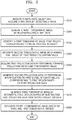
- FIG. 2 is a flowchart of a method of generating a tomographic image, according to an embodiment.
- the tomographic imaging apparatus 1700 may generate a first tomographic image by reconstructing X-ray data at operation S220.
- the tomographic imaging apparatus 1700 may identify, in the first tomographic image, a first region corresponding to a metal particle included in the object at operation S230.
- An example of operation S230 will be described in more detail below with reference to FIG. 3 .
- the tomographic imaging apparatus 1700 may generate a second tomographic image by changing a pixel value of the first region to a certain value, which may be for example a predetermined value, at operation S240.
- a certain value which may be for example a predetermined value
- the tomographic imaging apparatus 1700 may acquire first projection data by performing forward projection on the second tomographic image at operation S250.
- the first projection data may include signal intensity values obtained by converting values of a plurality of pixels in the second tomographic image.
- the tomographic imaging apparatus 1700 may set, based on the position of the first region in the second tomographic image, an interval of projection angles at which forward projection is to be performed on the second tomographic image.
- the tomographic imaging apparatus 1700 may perform forward projection on the second tomographic image at the set intervals, as described in more detail below with reference to FIG. 6 .
- the tomographic imaging apparatus 1700 may change some of_second signal intensity values obtained by linearly interpolating first signal intensity values to their corresponding first signal intensity values, based on a result of comparing the first signal intensity values with the second signal intensity values. An example of the operation will be described in more detail below with reference to FIGS. 9 through 15 .
- the tomographic imaging apparatus 1700 may generate a third tomographic image by reconstructing data acquired by subtracting the first projection data from the second projection data at operation S270.
- the tomographic imaging apparatus 1700 may additionally remove a metal artifact by applying, to the fourth tomographic image, image processing algorithms of the related art for removing metal artifacts, such as linear interpolation and smoothing.
- the tomographic imaging apparatus 1700 may obtain a tomographic image from which a metal artifact is removed by performing the method of generating a tomographic image, according to the embodiment illustrated in FIG. 2 .
- the user may accurately identify an internal structure of the object by using the tomographic image from which the metal artifact is removed.
- metal artifacts may be removed effectively without iterating forward and backward projections.
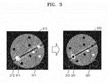
- the tomographic imaging apparatus 1700 may identify a first region 311 corresponding to a metal particle in a first tomographic image 310.
- the tomographic imaging apparatus 1700 may identify, as the first region 311 corresponding to the metal particle, a pixel having a value exceeding a threshold value from among pixels constituting the first tomographic image 310.
- the tomographic imaging apparatus 1700 may identify the first region 311 corresponding to the metal particle by using various methods such as hard thresholding and soft thresholding.
- the tomographic imaging apparatus 1700 may adjust a threshold value based on attribute data of a metal artifact.
- the attribute data of the metal artifact may include a value of a pixel corresponding to the metal artifact.
- the tomographic imaging apparatus 1700 may adjust a threshold value based on an intensity of the metal artifact.
- the tomographic imaging apparatus 1700 may identify the first region 311 based on a second threshold value that is greater than a first threshold value generally used to identify a metal region.
- the tomographic imaging apparatus 1700 may identify the first region 311 based on a third threshold value that is less than the first threshold value.
- the tomographic imaging apparatus 1700 may adjust a threshold value based on the appearance of an artifact that varies depending on a part of the object corresponding to the first tomographic image 310.
- the tomographic imaging apparatus 1700 may identify the first region 311 based on a third threshold value less than the first threshold value.
- the tomographic imaging apparatus 1700 may identify the first region 311 based on the second threshold value greater than the first threshold value generally used to identify a metal region.
- the tomographic imaging apparatus 1700 may identify the first region 311 based on the third threshold value and perform operations S240 through S280 of FIG. 2 . After performing operation S280, the tomographic imaging apparatus 1700 may identify the first region 311 based on the second threshold value and repeat operations S240 through S280.
- the tomographic imaging apparatus 1700 may change a pixel value of the identified first region 311 to a certain value.
- the tomographic imaging apparatus 1700 may refine the first region 311 identified based on a threshold value to correspond to a metal particle by applying techniques such as smoothing, erosion, and dilation to the first region 311. The tomographic imaging apparatus 1700 may then change a pixel value of the refined first region 311.
- the tomographic imaging apparatus 1700 may generate a second tomographic image 320 by changing a pixel value of the first region 311 to a certain value that is a pixel value of a first region 321.
- the tomographic imaging apparatus 1700 may change the pixel value of the first region 311 to 0 or null. In other words, the tomographic imaging apparatus 1700 may generate the second tomographic image 320 by removing the pixel value of the first region 311 corresponding to the metal particle from the first tomographic image 310.
- the tomographic imaging apparatus 1700 may set the certain value based on a pixel value of a second region 312 located near the first region 311.
- the tomographic imaging apparatus 1700 may set the certain value to be different from the pixel value of the second region 312 by a certain amount.
- the tomographic imaging apparatus 1700 may set the certain value to 0 or Null.
- the tomographic imaging apparatus 1700 may set the pixel value of the first region 311 to a certain value that is greater than or less than the pixel value of the second region 312.
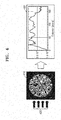
- FIG. 4 illustrates acquisition of projection data by performing forward projection on a tomographic image, according to an embodiment.
- the tomographic imaging apparatus 1700 may acquire first projection data 430 by performing forward projection of projecting a virtual parallel beam 420 onto a second tomographic image 410 at a certain angle.
- the forward projection performed based on the virtual parallel beam 420 requires less computation than forward projection performed based on actually acquired X-ray data.
- metal artifacts may be removed effectively even when a compact tomographic imaging apparatus having a low computing power (e.g., a dental tomographic imaging apparatus) is used.
- FIG. 5 illustrates setting of a projection angle at which forward projection is to be performed, according to an embodiment.
- the tomographic imaging apparatus 1700 may set at least one projection angle at which forward projection is to be performed on a second tomographic image 510, based on positions of a first region 511 corresponding to a metal particle in the second tomographic image 510.
- the tomographic imaging apparatus 1700 may set, based on the position of the first region 511 in the second tomographic image 510, a region ⁇ 1 - ⁇ 2 where the forward projection is to be performed on the second tomographic image 510.
- the tomographic imaging apparatus 1700 may set a projection angle with respect to the set region ⁇ 1 - ⁇ 2 .
- the tomographic imaging apparatus 1700 may perform the forward projection on the second tomographic image 510 at the set projection angle.
- the tomographic imaging apparatus 1700 may acquire first projection data 530 by performing the forward projection on the second tomographic image 510.
- the tomographic imaging apparatus 1700 may identify a region where a metal artifact 513 occurs based on the positions of the first region 511.
- the metal artifact 513 may occur between the metal particles.
- the tomographic imaging apparatus 1700 may perform forward projection on a region ⁇ 1 where the metal artifact 513 is concentrated. In other words, the tomographic imaging apparatus 1700 may set a projection angle with respect to the region ⁇ 1 - ⁇ 2 where the metal artifact 513 is concentrated. The tomographic imaging apparatus 1700 may perform forward projection by projecting a virtual parallel beam onto the second tomographic image 510 a plurality of times at certain intervals within the region ⁇ 1 - ⁇ 2 .
- the forward projection performed only at a certain projection angle requires less computation than forward projection performed in all directions.
- metal artifacts may be removed effectively even when a compact tomographic imaging apparatus having a low computing power (e.g., a dental tomographic imaging apparatus) is used.
- FIG. 6 illustrates setting of an interval of projection angles at which forward projection is to be performed, according to an embodiment.
- the tomographic imaging apparatus 1700 may set, based on a position of a first region 611 in the second tomographic image 610, an interval of projection angles at which beams 621, 623, and 625 are respectively projected onto a second tomographic image 610.
- the tomographic imaging apparatus 1700 may acquire first projection data 631, 633, and 635 by respectively projecting the beams 621, 623, and 625 onto the second tomographic image 610 at the set intervals.
- Each of the first projection data 631, 633, and 635 may include a signal intensity value corresponding to the first region 611, which is obtained by converting a pixel value of the first region 611.
- the tomographic imaging apparatus 1700 may set an interval between projection angles at which the beams 621, 623, and 625 are uniformly projected while rotating around the second tomographic image 610.
- the tomographic imaging apparatus 1700 may set an interval of projection angles to project a beam at intervals of 10° while rotating around the second tomographic image 610.
- the tomographic imaging apparatus 1700 may set, based on the position of the first region 611 in the second tomographic image 610, different intervals of projection angles at which the beams 621, 623, and 625 are respectively projected onto the second tomographic image 610.
- the tomographic imaging apparatus 1700 may set, based on the position of the first region 611 in the second tomographic image 610, at least one region ⁇ 1 and ⁇ 2 where forward projection is to be performed on the second tomographic image 610.
- the tomographic imaging apparatus 1700 may set intervals of projection angles differently for each of the set regions ⁇ 1 and ⁇ 2 .
- the tomographic imaging apparatus 1700 may set an interval of projection angles widely with respect to the region ⁇ 2 where the metal artifact is dispersed while setting an interval of projection angles narrowly with respect to the region ⁇ 1 where the metal artifact is concentrated.
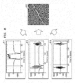
- FIG. 7 illustrates a subtraction image obtained by performing interpolation and then filtering on a signal intensity value in projection data, according to an embodiment.
- the tomographic imaging apparatus 1700 may generate second projection data 720 by performing interpolation on first signal intensity values 711 corresponding to a first region in first projection data 710.
- the tomographic imaging apparatus 1700 may generate third projection data 730 by subtracting the first projection data 710 from the second projection data 720.
- the third projection data 730 may include correction data for a metal artifact.
- the tomographic imaging apparatus 1700 may interpolate the first signal intensity values 711 by using a signal intensity value corresponding to a second region located near the first region.
- the tomographic imaging apparatus 1700 may use a method of performing various interpolation techniques of the related art.
- the tomographic imaging apparatus 1700 may perform linear interpolation, bilinear interpolation, and spline interpolation, but is not limited thereto.
- the third projection data 730 may be projection data to which a filter to be used for reconstructing a tomographic image is applied.
- the tomographic imaging apparatus 1700 may generate the second projection data 720 including second signal intensity values 721 similar to the signal intensity value 712 corresponding to the second region.
- the tomographic imaging apparatus 1700 generates the third projection data 730 by subtracting the first projection data 710 from the second projection data 720, and thus, the third projection data 730 may include correction data for the metal artifact.
- FIG. 8 illustrates generation of a tomographic image including correction data for a metal artifact, according to an embodiment.
- the tomographic imaging apparatus 1700 may generate a third tomographic image by reconstructing third projection data 811, 813, and 815.
- the tomographic imaging apparatus 1700 may reconstruct the third tomographic image 820 from the third projection data 811, 813, and 815 by using various tomographic image reconstruction techniques of the related art.
- the third tomographic image 820 may include correction data for a metal artifact.
- FIG. 9 illustrates a comparison between projection data from which a signal intensity value corresponding to a metal particle is removed and projection data that has undergone interpolation, according to an embodiment.
- FIG. 9 illustrates both first projection data 910, from which a signal intensity value corresponding to a metal particle is removed, and second projection data 920 acquired by linearly interpolating first signal intensity values.
- the first projection data 910 is different from the second projection data 920 in terms of a signal intensity value corresponding to a region that has undergone interpolation.
- the first projection data 910 may include at least one of third signal intensity values 930, which are values greater than second signal intensity values, the second signal intensity values being from among first signal intensity values, or fourth signal intensity values 940 which are less than the second signal intensity values.
- the tomographic imaging apparatus 1700 may select at least one of the third signal intensity values 930 or the fourth signal intensity values 940 to remove a metal artifact.
- the third signal intensity values 930 may be used to remove a white streak metal artifact.
- the white streak metal artifact means a metal artifact occurring when a pixel value of a third region corresponding to the metal artifact is greater than a pixel value of a fourth region located near the third region.
- the fourth signal intensity values 940 may be used to remove a black shading metal artifact.
- the black shading metal artifact means a metal artifact occurring when a pixel value of the third region corresponding to the metal artifact is less than a pixel value of the fourth region located near the third region.
- the tomographic imaging apparatus 1700 may select at least one of the third signal intensity values 930 or the fourth signal intensity values 940 based on a part of an object corresponding to the first tomographic image, for example first tomographic image 310 of FIG. 3 .
- the tomographic imaging apparatus 1700 may select the fourth signal intensity values 940 based on frequent occurrence of a black shading metal artifact.
- the tomographic imaging apparatus 1700 may select the third signal intensity values 930.
- FIG. 10 illustrates projection data generated in order to remove a white streak metal artifact, according to an embodiment
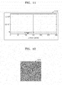
- FIG. 11 illustrates projection data generated in order to remove a white streak metal artifact, according to an embodiment
- FIG. 10 illustrates second projection data 1010 acquired by calculating a difference between the first and second projection data (which may correspond to first projection data 910 and second projection data 920 of FIG. 9 ).
- the tomographic imaging apparatus 1700 may compare first signal intensity values with second signal intensity values in order to remove a white streak metal artifact.
- the tomographic imaging apparatus 1700 may obtain fifth signal intensity values 1020 by calculating, based on a result of the comparing, a difference between second signal intensity values and third signal intensity values 1030 that are values greater than the second signal intensity values from among the first signal intensity values.
- the tomographic imaging apparatus 1700 may acquire the second projection data 1010 by updating the second projection data 920 to include the fifth signal intensity values 1020.
- FIG. 11 illustrates third projection data 1110 acquired by the tomographic imaging apparatus 1700 subtracting the first projection data 910 from the second projection data 1010.
- the third projection data 1110 may include a certain pixel having a signal intensity value less than that of each neighboring pixel.
- the certain pixel may be a pixel corresponding to a region where a white streak metal artifact occurs, and a signal intensity value of the certain pixel may be correction data for removing the white streak metal artifact.
- FIG. 12 illustrates a tomographic image including correction data for removing a white streak metal artifact, according to an embodiment.
- the tomographic imaging apparatus 1700 may reconstruct a third tomographic image 1210 from the third projection data, for example third projection data 1110 of FIG. 11 .
- the third tomographic image 1210 may include correction data for removing a white streak metal artifact.
- the third tomographic image 1210 may include a first pixel with a value less than that of each neighboring pixel.
- the first pixel may correspond to a region where the white streak metal artifact occurs.
- the tomographic imaging apparatus 1700 may remove a white streak metal artifact by adding together attribute data of the white streak metal artifact and a pixel value complementary to the white streak metal artifact.
- the value of the first pixel may correspond to the correction data for removing a white streak metal artifact.
- FIG. 13 illustrates projection data generated for removing a black shading metal artifact, according to an embodiment
- FIG. 14 illustrates projection data generated for removing a black shading metal artifact, according to an embodiment.
- FIG. 13 illustrates second projection data acquired by calculating a difference between the first and second projection data 910 and 920.
- the tomographic imaging apparatus 1700 may compare first signal intensity values with second signal intensity values in order to remove a black shading metal artifact.
- the tomographic imaging apparatus 1700 may obtain fifth signal intensity values 1320 by calculating, based on a result of the comparing, a difference between second signal intensity values and fourth signal intensity values 1330 that are values less than the second signal intensity values from among the first signal intensity values.
- the tomographic imaging apparatus 1700 may acquire the second projection data 1310 by updating the second projection data 920 to include the fifth signal intensity values 1320.
- FIG. 14 illustrates third projection data 1410 that the tomographic imaging apparatus 1700 acquires by subtracting the first projection data 910 from the second projection data 1310.
- the third projection data 1410 may include a certain pixel with a signal intensity value greater than that of each neighboring pixel.
- the certain pixel may be a pixel corresponding to a region where a black shading metal artifact occurs, and a signal intensity value of the certain pixel may be correction data for removing the black shading metal artifact.
- FIG. 15 illustrates a tomographic image including a correction value for removing a black shading metal artifact, according to an embodiment.
- the tomographic imaging apparatus 1700 may reconstruct a third tomographic image 1510 from the third projection data, for example third projection data 1410 of FIG. 14 .
- the third tomographic image 1510 may include correction data for removing a black shading metal artifact.
- the third tomographic image 1510 may include a second pixel with a value greater than that of each neighboring pixel.
- the second pixel may correspond to a region where the black shading metal artifact occurs.
- the tomographic imaging apparatus 1700 may remove a black streak metal artifact by adding together attribute data of the black shading metal artifact and a complementary pixel value.
- the value of the second pixel may correspond to the correction data for removing a black shading metal artifact.
- FIG. 16 illustrates a tomographic image from which a metal artifact is removed, according to an embodiment.
- the tomographic imaging apparatus 1700 may generate a fourth tomographic image 1630 from which a metal artifact is removed based on first tomographic image 1610 and third tomographic image 1620.
- the tomographic imaging apparatus 1700 may generate the fourth tomographic image 1630 from which a metal artifact is removed by adding together the first tomographic image 1610 and the third tomographic image 1620 that includes a pixel value complementary to the metal artifact in the first tomographic image 1610.
- the tomographic imaging apparatus 1700 may generate a fourth tomographic image from which only a white streak metal artifact is selectively removed.
- the tomographic imaging apparatus 1700 may generate a fourth tomographic image from which only a black shading metal artifact is selectively removed.
- the tomographic imaging apparatus 1700 may simultaneously or sequentially perform a method of removing a black shading metal artifact and a method of removing a white streak metal artifact.
- the tomographic imaging apparatus 1700 may additionally remove a metal artifact by applying, to the fourth tomographic image 1630, image processing algorithms of the related art for removing metal artifacts, such as linear interpolation and smoothing.
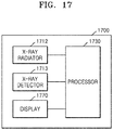
- FIG. 17 is a block diagram of a structure of the tomographic imaging apparatus 1700 according to an embodiment.
- the tomographic imaging apparatus 1700 may be an apparatus for performing at least one of the functions of the tomographic imaging system 100 of FIG. 1 .
- the tomographic imaging apparatus 1700 may include components corresponding to at least one component included in the tomographic imaging system 100 of FIG. 1 .
- the tomographic imaging apparatus 1700 may include the X-ray radiator 1712, the X-ray detector 1713, a display 1770, and a processor 1730.
- the X-ray radiator 1712 may include at least one of the components necessary for radiating X-rays onto an object.
- the X-ray radiator 1712 may include at least one of the gantry 110, the rotating frame 111, the X-ray generator 112, or the rotation driver 114 described with reference to FIG. 1 .
- the X-ray detector 1713 may include at least one of the components necessary for detecting the X-rays radiated by the X-ray radiator 1712 onto the object.
- the X-ray detector 1713 may include at least one of the X-ray detector 113, the readout device 115, the DAS 115-1, or the data transmitter 115-2 described with reference to FIG. 1 .
- the processor 1730 may control all operations of the tomographic imaging apparatus 1700 and a signal flow between the components inside the tomographic imaging apparatus 1700.
- the processor 1730 may include a memory for storing programs or data for performing functions of the tomographic imaging apparatus 1700.
- the processor 1730 may include at least one of the controller 130, the storage 140, or the image processor 150.
- the processor 1730 may include at least one of a general-purpose processor (e. g., a central processing unit (CPU) or a special-purpose processor manufactured to capture a tomographic image and perform image processing.
- the processor 1730 may include a plurality of processors 1730 operating as a single processor.
- the processor 1730 may execute instructions for performing the method of generating a tomographic image according to at least one of the embodiments.
- the processor 1730 may reconstruct a first tomographic image from X-ray data.
- the processor 1730 may identify, in the first tomographic image, a first region corresponding to a metal particle included in the object.
- the processor 1730 may generate a second tomographic image by changing a pixel value of the first region to a certain value.
- the processor 1730 may set the certain value based on attribute data of a metal artifact in the first tomographic image.
- the processor 1730 may set the certain value based on a pixel value of a second region located near the first region.
- the processor 1730 may set the certain value based on a part of the object corresponding to the first tomographic image.
- the processor 1730 may acquire first projection data by performing forward projection on the second tomographic image.
- the processor 1730 may perform forward projection on the second tomographic image by projecting a virtual parallel beam onto the second tomographic image.
- the processor 1730 may set, based on a position of a metal particle, at least one projection angle at which forward projection is to be performed on the second tomographic image and acquire the first projection data by performing the forward projection on the second tomographic image at the set projection angle.
- the processor 1730 may set, based on a position of a metal particle, an interval of projection angles at which forward projection is to be performed on the second tomographic image and acquire the first projection data by performing the forward projection on the second tomographic image at the set intervals.
- the processor 1730 may generate second projection data by performing interpolation on first signal intensity values corresponding to the first region based on the first projection data.
- the processor 1730 may select, based on the attribute data of the metal artifact in the first tomographic image, third signal intensity values that are values greater than second signal intensity values, the second signal intensity values being from among the first signal intensity values or fourth signal intensity values that are values less than the second signal intensity values.
- the processor 1730 may obtain fifth signal intensity values by calculating a difference between the selected third or fourth signal intensity values and the second signal intensity values and generate the second projection data based on the obtained fifth signal intensity values.
- the processor 1730 may select the third signal intensity values based on a comparison result that a pixel value of a third region is greater than that of a fourth region located near the third region, and the fourth signal intensity values based on a comparison result that the pixel value of the third region is less than that of the fourth region.
- the processor 1730 may generate a third tomographic image including correction data for the metal artifact caused by the metal particle by reconstructing data acquired by subtracting the first projection data from the second projection data.
- the third device may execute the computer program product, and may directly perform the method according to embodiments, based on at least one value input from an auxiliary device (e.g., a gantry of tomographic imaging system).
- the auxiliary device may emit X-ray to an object and may obtain information of radiation which passes the object and is detected in an X-ray detector.
- the third device may receive an input of signal information about the detected radiation from the auxiliary device, and may generate an image of an inner part of the object, based on the input radiation information.
Landscapes
- Engineering & Computer Science (AREA)
- Health & Medical Sciences (AREA)
- Life Sciences & Earth Sciences (AREA)
- Medical Informatics (AREA)
- Physics & Mathematics (AREA)
- Theoretical Computer Science (AREA)
- General Health & Medical Sciences (AREA)
- Radiology & Medical Imaging (AREA)
- Nuclear Medicine, Radiotherapy & Molecular Imaging (AREA)
- Pathology (AREA)
- Public Health (AREA)
- Optics & Photonics (AREA)
- Biophysics (AREA)
- Veterinary Medicine (AREA)
- Biomedical Technology (AREA)
- Heart & Thoracic Surgery (AREA)
- Molecular Biology (AREA)
- Surgery (AREA)
- Animal Behavior & Ethology (AREA)
- High Energy & Nuclear Physics (AREA)
- General Physics & Mathematics (AREA)
- Computer Vision & Pattern Recognition (AREA)
- Pulmonology (AREA)
- Quality & Reliability (AREA)
- Apparatus For Radiation Diagnosis (AREA)
Applications Claiming Priority (1)
| Application Number | Priority Date | Filing Date | Title |
|---|---|---|---|
| KR1020190003285A KR20200086919A (ko) | 2019-01-10 | 2019-01-10 | 단층 영상 촬영 장치 및 단층 영상 생성 방법 |
Publications (1)
| Publication Number | Publication Date |
|---|---|
| EP3680860A1 true EP3680860A1 (fr) | 2020-07-15 |
Family
ID=69156343
Family Applications (1)
| Application Number | Title | Priority Date | Filing Date |
|---|---|---|---|
| EP20150964.3A Withdrawn EP3680860A1 (fr) | 2019-01-10 | 2020-01-09 | Appareil d'imagerie tomographique et procédé de génération d'image tomographique |
Country Status (3)
| Country | Link |
|---|---|
| US (1) | US20200226800A1 (fr) |
| EP (1) | EP3680860A1 (fr) |
| KR (1) | KR20200086919A (fr) |
Families Citing this family (4)
| Publication number | Priority date | Publication date | Assignee | Title |
|---|---|---|---|---|
| DE102020203741A1 (de) * | 2020-03-24 | 2021-09-30 | Siemens Healthcare Gmbh | Verfahren und Vorrichtung zum Bereitstellen eines artefaktreduzierten Röntgenbilddatensatzes |
| KR102414094B1 (ko) * | 2020-08-18 | 2022-06-27 | 연세대학교 산학협력단 | Ct영상의 금속 아티팩트 보정 방법 및 장치 |
| KR102302943B1 (ko) | 2020-12-07 | 2021-09-17 | 탈렌트엘엔지(주) | 선박엔진의 연료 공급을 위한 스마트 히팅 시스템 |
| KR102755019B1 (ko) * | 2022-12-26 | 2025-01-21 | 주식회사 레이언스 | 엑스선 영상처리장치 및 엑스선 영상처리시스템 |
-
2019
- 2019-01-10 KR KR1020190003285A patent/KR20200086919A/ko not_active Withdrawn
-
2020
- 2020-01-07 US US16/735,882 patent/US20200226800A1/en not_active Abandoned
- 2020-01-09 EP EP20150964.3A patent/EP3680860A1/fr not_active Withdrawn
Non-Patent Citations (2)
| Title |
|---|
| GJESTEBY LARS ET AL: "Metal Artifact Reduction in CT: Where Are We After Four Decades?", IEEE ACCESS, vol. 4, 13 September 2016 (2016-09-13), pages 5826 - 5849, XP011624799, DOI: 10.1109/ACCESS.2016.2608621 * |
| PUA RIZZA D ET AL: "An image-based approach for reducing metal artifacts in CT", 2014 IEEE NUCLEAR SCIENCE SYMPOSIUM AND MEDICAL IMAGING CONFERENCE (NSS/MIC), IEEE, 8 November 2014 (2014-11-08), pages 1 - 4, XP032879916, DOI: 10.1109/NSSMIC.2014.7430892 * |
Also Published As
| Publication number | Publication date |
|---|---|
| US20200226800A1 (en) | 2020-07-16 |
| KR20200086919A (ko) | 2020-07-20 |
Similar Documents
| Publication | Publication Date | Title |
|---|---|---|
| US10559101B2 (en) | Method and apparatus for generating x-ray tomographic image data | |
| US10952694B2 (en) | Method and apparatus for correcting computed tomography image | |
| EP3143935B1 (fr) | Appareil de tomographie et procédé de reconstruction des images tomographiques | |
| US10143433B2 (en) | Computed tomography apparatus and method of reconstructing a computed tomography image by the computed tomography apparatus | |
| EP3326533B1 (fr) | Dispositif tomographique et procédé de traitement d'image tomographique associé | |
| US10631827B2 (en) | Method and apparatus for processing medical image | |
| EP3680860A1 (fr) | Appareil d'imagerie tomographique et procédé de génération d'image tomographique | |
| KR20170088681A (ko) | 단층 촬영 장치 및 그에 따른 단층 영상 복원 방법 | |
| US10631810B2 (en) | Image processing device, radiation imaging system, image processing method, and image processing program | |
| EP3508125A1 (fr) | Procédé et appareil permettant d'effectuer une imagerie par tomographie (ct) par injection de milieu de contraste | |
| KR101946576B1 (ko) | 의료 영상 장치 및 의료 영상 처리 방법 | |
| EP3349655B1 (fr) | Appareil de tomographie et son procédé de commande | |
| KR20160119540A (ko) | 단층 촬영 장치 및 그에 따른 단층 영상 처리 방법 | |
| KR20170087320A (ko) | 단층 영상 생성 장치 및 그에 따른 단층 영상 복원 방법 | |
| US20200167977A1 (en) | Tomographic image processing apparatus and method, and computer program product | |
| US10565748B2 (en) | Medical imaging apparatus and method of operating the same | |
| CN112545541B (zh) | 医用图像处理装置以及医用图像处理方法 | |
| US20190311503A1 (en) | Apparatus and method for generating tomography image | |
| KR20160072004A (ko) | 단층 촬영 장치 및 그에 따른 단층 영상 복원 방법 |
Legal Events
| Date | Code | Title | Description |
|---|---|---|---|
| PUAI | Public reference made under article 153(3) epc to a published international application that has entered the european phase |
Free format text: ORIGINAL CODE: 0009012 |
|
| STAA | Information on the status of an ep patent application or granted ep patent |
Free format text: STATUS: THE APPLICATION HAS BEEN PUBLISHED |
|
| AK | Designated contracting states |
Kind code of ref document: A1 Designated state(s): AL AT BE BG CH CY CZ DE DK EE ES FI FR GB GR HR HU IE IS IT LI LT LU LV MC MK MT NL NO PL PT RO RS SE SI SK SM TR |
|
| AX | Request for extension of the european patent |
Extension state: BA ME |
|
| STAA | Information on the status of an ep patent application or granted ep patent |
Free format text: STATUS: REQUEST FOR EXAMINATION WAS MADE |
|
| 17P | Request for examination filed |
Effective date: 20200722 |
|
| RBV | Designated contracting states (corrected) |
Designated state(s): AL AT BE BG CH CY CZ DE DK EE ES FI FR GB GR HR HU IE IS IT LI LT LU LV MC MK MT NL NO PL PT RO RS SE SI SK SM TR |
|
| GRAP | Despatch of communication of intention to grant a patent |
Free format text: ORIGINAL CODE: EPIDOSNIGR1 |
|
| STAA | Information on the status of an ep patent application or granted ep patent |
Free format text: STATUS: GRANT OF PATENT IS INTENDED |
|
| RIC1 | Information provided on ipc code assigned before grant |
Ipc: G06T 11/00 20060101AFI20200925BHEP |
|
| INTG | Intention to grant announced |
Effective date: 20201015 |
|
| STAA | Information on the status of an ep patent application or granted ep patent |
Free format text: STATUS: THE APPLICATION IS DEEMED TO BE WITHDRAWN |
|
| 18D | Application deemed to be withdrawn |
Effective date: 20210226 |