EP3681983B1 - Systèmes pour indice d'octane/cétane à la demande sur le point de vente pour des moteurs automobiles - Google Patents
Systèmes pour indice d'octane/cétane à la demande sur le point de vente pour des moteurs automobiles Download PDFInfo
- Publication number
- EP3681983B1 EP3681983B1 EP18796801.1A EP18796801A EP3681983B1 EP 3681983 B1 EP3681983 B1 EP 3681983B1 EP 18796801 A EP18796801 A EP 18796801A EP 3681983 B1 EP3681983 B1 EP 3681983B1
- Authority
- EP
- European Patent Office
- Prior art keywords
- fuel
- market
- octane
- rich
- sale
- Prior art date
- Legal status (The legal status is an assumption and is not a legal conclusion. Google has not performed a legal analysis and makes no representation as to the accuracy of the status listed.)
- Active
Links
Images



Classifications
-
- B—PERFORMING OPERATIONS; TRANSPORTING
- B67—OPENING, CLOSING OR CLEANING BOTTLES, JARS OR SIMILAR CONTAINERS; LIQUID HANDLING
- B67D—DISPENSING, DELIVERING OR TRANSFERRING LIQUIDS, NOT OTHERWISE PROVIDED FOR
- B67D7/00—Apparatus or devices for transferring liquids from bulk storage containers or reservoirs into vehicles or into portable containers, e.g. for retail sale purposes
-
- B—PERFORMING OPERATIONS; TRANSPORTING
- B67—OPENING, CLOSING OR CLEANING BOTTLES, JARS OR SIMILAR CONTAINERS; LIQUID HANDLING
- B67D—DISPENSING, DELIVERING OR TRANSFERRING LIQUIDS, NOT OTHERWISE PROVIDED FOR
- B67D7/00—Apparatus or devices for transferring liquids from bulk storage containers or reservoirs into vehicles or into portable containers, e.g. for retail sale purposes
- B67D7/04—Apparatus or devices for transferring liquids from bulk storage containers or reservoirs into vehicles or into portable containers, e.g. for retail sale purposes for transferring fuels, lubricants or mixed fuels and lubricants
-
- B—PERFORMING OPERATIONS; TRANSPORTING
- B67—OPENING, CLOSING OR CLEANING BOTTLES, JARS OR SIMILAR CONTAINERS; LIQUID HANDLING
- B67D—DISPENSING, DELIVERING OR TRANSFERRING LIQUIDS, NOT OTHERWISE PROVIDED FOR
- B67D7/00—Apparatus or devices for transferring liquids from bulk storage containers or reservoirs into vehicles or into portable containers, e.g. for retail sale purposes
- B67D7/06—Details or accessories
- B67D7/08—Arrangements of devices for controlling, indicating, metering or registering quantity or price of liquid transferred
- B67D7/10—Arrangements of devices for controlling, indicating, metering or registering quantity or price of liquid transferred operated by keys, push-buttons or cash registers
-
- B—PERFORMING OPERATIONS; TRANSPORTING
- B67—OPENING, CLOSING OR CLEANING BOTTLES, JARS OR SIMILAR CONTAINERS; LIQUID HANDLING
- B67D—DISPENSING, DELIVERING OR TRANSFERRING LIQUIDS, NOT OTHERWISE PROVIDED FOR
- B67D7/00—Apparatus or devices for transferring liquids from bulk storage containers or reservoirs into vehicles or into portable containers, e.g. for retail sale purposes
- B67D7/06—Details or accessories
- B67D7/58—Arrangements of pumps
- B67D7/62—Arrangements of pumps power operated
-
- B—PERFORMING OPERATIONS; TRANSPORTING
- B67—OPENING, CLOSING OR CLEANING BOTTLES, JARS OR SIMILAR CONTAINERS; LIQUID HANDLING
- B67D—DISPENSING, DELIVERING OR TRANSFERRING LIQUIDS, NOT OTHERWISE PROVIDED FOR
- B67D7/00—Apparatus or devices for transferring liquids from bulk storage containers or reservoirs into vehicles or into portable containers, e.g. for retail sale purposes
- B67D7/06—Details or accessories
- B67D7/74—Devices for mixing two or more different liquids to be transferred
- B67D7/743—Devices for mixing two or more different liquids to be transferred electrically or electro-mechanically operated
-
- B—PERFORMING OPERATIONS; TRANSPORTING
- B67—OPENING, CLOSING OR CLEANING BOTTLES, JARS OR SIMILAR CONTAINERS; LIQUID HANDLING
- B67D—DISPENSING, DELIVERING OR TRANSFERRING LIQUIDS, NOT OTHERWISE PROVIDED FOR
- B67D7/00—Apparatus or devices for transferring liquids from bulk storage containers or reservoirs into vehicles or into portable containers, e.g. for retail sale purposes
- B67D7/06—Details or accessories
- B67D7/78—Arrangements of storage tanks, reservoirs or pipe-lines
-
- C—CHEMISTRY; METALLURGY
- C10—PETROLEUM, GAS OR COKE INDUSTRIES; TECHNICAL GASES CONTAINING CARBON MONOXIDE; FUELS; LUBRICANTS; PEAT
- C10L—FUELS NOT OTHERWISE PROVIDED FOR; NATURAL GAS; SYNTHETIC NATURAL GAS OBTAINED BY PROCESSES NOT COVERED BY SUBCLASSES C10G OR C10K; LIQUIFIED PETROLEUM GAS; USE OF ADDITIVES TO FUELS OR FIRES; FIRE-LIGHTERS
- C10L1/00—Liquid carbonaceous fuels
- C10L1/04—Liquid carbonaceous fuels essentially based on blends of hydrocarbons
-
- B—PERFORMING OPERATIONS; TRANSPORTING
- B67—OPENING, CLOSING OR CLEANING BOTTLES, JARS OR SIMILAR CONTAINERS; LIQUID HANDLING
- B67D—DISPENSING, DELIVERING OR TRANSFERRING LIQUIDS, NOT OTHERWISE PROVIDED FOR
- B67D7/00—Apparatus or devices for transferring liquids from bulk storage containers or reservoirs into vehicles or into portable containers, e.g. for retail sale purposes
- B67D7/06—Details or accessories
- B67D7/74—Devices for mixing two or more different liquids to be transferred
- B67D2007/745—Devices for mixing two or more different liquids to be transferred for obtaining fuel of a given octane level
- B67D2007/746—Devices for mixing two or more different liquids to be transferred for obtaining fuel of a given octane level by mixing different fuel grades or fuel and oil
-
- B—PERFORMING OPERATIONS; TRANSPORTING
- B67—OPENING, CLOSING OR CLEANING BOTTLES, JARS OR SIMILAR CONTAINERS; LIQUID HANDLING
- B67D—DISPENSING, DELIVERING OR TRANSFERRING LIQUIDS, NOT OTHERWISE PROVIDED FOR
- B67D7/00—Apparatus or devices for transferring liquids from bulk storage containers or reservoirs into vehicles or into portable containers, e.g. for retail sale purposes
- B67D7/06—Details or accessories
- B67D7/74—Devices for mixing two or more different liquids to be transferred
- B67D2007/745—Devices for mixing two or more different liquids to be transferred for obtaining fuel of a given octane level
- B67D2007/748—Devices for mixing two or more different liquids to be transferred for obtaining fuel of a given octane level by mixing fuel with additives, e.g. anti-knocking agents
-
- B—PERFORMING OPERATIONS; TRANSPORTING
- B67—OPENING, CLOSING OR CLEANING BOTTLES, JARS OR SIMILAR CONTAINERS; LIQUID HANDLING
- B67D—DISPENSING, DELIVERING OR TRANSFERRING LIQUIDS, NOT OTHERWISE PROVIDED FOR
- B67D7/00—Apparatus or devices for transferring liquids from bulk storage containers or reservoirs into vehicles or into portable containers, e.g. for retail sale purposes
- B67D7/06—Details or accessories
- B67D7/08—Arrangements of devices for controlling, indicating, metering or registering quantity or price of liquid transferred
- B67D7/16—Arrangements of liquid meters
-
- B—PERFORMING OPERATIONS; TRANSPORTING
- B67—OPENING, CLOSING OR CLEANING BOTTLES, JARS OR SIMILAR CONTAINERS; LIQUID HANDLING
- B67D—DISPENSING, DELIVERING OR TRANSFERRING LIQUIDS, NOT OTHERWISE PROVIDED FOR
- B67D7/00—Apparatus or devices for transferring liquids from bulk storage containers or reservoirs into vehicles or into portable containers, e.g. for retail sale purposes
- B67D7/06—Details or accessories
- B67D7/38—Arrangements of hoses, e.g. operative connection with pump motor
-
- C—CHEMISTRY; METALLURGY
- C10—PETROLEUM, GAS OR COKE INDUSTRIES; TECHNICAL GASES CONTAINING CARBON MONOXIDE; FUELS; LUBRICANTS; PEAT
- C10G—CRACKING HYDROCARBON OILS; PRODUCTION OF LIQUID HYDROCARBON MIXTURES, e.g. BY DESTRUCTIVE HYDROGENATION, OLIGOMERISATION, POLYMERISATION; RECOVERY OF HYDROCARBON OILS FROM OIL-SHALE, OIL-SAND, OR GASES; REFINING MIXTURES MAINLY CONSISTING OF HYDROCARBONS; REFORMING OF NAPHTHA; MINERAL WAXES
- C10G2300/00—Aspects relating to hydrocarbon processing covered by groups C10G1/00 - C10G99/00
- C10G2300/20—Characteristics of the feedstock or the products
- C10G2300/30—Physical properties of feedstocks or products
- C10G2300/305—Octane number, e.g. motor octane number [MON], research octane number [RON]
-
- C—CHEMISTRY; METALLURGY
- C10—PETROLEUM, GAS OR COKE INDUSTRIES; TECHNICAL GASES CONTAINING CARBON MONOXIDE; FUELS; LUBRICANTS; PEAT
- C10G—CRACKING HYDROCARBON OILS; PRODUCTION OF LIQUID HYDROCARBON MIXTURES, e.g. BY DESTRUCTIVE HYDROGENATION, OLIGOMERISATION, POLYMERISATION; RECOVERY OF HYDROCARBON OILS FROM OIL-SHALE, OIL-SAND, OR GASES; REFINING MIXTURES MAINLY CONSISTING OF HYDROCARBONS; REFORMING OF NAPHTHA; MINERAL WAXES
- C10G2300/00—Aspects relating to hydrocarbon processing covered by groups C10G1/00 - C10G99/00
- C10G2300/20—Characteristics of the feedstock or the products
- C10G2300/30—Physical properties of feedstocks or products
- C10G2300/307—Cetane number, cetane index
Definitions
- the present disclosure relates generally to providing enriched octane and cetane fuels for vehicular use, and more particularly to separating a single market fuel into enriched octane and cetane fuels for use in a vehicle at the point of retail sale.
- US7523770 discloses a point-of-sale fuel dispensing system and a method of dispensing fuel.
- Petroleum refineries employ a sophisticated set of disparate systems and their components to convert raw crude into various useful distillates, including liquefied petroleum gas (LPG), gasoline, kerosene, diesel fuel, paraffins, waxes, asphalt, tar or the like.
- LPG liquefied petroleum gas
- processes used in a conventional refinery include coking, visbreaking, catalytic cracking, catalytic reforming, hydroprocessing, alkylation and isomerization.
- transportation fuels such as diesel fuel and gasoline
- supplemental operations such as fuel blending, fuel additives or the like may be employed at the refinery in order to meet particular goals for octane or cetane ratings, volatility, stability, emissions control or the like.
- ICE internal combustion engine
- GCI gasoline compression ignition
- HCCI homogeneous charge compression ignition
- RCCI reactivity controlled compression ignition
- CI diesel compression ignition
- SI gasoline spark ignition
- a retail purchaser may select from one of a few options of fuel grade with which to dispense to his or her SI-powered vehicle by selecting a button on a pump assembly or related fuel dispensing apparatus.
- This blending pushes the extra infrastructure cost farther down the oil supply chain.
- the point-of-sale retailer needs to have a ready supply of different grades of market fuel from which such on-site blending operations may proceed.
- the present disclosure promotes the separation of a single market fuel that is situated at an on-site retail fueling station (also referred to as a filling station) into fuels of different octane or cetane ratings to meet the needs of a vehicle with a particular ICE, regardless of the mode of ICE operation (for example, SI, CI, GCI or the like).
- an on-site retail fueling station also referred to as a filling station
- ICE for example, SI, CI, GCI or the like.
- an on-demand system can deliver lower octane (for SI engines) or lower cetane (for CI or GCI engines) fuel to the ICE, while under high-load conditions for such engines, it can deliver enhanced quantities of octane or cetane, respectively.
- Such a system and an approach as contained in the present disclosure has the flexibility to provide a continuous range of fuels of different octane or cetane specifications from a single, local market fuel in a point-of-sale structure that is not present at the refinery and, as such, could not be replicated by merely scaling-down a refinery-based customization operation.
- point-of-sale structure is dissimilar from point-of-sale blending systems in that redundant infrastructure-such as multiple storage tanks for different grades of market fuel-are not required. In this way, it can provide substantially instantaneous delivery of a fuel that is tailored to the needs of an individual vehicle that in turn avoids or reduces the expenses associated with so-called "octane giveaway", as well as reducing the risk of producing unused fuels.
- market fuel includes those SI or CI fuels that arrive on-site at the filling station or related retail point-of-sale from the refinery or other upstream facility in their conventional ready-to-be-dispensed formulas.
- a gasoline-based market fuel may possess a research octane number (RON) of roughly 85 to 100
- a diesel-based market fuel may possess a cetane number (CN) of roughly 40 to 60, where both may further include conventional additives such as those for antiknock improvement, cold-flow performance boosters, deposit control, detergents, emissions control, friction reduction or the like.
- a market fuel may additionally be subjected to conventional or yet-to-be developed blending or related modification at the point-of-sale.
- the ability to produce selective OOD and COD at the point of retail sale permits the owner or operator of such fueling or filling station to use market fuels of relatively low grade (for example, low octane) and separate such fuel on-site as a way to avoid having to keep a large reserve of high grade fuel (with its concomitantly higher processing cost), as well as reduce the environmental impact (such as carbon emissions) associated with large-scale fuel processing activities.
- relatively low grade for example, low octane
- such localized, readily-available supply of higher grades manufactured at the point of retail sale is useful for original equipment manufacturers (OEMs) in that it allows them more design flexibility to downsize ICEs in an attempt to achieve one or both of better fuel economy and higher performance.
- FIG. 1 a general view depicting various portions scheme of a point-of-sale fuel dispensing system 100 for use in fueling a vehicle 10 at a retail filling station is shown, where the vehicle 10 includes (among other things) a fuel supply port 20, fuel line 30, fuel tank 40, ICE 50 and electronic control unit (ECU) 60 that can provide at least some operational control over vehicle 10 based on sensed data and known parameters the latter of which can be provided through engine performance maps 70 that are stored in memory as either lookup tables, algorithms or the like.
- ECU electronice control unit
- the engine performance maps 70 and other information contained within or otherwise accessible through memory by the ECU 60 may be used by the vehicle 10 manufacturer in order to recommend to the customer which grade of fuel to select, while in another form, the customer may make such selection based on his or her own known driving habits.
- the vehicle 10 manufacturer may be used by the vehicle 10 manufacturer in order to recommend to the customer which grade of fuel to select, while in another form, the customer may make such selection based on his or her own known driving habits.
- SUVs sport utility vehicles
- the fuel storage capacity of the fuel tank 40 is between roughly ten gallons and twenty five gallons, although it will be appreciated that such sizes may be larger or smaller, depending on the size of the vehicle 10, and that all such variants are deemed to be within the scope of the present disclosure.
- the fuel tank 40 is limited to those containers and related vessels that are fluidly coupled to the ICE 50 that is providing propulsive power to vehicle 10.
- fuel-containing tanks that are situated on or otherwise carried by a vehicle and that are for use in storing fuel in transit rather than as an energy source for the ICE 50 and associated transportation needs of vehicle 10 are not deemed to be fuel tanks for the purpose of the present disclosure.
- such fuel storage capacity of the fuel tank 40 is that which is designed and built in conjunction with the as-manufactured vehicle 10 such that for fueling purposes, an amount of fuel being dispensed from the point-of-sale fuel dispensing system 100 does not exceed such fuel storage capacity of the vehicle 10 and its fuel tank 40.
- the point-of-sale fuel dispensing system 100 is made up of numerous components including a market fuel storage tank 200, a pump assembly (also referred to as a fuel dispenser) 300, fuel conduit 400, an optional fuel pressurizing device 500, separation unit 600, various enriched fuel product tanks (collectively 700, individually 700A, 700B), controller 800, as well as numerous sensors S that can acquire operational data of the various system components.
- a vehicle 10 in need of refueling is placed adjacent the pump assembly 300 so that-depending on the grade or specification of the fuel needed to best operate the vehicle 10- a customer may pay for and select an appropriate fuel grade that may be produced and stored on-site.
- the grade of fuel selected by the customer may substantially comprise the market fuel F M , while in another form, it may comprise the market fuel F M that has been augmented by a suitable amount of octane-rich or cetane-rich fuel components F O and F C as produced by system 100, as well as the market fuel F M with or without the inclusion of the octane-rich or cetane-rich fuel components F O and F C along with oxygenates (such as ethanol, tertiary butyl alcohol (TBA) or methyl tertiary butyl ether (MTBE)), aromatics (such as benzene, toluene or xylene) or other additives for the octane-rich fuel component F O or nitrates (for example, 2-ehtylhexyl nitrate) or peroxides (for example, di-tertiary-butyl-peroxide) for the cetane-rich fuel component F C , all as will be
- a fuel or fuel component is deemed to be octane-rich when it has a concentration of iso-octane (C 8 H 18 ) or other knock-reducing components that is greater than that of the readily-available market fuel F M from which one or more separation activities have been employed.
- a fuel would be considered to be octane-rich if it had a research octane number (RON) of greater than about 91-92 or an anti-knock index (AKI) of greater than about 85-87 for a so-called regular grade unleaded fuel, with respectively slightly higher values for mid-grade unleaded fuel and premium unleaded fuel.
- a fuel would be considered to be cetane-rich if it had a cetane number (CN) of greater than about 40-45 (for most of the United States market, with suitable variations elsewhere).
- CN cetane number
- energy may come in the form of heat such as that needed for volatility-based separation or extraction.
- energy may come in the form of pressure such as from a pump or related mechanical pressurizing device 500; this latter form may be used in conjunction with membrane-based separation processes or any other process that requires additional pressure to the market fuel F M .
- the market fuel storage tank 200 is situated underground on the premises of a retail refueling station, and may be configured as a generally cylindrical-shaped vessel sized to contain between about 1,000 gallons and 30,000 gallons of market fuel F M that can be introduced through a ground-based fill cap 200A and a fill line 200B.
- market fuel F M may be withdrawn from the market fuel storage tank 200 through the operation of the fuel pressurizing device 500 working in conjunction with a fuel uptake line 230 that may form a part of fuel conduit 400.
- the market fuel storage tank 200 may be stored above ground on the retail refueling station premises such that either the underground or above ground variants are deemed to be within the scope of the present disclosure.
- the pump assembly 300 includes a housing 310, a nozzle 320 for dispensing fuels to vehicle 10, a valve-based metering device 330 and customer interface 340.
- customer interface includes those interfaces that permit a customer to generate commands, data, or other input that can be used by other point-of-sale hardware or software to facilitate the sale and dispensing of fuel and, potentially, other goods and services.
- the customer interface 340 includes a keypad 342 or related input device to permit the customer to initiate and pay for a particular fuel purchase, a display screen 344 for displaying visual information, and a card reader 346.
- the keypad 342 and display screen 344 may be integrated into a display-based touch-screen or other known graphical user interface with input/output functionality.
- the customer interface 340 may include a wireless communication portal or other input device.
- the display screen 344 may be configured to provide not just fuel grade options, but also whether the fuel being selected includes octane boosters, deposit control additives, combustion modifiers, friction modifiers or the like (for use when the fuel being dispensed exhibits significant gasoline-like properties), as well as cetane boosters, detergents, cold-flow performance additives, lubricity additives or the like (for use when the fuel being dispensed exhibits significant diesel fuel-like properties) are available for dispensing, as well as options for a particular type and amount of such additive to be dispensed.
- the fuel being selected includes octane boosters, deposit control additives, combustion modifiers, friction modifiers or the like (for use when the fuel being dispensed exhibits significant gasoline-like properties), as well as cetane boosters, detergents, cold-flow performance additives, lubricity additives or the like (for use when the fuel being dispensed exhibits significant diesel fuel-like properties) are available for dispensing, as well as options for
- a processor-based controller 350 may be disposed within the housing 310 and coupled to the various components that make up the pump assembly 300 to allow the customer to select the fuel grade, as well as to pay for the fuel being purchased.
- the nozzle 320 provides a termination point for a hose 360 or other fluid tube that may make up a portion of fuel conduit 400.
- the pump assembly 300 and fuel conduit 400 are sized to accommodate flows of up to about ten to fifteen gallons per minute (subject to various jurisdiction-mandated limitations), whereas for larger tanks (in the case of larger passenger or commercial vehicles, heavy trucks, vans, buses, coaches or the like), the size of the fuel conduit 400 may be made larger (for example, between about thirty and thirty five gallons per minute (again, depending on jurisdiction-imposed limitations).
- the metering device 330 may be in the form of a chamber, valve or other configuration disposed in or adjacent the housing 310 to function as a way to optionally introduce oxygenates, aromatics, nitrates, peroxides or other fuel additives that may be stored on-site, such as will be discussed in more detail in conjunction with FIGS. 2 through 4 .
- the metering device 330 may also be used in conjunction with controller 350 to ensure that the desired proportion of one or more of the market fuel F M , octane-rich fuel component F O and cetane-rich fuel component F C are mixed together in accordance with the fuel grade that has been selected by the customer.
- any such mixing based on the customer choice made through the customer interface 340 may be based on correlations to known, predetermined mixed fuel formulas such that these formulas may be retrieved via lookup table in memory or other similar data structures that can be accessed by metering device 330 or controller 350.
- customer-specific information may be stored in memory for use by the controller 800 to expedite subsequent purchases at the same filling station (or other commonly-owned filling stations that share such customer-specific information) through correlation between the each customer's account number or related identifier and a database of previously-purchased fuels.
- details associated with the chosen fuel grade-as well as the corresponding cost- may also be visually indicated on the display screen 344 to allow the customer to select the fuel grade and proceed with the desired purchase such that the proper fuel may be conveyed through the fuel conduit 400, metering device 330, hose 360, nozzle 320 and into vehicle 10 though its fuel supply port 20, fuel line 30 and fuel tank 40.
- the fuel pressurizing device 500 is configured as a pump, such as a kinetic-based submersible pump that achieves its pressurizing function through a centrifugally-rotating impeller or a positive-displacement suction pump.
- a pump may perform both the pressurizing function for the market fuel F M through the fuel conduit 400 and the pump assembly 300 as well as the pressurizing function for the market fuel F M to pass through the separation unit 600 in order to produce the octane-rich fuel component F O and cetane-rich fuel component F C .
- there may be more than one pump such that one may be dedicated to one or the other of pressurizing market fuel F M for direct delivery to the pump assembly 300 while another is used or pressurizing market fuel F M for delivery to the separation unit 600 for the production of the octane-rich fuel component F O and cetane-rich fuel component F C .
- pressurizing market fuel F M for direct delivery to the pump assembly 300 while another is used or pressurizing market fuel F M for delivery to the separation unit 600 for the production of the octane-rich fuel component F O and cetane-rich fuel component F C .
- Either variant is deemed to be within the scope of the present disclosure.
- energy used to power the fuel pressurizing device (or devices) 500 as a way to support the market fuel F M separation processes discussed in the present disclosure processes can come from a variety of sources 510, 520, 530 and 540, some of which are renewable.
- renewable energy sources may include solar energy through a suitable photovoltaic device 510.
- such energy may be provided by wind power, such as through wind turbine 520 or other wind-responsive rotary device.
- the energy source may be provided by geothermal power 530, including dry steam geothermal power stations, flash steam geothermal power stations or the like.
- the energy may be provided by biomass or hydroelectric sources.
- the fuel pressurizing device 500 may in one form be a pump that is adapted to receive electric power from one or more of these renewable energy sources 510, 520, 530 and 540.
- the energy may be provided in nonrenewable forms.
- non-renewable energy sources may include the burning of fossil fuels in an ICE (such as a ground-based power unit or related stationary version of ICE 50) to generate mechanical power directly or as electrical power that may generate mechanical power indirectly.
- non-renewable energy sources may include a direct supply of electricity from the electrical grid 540 from an electric power generating station or other conventional alternating current power source such that a conventional induction or permanent-magnet electric motor (not shown) is directly coupled to the pump or other fuel pressurizing device 500.
- the energy may also be converted into a different usable form (such as heat to power or the like) using a suitable conversion device in the form of a motor similar to the previously-mentioned electric motor.
- the fuel pressurizing device 500 can receive the market fuel F M through the fuel uptake line 230 in order to pressurize it for delivery through portions of the fuel conduit 400 to the separation unit 600.
- the energy sources discussed in conjunction with the point-of-sale fuel dispensing system 100 are available from the filling station's local environment.
- one or more of the renewable and non-renewable sources of energy can be combined to take advantage of different conditions as a way to ensure that a steady, reliable way to deliver sufficient power to achieve the desired degree of market fuel F M pressurization and subsequent separation.
- the fuel pressurizing device 500 might not be needed, such as those situations associated with the more efficient heat-based separation energy for volatility-based separation or extraction where renewable sources such as solar thermal may be employed.
- a storage device 550 that in one form may constitute a charge-storage device such as a battery or the like for later use by the point-of-sale fuel dispensing system 100.
- Such storage is particularly useful for other operational periods that may coincide with times where such renewable energy source is not immediately available, such as when there is an inadequate amount of wind or sunlight.
- the separation unit 600 is fluidly coupled to the fuel pressurizing device (or devices) 500 such that the incoming market fuel F M is operated upon by one or more reaction chambers that make up the separation unit 600.
- the separation unit 600 is configured to have membrane-based or extractive-based reaction chambers. Such configurations avoid the complexity, large energy consumption and additional infrastructure difficulties that are associated with distillation-based and absorption-based approaches, making them particularly applicable for use in the scale required in a retail filling station environment.
- the separation unit 600 may be made up of numerous sub-units such that one sub-unit (for example, a membrane-based sub-unit) may be particularly configured to generate a cetane-rich fuel component F C , while another such sub-unit (for example, an extractive-based sub-unit) may be particularly configured to generate an octane-rich fuel component F O .
- one sub-unit for example, a membrane-based sub-unit
- another such sub-unit for example, an extractive-based sub-unit
- such sub-units may be configured to work sequentially with one another.
- hydrodynamic-based and diffusion-based mechanisms may be employed in configurations when the reaction chamber or chambers that make up the separation unit 600 include a membrane-based separator.
- membranes may be used to facilitate pressure difference-driven separating activities and concentration difference-driven separating activities.
- Such membranes may be generally spiral wound, hollow fiber or other known shapes, while also being made from various polymers, composites, ceramics or other materials that include additives in order to impart particular separating qualities.
- such membranes may be made to selectively pass particular components of a fluid mixture based on various criteria of the fluid itself, such as the polar or non-polar nature of the molecules, molecular weight of the molecules, as well as other chemical or physical properties of such fluid.
- membranes may be such that chemical potential-difference-driven separating activities are included. All such membrane variants are deemed to be within the scope of the present disclosure, particularly as they relate to separating at least a portion of the market fuel F M into its octane-rich and cetane-rich fuel components F O , F C that may be used in ICE 50.
- the reaction chamber or chambers that make up the separation unit 600 include an extractive-based separator, where differences in the solubilities of various compounds within a liquid mixture can be employed along with mixer-based, column-based or centrifugal-based extraction equipment.
- the relative solubility difference between the market fuel F M being introduced and a solvent can be used in either a batchwise or continuous manner in a way that is well-suited to fuel formulations where the fuel components have close boiling points or otherwise exhibit several azeotropes that do not lend themselves to simple distillation-based separation techniques.
- various ionic liquids or organic solvents may be used, depending on the precise nature of the components being separated, as is understood by those skilled in the art.
- the reaction chamber may be configured as a container, vessel or the like to combine a pair of immiscible solvents such that after cessation of agitation or other mixing, the solvents striate, at which time the market fuel F M is introduced such that a solute such as the octane-rich fuel component F O may be extracted.
- the difference in solubilities of the solvents in the reaction chamber cause a compound that includes the octane-rich solute to transfer from one of the solvents to the other.
- a funnel (not shown) or related device may be used to help with the extraction.
- the effluent octane-rich and cetane-rich fuel components F O and F C are then routed through a portion of the fuel conduit 400 into the respective enriched fuel product tanks 700.
- the enriched fuel product tanks 700 may hold up to about one percent of the amount of fuel stored in the market fuel storage tank 200 (that is to say, about 400 liters of enriched fuel in situations where the market fuel storage tank 200 contains about 40,000 liters of market fuel F M ,).
- the octane-rich and cetane-rich separated fuel components F O and F C can optionally receive one or both of an octane additive and a cetane additive that are contained within respective booster tanks 900A, 900B to help tailor the fuel to a desired certain octane or cetane rating prior to being conveyed to the pump assembly 300.
- a metering device (as shown in FIG. 2 ) may be fluidly disposed between the booster tanks 900A, 900B and the enriched fuel product tanks 700 in order to promote the inclusion of the octane booster as an anti-knock agent and the cetane booster as an ignition accelerator.
- the booster tanks 900A, 900B may hold up to about five percent of the amount of market fuel F M that is present within the market fuel tank 200.
- the booster tanks 900A, 900B may be sized to hold about 2,000 liters of additives in situations where the market fuel tank 200 is capable of holding about 40,000 liters.
- Controller 800 is used to receive data from sensors S and provide logic-based instructions to the various parts of point-of-sale fuel dispensing system 100.
- the controller 800 could manage the fuel flow from either the market fuel storage tank 200 or one or both of the product tanks 700 where the two fuels corresponding to OOD or COD may be injected separately or together, the latter by blending through the metering device 330 at different ratios depending on fuel grade selected by the point-of-sale purchaser.
- controller 800 may be a singular unit such as shown notionally in FIG. 1 , or one of a distributed set of units throughout the point-of-sale fuel dispensing system 100.
- controller 800 may be configured to have a more discrete set of operational capabilities associated with a smaller number of component functions such as those associated solely with the operation of the pump assembly 300, while in anther configuration, controller 800 may have a more comprehensive capability such that it acts to control a larger number of components within the point-of-sale fuel dispensing system 100, such as the various pumps, valves, actuators and related flow control devices that define fuel conduit 400, and that all such variants, regardless of the construction and range of functions performed by the controller 800, are deemed to be within the scope of the present disclosure.
- the controller 800 may be configured as an application-specific integrated circuit (ASIC).
- ASIC application-specific integrated circuit
- controller 800 is provided with one or more input/output (I/O) 810, microprocessor or central processing unit (CPU) 820, read-only memory (ROM) 830, random-access memory (RAM) 840, which are respectively connected by a bus 850 to provide connectivity for a logic circuit for the receipt of signal-based data, as well as the sending of commands or related instructions.
- I/O input/output
- CPU central processing unit
- ROM read-only memory
- RAM random-access memory
- Various algorithms and related control logic may be stored in the ROM 830 or RAM 840 in manners known to those skilled in the art.
- Such control logic may be embodied in a preprogrammed algorithm or related program code that can be operated on by controller 800 and then conveyed via I/O 810 to the various components of the point-of-sale fuel dispensing system 100 being acted upon.
- sensors may comprise pressure sensors, temperature sensors, optical sensors, acoustic sensors, infrared sensors, microwave sensors, timers or other sensors known in the art for receiving one or more parameters associated with the operation of the point-of-sale fuel dispensing system 100 and associated components.
- the controller 800 may be implemented using model predictive control schemes such as the supervisory model predictive control (SMPC) scheme or its variants, or such as multiple-input and multiple-output (MIMO) protocols or the like.
- SMPC supervisory model predictive control
- MIMO multiple-input and multiple-output protocols or the like.
- a customer fuel choice such as that entered through customer interface 340 and received by the controller 800 can be compared to a predetermined table, map, matrix or algorithmic value so that based on the desired fuel type, the controller 800 may instruct the other components that make up the point-of-sale fuel dispensing system 100 to adjust or dispense a fuel mixture that best comports with the selected fuel grade.
- controllers 350, 800 may be separate devices that can work in conjunction with one another such that the production of the octane-rich and cetane-rich separated fuel components F O and F C are governed by controller 800 while any blending and other dispensing-related functions are governed by controller 350, and that it will be appreciated that either variant is within the scope of the present disclosure.
- controller 800 may be preloaded with various parameters (such as ambient pressure and temperature conditions) into a lookup table that can be included in the ROM 830 or RAM 840.
- controller 800 may include one or more equation- or formula-based algorithms that permit the processor 820 to generate a suitable logic-based control signal based on inputs from various sensors, while in yet another form, controller 800 may include both lookup table and algorithm features to promote its fuel monitoring, mixing and dispensing functions.
- controller 800 is useful in promoting customizable fuel strategies that may be configured for a particular engine operational mode, such as GCI, where taking advantage of a particular fuel's inherent properties (such as-for example-ignition delay which helps to promote additional fuel-air mixing), more efficient, lower-emissions operation of ICE 50 may be achieved.
- a properly-customized fuel being delivered to vehicle 10 through the point-of-sale fuel dispensing system 100 under instructions as provided by controller 800 could be used for the delivery of fuel in PPCI, HCCI, RCCI or related modes of operation of ICE 50, that would benefit from a more precise fuel formulation.
- operation of controller 800 may be based on empirical correlations such that desired fuel properties may be predicted. This in turn allows the controller 800 to regulate fuel separation and operating conditions of the system 100.
- the sources may include one or more photovoltaic cells 510 that are used to convert solar energy to electrical energy to run the fuel pressurizing device 500 in the form of a pump so that at least some of the market fuel F M becomes pressurized such that it can be delivered through a portion of the fuel conduit 400 to the separation unit 600 with one or more reaction chambers in the form of a membrane.
- the membrane separates the market fuel F M into a retentate stream 610 and a permeate stream 620, each of which has a different octane or cetane rating.
- the solar energy may be provided in the form of concentrated solar power (CSP) or the like that may be used along with the fuel pressurizing device 500 and separation units 600 to help create the desired octane-rich or cetane-rich fuel components F O , F C .
- CSP concentrated solar power
- mixers 910A, 910B may be placed along fuel conduit 400 such that they are fluidly downstream of the separation unit 600 and octane and cetane booster tanks 900A, 900B, while being fluidly upstream of the enriched fuel product tanks 700A, 700B.
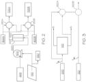
- the separated (that is to say, octane-rich and cetane-rich) fuel components F O , F C that are introduced into the_enriched fuel product tanks 700A, 700B may be mixed with additional octane or cetane boosters that is stored in the respective octane booster tank 900A and cetane booster tank 900B (all as shown in FIG.
- one or the other of the separated octane-rich and cetane-rich fuel components F O , F C can be blended with the one of the incoming market fuels F ML , F MH that was not subjected to the separating actions of the separation unit 600 of FIG. 1 in order to further customize a specific fuel grade for use by the point-of-sale customer.
- F O , F C can be blended with the one of the incoming market fuels F ML , F MH that was not subjected to the separating actions of the separation unit 600 of FIG. 1 in order to further customize a specific fuel grade for use by the point-of-sale customer.
- the separated octane-rich fuel component F O is shown being blended in mixer 920A with market fuel F M that is being delivered from the market fuel storage tank 200, as well as optionally in a second mixer 920B with the second (higher RON) market fuel F MH that is being delivered from the additional market fuel storage tank 210.
- the cetane-rich fuel component F C may in one form be used as GCI fuel, while the octane-rich fuel component F O - as well as any blending it may have with the second (higher RON) market fuel F MH - can be used as a higher-octane SI fuel, especially in high-performance versions of vehicle 10 that are configured with ICEs 50 that have a high compression ratio.
- Controller 800 (as shown in FIG. 1 ) may have suitable logic built in to allow various manipulation of the various valves, pumps and other flow control equipment that makes up the fuel conduit 400 in order to respond to the customer request as entered through the customer interface 340 as a way to provide the desired grade of fuel to the vehicle 10 through the pump assembly 300.
- a network of selective separators and an associated portion of fuel conduit 400 may be used as an example of what can be achieved when the point-of-sale fuel dispensing system 100 is further equipped to perform separation of certain chemical species from either the market fuel F M or the octane-rich or cetane-rich fuel components F O , F C is shown.
- logic embedded in controller 800 may be used along with the various valves, piping and pumps that are used to convey fluids through the fuel conduit 400 to ensure the selective routing of the market fuel F M or the octane-rich or cetane-rich fuel components F O , F C being manipulated by such additional equipment.
- the additional equipment may be in the form of one or more selective oxygenate separators 1010, 1020 and one or more selective aromatic separators 1030, 1040 all of which may be fluidly disposed along fuel conduit 400 such that they are fluidly downstream of a pair of market fuel storage tanks 200, 210 to receive respective low and relatively high RON fuels F ML , F MH in a manner generally similar to that depicted in FIG. 3 , while being fluidly upstream of the enriched fuel product tanks 700A, 700B such that any additional separation of oxygenates or aromatics may be performed as a way to further tailor the properties of the low and relatively high RON fuels F ML , F MH to a selection made by a purchaser at the customer interface 340.
- a network of dedicated selective oxygenate separators 1010, 1020 and selective aromatic separators 1030, 1040 may be used to achieve some measure of octane or cetane customization.
- valving and related fuel flow manipulation approaches may be used to reduce component redundancy of the network of selective oxygenate separators 1010, 1020 and selective aromatic separators 1030, 1040 such that depending on the fuel grade selected, the corresponding incoming market fuel F M may be routed through one or both of a single oxygenate separator and a single aromatic separator in order to achieve the desired changes in the fuel's octane or cetane number, and that both variants are deemed to be within the scope of the present disclosure.
- such a network is deemed to be present irrespective of whether each of the aromatic and oxygenate separators is configured as a single unit or multiple units, so long as such selective oxygenate separators 1010, 1020 and selective aromatic separators 1030, 1040 are made to cooperate with the valves, piping and other flow control components associated with the respective portions of the fuel conduit 400 in response to instructions from controller 800 as a way to customize the fuel being delivered to the pump assembly 300 in response to the customer request.
- the selective oxygenate separator 1010 acts to bifurcate the stream such that the resulting cetane-rich fuel component F C and octane-rich fuel component F O proceed along different paths, the first to either a mixer 910B or one or both of the cetane-rich fuel component tank 700B and cetane booster tank 900B, and the second to either a mixer 910A or the octane booster tank 900A (all as shown in FIG. 1 ).
- the lower RON market fuel F ML may be made (through the operation of valve V) to instead be routed directly to the selective aromatics separator 1030 for similar generation of a cetane-rich fuel component F C and an octane-rich fuel component F O .
- the incoming lower RON market fuel F ML may be made to pass in a cascaded manner sequentially through both of the selective oxygenates separator 1010 and the selective aromatics separator 1030, where the choice of the first or second paths is dictated by controller 800 which in turn is based on external factors such as customer choice, local environmental mandates or then like.
- the incoming fuel market fuel F M may traverse a relatively similar one of the paths through one or both of the selective oxygenates separator 1020 and the selective aromatics separator 1040.
- the lower RON effluent (that is to say, a cetane-rich fuel component F C ) of the selective oxygenates separator 1020 may be delivered directly through a low RON path to become input for a GCI mode of operation, while the higher RON effluent (that is to say, an octane-rich fuel component F O ) may be delivered directly through a high RON path to become input for an SI (particularly a high-performance/high compression ratio) mode of operation.
- the high RON fuel fraction enters the selective aromatics separator 1040 such that additional low and high octane effluent may be delivered to the SI vehicular fuel tank 40 via pump assembly 300.
- the octane-rich fuel component F O (whether rich in aromatics or oxygenates) can be used as an octane booster, high octane fuel, chemical feedstock, power generation fuel, marine fuel or other application where the higher octane rating would be required.
- the cetane-rich fuel component F C that has a relatively low concentration of aromatics or oxygenates can be used as GCI fuel.
- the various effluents can be mixed together to form a GCI fuel of a different octane rating.
- the concentrations and relative proportions of the oxygenates and aromatics may be blended in a variety of ways to allow the point-of-sale fuel dispensing system 100 to provide a highly customized final fuel product for dispensing.
- FIGS. 5A and 5B predicted and experimental data collected from pilot plant labs based on flash distillation on two fuels of different grades (in particular, gasoline with octane ratings of 91 RON and 95 RON) is shown.
- FIG. 5A the results based on an Aspen HYSYS ® chemical process simulation software analysis for separating the 91 RON gasoline fuel into octane-rich and cetane-rich fuel components F O , F C is shown.
- Aspen HYSYS ® chemical process simulation software analysis for separating the 91 RON gasoline fuel into octane-rich and cetane-rich fuel components F O , F C is shown.
- the difference in RON between the vapor and liquid phases increases along with the condensed vapor flow that in turn increases as the distillation temperature increases.
- results for changes in RON based on changes in condensed vapor flow for an input fuel stream of 91 RON gasoline using a flash distillation-based experimental setup is shown.
- the experimental setup employed flash distillation with which to achieve the fuel separation.
- the changes in octane or cetane levels-if produced by the membrane or extractive techniques mentioned in the present disclosure would show similar octane bifurcation.
- CFR Cooperative Research Committee
- the samples were profiled using gas chromatography (GC) that showed that fuel separation into different octane ratings can be achieved, and that as vapor flow increases, the octane rating of the octane-rich fuel component F O also increases.
- GC gas chromatography
- the fuel represented by the upper curve could be used in a high RON engine such as an SI-configured ICE 50 in general, and a high-compression SI-configured ICE 50 in particular.
- the fuel represented by the lower curve could be used in a low RON engine such as a GCI-configured ICE 50.
- FIGS. 6A and 6B predicted RON changes based on a flash distillation process where increases in flash tank temperature correspond to increases in octane separation for two different US market gasoline samples are shown.
- the two fuels represent a summer blend in FIG. 6A and a winter blend in FIG. 6B where such blends may compensate for differences in warm weather and cold weather fuel vapor pressures.
- These simulation results show that although the RON separation performance is different between the two samples, they both indicate that a significant amount of RON separation may be achieved.
- FIGS. 7A and 7B predicted RON separation behavior for two market fuels F M - one with 91 RON and one with 95 RON-using the Aspen HYSYS ® chemical process simulation software analysis for a liquid-liquid extraction-based process is shown.
- the simulation was conducted at two different temperatures (130° C as shown in FIG. 7A and 170° C as shown in FIG. 7B ) such as that available with heat supplied from a thermoelectric generator (TEG) or the like.
- TOG thermoelectric generator
- the simulation was conducted using different solvent/fuel ratios.
- RON separation increases as the flash tank temperature increases, although the impact of changes in the solvent/fuel ratio appears to have only a small to negligible effect on RON separation for both types of gasoline.
- FIGS. 8A and 8B benefits associated with using oxygenates as a way to provide increases in a blended fuel RON are shown.
- profiles of aromatics content and RON are shown for the blending of two different market fuels F M .
- a comparison of the two figures show that other considerations may need to be taken into consideration when trying to meet RON specifications with blended fuels.
- the number of design choices for achieving the desired RON levels in the blended fuel may be limited.
- the regions R show where such high and low RON fuel blending is possible without violating aromatics requirement upper limits.
Landscapes
- Engineering & Computer Science (AREA)
- Mechanical Engineering (AREA)
- Chemical & Material Sciences (AREA)
- Oil, Petroleum & Natural Gas (AREA)
- Chemical Kinetics & Catalysis (AREA)
- General Chemical & Material Sciences (AREA)
- Organic Chemistry (AREA)
- Physics & Mathematics (AREA)
- Mathematical Physics (AREA)
- Theoretical Computer Science (AREA)
- Liquid Carbonaceous Fuels (AREA)
- Combined Controls Of Internal Combustion Engines (AREA)
Claims (15)
- Système de distribution de carburant auprès du point de vente comprenant :un réservoir de stockage de carburant de marché ;un ensemble de pompe comprenant :une interface client pour paiement de détail et sélection de qualité de carburant ; etune tubulure configurée pour prévoir un accouplement de fluide sélectif à un raccord d'alimentation en carburant d'un véhicule qui est situé adjacent audit ensemble de pompe ;un conduit de carburant destiné à coopérer avec ledit ensemble de pompe et ledit réservoir de stockage de carburant de marché ;une unité de séparation configurée pour recevoir et convertir de façon sélective au moins une partie d'un carburant de marché en un composant de carburant riche en octane et un composant de carburant riche en cétane ;une pluralité de réservoirs de produit de carburant enrichi qui sont disposés fluidiquement entre ladite unité de séparation et ledit ensemble de pompe, ladite pluralité de réservoirs de produit de carburant enrichi comprenant :un premier réservoir de produit de carburant enrichi pour recevoir et contenir de façon sélective le composant de carburant riche en octane ; etun deuxième réservoir de produit de carburant enrichi pour recevoir et contenir de façon sélective le composant de carburant riche en cétane ; etun organe de commande destiné à coopérer avec au moins un du réservoir de stockage de carburant de marché, de l'ensemble de pompe, du conduit de carburant, de l'unité de séparation et des premier et deuxième réservoirs de produit de carburant enrichi pour diriger le flux d'au moins une partie d'au moins un du composant de carburant riche en octane et du composant de carburant riche en cétane contenu respectivement dans un des premier et deuxième réservoirs de produit par la tubulure sur la base d'une entrée utilisateur dans l'interface client pour les deux de paiement de détail et sélection de qualité de carburant pour le véhicule,le flux dirigé n'excédant pas une capacité de stockage de carburant du véhicule.
- Système de distribution de carburant auprès du point de vente selon la revendication 1, dans lequel ledit conduit de carburant et ledit ensemble de pompe sont configurés pour ne pas fournir plus qu'environ 57 litres (15 gallons) de carburant par minute au véhicule.
- Système de distribution de carburant auprès du point de vente selon la revendication 1, comprenant en outre une pluralité de capteurs destinés à coopérer avec ledit organe de commande de façon que ledit organe de commande est destiné à agir en fonction des paramètres opérationnels associés au système de distribution de carburant qui sont obtenu par la pluralité de capteurs afin de prévoir une commande opérationnelle supplémentaire du système de distribution de carburant.
- Système de distribution de carburant auprès du point de vente selon la revendication 1, comprenant en outre :un stock d'un booster d'octane en communication fluidique sélective avec les premier et deuxième réservoirs de produit de carburant enrichi par le conduit de carburant ; etun stock d'un booster de cétane en communication fluidique sélective avec les premier et deuxième réservoirs de produit de carburant enrichi par le conduit de carburant.
- Système de distribution de carburant auprès du point de vente selon la revendication 4, comprenant en outre un mélangeur qui est disposé fluidiquement respectivement entre un (a) du stock d'un booster d'octane et du stock d'un booster de cétane et (b) des premier et deuxième réservoirs de produit de carburant enrichi par le conduit de carburant.
- Système de distribution de carburant auprès du point de vente selon la revendication 5, comprenant en outre un réservoir supplémentaire de stockage de carburant de marché de façon que un deuxième carburant de marché contenu dans le réservoir supplémentaire de stockage de carburant de marché peut être sélectivement mélangé avec au moins un du composant de carburant riche en octane et du composant de carburant riche en cétane avant que le carburant mélangé est refoulé par ledit ensemble de pompe.
- Système de distribution de carburant auprès du point de vente selon la revendication 6, comprenant en outre un réseau d'unités de séparation sélective configurées pour effectuer au moins un de séparation d'oxygénates et de séparation d'aromates du carburant de marché qui est transporté depuis au moins un des réservoirs de stockage de carburant de marché avant d'être fourni audit ensemble de pompe.
- Système de distribution de carburant auprès du point de vente selon la revendication 1, dans lequel l'unité de séparation est choisie dans le groupe constitué d'une unité de séparation à base de membrane, une unité de séparation à base d'extraction, une unité de séparation à base de volatilité et des combinaisons de celles-ci.
- Système de distribution de carburant auprès du point de vente selon la revendication 8, dans lequel ladite unité de séparation à base de membrane est configurée pour fournir au moins une majorité du composant de carburant riche en cétane et ladite unité de séparation à base d'extraction est configurée pour fournir au moins une majorité du composant de carburant riche en octane.
- Système de distribution de carburant auprès du point de vente selon l'une quelconque des revendications 1 à 9, comprenant en outre un dispositif de pressurisation de carburant configuré dans la forme d'une pompe qui est destinée à coopérer avec au moins un dudit réservoir de stockage de carburant de marché, dudit ensemble de pompe et dudit conduit de carburant afin de donner une augmentation de pression à un carburant de marché qui est contenu dans au moins un dudit réservoir de stockage de carburant de marché, dudit ensemble de pompe et dudit conduit de carburant.
- Système de distribution de carburant auprès du point de vente selon la revendication 10, dans lequel la pompe est adaptée pour recevoir de l'énergie électrique d'une source d'énergie renouvelable choisie dans le groupe constitué de l'énergie solaire, l'énergie éolienne, l'énergie géothermique, l'énergie hydroélectrique et l'énergie de la biomasse de façon que respectivement un des suivants s'applique (a) de l'énergie solaire est fournie à au moins une cellule photovoltaïque qui est connecté électriquement à un moteur électrique couplé en rotation à un rotor à l'intérieur de la pompe, (b) de l'énergie éolienne est fournie à un moteur électrique couplé en rotation à un rotor à l'intérieur de la pompe, (c) de l'énergie géothermique est fournie à au moins une cellule solaire qui est connecté électriquement à un moteur électrique couplé en rotation à un rotor à l'intérieur de la pompe, (d) de l'énergie hydroélectrique est fournie pour alimenter un moteur électrique couplé en rotation à un rotor à l'intérieur de la pompe et (e) de l'énergie de la biomasse est fournie pour alimenter un moteur électrique couplé en rotation à un rotor à l'intérieur de la pompe.
- Système de distribution de carburant auprès du point de vente selon la revendication 11, comprenant en outre une batterie connectée électriquement à au moins une de la pompe et d'une source d'énergie de façon que de l'énergie électrique en plus de ce qui est nécessaire pour l'opération de la pompe peut être stockée dans la batterie.
- Système de distribution de carburant auprès du point de vente selon la revendication 10, dans lequel la pompe est adaptée pour recevoir de l'énergie électrique d'une source d'énergie non renouvelable choisie dans le groupe constitué d'un moteur à combustion interne et d'une station de production d'énergie électrique de façon que respectivement un des suivants s'applique (a) un moteur à combustion interne est destiné à coopérer avec la pompe pour fournir de l'énergie produite par l'opération du moteur à combustion interne qui est couplé en rotation à un rotor à l'intérieur de la pompe et (b) une station de production d'énergie électrique est destiné à coopérer avec la pompe moyennant un moteur électrique couplé en rotation à un rotor à l'intérieur de la pompe.
- Système de distribution de carburant auprès du point de vente selon la revendication 13, comprenant en outre une batterie connectée électriquement à au moins une de la pompe et d'une source d'énergie de façon que de l'énergie électrique en plus de ce qui est nécessaire pour l'opération de la pompe peut être stockée dans la batterie.
- Procédé de distribution de carburant en utilisant le système de distribution de carburant auprès du point de vente selon l'une quelconque des revendications 1 à 14, le procédé comprenant :convertir au moins une partie du carburant de marché qui est stocké dans un réservoir de stockage sous-terrain qui est situé auprès du point de vente en un composant de carburant riche en octane et un composant de carburant riche en cétane ; ettransférer au moins un du carburant de marché, du composant de carburant riche en octane et du composant de carburant riche en cétane à un véhicule moyennant un ensemble de pompe et un conduit de carburant :ledit ensemble de pompe comprenant un interface client pour les deux de paiement de détail et sélection de qualité de carburant pour le véhicule ;une unité de séparation étant destinée à recevoir au moins une partie du carburant de marché et à convertir celle-ci en le composant de carburant riche en octane et le composant de carburant riche en cétane ;le premier réservoir de produit de carburant enrichi étant destinée à recevoir le composant de carburant riche en octane ;le deuxième réservoir de produit de carburant enrichi étant destinée à recevoir le composant de carburant riche en cétane ; etun organe de commande étant destiné à coopérer avec au moins un du réservoir de stockage, de l'ensemble de pompe, du conduit de carburant, de l'unité de séparation et des premier et deuxième réservoirs de produit de carburant enrichi pour diriger le flux d'au moins un du carburant de marché, du composant de carburant riche en octane et du composant de carburant riche en cétane au véhicule par ledit ensemble de pompe sur la base d'une entrée utilisateur dans l'interface client.
Applications Claiming Priority (2)
| Application Number | Priority Date | Filing Date | Title |
|---|---|---|---|
| US15/783,031 US10508017B2 (en) | 2017-10-13 | 2017-10-13 | Point-of-sale octane/cetane-on-demand systems for automotive engines |
| PCT/US2018/054182 WO2019074740A1 (fr) | 2017-10-13 | 2018-10-03 | Systèmes pour indice d'octane/cétane à la demande sur le point de vente pour des moteurs automobiles |
Publications (2)
| Publication Number | Publication Date |
|---|---|
| EP3681983A1 EP3681983A1 (fr) | 2020-07-22 |
| EP3681983B1 true EP3681983B1 (fr) | 2024-05-29 |
Family
ID=64100717
Family Applications (1)
| Application Number | Title | Priority Date | Filing Date |
|---|---|---|---|
| EP18796801.1A Active EP3681983B1 (fr) | 2017-10-13 | 2018-10-03 | Systèmes pour indice d'octane/cétane à la demande sur le point de vente pour des moteurs automobiles |
Country Status (8)
| Country | Link |
|---|---|
| US (2) | US10508017B2 (fr) |
| EP (1) | EP3681983B1 (fr) |
| JP (1) | JP2020537024A (fr) |
| KR (1) | KR102466027B1 (fr) |
| CN (1) | CN111225969B (fr) |
| SA (1) | SA520411765B1 (fr) |
| SG (1) | SG11202003314SA (fr) |
| WO (1) | WO2019074740A1 (fr) |
Families Citing this family (8)
| Publication number | Priority date | Publication date | Assignee | Title |
|---|---|---|---|---|
| US12030770B2 (en) * | 2017-09-15 | 2024-07-09 | Graco Minnesota Inc. | Fluid management system and fluid dispenser |
| MX2020013578A (es) * | 2018-06-12 | 2021-04-13 | Total Meter Services Inc | Sistema de inyeccion de aditivo para una estacion de servicio de venta de combustible al menudeo y metodos relacionados. |
| US11407385B2 (en) * | 2019-05-08 | 2022-08-09 | Additech Inc. | Real time fuel additization |
| CN115176077A (zh) * | 2020-02-26 | 2022-10-11 | 清焰发动机公司 | 燃料不可知的压燃式发动机 |
| CN111606295A (zh) * | 2020-05-29 | 2020-09-01 | 三一汽车制造有限公司 | 沥青加注系统和沥青加注系统的控制方法 |
| CA3181850A1 (fr) * | 2020-06-11 | 2021-12-16 | Franklin Fueling Systems, Llc | Sonde de separateur carburant/eau |
| CN116510545A (zh) * | 2023-03-03 | 2023-08-01 | 上海迅营自动化设备有限公司 | 一种辛烷与十六烷的配样方法 |
| US11939210B1 (en) * | 2023-11-10 | 2024-03-26 | Phillips 66 Company | Systems for decreasing excess octane during gasoline blending |
Family Cites Families (108)
| Publication number | Priority date | Publication date | Assignee | Title |
|---|---|---|---|---|
| DE2431016C2 (de) | 1973-07-28 | 1983-11-03 | Suzuki Jidosha Kogyo K.K., Kami, Shizuoka | Vergaser für Brennkraftmaschinen |
| US4308841A (en) | 1977-02-02 | 1982-01-05 | General Motors Corporation | Emission control system with integrated evaporative canister purge |
| JPS5556191Y2 (fr) | 1978-01-30 | 1980-12-26 | ||
| US4963745A (en) | 1989-09-01 | 1990-10-16 | Ashland Oil, Inc. | Octane measuring process and device |
| US5018645A (en) | 1990-01-30 | 1991-05-28 | Zinsmeyer Herbert G | Automotive fluids dispensing and blending system |
| US5132486A (en) | 1990-10-09 | 1992-07-21 | Wylie Engineering & Construction, Inc. | Adsorption-desorption separation process for the separation of low and high octane components in virgin naphthas |
| US6163738A (en) | 1991-05-31 | 2000-12-19 | Marathon-Ashland Petroleum, Llc | Point of purchase gasoline analyzing/blending |
| US5649517A (en) | 1993-02-18 | 1997-07-22 | The University Of Chicago | Variable oxygen/nitrogen enriched intake air system for internal combustion engine applications |
| US5357908A (en) | 1993-04-16 | 1994-10-25 | Engelhard Corporation | Fuel modification method and apparatus for reduction of pollutants emitted from internal combustion engines |
| US5956254A (en) | 1996-10-10 | 1999-09-21 | Tokheim Corporation | Octane sensitive dispenser blending system |
| US5794601A (en) | 1997-05-16 | 1998-08-18 | Pantone; Paul | Fuel pretreater apparatus and method |
| US5921263A (en) * | 1997-07-23 | 1999-07-13 | Dresser Industries, Inc. | Fuel dispensing system using a common meter and octane sensing |
| US6112134A (en) | 1998-05-29 | 2000-08-29 | Marconi Commerce Systems Inc. | Single meter octane blending apparatus |
| US5979705A (en) | 1998-05-29 | 1999-11-09 | Gilbarco Inc. | Fuel blending using blend component octane levels |
| US6055808A (en) | 1998-06-22 | 2000-05-02 | The University Of Chicago | Method and apparatus for reducing particulates and NOX emissions from diesel engines utilizing oxygen enriched combustion air |
| US6380859B1 (en) | 1998-08-18 | 2002-04-30 | David W. Brownlee | Hyperbaric oxygen enrichment system for vehicles |
| US6067973A (en) | 1998-09-11 | 2000-05-30 | Caterpillar, Inc. | Method and system for late cycle oxygen injection in an internal combustion engine |
| US6173567B1 (en) | 1998-09-14 | 2001-01-16 | The University Of Chicago | Method to reduce diesel engine exhaust emissions |
| DE60025412T2 (de) | 1999-06-01 | 2006-08-31 | Nissan Motor Co., Ltd., Yokohama | Brennstoffzufuhrvorrichtung einer Brennkraftmaschine |
| DE19927174C1 (de) | 1999-06-15 | 2000-10-12 | Daimler Chrysler Ag | Kraftstoffversorgungsanlage |
| US6227227B1 (en) | 1999-06-18 | 2001-05-08 | Masconi Commerce Systems Inc. | Single meter blending fuel dispensing system |
| US6119637A (en) | 1999-07-06 | 2000-09-19 | Ford Global Technologies, Inc. | On-board gasoline distillation for reduced hydrocarbon emissions at start-up |
| US6352068B1 (en) | 1999-12-27 | 2002-03-05 | Honda Giken Kogyo Kabushiki Kaisha | Method and apparatus for reducing oxides of nitrogen in the exhaust gas of an internal combustion engine |
| EP1124053A3 (fr) | 2000-02-09 | 2003-01-08 | Nissan Motor Co., Ltd. | Sytème de traitement de vapeur de carburant |
| US6230693B1 (en) | 2000-03-08 | 2001-05-15 | Delphi Technologies, Inc. | Evaporative emission canister with heated adsorber |
| DE10034399A1 (de) | 2000-07-14 | 2002-01-31 | Daimler Chrysler Ag | Brennstoffzellensystem mit Einrichtung zur Wasserrückgewinnung und Verfahren zum Betrieb eines solchen |
| CA2324533A1 (fr) | 2000-10-27 | 2002-04-27 | Carl Hunter | Enrichissement en oxygene dans des moteurs diesels |
| US6543687B2 (en) | 2001-01-30 | 2003-04-08 | Dresser, Inc. | Gasoline dispensing unit and method with improved display |
| US7032629B1 (en) | 2001-02-09 | 2006-04-25 | Mce Blending, Llc | Method and system for blending gasoline and butane at the point of distribution |
| US6494192B1 (en) | 2001-06-12 | 2002-12-17 | Southwest Research Institute | On-board fuel vapor collection, condensation, storage and distribution system for a vehicle |
| US7100543B2 (en) | 2002-01-25 | 2006-09-05 | World Air Energy Corporation | Method and apparatus for membrane separation of air into nitrogen and oxygen elements for use in internal combustion engines |
| US7540887B1 (en) | 2002-07-23 | 2009-06-02 | Gregory Turocy | Methods and systems for producing fuel compositions |
| JP3896925B2 (ja) | 2002-08-26 | 2007-03-22 | トヨタ自動車株式会社 | 内燃機関の排気浄化方法 |
| JP2004231296A (ja) | 2003-01-07 | 2004-08-19 | Idemitsu Kosan Co Ltd | 燃料添加剤添加システム、燃料添加剤添加方法、および燃料添加剤添加プログラム |
| US6972093B2 (en) | 2003-01-30 | 2005-12-06 | Exxonmobil Research And Engineering Company | Onboard fuel separation apparatus for an automobile |
| JP2004277016A (ja) | 2003-02-28 | 2004-10-07 | Idemitsu Kosan Co Ltd | 燃料油添加剤添加装置および燃料油添加剤添加方法 |
| US7107942B2 (en) | 2003-07-08 | 2006-09-19 | Exxonmobil Research And Engineering Company | Fuel composition supply means for spark ignition engines |
| US20050055874A1 (en) * | 2003-09-16 | 2005-03-17 | Neil Bekemeyer | Method and system for blending and dispensing fuels |
| US20050066576A1 (en) | 2003-09-26 | 2005-03-31 | Morris John D. | Fuel additive dispensation method and apparatus |
| AU2004309332B2 (en) | 2003-12-23 | 2010-01-07 | Bp Corporation North America Inc. | Compostion and method for terminal blending of gasolines |
| US20090255875A1 (en) | 2008-04-11 | 2009-10-15 | Unger Peter D | Improvements in regeneration of sulfur sorbents |
| US7401462B2 (en) | 2004-03-30 | 2008-07-22 | General Motors Corporation | Control strategy for lean NOx trap regeneration |
| FR2871168B1 (fr) * | 2004-06-04 | 2006-08-04 | Inst Francais Du Petrole | Procede d'amelioration de coupes essences et de transformation en gazoles avec traitement complementaire permettant d'augmenter le rendement de la coupe gazole |
| US20060037589A1 (en) | 2004-08-17 | 2006-02-23 | Ramesh Gupta | Heat pipe for heating of gasoline for on-board octane segregation |
| DE102004049218A1 (de) | 2004-10-08 | 2006-04-20 | Daimlerchrysler Ag | Brennkraftmaschine mit Abgasrückführungseinrichtung |
| US7455046B2 (en) | 2005-08-30 | 2008-11-25 | U Chicago Argonne Llc | Nitrogen enriched combustion of a natural gas internal combustion engine to reduce NOx emissions |
| US20080041226A1 (en) | 2005-09-23 | 2008-02-21 | Hiltzik Laurence H | Selective heating in adsorbent systems |
| US7523770B2 (en) * | 2005-12-12 | 2009-04-28 | Exxonmobil Research And Enginnering Company | Service station for serving requirements of multiple vehicle technologies |
| US7370610B2 (en) | 2006-02-17 | 2008-05-13 | The Board Of Regents, The University Of Texas System | On-board fuel fractionation system and methods to generate an engine starting fuel |
| JP4779721B2 (ja) | 2006-03-10 | 2011-09-28 | 株式会社日立製作所 | エンジンシステム |
| US7284506B1 (en) | 2006-05-08 | 2007-10-23 | Ford Global Technologies, Llc | Controlling engine operation with a first and second fuel |
| BRPI0703981A2 (pt) | 2006-10-30 | 2009-06-23 | Honda Motor Co Ltd | sistema de motor de combustão interna |
| US8474432B2 (en) | 2007-02-15 | 2013-07-02 | Ford Global Technologies, Llc | Event-based direct injection engine starting with a variable number of injections |
| JP2008215112A (ja) | 2007-02-28 | 2008-09-18 | Mitsubishi Heavy Ind Ltd | ディーゼルエンジンシステム及びその制御方法 |
| DE102007053621A1 (de) | 2007-05-11 | 2008-11-13 | Innovation Zur Verbrennungstechnik Gmbh | Verfahren zum Betreiben einer Verbrennungsanlage und Verbrennungsanlage |
| US20080308073A1 (en) | 2007-06-13 | 2008-12-18 | Allen Christopher D | Evaporative emissions canister having an integral membrane |
| US20080308075A1 (en) | 2007-06-13 | 2008-12-18 | Allen Christopher D | Automotive fuel system for substantially reducing hydrocarbon emissions into the atmosphere, and method |
| US20080308074A1 (en) | 2007-06-13 | 2008-12-18 | Allen Christopher D | Evaporative emissions canister with external membrane |
| US8118009B2 (en) | 2007-12-12 | 2012-02-21 | Ford Global Technologies, Llc | On-board fuel vapor separation for multi-fuel vehicle |
| US7900607B2 (en) | 2007-12-20 | 2011-03-08 | Kautex Textron Gmbh & Co. Kg | Fuel vapor storage and recovery apparatus |
| US20090165759A1 (en) | 2007-12-27 | 2009-07-02 | Bhaskar Sengupta | Fuel management for vehicles equipped with multiple tanks for different grades of fuel |
| US8051828B2 (en) | 2007-12-27 | 2011-11-08 | Exxonmobil Research And Engineering Company | Multiple fuel system for internal combustion engines |
| US8141356B2 (en) | 2008-01-16 | 2012-03-27 | Ford Global Technologies, Llc | Ethanol separation using air from turbo compressor |
| US7845315B2 (en) | 2008-05-08 | 2010-12-07 | Ford Global Technologies, Llc | On-board water addition for fuel separation system |
| US8388743B2 (en) | 2008-10-30 | 2013-03-05 | Aisan Kogyo Kabyshiki Kaisha | Separation membrane module and fuel vapor processing apparatus incorporating the same |
| US8211300B2 (en) | 2008-12-22 | 2012-07-03 | Exxonmobil Research And Engineering Company | Vehicle-mounted fuel separation system |
| JP2010163901A (ja) | 2009-01-13 | 2010-07-29 | Toyota Motor Corp | 燃料分離装置 |
| GB0912081D0 (en) | 2009-07-11 | 2009-08-19 | Tonery David | Combustion method and apparatus |
| JP2011021505A (ja) | 2009-07-14 | 2011-02-03 | Aisan Industry Co Ltd | 蒸発燃料処理装置 |
| US7954478B1 (en) | 2009-07-27 | 2011-06-07 | Michael Moses Schechter | Airless engine |
| JP5378180B2 (ja) | 2009-12-02 | 2013-12-25 | 愛三工業株式会社 | 分離膜モジュールとこれを備える蒸発燃料処理装置 |
| US7958872B1 (en) | 2009-12-22 | 2011-06-14 | Michael Moses Schechter | Airless engine with gas and water recycling |
| JP5638298B2 (ja) | 2010-07-08 | 2014-12-10 | 愛三工業株式会社 | 造粒蓄熱材および蒸発燃料処理装置 |
| US8733590B2 (en) | 2010-07-27 | 2014-05-27 | Gilbarco, Inc. | Fuel or DEF dispenser having fluid temperature conditioning and control system |
| WO2012018734A1 (fr) | 2010-08-03 | 2012-02-09 | Best Tech Brands Llc | Procédé et système permettant de modifier un combustible avec des ondes ultrasonores |
| US8258363B2 (en) | 2010-09-27 | 2012-09-04 | Phillips 66 Company | Separation of aromatics with pervaporation membrane |
| JP6059660B2 (ja) | 2010-10-26 | 2017-01-11 | デルファイ・テクノロジーズ・インコーポレーテッド | ガソリン直噴内燃エンジンを動作させるシステム及び方法 |
| US8580111B2 (en) | 2010-11-29 | 2013-11-12 | Toyota Jidosha Kabushiki Kaisha | Device for separating fuel components |
| US9181078B2 (en) * | 2011-06-20 | 2015-11-10 | Jose A. Cajiga | Mobile fuel distribution system |
| EP2726727B1 (fr) | 2011-06-30 | 2016-03-02 | Corning Incorporated | Dispositif échangeable de séparation de combustible |
| US20130061934A1 (en) | 2011-09-12 | 2013-03-14 | Ti Group Automotive Systems, L.L.C. | In-tank evaporative emission control system |
| CN102399602A (zh) | 2011-10-12 | 2012-04-04 | 济南长城炼油厂 | 助辛剂调和装置及方法 |
| CN202226834U (zh) | 2011-10-12 | 2012-05-23 | 济南长城炼油厂 | 助辛剂调和装置 |
| CN103045285B (zh) | 2011-10-17 | 2015-05-13 | 中国石油化工股份有限公司 | 油气低温冷凝吸收并生产乙醇汽油的方法 |
| JP5941852B2 (ja) | 2012-02-10 | 2016-06-29 | クラレケミカル株式会社 | 蒸散燃料エミッションの低減方法、キャニスタ並びにその吸着剤 |
| US8808428B2 (en) | 2012-03-27 | 2014-08-19 | The Boeing Company | Fuel vapor removal methods and systems for flammability reduction |
| US20130289850A1 (en) | 2012-04-30 | 2013-10-31 | Coming Incorporated | Powertrain Systems For Vehicles Having Forced Induction Intake Systems |
| US8991358B2 (en) | 2012-07-27 | 2015-03-31 | Caterpillar Inc. | Reactivity controlled compression ignition engine with exhaust gas recirculation |
| US20140150485A1 (en) | 2012-11-30 | 2014-06-05 | Basf Se | Storage Unit for a Drive System in a Vehicle |
| US10005975B2 (en) | 2013-01-18 | 2018-06-26 | Toyota Jidosha Kabushiki Kaisha | Fuel separation method |
| US9440843B2 (en) * | 2013-07-03 | 2016-09-13 | Kurt A. Polzin | Mobile platform for dispensing fuel from any tank |
| US20150114370A1 (en) | 2013-10-24 | 2015-04-30 | Ford Global Technologies, Llc | Fuel separation via fuel vapor management systems |
| DE102013017934B4 (de) | 2013-10-29 | 2015-05-28 | Iav Gmbh Ingenieurgesellschaft Auto Und Verkehr | Verfahren und Vorrichtung zur Kraftstofftankspülung |
| EP3191220B1 (fr) | 2014-09-11 | 2021-05-26 | King Abdullah University Of Science And Technology | Procédé pour optimiser le carburant d'un moteur thermique |
| US10759724B2 (en) | 2014-09-11 | 2020-09-01 | King Abdullah University Of Science And Technology | Zeolite-like metal-organic frameworks with ana topology |
| US9903323B2 (en) | 2015-03-10 | 2018-02-27 | Denso International America, Inc. | Emissions reduction system for an internal combustion engine |
| US9829370B2 (en) | 2015-04-27 | 2017-11-28 | Ford Global Technologies, Llc | Methods and systems for fuel level indicators in a saddle fuel tank |
| US9802810B2 (en) * | 2015-05-15 | 2017-10-31 | Gilbarco Inc. | Blending apparatus and method |
| US9937786B2 (en) | 2015-06-22 | 2018-04-10 | Ford Global Technologies, Llc | Fuel tank baffle with pivotable vanes |
| JP2018526522A (ja) * | 2015-07-20 | 2018-09-13 | ユーオーピー エルエルシー | Gciエンジン用燃料組成物および製造方法 |
| US20170107162A1 (en) | 2015-10-16 | 2017-04-20 | Siluria Technologies, Inc. | Separation methods and systems for oxidative coupling of methane |
| JP2017089918A (ja) | 2015-11-04 | 2017-05-25 | 本田技研工業株式会社 | 熱交換器 |
| JP6594758B2 (ja) | 2015-12-10 | 2019-10-23 | 株式会社マーレ フィルターシステムズ | キャニスタ用ヒータ |
| JP6372495B2 (ja) | 2016-01-25 | 2018-08-15 | 株式会社豊田中央研究所 | 蓄熱装置 |
| US9816467B2 (en) | 2016-02-16 | 2017-11-14 | Saudi Arabian Oil Company | Adjusting a fuel on-board a vehicle |
| US9827850B2 (en) | 2016-03-30 | 2017-11-28 | Saudi Arabian Oil Company | Adjusting a fuel on-board a vehicle |
| US9776624B1 (en) | 2016-05-04 | 2017-10-03 | Ford Global Technologies, Llc | Method and system for engine control |
| US10106746B2 (en) | 2016-12-08 | 2018-10-23 | Shell Oil Company | Methods and systems for supplying hydrogen to a hydrocatalytic reaction |
-
2017
- 2017-10-13 US US15/783,031 patent/US10508017B2/en active Active
-
2018
- 2018-10-03 KR KR1020207010819A patent/KR102466027B1/ko active Active
- 2018-10-03 SG SG11202003314SA patent/SG11202003314SA/en unknown
- 2018-10-03 JP JP2020520790A patent/JP2020537024A/ja active Pending
- 2018-10-03 CN CN201880066726.1A patent/CN111225969B/zh active Active
- 2018-10-03 EP EP18796801.1A patent/EP3681983B1/fr active Active
- 2018-10-03 WO PCT/US2018/054182 patent/WO2019074740A1/fr not_active Ceased
-
2019
- 2019-09-13 US US16/570,456 patent/US10926994B2/en active Active
-
2020
- 2020-04-13 SA SA520411765A patent/SA520411765B1/ar unknown
Also Published As
| Publication number | Publication date |
|---|---|
| WO2019074740A1 (fr) | 2019-04-18 |
| US10508017B2 (en) | 2019-12-17 |
| CN111225969B (zh) | 2022-05-31 |
| JP2020537024A (ja) | 2020-12-17 |
| US20190112178A1 (en) | 2019-04-18 |
| EP3681983A1 (fr) | 2020-07-22 |
| SA520411765B1 (ar) | 2022-10-19 |
| KR102466027B1 (ko) | 2022-11-14 |
| CN111225969A (zh) | 2020-06-02 |
| SG11202003314SA (en) | 2020-05-28 |
| US10926994B2 (en) | 2021-02-23 |
| US20200002154A1 (en) | 2020-01-02 |
| KR20200054273A (ko) | 2020-05-19 |
Similar Documents
| Publication | Publication Date | Title |
|---|---|---|
| US10926994B2 (en) | Point-of-sale octane/cetane-on-demand systems for automotive engines | |
| CA2641429C (fr) | Systeme et procede de production, distribution, utilisation et surveillance d'un carburant enrichi en hydrogene | |
| JP6663401B2 (ja) | 燃料混合用のブタノール組成物およびそれらの製造方法 | |
| US8597380B2 (en) | Expansion of fuel streams using mixed hydrocarbons | |
| Bruno et al. | Composition-explicit distillation curves for mixtures of gasoline with four-carbon alcohols (butanols) | |
| US20110288738A1 (en) | Multi-fuel vehicle strategy | |
| US9080726B2 (en) | Tank system for a motor vehicle, and operating method for the same | |
| CA2637534A1 (fr) | Systeme de fractionnement embarque et procedes pour produire un carburant de demarrage de moteur | |
| WO2009057028A2 (fr) | Systèmes de gestion du carburant pour l'avitaillement d'un système de carburant en vue d'obtenir une meilleure consommation de carburant à l'aide de glycols | |
| US12492117B2 (en) | Methods for distributing blended fuels | |
| Hackworth et al. | Economic evaluation and market analysis for natural gas utilization. Topical report | |
| Tejakhrongsuk | Methanol fuel from Alaskan natural gas: technical and economic analyses | |
| Wails et al. | Fuel quality tolerance of catalytic components in a fuel cell system | |
| Abbott et al. | Evaluation of ultra clean fuels from natural gas | |
| RO123000B1 (ro) | Carburant pentru motoare cu ardere internă cu aprindere prin scânteie, procedeu şi instalaţie pentru obţinerea acestuia |
Legal Events
| Date | Code | Title | Description |
|---|---|---|---|
| STAA | Information on the status of an ep patent application or granted ep patent |
Free format text: STATUS: UNKNOWN |
|
| STAA | Information on the status of an ep patent application or granted ep patent |
Free format text: STATUS: THE INTERNATIONAL PUBLICATION HAS BEEN MADE |
|
| PUAI | Public reference made under article 153(3) epc to a published international application that has entered the european phase |
Free format text: ORIGINAL CODE: 0009012 |
|
| STAA | Information on the status of an ep patent application or granted ep patent |
Free format text: STATUS: REQUEST FOR EXAMINATION WAS MADE |
|
| 17P | Request for examination filed |
Effective date: 20200415 |
|
| AK | Designated contracting states |
Kind code of ref document: A1 Designated state(s): AL AT BE BG CH CY CZ DE DK EE ES FI FR GB GR HR HU IE IS IT LI LT LU LV MC MK MT NL NO PL PT RO RS SE SI SK SM TR |
|
| AX | Request for extension of the european patent |
Extension state: BA ME |
|
| DAV | Request for validation of the european patent (deleted) | ||
| DAX | Request for extension of the european patent (deleted) | ||
| STAA | Information on the status of an ep patent application or granted ep patent |
Free format text: STATUS: EXAMINATION IS IN PROGRESS |
|
| 17Q | First examination report despatched |
Effective date: 20220527 |
|
| GRAP | Despatch of communication of intention to grant a patent |
Free format text: ORIGINAL CODE: EPIDOSNIGR1 |
|
| STAA | Information on the status of an ep patent application or granted ep patent |
Free format text: STATUS: GRANT OF PATENT IS INTENDED |
|
| RIC1 | Information provided on ipc code assigned before grant |
Ipc: B67D 7/00 20100101ALI20240124BHEP Ipc: B67D 7/74 20100101ALI20240124BHEP Ipc: C10L 1/04 20060101AFI20240124BHEP |
|
| INTG | Intention to grant announced |
Effective date: 20240207 |
|
| GRAS | Grant fee paid |
Free format text: ORIGINAL CODE: EPIDOSNIGR3 |
|
| P01 | Opt-out of the competence of the unified patent court (upc) registered |
Effective date: 20240319 |
|
| GRAA | (expected) grant |
Free format text: ORIGINAL CODE: 0009210 |
|
| STAA | Information on the status of an ep patent application or granted ep patent |
Free format text: STATUS: THE PATENT HAS BEEN GRANTED |
|
| AK | Designated contracting states |
Kind code of ref document: B1 Designated state(s): AL AT BE BG CH CY CZ DE DK EE ES FI FR GB GR HR HU IE IS IT LI LT LU LV MC MK MT NL NO PL PT RO RS SE SI SK SM TR |
|
| REG | Reference to a national code |
Ref country code: CH Ref legal event code: EP |
|
| REG | Reference to a national code |
Ref country code: IE Ref legal event code: FG4D |
|
| REG | Reference to a national code |
Ref country code: DE Ref legal event code: R096 Ref document number: 602018070103 Country of ref document: DE |
|
| REG | Reference to a national code |
Ref country code: LT Ref legal event code: MG9D |
|
| REG | Reference to a national code |
Ref country code: NL Ref legal event code: MP Effective date: 20240529 |
|
| PG25 | Lapsed in a contracting state [announced via postgrant information from national office to epo] |
Ref country code: IS Free format text: LAPSE BECAUSE OF FAILURE TO SUBMIT A TRANSLATION OF THE DESCRIPTION OR TO PAY THE FEE WITHIN THE PRESCRIBED TIME-LIMIT Effective date: 20240929 |
|
| PG25 | Lapsed in a contracting state [announced via postgrant information from national office to epo] |
Ref country code: BG Free format text: LAPSE BECAUSE OF FAILURE TO SUBMIT A TRANSLATION OF THE DESCRIPTION OR TO PAY THE FEE WITHIN THE PRESCRIBED TIME-LIMIT Effective date: 20240529 |
|
| PG25 | Lapsed in a contracting state [announced via postgrant information from national office to epo] |
Ref country code: HR Free format text: LAPSE BECAUSE OF FAILURE TO SUBMIT A TRANSLATION OF THE DESCRIPTION OR TO PAY THE FEE WITHIN THE PRESCRIBED TIME-LIMIT Effective date: 20240529 Ref country code: FI Free format text: LAPSE BECAUSE OF FAILURE TO SUBMIT A TRANSLATION OF THE DESCRIPTION OR TO PAY THE FEE WITHIN THE PRESCRIBED TIME-LIMIT Effective date: 20240529 |
|
| PG25 | Lapsed in a contracting state [announced via postgrant information from national office to epo] |
Ref country code: GR Free format text: LAPSE BECAUSE OF FAILURE TO SUBMIT A TRANSLATION OF THE DESCRIPTION OR TO PAY THE FEE WITHIN THE PRESCRIBED TIME-LIMIT Effective date: 20240830 |
|
| PGFP | Annual fee paid to national office [announced via postgrant information from national office to epo] |
Ref country code: GB Payment date: 20240919 Year of fee payment: 7 |
|
| REG | Reference to a national code |
Ref country code: AT Ref legal event code: MK05 Ref document number: 1690642 Country of ref document: AT Kind code of ref document: T Effective date: 20240529 |
|
| PGFP | Annual fee paid to national office [announced via postgrant information from national office to epo] |
Ref country code: FR Payment date: 20240919 Year of fee payment: 7 |
|
| PG25 | Lapsed in a contracting state [announced via postgrant information from national office to epo] |
Ref country code: ES Free format text: LAPSE BECAUSE OF FAILURE TO SUBMIT A TRANSLATION OF THE DESCRIPTION OR TO PAY THE FEE WITHIN THE PRESCRIBED TIME-LIMIT Effective date: 20240529 |
|
| PG25 | Lapsed in a contracting state [announced via postgrant information from national office to epo] |
Ref country code: AT Free format text: LAPSE BECAUSE OF FAILURE TO SUBMIT A TRANSLATION OF THE DESCRIPTION OR TO PAY THE FEE WITHIN THE PRESCRIBED TIME-LIMIT Effective date: 20240529 |
|
| PG25 | Lapsed in a contracting state [announced via postgrant information from national office to epo] |
Ref country code: PL Free format text: LAPSE BECAUSE OF FAILURE TO SUBMIT A TRANSLATION OF THE DESCRIPTION OR TO PAY THE FEE WITHIN THE PRESCRIBED TIME-LIMIT Effective date: 20240529 |
|
| PG25 | Lapsed in a contracting state [announced via postgrant information from national office to epo] |
Ref country code: LV Free format text: LAPSE BECAUSE OF FAILURE TO SUBMIT A TRANSLATION OF THE DESCRIPTION OR TO PAY THE FEE WITHIN THE PRESCRIBED TIME-LIMIT Effective date: 20240529 |
|
| PG25 | Lapsed in a contracting state [announced via postgrant information from national office to epo] |
Ref country code: PL Free format text: LAPSE BECAUSE OF FAILURE TO SUBMIT A TRANSLATION OF THE DESCRIPTION OR TO PAY THE FEE WITHIN THE PRESCRIBED TIME-LIMIT Effective date: 20240529 Ref country code: NO Free format text: LAPSE BECAUSE OF FAILURE TO SUBMIT A TRANSLATION OF THE DESCRIPTION OR TO PAY THE FEE WITHIN THE PRESCRIBED TIME-LIMIT Effective date: 20240829 Ref country code: LV Free format text: LAPSE BECAUSE OF FAILURE TO SUBMIT A TRANSLATION OF THE DESCRIPTION OR TO PAY THE FEE WITHIN THE PRESCRIBED TIME-LIMIT Effective date: 20240529 Ref country code: IS Free format text: LAPSE BECAUSE OF FAILURE TO SUBMIT A TRANSLATION OF THE DESCRIPTION OR TO PAY THE FEE WITHIN THE PRESCRIBED TIME-LIMIT Effective date: 20240929 Ref country code: HR Free format text: LAPSE BECAUSE OF FAILURE TO SUBMIT A TRANSLATION OF THE DESCRIPTION OR TO PAY THE FEE WITHIN THE PRESCRIBED TIME-LIMIT Effective date: 20240529 Ref country code: GR Free format text: LAPSE BECAUSE OF FAILURE TO SUBMIT A TRANSLATION OF THE DESCRIPTION OR TO PAY THE FEE WITHIN THE PRESCRIBED TIME-LIMIT Effective date: 20240830 Ref country code: FI Free format text: LAPSE BECAUSE OF FAILURE TO SUBMIT A TRANSLATION OF THE DESCRIPTION OR TO PAY THE FEE WITHIN THE PRESCRIBED TIME-LIMIT Effective date: 20240529 Ref country code: ES Free format text: LAPSE BECAUSE OF FAILURE TO SUBMIT A TRANSLATION OF THE DESCRIPTION OR TO PAY THE FEE WITHIN THE PRESCRIBED TIME-LIMIT Effective date: 20240529 Ref country code: BG Free format text: LAPSE BECAUSE OF FAILURE TO SUBMIT A TRANSLATION OF THE DESCRIPTION OR TO PAY THE FEE WITHIN THE PRESCRIBED TIME-LIMIT Effective date: 20240529 Ref country code: AT Free format text: LAPSE BECAUSE OF FAILURE TO SUBMIT A TRANSLATION OF THE DESCRIPTION OR TO PAY THE FEE WITHIN THE PRESCRIBED TIME-LIMIT Effective date: 20240529 Ref country code: RS Free format text: LAPSE BECAUSE OF FAILURE TO SUBMIT A TRANSLATION OF THE DESCRIPTION OR TO PAY THE FEE WITHIN THE PRESCRIBED TIME-LIMIT Effective date: 20240829 |
|
| PG25 | Lapsed in a contracting state [announced via postgrant information from national office to epo] |
Ref country code: NL Free format text: LAPSE BECAUSE OF FAILURE TO SUBMIT A TRANSLATION OF THE DESCRIPTION OR TO PAY THE FEE WITHIN THE PRESCRIBED TIME-LIMIT Effective date: 20240529 |
|
| PG25 | Lapsed in a contracting state [announced via postgrant information from national office to epo] |
Ref country code: NL Free format text: LAPSE BECAUSE OF FAILURE TO SUBMIT A TRANSLATION OF THE DESCRIPTION OR TO PAY THE FEE WITHIN THE PRESCRIBED TIME-LIMIT Effective date: 20240529 |
|
| PGFP | Annual fee paid to national office [announced via postgrant information from national office to epo] |
Ref country code: DE Payment date: 20240919 Year of fee payment: 7 |
|
| PG25 | Lapsed in a contracting state [announced via postgrant information from national office to epo] |
Ref country code: DK Free format text: LAPSE BECAUSE OF FAILURE TO SUBMIT A TRANSLATION OF THE DESCRIPTION OR TO PAY THE FEE WITHIN THE PRESCRIBED TIME-LIMIT Effective date: 20240529 |
|
| PG25 | Lapsed in a contracting state [announced via postgrant information from national office to epo] |
Ref country code: EE Free format text: LAPSE BECAUSE OF FAILURE TO SUBMIT A TRANSLATION OF THE DESCRIPTION OR TO PAY THE FEE WITHIN THE PRESCRIBED TIME-LIMIT Effective date: 20240529 |
|
| PG25 | Lapsed in a contracting state [announced via postgrant information from national office to epo] |
Ref country code: CZ Free format text: LAPSE BECAUSE OF FAILURE TO SUBMIT A TRANSLATION OF THE DESCRIPTION OR TO PAY THE FEE WITHIN THE PRESCRIBED TIME-LIMIT Effective date: 20240529 |
|
| PG25 | Lapsed in a contracting state [announced via postgrant information from national office to epo] |
Ref country code: SK Free format text: LAPSE BECAUSE OF FAILURE TO SUBMIT A TRANSLATION OF THE DESCRIPTION OR TO PAY THE FEE WITHIN THE PRESCRIBED TIME-LIMIT Effective date: 20240529 Ref country code: RO Free format text: LAPSE BECAUSE OF FAILURE TO SUBMIT A TRANSLATION OF THE DESCRIPTION OR TO PAY THE FEE WITHIN THE PRESCRIBED TIME-LIMIT Effective date: 20240529 |
|
| PG25 | Lapsed in a contracting state [announced via postgrant information from national office to epo] |
Ref country code: SM Free format text: LAPSE BECAUSE OF FAILURE TO SUBMIT A TRANSLATION OF THE DESCRIPTION OR TO PAY THE FEE WITHIN THE PRESCRIBED TIME-LIMIT Effective date: 20240529 |
|
| PG25 | Lapsed in a contracting state [announced via postgrant information from national office to epo] |
Ref country code: SM Free format text: LAPSE BECAUSE OF FAILURE TO SUBMIT A TRANSLATION OF THE DESCRIPTION OR TO PAY THE FEE WITHIN THE PRESCRIBED TIME-LIMIT Effective date: 20240529 Ref country code: SK Free format text: LAPSE BECAUSE OF FAILURE TO SUBMIT A TRANSLATION OF THE DESCRIPTION OR TO PAY THE FEE WITHIN THE PRESCRIBED TIME-LIMIT Effective date: 20240529 Ref country code: RO Free format text: LAPSE BECAUSE OF FAILURE TO SUBMIT A TRANSLATION OF THE DESCRIPTION OR TO PAY THE FEE WITHIN THE PRESCRIBED TIME-LIMIT Effective date: 20240529 Ref country code: EE Free format text: LAPSE BECAUSE OF FAILURE TO SUBMIT A TRANSLATION OF THE DESCRIPTION OR TO PAY THE FEE WITHIN THE PRESCRIBED TIME-LIMIT Effective date: 20240529 Ref country code: DK Free format text: LAPSE BECAUSE OF FAILURE TO SUBMIT A TRANSLATION OF THE DESCRIPTION OR TO PAY THE FEE WITHIN THE PRESCRIBED TIME-LIMIT Effective date: 20240529 Ref country code: CZ Free format text: LAPSE BECAUSE OF FAILURE TO SUBMIT A TRANSLATION OF THE DESCRIPTION OR TO PAY THE FEE WITHIN THE PRESCRIBED TIME-LIMIT Effective date: 20240529 |
|
| PG25 | Lapsed in a contracting state [announced via postgrant information from national office to epo] |
Ref country code: IT Free format text: LAPSE BECAUSE OF FAILURE TO SUBMIT A TRANSLATION OF THE DESCRIPTION OR TO PAY THE FEE WITHIN THE PRESCRIBED TIME-LIMIT Effective date: 20240529 |
|
| REG | Reference to a national code |
Ref country code: DE Ref legal event code: R097 Ref document number: 602018070103 Country of ref document: DE |
|
| PLBE | No opposition filed within time limit |
Free format text: ORIGINAL CODE: 0009261 |
|
| STAA | Information on the status of an ep patent application or granted ep patent |
Free format text: STATUS: NO OPPOSITION FILED WITHIN TIME LIMIT |
|
| PG25 | Lapsed in a contracting state [announced via postgrant information from national office to epo] |
Ref country code: SI Free format text: LAPSE BECAUSE OF FAILURE TO SUBMIT A TRANSLATION OF THE DESCRIPTION OR TO PAY THE FEE WITHIN THE PRESCRIBED TIME-LIMIT Effective date: 20240529 |
|
| 26N | No opposition filed |
Effective date: 20250303 |
|
| REG | Reference to a national code |
Ref country code: CH Ref legal event code: PL |
|
| PG25 | Lapsed in a contracting state [announced via postgrant information from national office to epo] |
Ref country code: MC Free format text: LAPSE BECAUSE OF FAILURE TO SUBMIT A TRANSLATION OF THE DESCRIPTION OR TO PAY THE FEE WITHIN THE PRESCRIBED TIME-LIMIT Effective date: 20240529 |
|
| PG25 | Lapsed in a contracting state [announced via postgrant information from national office to epo] |
Ref country code: LU Free format text: LAPSE BECAUSE OF NON-PAYMENT OF DUE FEES Effective date: 20241003 Ref country code: BE Free format text: LAPSE BECAUSE OF NON-PAYMENT OF DUE FEES Effective date: 20241031 |
|
| PG25 | Lapsed in a contracting state [announced via postgrant information from national office to epo] |
Ref country code: CH Free format text: LAPSE BECAUSE OF NON-PAYMENT OF DUE FEES Effective date: 20241031 |
|
| REG | Reference to a national code |
Ref country code: BE Ref legal event code: MM Effective date: 20241031 |
|
| PG25 | Lapsed in a contracting state [announced via postgrant information from national office to epo] |
Ref country code: SE Free format text: LAPSE BECAUSE OF FAILURE TO SUBMIT A TRANSLATION OF THE DESCRIPTION OR TO PAY THE FEE WITHIN THE PRESCRIBED TIME-LIMIT Effective date: 20240529 |
|
| PG25 | Lapsed in a contracting state [announced via postgrant information from national office to epo] |
Ref country code: IE Free format text: LAPSE BECAUSE OF NON-PAYMENT OF DUE FEES Effective date: 20241003 |
|
| PG25 | Lapsed in a contracting state [announced via postgrant information from national office to epo] |
Ref country code: PT Free format text: LAPSE BECAUSE OF NON-PAYMENT OF DUE FEES Effective date: 20240529 |
|
| PG25 | Lapsed in a contracting state [announced via postgrant information from national office to epo] |
Ref country code: CY Free format text: LAPSE BECAUSE OF FAILURE TO SUBMIT A TRANSLATION OF THE DESCRIPTION OR TO PAY THE FEE WITHIN THE PRESCRIBED TIME-LIMIT; INVALID AB INITIO Effective date: 20181003 |
|
| PG25 | Lapsed in a contracting state [announced via postgrant information from national office to epo] |
Ref country code: HU Free format text: LAPSE BECAUSE OF FAILURE TO SUBMIT A TRANSLATION OF THE DESCRIPTION OR TO PAY THE FEE WITHIN THE PRESCRIBED TIME-LIMIT; INVALID AB INITIO Effective date: 20181003 |