EP3682131B1 - Embrayage à roue libre - Google Patents
Embrayage à roue libre Download PDFInfo
- Publication number
- EP3682131B1 EP3682131B1 EP17781005.8A EP17781005A EP3682131B1 EP 3682131 B1 EP3682131 B1 EP 3682131B1 EP 17781005 A EP17781005 A EP 17781005A EP 3682131 B1 EP3682131 B1 EP 3682131B1
- Authority
- EP
- European Patent Office
- Prior art keywords
- clutch
- toothing
- overrunning
- intermediate member
- load
- Prior art date
- Legal status (The legal status is an assumption and is not a legal conclusion. Google has not performed a legal analysis and makes no representation as to the accuracy of the status listed.)
- Active
Links
Images

Classifications
-
- F—MECHANICAL ENGINEERING; LIGHTING; HEATING; WEAPONS; BLASTING
- F16—ENGINEERING ELEMENTS AND UNITS; GENERAL MEASURES FOR PRODUCING AND MAINTAINING EFFECTIVE FUNCTIONING OF MACHINES OR INSTALLATIONS; THERMAL INSULATION IN GENERAL
- F16D—COUPLINGS FOR TRANSMITTING ROTATION; CLUTCHES; BRAKES
- F16D41/00—Freewheels or freewheel clutches
- F16D41/12—Freewheels or freewheel clutches with hinged pawl co-operating with teeth, cogs, or the like
- F16D41/125—Freewheels or freewheel clutches with hinged pawl co-operating with teeth, cogs, or the like the pawl movement having an axial component
-
- F—MECHANICAL ENGINEERING; LIGHTING; HEATING; WEAPONS; BLASTING
- F16—ENGINEERING ELEMENTS AND UNITS; GENERAL MEASURES FOR PRODUCING AND MAINTAINING EFFECTIVE FUNCTIONING OF MACHINES OR INSTALLATIONS; THERMAL INSULATION IN GENERAL
- F16D—COUPLINGS FOR TRANSMITTING ROTATION; CLUTCHES; BRAKES
- F16D41/00—Freewheels or freewheel clutches
- F16D41/12—Freewheels or freewheel clutches with hinged pawl co-operating with teeth, cogs, or the like
- F16D41/14—Freewheels or freewheel clutches with hinged pawl co-operating with teeth, cogs, or the like the effective stroke of the pawl being adjustable
-
- F—MECHANICAL ENGINEERING; LIGHTING; HEATING; WEAPONS; BLASTING
- F16—ENGINEERING ELEMENTS AND UNITS; GENERAL MEASURES FOR PRODUCING AND MAINTAINING EFFECTIVE FUNCTIONING OF MACHINES OR INSTALLATIONS; THERMAL INSULATION IN GENERAL
- F16D—COUPLINGS FOR TRANSMITTING ROTATION; CLUTCHES; BRAKES
- F16D41/00—Freewheels or freewheel clutches
- F16D41/12—Freewheels or freewheel clutches with hinged pawl co-operating with teeth, cogs, or the like
- F16D41/16—Freewheels or freewheel clutches with hinged pawl co-operating with teeth, cogs, or the like the action being reversible
-
- F—MECHANICAL ENGINEERING; LIGHTING; HEATING; WEAPONS; BLASTING
- F16—ENGINEERING ELEMENTS AND UNITS; GENERAL MEASURES FOR PRODUCING AND MAINTAINING EFFECTIVE FUNCTIONING OF MACHINES OR INSTALLATIONS; THERMAL INSULATION IN GENERAL
- F16D—COUPLINGS FOR TRANSMITTING ROTATION; CLUTCHES; BRAKES
- F16D2125/00—Components of actuators
- F16D2125/18—Mechanical mechanisms
- F16D2125/44—Mechanical mechanisms transmitting rotation
- F16D2125/46—Rotating members in mutual engagement
- F16D2125/50—Rotating members in mutual engagement with parallel non-stationary axes, e.g. planetary gearing
-
- F—MECHANICAL ENGINEERING; LIGHTING; HEATING; WEAPONS; BLASTING
- F16—ENGINEERING ELEMENTS AND UNITS; GENERAL MEASURES FOR PRODUCING AND MAINTAINING EFFECTIVE FUNCTIONING OF MACHINES OR INSTALLATIONS; THERMAL INSULATION IN GENERAL
- F16D—COUPLINGS FOR TRANSMITTING ROTATION; CLUTCHES; BRAKES
- F16D2500/00—External control of clutches by electric or electronic means
- F16D2500/10—System to be controlled
- F16D2500/104—Clutch
- F16D2500/10406—Clutch position
Definitions
- the invention relates to a self-shifting overrunning clutch which is set up for use in a drive train of a motor vehicle, in particular in a passenger vehicle.
- the invention also relates to the use of such an overrunning clutch in an axle drive unit, preferably driven by an electric motor, for driving the wheels of an axle of a motor vehicle, in particular a car, as well as an axle drive unit equipped with such an overrunning clutch.
- Freewheel clutches which enable two coupling members to rotate freely relative to one another in a free-wheeling direction of rotation and which produce a rotationally fixed connection between the two coupling members in a direction of rotation opposite to the free-wheeling direction (load direction of rotation) are known to those skilled in the art.
- Overrunning clutches can be used as overrunning clutches or as backstops.
- Overrunning clutches with spring-loaded pawls are common, which are pivotably arranged on one of the two coupling members or on an intermediate member arranged between the two coupling members and ensure free rotation or a non-rotatable connection between the coupling members depending on the direction of relative rotation of the coupling members to one another.
- the typically permanently spring-loaded pawls come into contact with driving stops in a form-fitting manner in order to produce a non-rotatable connection in the rotational stress or load rotational direction opposite to the freewheeling direction.
- the overrunning clutch is stressed in In the free-running direction of rotation, however, the pawls sweep over the driving stops without blocking a rotation of the coupling members relative to one another.
- a disadvantage of such overrunning clutches is that the torque to be transmitted via the clutch in the load rotation direction is to be transmitted via the pawls and the driving stops.
- the pawls which are pivotable and spring-loaded within the clutch via even more filigree components, have only a low torque transmission potential. This is all the more true when the effective diameter on which the pawl acts on the coupling members are small and a torque to be transmitted has to be supported by a small lever arm and, due to the small diameter, fewer or only relatively small pawls are distributed over the circumference can.
- the sweeping over of the driving stops by the pawls permanently engaged against them causes a noise typical of many overrunning clutches, which becomes increasingly louder with increasingly larger and more stable clutches and can be unacceptably annoying.
- overrunning clutches have been developed in which an intermediate member acting between the two coupling members of the overrunning clutch is used, which is displaceable in the axial direction between a freewheeling position and an engagement position in which the intermediate member is in engagement with the two coupling members via a highly resilient load toothing is.
- An overrunning clutch is known in which a clutch claw member arranged between a first clutch member and a second clutch member is axially displaced from a freewheeling position into an engagement position in order to positively couple the two clutch members to one another in at least one rotational load direction via a toothing pointing in the axial direction. Furthermore, a locking mechanism is provided in which the one-way clutch can be locked as a whole via the axial displacement of a sliding ring, so that it generates torque in both Able to transmit directions.
- An overrunning clutch with similar functionality is in the document DE 2 354 332 disclosed, with teeth pointing radially inwards and outwards being provided here.
- the pamphlet EP1 148 264 discloses an overrunning clutch for a bicycle.
- overrunning clutches are complex and expensive to manufacture. They are particularly large in the axial direction and provide control pawls which, when the clutch is in the freewheeling position, are permanently spring-loaded against control stops or sweep over them, so that when such a freewheel clutch is used, audible noise is to be expected. Due to the complex structure of the intermediate link, the masses to be moved are large and the switching pulses that occur during a switching process are high.
- an overrunning clutch that is particularly suitable for use in a drive train of a motor vehicle, in particular in a preferably electric motor-driven axle drive unit, which is easy to integrate and less prone to failure and which is capable of transmitting a high torque and has a compact design , is easy to manufacture and works largely noiselessly even in the freewheeling direction of rotation.
- the masses to be moved for a switching process should be kept small so that only small switching impulses occur during a switching process and these are carried out quickly can. It is also an object of the invention to provide an axle drive unit with such an overrunning clutch.
- the overrunning clutch according to the invention is formed by an overrunning clutch with a first coupling member, a second coupling member and an intermediate member interacting with the first coupling member and the second coupling member, which, depending on the direction of the rotational stress on the overrunning clutch, has a freewheeling position in which one coupling member can rotate freely with respect to the other in a freewheeling direction of rotation is enabled, or an engagement position in which via the intermediate member a non-rotatable connection between the two coupling members is established in a rotational stress opposite to the freewheeling direction of rotation or in a load direction of rotation, wherein the intermediate member is axially displaceable and a change between the freewheeling position and the engagement position takes place by an axial displacement of the intermediate member, and wherein at least one control mechanism is provided which the axial displacement of the intermediate member from de r free-running position into the engaged position via a control element, in particular by means of a control pawl, initiated.
- the first coupling member axially overlaps the second coupling member in the engaged position to form an effective tooth width and the control element, in particular the control pawl, is at least partially, but in particular completely, arranged within the tooth width on the intermediate member.
- control element is arranged on the intermediate member and, in the freewheeling position, comes into contact with a load toothing provided on the first coupling member or on the second coupling member in order to initiate the axial displacement of the intermediate member into the engagement position when the torsional stress changes from the freewheeling direction of rotation to the direction of load rotation.
- the gearing width B is the width of the overall gearing overlap that is effective for the torque transmission in the engaged position and is defined by the axial distance that the load gear pairs effective for the torque transmission between the intermediate member and the first coupling member and between the intermediate member and the second coupling member in the engaged position span as a whole.
- the toothing width is thus defined by the distance B between two outer load toothing planes which are perpendicular to the axis of rotation and in which, in the engagement position, one load tooth pairing is still in effective engagement.
- Both load gear planes can be defined by the same load gear pair or a first load gear plane can be defined by a first load gear pair and a second load gear plane can be defined by a second load gear pair.
- a load tooth pairing is the pair of teeth between the first coupling member and intermediate member as well as the tooth pairing effective between the second coupling member and the intermediate member, via which torque is transmitted from the first coupling member to the second coupling member or vice versa when the clutch is stressed against the freewheeling direction (load rotation direction) with the interposition of the intermediate member.
- the intermediate member and more preferably also the control mechanism is arranged at least partially, but advantageously completely, within the toothing width generated.
- the intermediate member and also the control mechanism are preferably arranged completely within the toothing width, at least in the engagement position.
- control element enables a compact design which also has a very high torque transmission potential with a corresponding configuration of the engagement that ensures the positive fit between the coupling members and the intermediate member.
- the intermediate member can be ring-shaped and have an outer ring surface at least partially provided with an outer load toothing and an inner ring surface at least partially provided with an inner load toothing, the outer load toothing and the inner load toothing at least partially overlapping one another viewed in the radial direction.
- the outer load toothing can at least partially, preferably completely, cover the inner load toothing.
- the outer ring surface is preferably provided with a circumferential outer load toothing over the full axial width of the intermediate member, while the inner ring surface is provided with a circumferential inner load toothing only in an axial section.
- the load gears provided on the intermediate member cooperate in a load-transmitting manner with corresponding load gears on the coupling members in the engaged position.
- load gearing is meant the gearing provided on a coupling member or on the intermediate member, by means of which a load-transmitting form fit is established between the individual components when the intermediate member is in the engagement position.
- the design of the intermediate member as an intermediate ring with load gears provided on the inner and outer ring surfaces on the radially inside and radially outside enables the desired high torque transmission potential of the overrunning clutch.
- the intermediate member has a helical toothing on the radially inwardly facing annular surface or on the radially outwardly facing annular surface, the helical toothing on the intermediate member having a corresponding helical toothing is in load-transferring engagement on one of the coupling members in the event of torsional stress counter to the freewheeling direction.
- the helical toothing exerts an axial force on the intermediate member, by means of which - depending on the direction of loading - it is forced out of the engaged position into the free-running position or from the free-running position into the engaged position.
- the helical toothing thus not only has a load-transferring function as a load toothing, but also a control function and thus also forms a control toothing at the same time.
- the intermediate member is preferably in load-transmitting engagement over the entire axial length of the helical toothing provided on the intermediate member with the helical toothing provided on one of the coupling members when the overrunning clutch is rotationally stressed against the freewheeling direction of rotation and the intermediate member is in the engaged position.
- the helical toothing can extend over the entire axial length of the intermediate element or only be provided in sections in an axial partial area. It is preferably provided that the load toothing provided on the outer ring surface of the intermediate member is formed by a screw toothing.
- the intermediate member can be located completely inside the overlap, both in the engaged position and in the free-wheeling position, with which the first coupling member engages over the second coupling member to form an axial overlap area or annular space between the first and second coupling members in the engaged position .
- the intermediate member can also only be in the free-wheeling position or only in the engaged position completely in the overlap area or the annular space, while in the other position it is at least partially out of the space radially inside of the overlap or the area due to the axial displacement causing the position change by the overlap generated annular space protrudes between the first and second coupling member.
- the control mechanism comprises a control element, preferably in the form of a control pawl, which is freely pivotably mounted or freely pivotably supported on the intermediate member.
- freely pivotable is a bearing or a support is meant in which the control pawl is not pretensioned against control stops in a certain pivoting direction by an adjusting means such as a spring.
- the first coupling member and the second coupling member can also be made structurally simpler and the integration of the control pawl into the intermediate member contributes overall to the compactness of the overrunning clutch.
- the control element or the control pawl is also designed exclusively to initiate the axial displacement of the intermediate member.
- the control pawl also does not perform a load-transmitting function in the engagement position, in which the control pawl is preferably kept completely free of load, or at least not to a significant extent.
- control pawl is arranged on the intermediate member, a particularly compact design of the overrunning clutch that can nevertheless be loaded with high torque can be implemented.
- the control pawl can be pivotably mounted on the intermediate member in such a way that the control pawl is located completely and preferably axially within the outer toothing planes defining the toothing width both in the engagement position and in the free-running position.
- embodiments are also conceivable in which the control pawl is only partially located in the free-wheeling position and / or in the engaged position within the planes defining the toothing width.
- the control mechanism is set up in such a way that it enables the axial displacement of the intermediate member from the free-wheeling position into the engaged position only in defined angular positions ensuring the transition of the intermediate member into the engaged position.
- the control pawl which forms part of the control mechanism, is therefore also a synchronization pawl, through which the transition of the intermediate member from the free-running position to the engaged position can only take place if the alignments of the load gears producing the positive fit between the intermediate member and the coupling member in the engaged position are in a rotational angle position to one another which enables the transition of the intermediate member from the free-wheeling position to the engaged position.
- the control mechanism can comprise a control part which, depending on the direction of rotation of a relative rotation between the coupling members, urges the control pawl from an open position into an engaged position or from an engaged position into an open position.
- the engagement position is the position in which the control pawl comes into contact with a control stop, as a result of which the intermediate member is urged into the engaged position in cooperation with one of the coupling members.
- the open position is a position in which the control pawl is in particular when the clutch is stressed in the freewheeling direction of rotation.
- control part interacts with a coupling member in such a way that it continuously pushes the control element, which is preferably designed as a control pawl, into the open position and is able to hold it there permanently when the overrunning clutch is stressed in the freewheeling direction of rotation.
- control element which is preferably designed as a control pawl
- Such a configuration has the particular advantage that the control pawl does not strike against an area of a coupling member providing the control stops and the coupling therefore behaves with little noise even when it is stressed in the freewheeling direction.
- control part is in frictional contact with a coupling member and, when the coupling members rotate relative to one another, is directly or indirectly positioned against the control pawl, subject to frictional force. This can be ensured that the control pawl engages in the control part and so the control pawl interacts directly with the control part.
- a control arm interacting with the control pawl engages in the control part.
- control part only interacts indirectly with the control pawl, in that the control part exerts an actuating force on the control arm exerts, which transmits this to the control pawl as an actuating torque by means of which the control pawl is pushed from the engaged position into the open position or from the open position into the engaged position.
- control arm and the control pawl can advantageously be axially offset from one another so that the control part, control pawl, control arm and control stops can be arranged in a structurally simple manner with an axial offset to one another within the toothing width and can interact with one another.
- a configuration in which the control part is designed as a one-part or multi-part friction ring that is in frictional contact with a coupling member is regarded as particularly advantageous.
- Such a friction ring interacts with the control pawl directly or indirectly in the manner described above and can in particular form a projection or several projections with which the control element, in particular the control arm or the control pawl, comes into contact with the exertion of an actuating force.
- the friction ring can be in frictional contact with a radial friction surface (a friction surface pointing radially outward or radially inward) and / or within an annular groove with side surfaces by which the annular groove is axially delimited.
- control element receptacles in particular control pawl receptacles, can be made in the intermediate member in the form of radial pocket-like depressions or openings.
- control element receptacles can be made in the intermediate member in the form of radial pocket-like depressions or openings.
- the intermediate member in order to keep the intermediate member sufficiently resilient in the area of such control element receptacles despite the material recesses required for this, it can be provided that in the area of these control element receptacles the radially inner and / or the radially outer load toothing on the intermediate element is dispensed with by creating a toothing interruption, i.e. none "Tooth gaps" of the load gearing are provided in the area of the control pawl mount.
- the load toothing on one of the coupling members that interacts with this on the intermediate member is the configuration of the load toothing configured on the intermediate ring trained accordingly.
- a plurality of control element receptacles are preferably arranged on the intermediate member, which can advantageously be distributed evenly over the circumference of the intermediate member.
- An embodiment is preferred in which two control element receptacles are formed diametrically opposite one another on the intermediate member, preferably each in the area of a toothing interruption.
- control pawl in an engaged position, comes into contact with control stops provided on a coupling member.
- control stops are formed by parts of a load toothing provided on a coupling member.
- the overrunning clutch can also be designed as a lockable overrunning clutch, in which a locking member is provided that blocks the axial displacement of the intermediate member from the engaged position into the freewheeling position when the locking member is in a blocking position, and the axial displacement of the Releases the intermediate member from the engaged position into the free-running position when the locking member is in a release position.
- a structurally easy to implement design and integration of a locking element provides that the locking element has a locking toothing corresponding to the screw toothing provided on one of the coupling members or a locking toothing corresponding to the load toothing of a coupling member, which is connected to the screw toothing or load toothing provided on the respective coupling member, which the Locking toothing corresponds to being in overlap when the locking member is in the release position, so that the intermediate member can move axially into the locking member to assume the free-wheeling position.
- the locking toothing is rotated with respect to the screw toothing or load toothing, so that the intermediate element cannot leave the engagement position because it is pushed against the locking teeth and thus blocked by them.
- the individual teeth of the locking teeth form individual locking elements.
- the locking member is preferably an externally or internally toothed locking ring which is rotated for the change between the blocking position and the release position.
- the blocking element can also be designed as an externally switchable blocking element which can be transferred from the blocking position into the release position and / or from the release position into the blocking position by an external actuation.
- One of the two positions of the locking element or the actuator system which actuates the locking element can be designed as a basic position which the locking element or the actuator system assumes automatically when it is not subjected to force by the actuator system ("normally blocked” or "normally free”).
- a return means for example a return spring, can provide a return force.
- bistable design can also be selected in which the locking member independently and permanently maintains the switching position (blocking position or release position) once it has been taken into this position.
- the locking member can also be designed as a self-switching locking member, in which at least one locking element or a plurality of locking elements are thereby pushed from a blocking position into a release position or from a release position into a blocking position, that within the clutch, depending on the operating state, and on the locking member or .
- forces acting on the locking member actuation are used as actuating forces for adjusting the locking member and the locking elements.
- centrifugal forces can be used as actuating forces to force the locking member out of a blocking position into a release position or from a release position into a blocking position as a result of exceeding a certain limit speed.
- An advantageous application of a freewheel clutch according to the invention is, in particular, its use in an axle drive unit for a drive train of a motor vehicle.
- Such a use comes into consideration in particular with an electromotive axle drive unit in which a 2-speed planetary gear unit, in particular a multi-stage 2-speed planetary gear, provides various gear ratios between an electromotive drive motor and the drive wheels of an axle and, if necessary, the recuperation mode and / or a reverse gear.
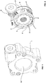
- Figure 1 shows a lockable overrunning clutch used for illustration purposes in an external view.
- the overrunning clutch can, for example, be fixed to an axle drive unit of a motor vehicle via the housing and used as a backstop, via which a sun, a planetary gear set or a ring gear of a 2-speed planetary gear can be blocked in one direction of rotation and another can be released in another direction of rotation.
- the housing functions as a first coupling element 1, which - depending on whether the overrunning clutch is in a freewheeling position released by a locking element or in an engaged position - allows the rotation of a second coupling element in a freewheeling direction or if there is a torsional stress opposite to the freewheeling direction ( Direction of rotation of the load).
- the first coupling member 1 is an outer, standing coupling member, by means of which a reverse rotation of a second coupling member 2 in a direction of rotation opposite to a freewheeling direction can be prevented.
- the first coupling member can also be a rotatably mounted coupling member and / or an inner coupling member while maintaining the functions of the overrunning clutch described below. Use of a clutch designed according to the exemplary embodiments as an overrunning clutch is therefore also conceivable.
- Figure 2 grants a view of the inner workings of the in Figure 1 one-way clutch shown.
- the illustrated position of the overrunning clutch is an engagement position.
- an axially displaceable intermediate member 3 is arranged between the outer, first coupling member 1 (corresponds to the coupling housing in Figure 1 , in Figure 2 omitted) and an inner, second coupling member 2, an axially displaceable intermediate member 3 is arranged.
- the intermediate member 3 is as formed externally and internally toothed ring and received in an annular space between the outer, first coupling member and the inner, second coupling member 2, which is created by the fact that the first coupling member engages over the second coupling member in the axial direction.
- the first coupling member is the outer coupling member which axially overlaps the inner, second coupling member 2.
- the intermediate member 3 has a helical toothing 4 'as the outer load toothing and an internal toothing 5' as the inner load toothing.
- the outer helical toothing 4 ' protrudes from one provided on the inner side of the outer coupling member 1, in particular also from Figure 3b and Figure 4c visible inner helical toothing 4 "over the entire length of the outer helical toothing 4 '.
- the outer helical toothing 4' extends in the embodiment illustrated by the figures over the entire axial width of the intermediate member 3.
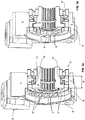
- Figure 2 , Figure 3a and Figure 4a The engagement position shown in engagement with an external toothing 5 "provided on the second coupling member 2.
- the gear engagement pairings 4 '/ 4 "and 5' / 5" described form the load gear pairings via which torque is transmitted between the coupling members 1, 2 with the interposition of the intermediate member when the overrunning clutch is used as intended.
- These load gear pairings are distributed axially in the engagement position over a gear width B, which consists of Figure 3a can be seen.
- the toothing width B is defined by the axial distance from the outer toothing planes perpendicular to the axis of rotation, in which on the inside and / or outside of the intermediate link effective load gear pairings are just still effective.
- a load toothing 4 'arranged on the intermediate member and in engagement with the first coupling member 1 extends over the entire width of the intermediate member 3 and the load toothing 5' engaging with the second coupling member 2 does not axially overlap the load gearing 4 ′ extends out, the gearing width B corresponds at the same time to the axial width of the intermediate member 3.
- the intermediate member 3 is arranged axially displaceably between the inner coupling member 2 and the outer coupling member 1 and, under the action of the helical gear pairing 4 '/ 4 ", can be extracted from the in Figure 2 and Figure 3a engagement position shown axially in the in Figure 3b shown free-wheeling position are shifted. While in Figure 3a the intermediate member 3 and the inner coupling member 2 are engaged in an engagement position for load transmission via the gear pairing 5 '/ 5 "and the intermediate member 3 is supported with its axially outer surface pointing to the right against the roller bearing 31, the intermediate member 3 is in the in Figure 3b position shown shifted to the left while disengaging from the inner coupling member 2.
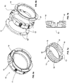
- a locking ring 6 functioning as a locking member was initially used from the in Figure 2 and Figure 3a blocking position shown, which is also shown in Figure 4a is shown in the in Figure 3b and Figure 4b Released position shown rotated relative to the first coupling member 1.
- a locking member is not absolutely necessary for the function of the clutch as a mere overrunning clutch, which allows free rotation in a freewheeling direction and a load transfer when a rotational stress is opposite to the freewheeling direction.
- it offers the possibility of blocking the clutch in the engaged position and thus, when the blocking element is in the blocking position, also to enable load transfer in the freewheeling direction of rotation, in that the blocking element prevents the intermediate element from being able to assume the freewheeling position.
- control pawls 9 which also function as synchronization pawls, on the intermediate member 3 within the toothing width B and radially on the inside of the overlap, in which the outer, first coupling member 1 and the inner, second coupling member 2 overlap to form an annular space overlaps, are arranged.
- the control pawls 9 are arranged in two diametrically opposite pocket-like openings in the intermediate member 3 ( Figure 2 and Figure 4c ) and received in the intermediate member 3 such that they can pivot freely and are supported radially on the outside with their side facing away from the intermediate member against the first coupling member 1.
- An additional storage element interacting with the control pawls is not provided.
- control pawls 9 on bearing pins that are supported on the side of the control pawls on the intermediate member and engage in the control pawl are pivotably mounted.
- control pawls shown in the figures and their diametrically opposite arrangement, which advantageously loads the intermediate ring symmetrically in the circumferential direction, has proven to be an advantageous embodiment.
- a different number of control pawls can also be provided (one or more than two) and a different arrangement can be selected.
- control pawls 9 are in engagement with a control member designed as a friction ring 12 via a control arm 11 offset axially relative to the control pawls 9.
- the friction ring 12 is in frictional contact with the inner coupling member 2 and with the inner ring of the bearing 31, but when the inner coupling member 2 and intermediate ring 3 rotate relative to each other, the control arm 11 is connected to the intermediate member 3 on the one hand and to the friction ring 12 on the other cooperates positively, prevented from rotating with the inner coupling member 2 and the inner ring of the bearing 30 that rotates with it.
- the control pawls 9 are either pushed into an open position in which the free ends of the control pawls 9 are pivoted away from the first coupling member 2 in the radial direction and are beyond the reach of the inner coupling member 2 provided external toothing 5 ".
- control pawls 9 are pushed into an engagement position in which the free ends of the control pawls 9 are urged radially inward in the direction of the first coupling member 2 and thereby come into contact with the external toothing 5".
- the control pawls 9 With a relative rotation of the inner coupling member 2 with respect to the intermediate ring 3 in the freewheeling direction of rotation F ( Figure 4b, Figure 5b ) the control pawls 9 are thus permanently pushed outwardly out of engagement with the toothing 5 ′′ provided on the inner coupling member 2 into the open position.
- control pawls with a control member that actuates the control pawls depending on the relative direction of rotation between the intermediate member and a coupling member has the advantage that the control pawls behave noiselessly, unlike control pawls that are permanently employed against control stops via a spring element.
- the toothing used as a load toothing on a coupling element is also used as a control stop, which represents a significant structural simplification, since this eliminates the need for the control toothing that is otherwise to be provided in addition to a load toothing and forming control stops.
- the overrunning clutch is in the in Figure 3a engagement position shown and the inner coupling member 2 is acted upon by force in the load direction of rotation M, the torque is transmitted from the inner coupling member 2 to the intermediate ring.
- This is in engagement with the outer coupling member 1 via the screw tooth pairing 4 '/ 4 "and is in Figure 3a pushed to the right against the inner ring of the bearing 31 and over this is supported on the assembly with which the outer coupling member 1, which is formed by the coupling housing, is firmly connected.
- the inner coupling member 2 is accordingly in a rotationally fixed, form-fitting connection with the outer coupling member 1 via the intermediate member. Due to the design of the form fit by means of highly resilient load gears, the clutch has a very high torque transmission potential despite its compactness.
- the inner clutch 2 also urges the friction ring 12 in the freewheeling direction F due to the friction force Via the entrainment projection formed by a control edge 10 of the recess 13, which is in contact with the control arms 11, an actuating force is exerted on the control arms 11 and thus an actuating torque initiated by friction on the control pawl 9 and in this way continuously pushes it into the open position ( Figure 4b, Figure 5b ).
- the inner coupling member 2 When the load direction changes again from the freewheeling direction F to the opposite load direction (load rotation direction M), the inner coupling member 2 initially rotates a small angular amount in the direction of rotation M, which results in a change in the effective direction of the actuating force between the friction ring 12 and the control arm 11 .
- the geometrical dimensions and the positioning of the control pawls 9 on the intermediate link are matched to the gear pairing 5 ', 5 "or synchronized with them, that when the control pawls 9 with the gear 5" come into contact with the coupling member 2, the toothing 5 'provided on the intermediate member can move laterally into the toothing 5 "provided on the coupling member 2 (Tooth in tooth gap).
- the control pawls 9 and the load gearing 5 ′′ thus also have a synchronization function.
- control part designed as a friction ring 12 is shown in detail for illustrative purposes Figure 6a and Figure 6b shown in a relaxed position.
- the friction ring 12 has a number corresponding to the number of control pawls or control arms and recesses 13 that are positioned accordingly on the intermediate member and into which the control arms 11 cooperating with the control pawls 9 can engage and are formed by the control edges 10 that are connected to the control arm 11 come into contact in order to be able to transmit the actuating forces exerted by the friction ring to the control arm 11.
- different types of projections or other means that enable the friction ring 12 to come into contact with the control arm 11 or directly against a control pawl 9 can also be provided.
- friction members 14 which act in the axial direction and extend over at least a partial section of the circumference are provided, which are assigned to a carrier ring 15. Friction members 14 and carrier ring 15 engage with one another via corresponding locking means 16 'and 16 "in such a way that the friction members are at least to a small extent axially displaceable with respect to carrier ring 15, but nonetheless secured against rotation with respect to carrier ring 15.
- carrier ring 15 In carrier ring 15 are receptacles for Pre-tensioning elements 17, preferably in the form of the spiral springs shown in the figures, are provided, by means of which the friction members 14 are urged away from the carrier ring 15 in the axial direction.
- the preloading elements 17 exert an actuating force by which the friction members 14 are positioned with their lateral outer surfaces against the boundary surfaces laterally bounding the annular gap.
- FIG. 7a and Figure 7b Show an alternative embodiment of a friction ring 12 Figure 7a and Figure 7b .
- the friction ring 12 is compressed in the axial direction when inserted into an annular gap laterally bounded by two boundary surfaces, the bending webs as pretensioning elements exert a restoring force through which the friction ring 12 with its outer surfaces formed by the side arms 19 is positioned against the boundary surfaces laterally bounding the annular gap will.
- This configuration also forms recesses 13 forming control edges 10.
- the frictional torque that the friction ring experiences when it is held stationary in this with a rotating annular gap can be easily adjusted via the design of preloading elements, in the exemplary embodiments shown thus via the springs or the flexural webs and side arms.
- the annular gap is formed between the inner ring of the bearing 31 and the lateral surfaces of the load toothing 5 ′′ provided on the coupling member 2, facing it.
- the arrangements or the assignments of the individual functional elements of the overrunning clutch in particular the arrangement or assignment of the screw teeth, the control pawl, the control part, the control stops and the locking member with its locking elements on the first coupling member, the second Coupling member or the intermediate ring, as well as the questions as to which of the two coupling members is arranged in the overlap area on the inside or outside of the respective other coupling member, whether the outer or inner coupling member is rotationally driven or only has a support function and which of the toothing types is radially outside or radially are provided on the inside of the functional parts, for maintaining the basic function of the overrunning clutch described and for the structural design described as advantageous in the context of the invention are not mandatory and do not necessarily have to be provided as shown in the figures.
- the overrunning clutch can be designed as a backstop.
- the overrunning clutch can, however, also be designed as an overrunning clutch in which one coupling part drives the other in a load transmission direction in rotation and is able to overtake in a freewheeling direction.
Landscapes
- Engineering & Computer Science (AREA)
- General Engineering & Computer Science (AREA)
- Mechanical Engineering (AREA)
- Mechanical Operated Clutches (AREA)
- Arrangement Of Transmissions (AREA)
Claims (15)
- Embrayage à roue libre comportant un premier élément d'embrayage (1), un second élément d'embrayage (2) et un élément intermédiaire (3) qui interagit avec le premier élément d'embrayage (1) et le second élément d'embrayage (2) et qui est capable de prendre une position de roue libre ou une position embrayée en fonction de la direction de la contrainte de rotation de l'embrayage à roue libre, un changement entre la position de roue libre et la position embrayée étant effectué par un déplacement axial de l'élément intermédiaire (3), et il est prévu au moins un mécanisme de commande qui, au moyen d'un élément de commande (9), déclenche le déplacement axial de l'organe intermédiaire (3) de la position de roue libre à la position embrayée, caractérisé en ce que le premier élément d'embrayage (1) s'engage axialement sur le deuxième élément d'embrayage (2) dans la position d'enclenchement en formant une largeur de denture effective (B), et l'élément de commande (9) est disposé au moins partiellement à l'intérieur de la largeur de denture (B) sur l'élément intermédiaire (3).
- Embrayage à roue libre selon la revendication 1 ou selon le terme générique de la revendication 1, caractérisé en ce que l'élément de commande (9) est disposé sur l'élément intermédiaire et, en position de roue libre, vient en contact avec une denture de charge prévue sur le premier élément d'embrayage (1) ou sur le deuxième élément d'embrayage (2) afin d'initier le déplacement axial de l' élément intermédiaire dans la position embrayée (3) lorsque la contrainte de rotation passe du sens de rotation de roue libre au sens de rotation de charge.
- Embrayage à roue libre selon la revendication 1 ou la revendication 2, caractérisé en ce qu'un organe de commande (12) disposé sur le premier élément d'embrayage (1) ou sur le second élément d'embrayage (2) et coopérant avec l'élément de commande (9) pour initier le déplacement axial de l'élément intermédiaire (3) est disposé radialement à l'intérieur du chevauchement.
- Embrayage à roue libre selon l'une des revendications précédentes, caractérisé en ce que l'élément intermédiaire (3) est annulaire et présente une surface annulaire extérieure pourvue au moins partiellement d'une denture de charge extérieure (4') et une surface annulaire intérieure pourvue au moins partiellement d'une denture de charge intérieure (5'), la denture de charge extérieure (4') recouvrant au moins partiellement la denture de charge intérieure (5') axialement.
- Embrayage à roue libre selon la revendication précédente, caractérisé en ce que la surface annulaire extérieure est pourvue de la denture de charge extérieure (4') sur toute la largeur axiale, tandis que la surface annulaire intérieure n'est pourvue d'une denture de charge intérieure (5') que dans une section partielle.
- Embrayage à crabots selon l'une quelconque des revendications précédentes, caractérisé en ce que l'élément intermédiaire (3) comporte des dentures de vis (5') sur une surface annulaire intérieure ou sur une surface annulaire extérieure, les dentures de vis (5') sur l'élément intermédiaire (3) s'engageant avec des dentures de vis correspondantes (5") sur l'un des éléments d'embrayage.
- Embrayage à roue libre selon l'une des revendications précédentes, caractérisé en ce que le mécanisme de commande est agencé de telle sorte qu'il n'autorise le déplacement axial de l'organe intermédiaire (3) de la position de roue libre à la position embrayée que dans des positions angulaires définies assurant le passage de l'élément intermédiaire (3) en position embrayée.
- Embrayage à roue libre selon l'une des revendications précédentes, caractérisé en ce que le mécanisme de commande comprend un organe de commande (12) qui, en fonction du sens d'une rotation relative entre les éléments d'embrayage (1, 2), sollicite en permanence l'élément de commande (9) dans une position ouverte lorsque l'embrayage à roue libre est sollicité dans le sens de rotation de la roue libre F, dans lequel l'organe de commande (12) est en contact de friction avec un élément d'embrayage (2) et, lorsque les éléments d'embrayage (1, 2) tournent l'un par rapport à l'autre, est appliquée avec une force de friction directement ou indirectement contre l'élément de commande (9).
- Embrayage à roue libre selon la revendication 8, caractérisé en ce que l'organe de commande (12) est conçue comme un anneau de friction en contact de friction avec un élément d'embrayage (2).
- Embrayage à roue libre selon l'une des revendications précédentes, caractérisé en ce qu'un ou plusieurs évidements ou ouvertures radiaux en forme de poche sont réalisés dans l'élément intermédiaire (3) pour recevoir l'élément de commande (9).
- Embrayage à roue libre selon l'une quelconque des revendications précédentes, caractérisé en ce qu'il est prévu un élément de blocage (6) qui bloque le déplacement axial de l'élément intermédiaire (3) de la position embrayée à la position de roue libre lorsque l'élément de blocage (6) est dans une position de blocage, et libère le déplacement axial de l'élément intermédiaire (3) de la position embrayée à la position de roue libre lorsqu'il est dans une position de libération.
- Embrayage à roue libre selon la revendication précédente, caractérisé en ce que l'élément de blocage (6) présente une denture de blocage (7) correspondant à une denture de vis (4") d'un élément d'embrayage (1) ou une denture de blocage (7) correspondant à la denture de charge (5") d'un élément d'embrayage (2), qui chevauche la denture de vis (4") ou la denture de charge (5") prévue sur l'élément d'embrayage respectif, à laquelle correspond la denture de blocage (7), lorsque l'élément de blocage (6) est dans la position de libération, de sorte que l'élément intermédiaire (3) peut se déplacer axialement dans l'élément de blocage (6) afin de prendre la position de roue libre.
- Embrayage à roue libre selon l'une des trois revendications précédentes, caractérisé en ce que l'élément de blocage (6) est conçu comme un élément de blocage commutable de l'extérieur, qui passe, par un actionnement externe, de la position de blocage à la position de libération et/ou de la position de libération à la position de blocage, l'élément de blocage (6) étant monostable et la position de blocage ou la position de libération formant une position de base que l'élément de blocage (6) prend automatiquement lorsqu'il n'est pas sollicité par le système d'actionnement.
- Unité d'entraînement d'essieu entraînée par un moteur électrique d'un véhicule automobile avec une boîte de vitesses planétaire à 2 vitesses, par l'intermédiaire de laquelle différents étages de transmission sont réalisés entre un entraînement par moteur électrique et les roues motrices entraînées par l'unité d'entraînement d'essieu, dans laquelle, en utilisant un embrayage à roue libre selon l'une des revendications précédentes dans l'unité d'entraînement d'essieu, l'embrayage à roue libre est utilisé pour réaliser l'étage de transmission de la boîte de vitesses planétaire à 2 vitesses en bloquant ou en libérant la rotation d'un soleil et/ou d'un train planétaire et/ou d'une couronne dentée.
- Unité d'entraînement d'essieu entraînée par un moteur électrique selon la revendication précédente, caractérisée en ce que l'embrayage à roue libre est un embrayage à roue libre qui peut être bloqué au moyen d'un élément de blocage (6) et qui est utilisé comme antidévireur, et une opération de marche arrière et/ou de récupération est rendue possible par l'embrayage à roue libre au moyen de l'élément de blocage.
Priority Applications (1)
| Application Number | Priority Date | Filing Date | Title |
|---|---|---|---|
| PL17781005T PL3682131T3 (pl) | 2017-09-12 | 2017-09-12 | Sprzęgło jednokierunkowe |
Applications Claiming Priority (1)
| Application Number | Priority Date | Filing Date | Title |
|---|---|---|---|
| PCT/EP2017/072876 WO2019052635A1 (fr) | 2017-09-12 | 2017-09-12 | Embrayage à roue libre |
Publications (2)
| Publication Number | Publication Date |
|---|---|
| EP3682131A1 EP3682131A1 (fr) | 2020-07-22 |
| EP3682131B1 true EP3682131B1 (fr) | 2021-11-17 |
Family
ID=60043139
Family Applications (1)
| Application Number | Title | Priority Date | Filing Date |
|---|---|---|---|
| EP17781005.8A Active EP3682131B1 (fr) | 2017-09-12 | 2017-09-12 | Embrayage à roue libre |
Country Status (6)
| Country | Link |
|---|---|
| US (1) | US11187283B2 (fr) |
| EP (1) | EP3682131B1 (fr) |
| JP (1) | JP6932845B2 (fr) |
| CN (1) | CN111133213B (fr) |
| PL (1) | PL3682131T3 (fr) |
| WO (1) | WO2019052635A1 (fr) |
Families Citing this family (1)
| Publication number | Priority date | Publication date | Assignee | Title |
|---|---|---|---|---|
| CN109965733B (zh) * | 2019-04-01 | 2024-07-23 | 王晓东 | 一种改进的具有料渣收集功能的食品处理机 |
Family Cites Families (42)
| Publication number | Priority date | Publication date | Assignee | Title |
|---|---|---|---|---|
| US1396343A (en) | 1918-11-13 | 1921-11-08 | Mechano Gear Shift Co | Clutch |
| US1883966A (en) | 1930-09-20 | 1932-10-25 | Frank R Krause | Overrunning clutch |
| DE632395C (de) | 1933-05-19 | 1936-07-09 | Klein Schanzlin & Becker Akt G | Selbsttaetige Schaltkupplung fuer Getriebe, insbesondere Fluessigkeitsgetriebe |
| DE763479C (de) | 1934-03-24 | 1952-01-31 | Norton Legge | Synchronisierungs- und Freilaufkupplung, insbesondere fuer Kraftfahrzeuge |
| US2323353A (en) | 1940-12-18 | 1943-07-06 | William H Plog | One-way clutch |
| US2574004A (en) | 1949-06-23 | 1951-11-06 | Dana Corp | Balking ring clutch |
| GB1409810A (en) | 1972-10-31 | 1975-10-15 | Sss Patents Ltd | Synchronous self-shifting clutch |
| US4126214A (en) | 1976-11-23 | 1978-11-21 | Kiss Laszlo J | Positive one-way clutch system |
| GB2034420B (en) | 1978-11-23 | 1982-10-13 | Itt Creed | Freewheel clutch |
| JPS5822528U (ja) * | 1981-08-05 | 1983-02-12 | 三菱農機株式会社 | 一方向クラツチ |
| DE3535264A1 (de) | 1985-10-03 | 1987-04-09 | Walterscheid Gmbh Jean | In abtriebsrichtung abschaltbarer freilauf |
| JP3649793B2 (ja) | 1994-12-28 | 2005-05-18 | Ntn株式会社 | フリーホイールクラッチ |
| JP3501312B2 (ja) | 1995-05-26 | 2004-03-02 | 株式会社デンソー | 一方向性クラッチ |
| EP1066477B1 (fr) * | 1998-03-02 | 2004-10-13 | BorgWarner Inc. | Embrayage a roue libre a rochets |
| US6155394A (en) | 1999-03-22 | 2000-12-05 | Shook; William B. | Bicycle coasting mechanism |
| US6193038B1 (en) * | 1999-08-18 | 2001-02-27 | Means Industries, Inc. | One-way clutch and method for making same |
| DE10019989A1 (de) | 2000-04-22 | 2001-10-25 | Sram De Gmbh | Freilaufkupplung mit zwangsgesteuerter Sperrklinke |
| KR100360642B1 (ko) | 2000-08-22 | 2002-11-13 | 현대자동차주식회사 | 수동 변속기용 동기장치 |
| SE518727C2 (sv) | 2001-12-17 | 2002-11-12 | Scania Cv Abp | Byggsystem för synkroniseringsanordningar till en växellåda |
| CN2602214Y (zh) | 2003-01-23 | 2004-02-04 | 张少棣 | 传动轴离合器 |
| US6854577B2 (en) * | 2003-04-29 | 2005-02-15 | Means Industries, Inc. | Sound dampened one-way clutch |
| DE102004040810A1 (de) | 2004-08-24 | 2006-03-02 | Ina-Schaeffler Kg | Vorrichtung zur Dämpfung von Drehschwingungen |
| EP1724487B1 (fr) | 2005-05-19 | 2009-08-12 | LuK Lamellen und Kupplungsbau Beteiligungs KG | Roue libre |
| CA2620887A1 (fr) * | 2005-09-02 | 2007-03-08 | Gkn Sinter Metals, Inc. | Roue libre |
| US8210331B2 (en) | 2006-03-06 | 2012-07-03 | Hossein Estahbanati Keshtkar | One-way pawl clutch with backlash reduction means and without biasing means |
| US8491439B2 (en) * | 2007-02-06 | 2013-07-23 | Ford Global Technologies, Llc | Selectively controlled rocker one-way clutch |
| US8056690B2 (en) * | 2008-02-14 | 2011-11-15 | GM Global Technology Operations LLC | Rotary-type selectable one-way clutch |
| DE102008017681A1 (de) | 2008-04-08 | 2009-10-15 | Schaeffler Kg | Freilaufkupplung |
| US8286772B2 (en) * | 2009-04-01 | 2012-10-16 | Means Industries, Inc. | Controllable coupling assembly and overrunning coupling and control assembly utilizing same |
| JP5885214B2 (ja) * | 2010-12-10 | 2016-03-15 | ミーンズ インダストリーズ,インク. | 電気機械駆動式連結器および制御アセンブリ |
| US8522943B2 (en) * | 2011-03-07 | 2013-09-03 | Gm Global Technology Operation Llc | Electromagnetically controlled clutch assembly and control method for the same |
| DE102012001836B4 (de) * | 2012-01-31 | 2022-10-13 | Hoerbiger Antriebstechnik Holding Gmbh | Schalttransmitter eines sperrsynchronisierten Schaltgetriebes |
| DE102012222669A1 (de) | 2012-12-10 | 2014-06-12 | Robert Bosch Gmbh | Freilaufkupplung |
| JP6013236B2 (ja) | 2013-03-07 | 2016-10-25 | 本田技研工業株式会社 | シンクロ装置 |
| JP5849070B2 (ja) | 2013-06-24 | 2016-01-27 | 京セラドキュメントソリューションズ株式会社 | ワンウェイクラッチ、およびこれを備えた駆動装置 |
| DE112014003734A5 (de) | 2013-08-15 | 2016-05-19 | Schaeffler Technologies AG & Co. KG | Freilauf |
| DE112015001203T5 (de) | 2014-04-21 | 2016-12-08 | Borgwarner Inc. | Axial wirkendes Stellglied für multimodales Kupplungsmodul |
| WO2017041803A1 (fr) | 2015-09-10 | 2017-03-16 | Schaeffler Technologies AG & Co. KG | Élément de pression d'une boîte de vitesses de véhicule et unité de syncrhonisation |
| KR101795163B1 (ko) | 2015-11-04 | 2017-11-08 | 현대자동차주식회사 | 차량용 클러치 |
| US10247261B2 (en) | 2016-03-01 | 2019-04-02 | Borgwarner Inc. | Clutch actuation using differential pressure |
| US20170023073A1 (en) | 2016-10-10 | 2017-01-26 | Caterpillar Inc. | One-way clutch |
| US10920858B2 (en) | 2016-11-29 | 2021-02-16 | Gkn Automotive Ltd. | Shiftable two-speed transmission suitable for edrive |
-
2017
- 2017-09-12 WO PCT/EP2017/072876 patent/WO2019052635A1/fr not_active Ceased
- 2017-09-12 JP JP2020514923A patent/JP6932845B2/ja active Active
- 2017-09-12 PL PL17781005T patent/PL3682131T3/pl unknown
- 2017-09-12 EP EP17781005.8A patent/EP3682131B1/fr active Active
- 2017-09-12 US US16/645,645 patent/US11187283B2/en not_active Expired - Fee Related
- 2017-09-12 CN CN201780094832.6A patent/CN111133213B/zh active Active
Also Published As
| Publication number | Publication date |
|---|---|
| JP6932845B2 (ja) | 2021-09-08 |
| CN111133213A (zh) | 2020-05-08 |
| US11187283B2 (en) | 2021-11-30 |
| CN111133213B (zh) | 2022-02-18 |
| US20200277998A1 (en) | 2020-09-03 |
| PL3682131T3 (pl) | 2022-03-28 |
| JP2020533539A (ja) | 2020-11-19 |
| EP3682131A1 (fr) | 2020-07-22 |
| WO2019052635A1 (fr) | 2019-03-21 |
Similar Documents
| Publication | Publication Date | Title |
|---|---|---|
| EP2235391B1 (fr) | Élément amplificateur de force | |
| EP2829774A1 (fr) | Système de frein de stationnement et boîte de vitesses de véhicule automobile | |
| DE10196484T5 (de) | Vorrichtung zum Sperren der Zahnräder einer Kraftübertragung | |
| DE102011108977B4 (de) | Aktuator, insbesondere für einenFahrzeugsitz | |
| EP3328683B1 (fr) | Dispositif de réglage de siège avec verrouillage supplémentaire | |
| EP2748028B1 (fr) | Ferrure de réglage pourvue d'un système de blocage axial destiné à sécuriser le fonctionnement | |
| EP3682132B1 (fr) | Embrayage à roue libre présentant une force de réglage induite par frottement | |
| EP3313690B1 (fr) | Dispositif de réglage de siège | |
| DE102008028086A1 (de) | Ablaufsicherung sowie Verstellbeschlag | |
| DE102015120818B4 (de) | Getriebe mit schaltbarem Planetensatz sowie Freilaufkupplung für ein elektrisch antreibbares Kraftfahrzeug | |
| DE102016108701B3 (de) | Schaltvorrichtung für ein Kraftfahrzeuggetriebe | |
| EP3682131B1 (fr) | Embrayage à roue libre | |
| EP3701162A1 (fr) | Dispositif et procédé de synchronisation | |
| DE102012011180A9 (de) | Kupplungseinrichtung | |
| EP3908765B1 (fr) | Arrangement actionneur pour un arrangement d'accouplement pour une chaîne cinématique d'un véhicule automobile | |
| DE102015121705A1 (de) | Kupplungsanordnung, insbesondere zum optionalen Verbinden eines Luftverdichters mit einer Antriebseinrichtung | |
| EP2616703B1 (fr) | Unité de synchronisation pour un embrayage principal à complémentarité de forme | |
| DE102023200202A1 (de) | Kupplungsanordnung und Antriebsstrang mit Kupplungsanordnung | |
| DE202008015024U1 (de) | Drehrichtungsabhängig kuppelbarer Freilauf | |
| DE102019118319A1 (de) | Nachstelleinheit für ein axial betätigbares Kupplungssystem, Betätigungsvorrichtung sowie Verfahren zum Betrieb einer Betätigungsvorrichtung | |
| DE10200483A1 (de) | Vorrichtung zum schrittweisen Drehantrieb eines Drehorgans | |
| DE202009016144U1 (de) | Sperrkeilsynchronisationsbaugruppe sowie Schaltgetriebe mit einer solchen Sperrkeilsynchronisationsbaugruppe | |
| WO2013104523A1 (fr) | Mécanisme pas à pas pour dispositifs de réglage de véhicules automobiles | |
| DE102010036275A1 (de) | Transmitter sowie Synchronisierungsbaugruppe mit einem Transmitter |
Legal Events
| Date | Code | Title | Description |
|---|---|---|---|
| STAA | Information on the status of an ep patent application or granted ep patent |
Free format text: STATUS: UNKNOWN |
|
| STAA | Information on the status of an ep patent application or granted ep patent |
Free format text: STATUS: THE INTERNATIONAL PUBLICATION HAS BEEN MADE |
|
| PUAI | Public reference made under article 153(3) epc to a published international application that has entered the european phase |
Free format text: ORIGINAL CODE: 0009012 |
|
| STAA | Information on the status of an ep patent application or granted ep patent |
Free format text: STATUS: REQUEST FOR EXAMINATION WAS MADE |
|
| 17P | Request for examination filed |
Effective date: 20200408 |
|
| AK | Designated contracting states |
Kind code of ref document: A1 Designated state(s): AL AT BE BG CH CY CZ DE DK EE ES FI FR GB GR HR HU IE IS IT LI LT LU LV MC MK MT NL NO PL PT RO RS SE SI SK SM TR |
|
| AX | Request for extension of the european patent |
Extension state: BA ME |
|
| DAV | Request for validation of the european patent (deleted) | ||
| DAX | Request for extension of the european patent (deleted) | ||
| GRAP | Despatch of communication of intention to grant a patent |
Free format text: ORIGINAL CODE: EPIDOSNIGR1 |
|
| STAA | Information on the status of an ep patent application or granted ep patent |
Free format text: STATUS: GRANT OF PATENT IS INTENDED |
|
| INTG | Intention to grant announced |
Effective date: 20210527 |
|
| GRAS | Grant fee paid |
Free format text: ORIGINAL CODE: EPIDOSNIGR3 |
|
| GRAA | (expected) grant |
Free format text: ORIGINAL CODE: 0009210 |
|
| STAA | Information on the status of an ep patent application or granted ep patent |
Free format text: STATUS: THE PATENT HAS BEEN GRANTED |
|
| AK | Designated contracting states |
Kind code of ref document: B1 Designated state(s): AL AT BE BG CH CY CZ DE DK EE ES FI FR GB GR HR HU IE IS IT LI LT LU LV MC MK MT NL NO PL PT RO RS SE SI SK SM TR |
|
| REG | Reference to a national code |
Ref country code: GB Ref legal event code: FG4D Free format text: NOT ENGLISH |
|
| REG | Reference to a national code |
Ref country code: IE Ref legal event code: FG4D Free format text: LANGUAGE OF EP DOCUMENT: GERMAN |
|
| REG | Reference to a national code |
Ref country code: DE Ref legal event code: R096 Ref document number: 502017012057 Country of ref document: DE |
|
| REG | Reference to a national code |
Ref country code: AT Ref legal event code: REF Ref document number: 1448298 Country of ref document: AT Kind code of ref document: T Effective date: 20211215 |
|
| REG | Reference to a national code |
Ref country code: LT Ref legal event code: MG9D |
|
| REG | Reference to a national code |
Ref country code: NL Ref legal event code: MP Effective date: 20211117 |
|
| PG25 | Lapsed in a contracting state [announced via postgrant information from national office to epo] |
Ref country code: RS Free format text: LAPSE BECAUSE OF FAILURE TO SUBMIT A TRANSLATION OF THE DESCRIPTION OR TO PAY THE FEE WITHIN THE PRESCRIBED TIME-LIMIT Effective date: 20211117 Ref country code: LT Free format text: LAPSE BECAUSE OF FAILURE TO SUBMIT A TRANSLATION OF THE DESCRIPTION OR TO PAY THE FEE WITHIN THE PRESCRIBED TIME-LIMIT Effective date: 20211117 Ref country code: FI Free format text: LAPSE BECAUSE OF FAILURE TO SUBMIT A TRANSLATION OF THE DESCRIPTION OR TO PAY THE FEE WITHIN THE PRESCRIBED TIME-LIMIT Effective date: 20211117 Ref country code: BG Free format text: LAPSE BECAUSE OF FAILURE TO SUBMIT A TRANSLATION OF THE DESCRIPTION OR TO PAY THE FEE WITHIN THE PRESCRIBED TIME-LIMIT Effective date: 20220217 |
|
| PG25 | Lapsed in a contracting state [announced via postgrant information from national office to epo] |
Ref country code: IS Free format text: LAPSE BECAUSE OF FAILURE TO SUBMIT A TRANSLATION OF THE DESCRIPTION OR TO PAY THE FEE WITHIN THE PRESCRIBED TIME-LIMIT Effective date: 20220317 Ref country code: SE Free format text: LAPSE BECAUSE OF FAILURE TO SUBMIT A TRANSLATION OF THE DESCRIPTION OR TO PAY THE FEE WITHIN THE PRESCRIBED TIME-LIMIT Effective date: 20211117 Ref country code: PT Free format text: LAPSE BECAUSE OF FAILURE TO SUBMIT A TRANSLATION OF THE DESCRIPTION OR TO PAY THE FEE WITHIN THE PRESCRIBED TIME-LIMIT Effective date: 20220317 Ref country code: NO Free format text: LAPSE BECAUSE OF FAILURE TO SUBMIT A TRANSLATION OF THE DESCRIPTION OR TO PAY THE FEE WITHIN THE PRESCRIBED TIME-LIMIT Effective date: 20220217 Ref country code: NL Free format text: LAPSE BECAUSE OF FAILURE TO SUBMIT A TRANSLATION OF THE DESCRIPTION OR TO PAY THE FEE WITHIN THE PRESCRIBED TIME-LIMIT Effective date: 20211117 Ref country code: LV Free format text: LAPSE BECAUSE OF FAILURE TO SUBMIT A TRANSLATION OF THE DESCRIPTION OR TO PAY THE FEE WITHIN THE PRESCRIBED TIME-LIMIT Effective date: 20211117 Ref country code: HR Free format text: LAPSE BECAUSE OF FAILURE TO SUBMIT A TRANSLATION OF THE DESCRIPTION OR TO PAY THE FEE WITHIN THE PRESCRIBED TIME-LIMIT Effective date: 20211117 Ref country code: GR Free format text: LAPSE BECAUSE OF FAILURE TO SUBMIT A TRANSLATION OF THE DESCRIPTION OR TO PAY THE FEE WITHIN THE PRESCRIBED TIME-LIMIT Effective date: 20220218 Ref country code: ES Free format text: LAPSE BECAUSE OF FAILURE TO SUBMIT A TRANSLATION OF THE DESCRIPTION OR TO PAY THE FEE WITHIN THE PRESCRIBED TIME-LIMIT Effective date: 20211117 |
|
| PG25 | Lapsed in a contracting state [announced via postgrant information from national office to epo] |
Ref country code: SM Free format text: LAPSE BECAUSE OF FAILURE TO SUBMIT A TRANSLATION OF THE DESCRIPTION OR TO PAY THE FEE WITHIN THE PRESCRIBED TIME-LIMIT Effective date: 20211117 Ref country code: SK Free format text: LAPSE BECAUSE OF FAILURE TO SUBMIT A TRANSLATION OF THE DESCRIPTION OR TO PAY THE FEE WITHIN THE PRESCRIBED TIME-LIMIT Effective date: 20211117 Ref country code: RO Free format text: LAPSE BECAUSE OF FAILURE TO SUBMIT A TRANSLATION OF THE DESCRIPTION OR TO PAY THE FEE WITHIN THE PRESCRIBED TIME-LIMIT Effective date: 20211117 Ref country code: EE Free format text: LAPSE BECAUSE OF FAILURE TO SUBMIT A TRANSLATION OF THE DESCRIPTION OR TO PAY THE FEE WITHIN THE PRESCRIBED TIME-LIMIT Effective date: 20211117 Ref country code: DK Free format text: LAPSE BECAUSE OF FAILURE TO SUBMIT A TRANSLATION OF THE DESCRIPTION OR TO PAY THE FEE WITHIN THE PRESCRIBED TIME-LIMIT Effective date: 20211117 Ref country code: CZ Free format text: LAPSE BECAUSE OF FAILURE TO SUBMIT A TRANSLATION OF THE DESCRIPTION OR TO PAY THE FEE WITHIN THE PRESCRIBED TIME-LIMIT Effective date: 20211117 |
|
| REG | Reference to a national code |
Ref country code: DE Ref legal event code: R097 Ref document number: 502017012057 Country of ref document: DE |
|
| PLBE | No opposition filed within time limit |
Free format text: ORIGINAL CODE: 0009261 |
|
| STAA | Information on the status of an ep patent application or granted ep patent |
Free format text: STATUS: NO OPPOSITION FILED WITHIN TIME LIMIT |
|
| 26N | No opposition filed |
Effective date: 20220818 |
|
| PG25 | Lapsed in a contracting state [announced via postgrant information from national office to epo] |
Ref country code: AL Free format text: LAPSE BECAUSE OF FAILURE TO SUBMIT A TRANSLATION OF THE DESCRIPTION OR TO PAY THE FEE WITHIN THE PRESCRIBED TIME-LIMIT Effective date: 20211117 |
|
| PG25 | Lapsed in a contracting state [announced via postgrant information from national office to epo] |
Ref country code: SI Free format text: LAPSE BECAUSE OF FAILURE TO SUBMIT A TRANSLATION OF THE DESCRIPTION OR TO PAY THE FEE WITHIN THE PRESCRIBED TIME-LIMIT Effective date: 20211117 |
|
| PG25 | Lapsed in a contracting state [announced via postgrant information from national office to epo] |
Ref country code: MC Free format text: LAPSE BECAUSE OF FAILURE TO SUBMIT A TRANSLATION OF THE DESCRIPTION OR TO PAY THE FEE WITHIN THE PRESCRIBED TIME-LIMIT Effective date: 20211117 |
|
| REG | Reference to a national code |
Ref country code: CH Ref legal event code: PL |
|
| REG | Reference to a national code |
Ref country code: BE Ref legal event code: MM Effective date: 20220930 |
|
| PG25 | Lapsed in a contracting state [announced via postgrant information from national office to epo] |
Ref country code: IT Free format text: LAPSE BECAUSE OF FAILURE TO SUBMIT A TRANSLATION OF THE DESCRIPTION OR TO PAY THE FEE WITHIN THE PRESCRIBED TIME-LIMIT Effective date: 20211117 |
|
| PG25 | Lapsed in a contracting state [announced via postgrant information from national office to epo] |
Ref country code: LU Free format text: LAPSE BECAUSE OF NON-PAYMENT OF DUE FEES Effective date: 20220912 |
|
| PG25 | Lapsed in a contracting state [announced via postgrant information from national office to epo] |
Ref country code: LI Free format text: LAPSE BECAUSE OF NON-PAYMENT OF DUE FEES Effective date: 20220930 Ref country code: IE Free format text: LAPSE BECAUSE OF NON-PAYMENT OF DUE FEES Effective date: 20220912 Ref country code: CH Free format text: LAPSE BECAUSE OF NON-PAYMENT OF DUE FEES Effective date: 20220930 |
|
| PG25 | Lapsed in a contracting state [announced via postgrant information from national office to epo] |
Ref country code: BE Free format text: LAPSE BECAUSE OF NON-PAYMENT OF DUE FEES Effective date: 20220930 |
|
| PG25 | Lapsed in a contracting state [announced via postgrant information from national office to epo] |
Ref country code: CY Free format text: LAPSE BECAUSE OF FAILURE TO SUBMIT A TRANSLATION OF THE DESCRIPTION OR TO PAY THE FEE WITHIN THE PRESCRIBED TIME-LIMIT Effective date: 20211117 |
|
| PG25 | Lapsed in a contracting state [announced via postgrant information from national office to epo] |
Ref country code: MK Free format text: LAPSE BECAUSE OF FAILURE TO SUBMIT A TRANSLATION OF THE DESCRIPTION OR TO PAY THE FEE WITHIN THE PRESCRIBED TIME-LIMIT Effective date: 20211117 Ref country code: HU Free format text: LAPSE BECAUSE OF FAILURE TO SUBMIT A TRANSLATION OF THE DESCRIPTION OR TO PAY THE FEE WITHIN THE PRESCRIBED TIME-LIMIT; INVALID AB INITIO Effective date: 20170912 |
|
| PG25 | Lapsed in a contracting state [announced via postgrant information from national office to epo] |
Ref country code: TR Free format text: LAPSE BECAUSE OF FAILURE TO SUBMIT A TRANSLATION OF THE DESCRIPTION OR TO PAY THE FEE WITHIN THE PRESCRIBED TIME-LIMIT Effective date: 20211117 |
|
| PG25 | Lapsed in a contracting state [announced via postgrant information from national office to epo] |
Ref country code: MT Free format text: LAPSE BECAUSE OF FAILURE TO SUBMIT A TRANSLATION OF THE DESCRIPTION OR TO PAY THE FEE WITHIN THE PRESCRIBED TIME-LIMIT Effective date: 20211117 |
|
| PGFP | Annual fee paid to national office [announced via postgrant information from national office to epo] |
Ref country code: GB Payment date: 20240923 Year of fee payment: 8 |
|
| PGFP | Annual fee paid to national office [announced via postgrant information from national office to epo] |
Ref country code: FR Payment date: 20240924 Year of fee payment: 8 |
|
| PGFP | Annual fee paid to national office [announced via postgrant information from national office to epo] |
Ref country code: AT Payment date: 20240918 Year of fee payment: 8 |
|
| PGFP | Annual fee paid to national office [announced via postgrant information from national office to epo] |
Ref country code: PL Payment date: 20240830 Year of fee payment: 8 |
|
| PGFP | Annual fee paid to national office [announced via postgrant information from national office to epo] |
Ref country code: DE Payment date: 20250919 Year of fee payment: 9 |