EP3682992A1 - Vorrichtung zum bohren einer kanalisation - Google Patents
Vorrichtung zum bohren einer kanalisation Download PDFInfo
- Publication number
- EP3682992A1 EP3682992A1 EP20152517.7A EP20152517A EP3682992A1 EP 3682992 A1 EP3682992 A1 EP 3682992A1 EP 20152517 A EP20152517 A EP 20152517A EP 3682992 A1 EP3682992 A1 EP 3682992A1
- Authority
- EP
- European Patent Office
- Prior art keywords
- shaft
- cam
- drilling
- cam follower
- cutting tool
- Prior art date
- Legal status (The legal status is an assumption and is not a legal conclusion. Google has not performed a legal analysis and makes no representation as to the accuracy of the status listed.)
- Granted
Links
Images


Classifications
-
- F—MECHANICAL ENGINEERING; LIGHTING; HEATING; WEAPONS; BLASTING
- F16—ENGINEERING ELEMENTS AND UNITS; GENERAL MEASURES FOR PRODUCING AND MAINTAINING EFFECTIVE FUNCTIONING OF MACHINES OR INSTALLATIONS; THERMAL INSULATION IN GENERAL
- F16L—PIPES; JOINTS OR FITTINGS FOR PIPES; SUPPORTS FOR PIPES, CABLES OR PROTECTIVE TUBING; MEANS FOR THERMAL INSULATION IN GENERAL
- F16L41/00—Branching pipes; Joining pipes to walls
- F16L41/04—Tapping pipe walls, i.e. making connections through the walls of pipes while they are carrying fluids; Fittings therefor
- F16L41/06—Tapping pipe walls, i.e. making connections through the walls of pipes while they are carrying fluids; Fittings therefor making use of attaching means embracing the pipe
Definitions
- the invention relates to a drilling device suitable for drilling a pipe under load (or not) such as for example a pipe transporting water, as well as a method of drilling a pipe using such a drilling device.
- bypass collars which traditionally include a saddle equipped with a valve and a flange (flexible or rigid). Conventionally, this type of collar is mounted on a water pipe under load (or not), the flexible flange being deformed to surround the pipe, the saddle resting on an outer wall of the pipe.
- the field of the invention is more particularly that of piercing devices used to pierce the wall of the pipe in line with the tap, and through the tubing of the latter, once the bypass collar is in place.
- drilling devices specially configured for this use which comprise a connection part configured to be removably attached to a valve. of a bypass collar as well as a movable cutting tool with respect to said connection part, configured to pass through said valve while ensuring the drilling of the pipe.
- such a drilling device comprises a connection part which is fixed to the valve of the collar, in a rigid manner, as well as a tool-holder shaft, coupled to a cutting tool, intended to cross the valve to attack the pipeline.
- the tool-holder shaft is linked mechanically to the connection part by a screwing system.
- the document WO 99/32823 teaches such a drilling technique. Drilling of the pipe is obtained by setting the tool-holder shaft in rotation, manually or motorized. This rotation causes the joint rotation of the cutting tool and its advancement by a displacement dependent on the screw pitch of said screwing system. Such a drilling technique is widely used for drilling pipes under load.
- this drilling technique has the significant drawback that it imposes significant forces on the branch collar to which the drilling device is linked, which makes it necessary to oversize the branch collar and its flange in order to resist the mechanical stresses imposed by drilling operations.
- the drilling technique according to WO 99/32823 generates chips, which, because of their large size, are likely to degrade equipment such as water meters, when this waste is carried in the pipe, downstream by the circulating fluid or even the elements of 'blocking of the take-over valve for example.
- the drilling device provides significant progress in responding to this problem in that its structure makes it possible to dissociate the rotation applied by the shaft carrying the cutting tool, which is driven in rotation by motor means, on the one hand, from the force of thrust applied by the cutting tool which is provided only by elastic means, and in particular by a coil spring used in compression, on the other hand.
- the drilling force thus never exceeds that imposed by the elastic means: it is ensured that the drilling force does not alter the bypass collar on which the drilling device is attached.
- the releasable loading means are provided between the body and the first part.
- these means comprise clamping clamps secured to the first part, and coming to bear on a flange of the body to pull the first part by compressing a compression spring.
- these means comprise two cam levers, each articulated in a pivot relative to the body, and two rollers integral with the first part configured to cooperate with the cam.
- the compression of the coil spring and therefore the loading of the elastic means takes place by pulling the first part by implementing a force between the body and the first part, and in the direction opposite to the drilling direction, thanks to clamping clamps, or even thanks to cam / roller lever systems.
- clamping clamp or the pair of cam levers / rollers ensures a locking of the first part relative to the body in this position of compression of the elastic means, and while the shaft carrying the cutting tool is not still not in place in the valve, as well as in the components of the drilling device linked to this valve.
- the shaft and the cutting tool are not secured to the second part via the fixing means until after this compression step, by bringing the cutting tool into abutment against the pipe. Before proceeding with the drilling, it is still mandatory to release the clamp (or the cam system) so that the first part can transmit the thrust force of the elastic means to the tool resting against the pipe, and can be move when rotating the shaft and cutting tool while drilling.
- the drilling method requires a certain number of steps which cannot be reduced, and in particular successively a step of loading the elastic means, a step of fixing the shaft and the shaft. 'cutting tool, but also a step of releasing the elastic means so that the latter force the cutting tool against the pipe.
- this number of steps before drilling slows down the implementation during drilling, and can be the source of error for the operator.
- the problem to which the invention responds is first of all to propose a drilling device whose structure is configured for drilling under load of a pipe minimizing the forces on the pipe, like that of the document FR 2 984 780 , but the implementation of which is faster and easier than that of this prior art.
- Another object of the present invention is to provide such a piercing device which minimizes the risk of injury, by preventing empty charging of the elastic means of the piercing device.
- Another object of the present invention is to provide, at least according to one embodiment, such a drilling device minimizing the risks of pinching during the loading of the elastic means.
- the drilling device allows the compression of said elastic means, during the passage of the operating mechanism from the rest position to the working position, only when the cutting tool is in abutment against the pipe, and that the 'tree is attached to the second part.
- the first part may comprise a tube, coaxial with the shaft and traversed by said shaft, and in which the elastic means comprise a coil spring mounted around the tube, a projecting shoulder forming a seat for one end of the coil spring, l 'other end of the coil spring resting on a seat formed on the third part.
- the operating mechanism may include a control lever, pivotally articulated on the third part, as well as a cam and cam follower pair distributed between the body and the control lever, the cam follower being integral with the body and the cam integral with the base of the control lever, said operating mechanism being configured to take said rest position corresponding to a first relative position of the cam with respect to the cam follower, and said working position, obtained by pivoting of the control lever , and corresponding to a second relative position of the cam by relative to the cam follower, and wherein the cam comprises a cam track formed on a base portion of the control lever, the path being of variable radius with respect to the axis of rotation of the substantially decreasing radius control lever to the cam follower between the rest position and the working position of the operating mechanism to force the third part from the position remote from the connection part to the close position of the connection part.
- the cam track has two end stops for said cam follower; with a first stop for the cam follower in the rest position of the operating mechanism and a second stop for the cam follower in the operating position of the operating mechanism.
- the cam track may have a decreasing radius relative to the axis of rotation for the cam follower, immediately before the second limit switch, then a sharply increasing radius when said cam follower reaches said second limit switch, in order to constitute a stable position for the cam follower in the cam track in said operating position of the operating mechanism
- the cam and the cam follower of the maneuvering mechanism can advantageously be housed in a casing configured in order to prevent the risk of pinching between the cam and the cam follower.
- the cam follower may be a roller pivotally articulated on the body along a pivot axis substantially perpendicular to the shaft.
- the operating mechanism may comprise two said operating levers, each being associated with a pair of cam and cam follower distributed between the body and the control lever, said two pairs of cam and cam follower being distributed on either side. of the tree.
- the third part forms a housing partially receiving in its interior, the body at least partially at the opposite end of the connection part, as well as the first part and in which the third part comprises a guide surface, internal, configured to slide on an external reach of the body.
- the cutting tool is a cylindrical, tubular part having a discontinuous cutting edge with notches, the edge present being preferably covered with abrasive powder, such as diamond powder, and the wall of the cylindrical part having an opening intended to allow the flow of a liquid.
- abrasive powder such as diamond powder
- Such a tool generates cutting waste, of fine particle size, and so that this powder can be entrained in the pipe, and without risk of alteration of downstream equipment, such as water meters or even elements of blocking of the take-over valve, for example.
- the removable shaft attachment means comprises a bracing attachment system comprising a sheet metal provided with a passage opening for the shaft, and resilient means configured to bias the opening to ensure blocking by friction between the edges of the opening and said shaft.
- the invention and the variants thereof can allow, in general, to provide a drilling device suitable for drilling a pipe by minimizing the forces on the bypass collar like the document FR 2 984 780 but of simplified implementation compared to this prior art when drilling the pipe.
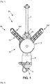
- the invention relates to a drilling device 1 suitable for drilling a pipe 2 under load (or not), comprising a connection part 3 configured to be removably attached to a valve 4 of a collar. bypass 5, as well as a cutting tool 6 movable relative to said connection part 3, configured to pass through said valve 4 to allow drilling of the pipe 2.
- Such a device is configured so as to allow drilling during which the drilling force (thrust force) and the advance of the cutting tool 6 are provided only by the elastic means 12.
- the drilling force thus never exceeds that imposed by the elastic means 12. It is ensured that the drilling operations do not alter the bypass collar to which the drilling device is attached.
- the stroke of the cutting tool is limited so as to prevent the cutting tool 6 from damaging the wall of the pipe opposite to that which has just been crossed by the cutting tool 6, at the end of the drilling .
- the first part 9 comes into contact with a stop formed on the body 8.
- the motor means may comprise a drill or screwdriver, in particular a commercial one.
- the motor means are coupled to the distal end 70 of the shaft 7 which may be of polygonal section, such as for example of square or hexagonal section.
- the motor means are locked in rotation, either by the hand of the user himself, or by a mechanical support (not shown) configured to accompany the movement of the shaft. In the event that the user blocks the rotation of the motor means, he exerts no force in the direction of the shaft, in the direction of thrust or in the opposite direction.
- the operating mechanism 15 is thus configured to ensure the compression of the elastic means 12 by the passage from the rest position Pr to the working position Pt when the first part 9 is locked in sliding by said shaft 7 then fixed to the second part 10, the cutting tool 6 then in abutment against the pipe 2, and as illustrated in figures 5 and 5a .
- the fixing of the shaft 7 carrying the cutting tool 6 is necessarily done before the compression of the elastic means 12. Otherwise, the first part would slide freely in the body when the mechanism is moved into position. working pressure and the elastic means would then not be compressed during this step. The empty arming of the drilling device according to the invention is thus prohibited.
- the loading of the elastic means does not require the prior fixing of the shaft and the abutment of the cutting tool.
- the structure of the drilling device according to the invention is thus advantageous compared to that of the document. FR 2.984.784 in that it eliminates the need for this release step, before the implementation of the rotation of the cutting tool and the drilling of the pipe.
- the drilling method is advantageously simplified and faster to implement. It also reduces the possibilities of error for the operator, as well as the empty arming, as explained above.
- the body 8 is preferably a hollow, tubular body traversed along its longitudinal axis by the shaft 7 which emerges from the drilling device at its distal end 70 to allow its coupling to the motor means, and emerges at its proximal end carrying the tool. cut 6, on the other side.
- This body 8 is equipped with the connection part 3 at one of these ends, called the proximal end 81, and has at its other end a cavity 82 inside which the first part 9 is configured to slide.
- the cavity may be cylindrical, the first part having a sliding element such as a piston sliding in this cavity 82.
- connection part 3 can comprise a threaded part 30, in particular an internal thread intended to be fixed by screwing on a threaded part of the tap of the bypass collar.
- the connection part 3 can also include an adapter 31 removable relative to the body carrying the threaded part 30.
- the fixing part 83 between the adapter 31 and the body 8 can include a clip system, or even a tapping of the body. 8 inside which the adapter 31 is screwed then having a second threaded part 32.
- the adapter 31 is changed depending on the characteristics of the threaded part of the tap.
- the piercing device may include a set of multiple adapters 31, so that it can be attached to different bypass collar taps.
- the first part 9 may comprise a tube 90, in particular cylindrical, coaxial with the shaft 7 and traversed by said shaft 7.
- the elastic means 12 may be a coil spring mounted around the tube 90.
- a projecting shoulder 91 forms a seat. for one end of the coil spring, the other end of the coil spring resting on a seat 140 formed on the third part 14.
- the elastic means 12 can optionally take other forms such as a pneumatic spring.
- the maneuvering mechanism 15 may include a control lever 150, 150 ', pivotally articulated on the third part 14, as well as a cam 151 and cam follower 152 pair distributed between the body 8 and the lever 150; 150 '.
- the cam follower 152 may be integral with the body 8 and the cam 151 integral with the base of the control lever. Reversing the positions of the cam and follower is possible, but not shown.
- Said operating mechanism is configured to take said rest position Pr corresponding to a first relative position of the cam 151 with respect to the cam follower 152, and said working position Pt is obtained by pivoting the control lever 150; 150 ', corresponding to a second relative position of the cam 151 with respect to the cam follower 152.
- the pivoting of the lever 150, 150' ensuring the change between the two positions Pr and Pt can be at an angle of between 45 ° and 135 °, such as 90 °
- Cam 151 includes a cam track formed on a base portion of control lever 150; 150 ', the path being of variable radius with respect to the axis of rotation 153 (or of pivot) of the radius control lever during the rotation of the lever around the axis of rotation 153.
- the radius of the cam track 151 can be substantially decreasing for the cam follower 152 when the latter is moves in the cam path between the rest position Pr and the working position Pt.
- This stroke Co is the stroke allowed by the cutting tool 6 in the direction of the shaft 7 to ensure the drilling of the pipe under the action of the elastic means 12.
- the path of the cam 151 can have two stops at the end of the travel for said cam follower 152; with a first stop 154 for the cam follower 152 in the rest position Pr of the operating mechanism and a second stop 155 for the cam follower in the working position Pt of the operating mechanism.
- the cam track has a decreasing radius relative to the axis of rotation 153 of the control lever for the cam follower 152, immediately before the second limit switch 155 then of sharply increasing radius when said cam follower 152 arrives in said second limit switch 155.
- the second limit switch 155 then constitutes a stable position of the cam follower 152 in the cam track in said working position Pt of the operating mechanism 15. In other words, the stability of the working position Pt ensuring the compression of the elastic means is ensured by the particular path of the cam 151 (the cam track) and its cooperation with the cam follower 152.
- the cam follower 152 can be a pivot articulated roller in particular on the body 8 along a pivot axis substantially perpendicular to the shaft 7.
- the operating mechanism 15 comprises two said operating levers 150; 150 ', each being associated with a pair cam 151 and cam follower 152 distributed between the body 8 and the control lever, said two pairs of cam 151 and cam follower 152 being distributed on either side of the shaft 7.
- each control lever 150 can have double branches, with a first branch having the cam 151 at the level of the base of the lever articulated in rotation on the third part 14, on one side. of the shaft 7, a second (parallel) branch being articulated at its base on the other side along the same axis of rotation 153 of the cam of the other lever 150 '(resp 150), and without being linked to the cam on this side.
- the two lever branches with double branches are secured to one another at their distal end via a handle 156.
- the cam 151 and the cam follower 152 of the operating mechanism 15 are housed in a housing.
- This box is advantageously configured so as to prevent the risk of pinching between the cam 151 and the cam follower 152.
- the third part 14 can form a housing partially receiving in its interior the body 8 at least partially at the opposite end of the connection part 3, and the first part 9 acting as a slide. It can thus be seen that the third part 14 comprises an internal guide surface 141, configured to slide on an external guide surface 80 of the body 8.
- the means for guiding in rotation between said second part 10 and said first part 9, whose axis of rotation coincides with that of the shaft, may be a bearing or a bearing 16, and as visible from figure .6 .
- the means 11 for removable fixing of the shaft comprises a fixing system by bracing comprising a sheet 110 provided with a passage opening 111 for the shaft, and a resilient means 112 configured for the biasing of the shaft. opening, and thus obtaining the blocking by the friction between the edges of the opening and said shaft.
- This fixing system automatically ensures the axial stopping of the shaft 7 by the sheet thanks to the biasing of the sheet and the bracing thus created between the shaft and this sheet.
- the cutting tool 6 may be a cylindrical, tubular part, having a cutting edge 60, preferably discontinuous, with the presence of notches 61 preferably distributed evenly around the circumference of the edge.
- the ridge can be coated with abrasive powder, such as diamond powder.
- the wall of the cylinder part may have an opening intended to allow the flow of a liquid. This opening is preferably dimensioned sufficiently wide to allow the recovery of the part of the pipe, which has just been cut, and to prevent this part from falling into the pipe.
- the invention can be applied in particular in the field of water supply when it is necessary to create a new connection to a pipe.
Landscapes
- Engineering & Computer Science (AREA)
- General Engineering & Computer Science (AREA)
- Mechanical Engineering (AREA)
- Drilling And Boring (AREA)
- Earth Drilling (AREA)
- Perforating, Stamping-Out Or Severing By Means Other Than Cutting (AREA)
Applications Claiming Priority (1)
| Application Number | Priority Date | Filing Date | Title |
|---|---|---|---|
| FR1900509A FR3091826B1 (fr) | 2019-01-21 | 2019-01-21 | Dispositif de perçage d’une canalisation |
Publications (2)
| Publication Number | Publication Date |
|---|---|
| EP3682992A1 true EP3682992A1 (de) | 2020-07-22 |
| EP3682992B1 EP3682992B1 (de) | 2021-08-18 |
Family
ID=66776552
Family Applications (1)
| Application Number | Title | Priority Date | Filing Date |
|---|---|---|---|
| EP20152517.7A Active EP3682992B1 (de) | 2019-01-21 | 2020-01-17 | Vorrichtung zum bohren einer kanalisation |
Country Status (3)
| Country | Link |
|---|---|
| EP (1) | EP3682992B1 (de) |
| ES (1) | ES2896707T3 (de) |
| FR (1) | FR3091826B1 (de) |
Cited By (2)
| Publication number | Priority date | Publication date | Assignee | Title |
|---|---|---|---|---|
| CN114700523A (zh) * | 2022-04-21 | 2022-07-05 | 华能宁南风力发电有限公司 | 一种风电场用箱变控制面板开孔设备 |
| CN116810398A (zh) * | 2023-06-21 | 2023-09-29 | 温州智慧科技有限公司 | 一种消防管件加工设备 |
Citations (4)
| Publication number | Priority date | Publication date | Assignee | Title |
|---|---|---|---|---|
| WO1999032823A1 (fr) | 1997-12-19 | 1999-07-01 | Saint-Germain Et Straub Societe Anonyme | Dispositif et procede de montage d'une selle sur une canalisation et robinet correspondant |
| US5964240A (en) * | 1998-06-15 | 1999-10-12 | Pressurised Pipe Connectors Ltd | Pipe tapping |
| FR2984784A1 (fr) | 2011-12-22 | 2013-06-28 | Commissariat Energie Atomique | Procede d'assemblage de pieces en materiaux a base de sic par brasage non reactif sous atmosphere oxydante. compositions de brasure, et joint et assemblage obtenus par ce procede. |
| FR2984780A1 (fr) | 2011-12-27 | 2013-06-28 | Saint Germain Et Straub Ets | Dispositif de percage d'une canalisation |
-
2019
- 2019-01-21 FR FR1900509A patent/FR3091826B1/fr active Active
-
2020
- 2020-01-17 EP EP20152517.7A patent/EP3682992B1/de active Active
- 2020-01-17 ES ES20152517T patent/ES2896707T3/es active Active
Patent Citations (4)
| Publication number | Priority date | Publication date | Assignee | Title |
|---|---|---|---|---|
| WO1999032823A1 (fr) | 1997-12-19 | 1999-07-01 | Saint-Germain Et Straub Societe Anonyme | Dispositif et procede de montage d'une selle sur une canalisation et robinet correspondant |
| US5964240A (en) * | 1998-06-15 | 1999-10-12 | Pressurised Pipe Connectors Ltd | Pipe tapping |
| FR2984784A1 (fr) | 2011-12-22 | 2013-06-28 | Commissariat Energie Atomique | Procede d'assemblage de pieces en materiaux a base de sic par brasage non reactif sous atmosphere oxydante. compositions de brasure, et joint et assemblage obtenus par ce procede. |
| FR2984780A1 (fr) | 2011-12-27 | 2013-06-28 | Saint Germain Et Straub Ets | Dispositif de percage d'une canalisation |
Cited By (2)
| Publication number | Priority date | Publication date | Assignee | Title |
|---|---|---|---|---|
| CN114700523A (zh) * | 2022-04-21 | 2022-07-05 | 华能宁南风力发电有限公司 | 一种风电场用箱变控制面板开孔设备 |
| CN116810398A (zh) * | 2023-06-21 | 2023-09-29 | 温州智慧科技有限公司 | 一种消防管件加工设备 |
Also Published As
| Publication number | Publication date |
|---|---|
| FR3091826B1 (fr) | 2021-01-01 |
| EP3682992B1 (de) | 2021-08-18 |
| ES2896707T3 (es) | 2022-02-25 |
| FR3091826A1 (fr) | 2020-07-24 |
Similar Documents
| Publication | Publication Date | Title |
|---|---|---|
| EP2332716B1 (de) | Vorrichtung für Aufdehnwerkzeug für Zange auf der Maschine, zum Ausführen von Fugen an den Endstücken von Plastik- oder Verbundrohren | |
| CA2410905C (fr) | Raccord rapide pour la jonction amovible de deux canalisations | |
| EP1219885B1 (de) | Steckdosenelement und Schnellkupplung und Vorrichtung die ein solches Element enthält | |
| EP2222243B1 (de) | Vorrichtung zur zentrierung und führung einer bohrkrone eines zahnärztlichen handinstruments | |
| EP1526318B1 (de) | Schnellkupplung für die lösbare Verbindung zweier Leitungen und Verwendung einer solchen Kupplung | |
| EP1961531B1 (de) | Befestigungsvorrichtung mit versenkbarem Handhebel und Geräte eine solche Vorrichtung enthaltend | |
| EP1557599A1 (de) | Schnellkupplung und Verfahren zum Lösen der ineinander gesteckten Teile der Schnellkupplung | |
| FR2779374A1 (fr) | Outil d'entrainement muni d'un mecanisme de verrouillage | |
| EP1422461A1 (de) | Schnellkupplung zur trennbaren Verbindung von zwei Rohre | |
| EP2439440A1 (de) | Anschlussvorrichtung mit Verriegelung durch Gewindegriffe, und Anschluss, der eine solche Vorrichtung enthält | |
| EP3682992B1 (de) | Vorrichtung zum bohren einer kanalisation | |
| EP3849026B1 (de) | Anordnung zur verriegelung zweier teile durch ein bajonettsystem und entsprechendes verfahren | |
| EP3670314A1 (de) | Scharnier für ein klappfahrrad | |
| EP0532391A1 (de) | Zange zum Zusammendrücken von Rohren, etwa einer Gasleitung | |
| FR3060702A1 (fr) | Circuit de fluide comprenant une premiere canalisation, une deuxieme canalisation et un raccord de liaison et procede de raccordement | |
| EP3666432B1 (de) | Vorrichtung zur festen verbindung einer bohrvorrichtung mit einem bohrgitter, das einen kugelspannsatz umfasst | |
| FR3096420A1 (fr) | Dispositif d’accouplement de deux arbres et dispositif d’attelage muni d’un tel dispositif d’accouplement | |
| WO2013178962A2 (fr) | Dispositif et procédé d'emmanchement de deux raccords au bout de deux conduits, notamment dans un aéronef | |
| FR2731895A1 (fr) | Trocart auto-bloquant a fermeture automatique | |
| EP1596120A1 (de) | In eine Leitung Einsetzbare Vorrichtung mit verbesserter Fixierung | |
| FR2692291A1 (fr) | Outil pour évaser l'extrémité d'un tube en vue d'un accouplement étanche. | |
| FR3070136B1 (fr) | Outillage d'assemblage de deux conduits | |
| FR2957709A1 (fr) | Obturateur pour conduit de fluide de reacteur nucleaire, notamment pour drain de fond de generateur de vapeur | |
| EP3132985A1 (de) | Einheit aus einem kupplungskopf eines druckluftauslasses eines schienenfahrzeugs und einer schalldämpfungsvorrichtung | |
| EP4217547B1 (de) | Haltevorrichtung |
Legal Events
| Date | Code | Title | Description |
|---|---|---|---|
| PUAI | Public reference made under article 153(3) epc to a published international application that has entered the european phase |
Free format text: ORIGINAL CODE: 0009012 |
|
| STAA | Information on the status of an ep patent application or granted ep patent |
Free format text: STATUS: THE APPLICATION HAS BEEN PUBLISHED |
|
| AK | Designated contracting states |
Kind code of ref document: A1 Designated state(s): AL AT BE BG CH CY CZ DE DK EE ES FI FR GB GR HR HU IE IS IT LI LT LU LV MC MK MT NL NO PL PT RO RS SE SI SK SM TR |
|
| AX | Request for extension of the european patent |
Extension state: BA ME |
|
| STAA | Information on the status of an ep patent application or granted ep patent |
Free format text: STATUS: REQUEST FOR EXAMINATION WAS MADE |
|
| 17P | Request for examination filed |
Effective date: 20201204 |
|
| RBV | Designated contracting states (corrected) |
Designated state(s): AL AT BE BG CH CY CZ DE DK EE ES FI FR GB GR HR HU IE IS IT LI LT LU LV MC MK MT NL NO PL PT RO RS SE SI SK SM TR |
|
| GRAP | Despatch of communication of intention to grant a patent |
Free format text: ORIGINAL CODE: EPIDOSNIGR1 |
|
| STAA | Information on the status of an ep patent application or granted ep patent |
Free format text: STATUS: GRANT OF PATENT IS INTENDED |
|
| RIC1 | Information provided on ipc code assigned before grant |
Ipc: F16L 41/06 20060101ALI20210420BHEP Ipc: B23B 41/08 20060101AFI20210420BHEP |
|
| INTG | Intention to grant announced |
Effective date: 20210514 |
|
| GRAS | Grant fee paid |
Free format text: ORIGINAL CODE: EPIDOSNIGR3 |
|
| GRAA | (expected) grant |
Free format text: ORIGINAL CODE: 0009210 |
|
| STAA | Information on the status of an ep patent application or granted ep patent |
Free format text: STATUS: THE PATENT HAS BEEN GRANTED |
|
| AK | Designated contracting states |
Kind code of ref document: B1 Designated state(s): AL AT BE BG CH CY CZ DE DK EE ES FI FR GB GR HR HU IE IS IT LI LT LU LV MC MK MT NL NO PL PT RO RS SE SI SK SM TR |
|
| REG | Reference to a national code |
Ref country code: GB Ref legal event code: FG4D Free format text: NOT ENGLISH |
|
| REG | Reference to a national code |
Ref country code: CH Ref legal event code: EP |
|
| REG | Reference to a national code |
Ref country code: DE Ref legal event code: R096 Ref document number: 602020000378 Country of ref document: DE |
|
| REG | Reference to a national code |
Ref country code: IE Ref legal event code: FG4D Free format text: LANGUAGE OF EP DOCUMENT: FRENCH Ref country code: AT Ref legal event code: REF Ref document number: 1421166 Country of ref document: AT Kind code of ref document: T Effective date: 20210915 |
|
| REG | Reference to a national code |
Ref country code: LT Ref legal event code: MG9D |
|
| REG | Reference to a national code |
Ref country code: NL Ref legal event code: MP Effective date: 20210818 |
|
| REG | Reference to a national code |
Ref country code: AT Ref legal event code: MK05 Ref document number: 1421166 Country of ref document: AT Kind code of ref document: T Effective date: 20210818 |
|
| PG25 | Lapsed in a contracting state [announced via postgrant information from national office to epo] |
Ref country code: RS Free format text: LAPSE BECAUSE OF FAILURE TO SUBMIT A TRANSLATION OF THE DESCRIPTION OR TO PAY THE FEE WITHIN THE PRESCRIBED TIME-LIMIT Effective date: 20210818 Ref country code: SE Free format text: LAPSE BECAUSE OF FAILURE TO SUBMIT A TRANSLATION OF THE DESCRIPTION OR TO PAY THE FEE WITHIN THE PRESCRIBED TIME-LIMIT Effective date: 20210818 Ref country code: FI Free format text: LAPSE BECAUSE OF FAILURE TO SUBMIT A TRANSLATION OF THE DESCRIPTION OR TO PAY THE FEE WITHIN THE PRESCRIBED TIME-LIMIT Effective date: 20210818 Ref country code: HR Free format text: LAPSE BECAUSE OF FAILURE TO SUBMIT A TRANSLATION OF THE DESCRIPTION OR TO PAY THE FEE WITHIN THE PRESCRIBED TIME-LIMIT Effective date: 20210818 Ref country code: NO Free format text: LAPSE BECAUSE OF FAILURE TO SUBMIT A TRANSLATION OF THE DESCRIPTION OR TO PAY THE FEE WITHIN THE PRESCRIBED TIME-LIMIT Effective date: 20211118 Ref country code: PT Free format text: LAPSE BECAUSE OF FAILURE TO SUBMIT A TRANSLATION OF THE DESCRIPTION OR TO PAY THE FEE WITHIN THE PRESCRIBED TIME-LIMIT Effective date: 20211220 Ref country code: AT Free format text: LAPSE BECAUSE OF FAILURE TO SUBMIT A TRANSLATION OF THE DESCRIPTION OR TO PAY THE FEE WITHIN THE PRESCRIBED TIME-LIMIT Effective date: 20210818 Ref country code: BG Free format text: LAPSE BECAUSE OF FAILURE TO SUBMIT A TRANSLATION OF THE DESCRIPTION OR TO PAY THE FEE WITHIN THE PRESCRIBED TIME-LIMIT Effective date: 20211118 Ref country code: LT Free format text: LAPSE BECAUSE OF FAILURE TO SUBMIT A TRANSLATION OF THE DESCRIPTION OR TO PAY THE FEE WITHIN THE PRESCRIBED TIME-LIMIT Effective date: 20210818 |
|
| REG | Reference to a national code |
Ref country code: ES Ref legal event code: FG2A Ref document number: 2896707 Country of ref document: ES Kind code of ref document: T3 Effective date: 20220225 |
|
| PG25 | Lapsed in a contracting state [announced via postgrant information from national office to epo] |
Ref country code: PL Free format text: LAPSE BECAUSE OF FAILURE TO SUBMIT A TRANSLATION OF THE DESCRIPTION OR TO PAY THE FEE WITHIN THE PRESCRIBED TIME-LIMIT Effective date: 20210818 Ref country code: LV Free format text: LAPSE BECAUSE OF FAILURE TO SUBMIT A TRANSLATION OF THE DESCRIPTION OR TO PAY THE FEE WITHIN THE PRESCRIBED TIME-LIMIT Effective date: 20210818 Ref country code: GR Free format text: LAPSE BECAUSE OF FAILURE TO SUBMIT A TRANSLATION OF THE DESCRIPTION OR TO PAY THE FEE WITHIN THE PRESCRIBED TIME-LIMIT Effective date: 20211119 |
|
| PG25 | Lapsed in a contracting state [announced via postgrant information from national office to epo] |
Ref country code: NL Free format text: LAPSE BECAUSE OF FAILURE TO SUBMIT A TRANSLATION OF THE DESCRIPTION OR TO PAY THE FEE WITHIN THE PRESCRIBED TIME-LIMIT Effective date: 20210818 |
|
| PG25 | Lapsed in a contracting state [announced via postgrant information from national office to epo] |
Ref country code: DK Free format text: LAPSE BECAUSE OF FAILURE TO SUBMIT A TRANSLATION OF THE DESCRIPTION OR TO PAY THE FEE WITHIN THE PRESCRIBED TIME-LIMIT Effective date: 20210818 |
|
| REG | Reference to a national code |
Ref country code: DE Ref legal event code: R097 Ref document number: 602020000378 Country of ref document: DE |
|
| PG25 | Lapsed in a contracting state [announced via postgrant information from national office to epo] |
Ref country code: SM Free format text: LAPSE BECAUSE OF FAILURE TO SUBMIT A TRANSLATION OF THE DESCRIPTION OR TO PAY THE FEE WITHIN THE PRESCRIBED TIME-LIMIT Effective date: 20210818 Ref country code: SK Free format text: LAPSE BECAUSE OF FAILURE TO SUBMIT A TRANSLATION OF THE DESCRIPTION OR TO PAY THE FEE WITHIN THE PRESCRIBED TIME-LIMIT Effective date: 20210818 Ref country code: RO Free format text: LAPSE BECAUSE OF FAILURE TO SUBMIT A TRANSLATION OF THE DESCRIPTION OR TO PAY THE FEE WITHIN THE PRESCRIBED TIME-LIMIT Effective date: 20210818 Ref country code: EE Free format text: LAPSE BECAUSE OF FAILURE TO SUBMIT A TRANSLATION OF THE DESCRIPTION OR TO PAY THE FEE WITHIN THE PRESCRIBED TIME-LIMIT Effective date: 20210818 Ref country code: CZ Free format text: LAPSE BECAUSE OF FAILURE TO SUBMIT A TRANSLATION OF THE DESCRIPTION OR TO PAY THE FEE WITHIN THE PRESCRIBED TIME-LIMIT Effective date: 20210818 Ref country code: AL Free format text: LAPSE BECAUSE OF FAILURE TO SUBMIT A TRANSLATION OF THE DESCRIPTION OR TO PAY THE FEE WITHIN THE PRESCRIBED TIME-LIMIT Effective date: 20210818 |
|
| PLBE | No opposition filed within time limit |
Free format text: ORIGINAL CODE: 0009261 |
|
| STAA | Information on the status of an ep patent application or granted ep patent |
Free format text: STATUS: NO OPPOSITION FILED WITHIN TIME LIMIT |
|
| 26N | No opposition filed |
Effective date: 20220519 |
|
| PG25 | Lapsed in a contracting state [announced via postgrant information from national office to epo] |
Ref country code: SI Free format text: LAPSE BECAUSE OF FAILURE TO SUBMIT A TRANSLATION OF THE DESCRIPTION OR TO PAY THE FEE WITHIN THE PRESCRIBED TIME-LIMIT Effective date: 20210818 Ref country code: MC Free format text: LAPSE BECAUSE OF FAILURE TO SUBMIT A TRANSLATION OF THE DESCRIPTION OR TO PAY THE FEE WITHIN THE PRESCRIBED TIME-LIMIT Effective date: 20210818 |
|
| PG25 | Lapsed in a contracting state [announced via postgrant information from national office to epo] |
Ref country code: LU Free format text: LAPSE BECAUSE OF NON-PAYMENT OF DUE FEES Effective date: 20220117 |
|
| PG25 | Lapsed in a contracting state [announced via postgrant information from national office to epo] |
Ref country code: IE Free format text: LAPSE BECAUSE OF NON-PAYMENT OF DUE FEES Effective date: 20220117 |
|
| REG | Reference to a national code |
Ref country code: CH Ref legal event code: PL |
|
| PG25 | Lapsed in a contracting state [announced via postgrant information from national office to epo] |
Ref country code: LI Free format text: LAPSE BECAUSE OF NON-PAYMENT OF DUE FEES Effective date: 20230131 Ref country code: CH Free format text: LAPSE BECAUSE OF NON-PAYMENT OF DUE FEES Effective date: 20230131 |
|
| PG25 | Lapsed in a contracting state [announced via postgrant information from national office to epo] |
Ref country code: MK Free format text: LAPSE BECAUSE OF FAILURE TO SUBMIT A TRANSLATION OF THE DESCRIPTION OR TO PAY THE FEE WITHIN THE PRESCRIBED TIME-LIMIT Effective date: 20210818 Ref country code: CY Free format text: LAPSE BECAUSE OF FAILURE TO SUBMIT A TRANSLATION OF THE DESCRIPTION OR TO PAY THE FEE WITHIN THE PRESCRIBED TIME-LIMIT Effective date: 20210818 |
|
| PG25 | Lapsed in a contracting state [announced via postgrant information from national office to epo] |
Ref country code: HU Free format text: LAPSE BECAUSE OF FAILURE TO SUBMIT A TRANSLATION OF THE DESCRIPTION OR TO PAY THE FEE WITHIN THE PRESCRIBED TIME-LIMIT; INVALID AB INITIO Effective date: 20200117 |
|
| GBPC | Gb: european patent ceased through non-payment of renewal fee |
Effective date: 20240117 |
|
| PG25 | Lapsed in a contracting state [announced via postgrant information from national office to epo] |
Ref country code: MT Free format text: LAPSE BECAUSE OF FAILURE TO SUBMIT A TRANSLATION OF THE DESCRIPTION OR TO PAY THE FEE WITHIN THE PRESCRIBED TIME-LIMIT Effective date: 20210818 |
|
| PG25 | Lapsed in a contracting state [announced via postgrant information from national office to epo] |
Ref country code: GB Free format text: LAPSE BECAUSE OF NON-PAYMENT OF DUE FEES Effective date: 20240117 |
|
| PG25 | Lapsed in a contracting state [announced via postgrant information from national office to epo] |
Ref country code: GB Free format text: LAPSE BECAUSE OF NON-PAYMENT OF DUE FEES Effective date: 20240117 |
|
| PG25 | Lapsed in a contracting state [announced via postgrant information from national office to epo] |
Ref country code: TR Free format text: LAPSE BECAUSE OF FAILURE TO SUBMIT A TRANSLATION OF THE DESCRIPTION OR TO PAY THE FEE WITHIN THE PRESCRIBED TIME-LIMIT Effective date: 20210818 |
|
| PGFP | Annual fee paid to national office [announced via postgrant information from national office to epo] |
Ref country code: FR Payment date: 20251030 Year of fee payment: 7 |
|
| PGFP | Annual fee paid to national office [announced via postgrant information from national office to epo] |
Ref country code: ES Payment date: 20260209 Year of fee payment: 7 |
|
| PGFP | Annual fee paid to national office [announced via postgrant information from national office to epo] |
Ref country code: DE Payment date: 20260114 Year of fee payment: 7 |
|
| PGFP | Annual fee paid to national office [announced via postgrant information from national office to epo] |
Ref country code: BE Payment date: 20260119 Year of fee payment: 7 Ref country code: IT Payment date: 20260107 Year of fee payment: 7 |