EP3683158B1 - Support - Google Patents
Support Download PDFInfo
- Publication number
- EP3683158B1 EP3683158B1 EP20151790.1A EP20151790A EP3683158B1 EP 3683158 B1 EP3683158 B1 EP 3683158B1 EP 20151790 A EP20151790 A EP 20151790A EP 3683158 B1 EP3683158 B1 EP 3683158B1
- Authority
- EP
- European Patent Office
- Prior art keywords
- flaps
- tabs
- sheet
- carrier
- Prior art date
- Legal status (The legal status is an assumption and is not a legal conclusion. Google has not performed a legal analysis and makes no representation as to the accuracy of the status listed.)
- Active
Links
Images






Classifications
-
- B—PERFORMING OPERATIONS; TRANSPORTING
- B65—CONVEYING; PACKING; STORING; HANDLING THIN OR FILAMENTARY MATERIAL
- B65D—CONTAINERS FOR STORAGE OR TRANSPORT OF ARTICLES OR MATERIALS, e.g. BAGS, BARRELS, BOTTLES, BOXES, CANS, CARTONS, CRATES, DRUMS, JARS, TANKS, HOPPERS, FORWARDING CONTAINERS; ACCESSORIES, CLOSURES, OR FITTINGS THEREFOR; PACKAGING ELEMENTS; PACKAGES
- B65D75/00—Packages comprising articles or materials partially or wholly enclosed in strips, sheets, blanks, tubes or webs of flexible sheet material, e.g. in folded wrappers
- B65D75/28—Articles or materials wholly enclosed in composite wrappers, i.e. wrappers formed by associating or interconnecting two or more sheets or blanks
- B65D75/30—Articles or materials enclosed between two opposed sheets or blanks having their margins united, e.g. by pressure-sensitive adhesive, crimping, heat-sealing, or welding
- B65D75/32—Articles or materials enclosed between two opposed sheets or blanks having their margins united, e.g. by pressure-sensitive adhesive, crimping, heat-sealing, or welding one or both sheets or blanks being recessed to accommodate contents
- B65D75/36—Articles or materials enclosed between two opposed sheets or blanks having their margins united, e.g. by pressure-sensitive adhesive, crimping, heat-sealing, or welding one or both sheets or blanks being recessed to accommodate contents one sheet or blank being recessed and the other formed of relatively stiff flat sheet material, e.g. blister packages, the recess or recesses being preformed
- B65D75/366—Articles or materials enclosed between two opposed sheets or blanks having their margins united, e.g. by pressure-sensitive adhesive, crimping, heat-sealing, or welding one or both sheets or blanks being recessed to accommodate contents one sheet or blank being recessed and the other formed of relatively stiff flat sheet material, e.g. blister packages, the recess or recesses being preformed and forming one compartment
-
- B—PERFORMING OPERATIONS; TRANSPORTING
- B65—CONVEYING; PACKING; STORING; HANDLING THIN OR FILAMENTARY MATERIAL
- B65D—CONTAINERS FOR STORAGE OR TRANSPORT OF ARTICLES OR MATERIALS, e.g. BAGS, BARRELS, BOTTLES, BOXES, CANS, CARTONS, CRATES, DRUMS, JARS, TANKS, HOPPERS, FORWARDING CONTAINERS; ACCESSORIES, CLOSURES, OR FITTINGS THEREFOR; PACKAGING ELEMENTS; PACKAGES
- B65D5/00—Rigid or semi-rigid containers of polygonal cross-section, e.g. boxes, cartons or trays, formed by folding or erecting one or more blanks made of paper
- B65D5/42—Details of containers or of foldable or erectable container blanks
- B65D5/44—Integral, inserted or attached portions forming internal or external fittings
- B65D5/50—Internal supporting or protecting elements for contents
- B65D5/5028—Elements formed separately from the container body
- B65D5/5035—Paper elements
- B65D5/5038—Tray-like elements formed by folding a blank and presenting openings or recesses
-
- B—PERFORMING OPERATIONS; TRANSPORTING
- B65—CONVEYING; PACKING; STORING; HANDLING THIN OR FILAMENTARY MATERIAL
- B65B—MACHINES, APPARATUS OR DEVICES FOR, OR METHODS OF, PACKAGING ARTICLES OR MATERIALS; UNPACKING
- B65B43/00—Forming, feeding, opening or setting-up containers or receptacles in association with packaging
- B65B43/08—Forming three-dimensional [3D] containers from sheet material
- B65B43/10—Forming three-dimensional [3D] containers from sheet material by folding the material
-
- B—PERFORMING OPERATIONS; TRANSPORTING
- B65—CONVEYING; PACKING; STORING; HANDLING THIN OR FILAMENTARY MATERIAL
- B65B—MACHINES, APPARATUS OR DEVICES FOR, OR METHODS OF, PACKAGING ARTICLES OR MATERIALS; UNPACKING
- B65B5/00—Packaging individual articles in containers or receptacles, e.g. bags, sacks, boxes, cartons, cans, jars
- B65B5/02—Machines characterised by incorporation of means for making the containers or receptacles
-
- B—PERFORMING OPERATIONS; TRANSPORTING
- B65—CONVEYING; PACKING; STORING; HANDLING THIN OR FILAMENTARY MATERIAL
- B65D—CONTAINERS FOR STORAGE OR TRANSPORT OF ARTICLES OR MATERIALS, e.g. BAGS, BARRELS, BOTTLES, BOXES, CANS, CARTONS, CRATES, DRUMS, JARS, TANKS, HOPPERS, FORWARDING CONTAINERS; ACCESSORIES, CLOSURES, OR FITTINGS THEREFOR; PACKAGING ELEMENTS; PACKAGES
- B65D75/00—Packages comprising articles or materials partially or wholly enclosed in strips, sheets, blanks, tubes or webs of flexible sheet material, e.g. in folded wrappers
- B65D75/52—Details
- B65D75/522—Inspection openings or windows
Definitions
- the present invention relates to a carrier for a product, made of cardboard, paperboard or other lightweight foldable sheet material.
- the invention also extends to a blank for such a carrier, and a method of erecting the blank.
- the carrier may locate one or more products in a desired position relative to an outer package, or may itself form part of a package, such as a blister pack.
- products have been located in a desired position within a package using a moulded plastic insert.
- a moulded plastic insert for environmental reasons, there is a growing need to provide packaging which is more easily recyclable, and which may avoid the use of plastic.
- products have been located within a package using locating means formed of cardboard or paperboard, and integral with the outer package. Such means may automatically erect itself when the outer package is erected, or may require manual erection. The product is then loaded into the locating means with the locating means already within the outer package. It has been recognised that such arrangements are not suitable for high speed, high volume machine erection.
- the blister pack includes a moulded plastic pod for receiving the product and a foil closure.
- Such packages are becoming environmentally less popular.
- US 2004/000500 A1 discloses a prior art stereoscopic inner spacer.
- the disclosure comprises a blank for foldingly forming a carrier-structure comprising a product pocket, whereby the top sheet portion is provided with a set of four integrally formed flaps which are hingedly connected for forming the side walls of the said pocket; tab-like extensions at the distal ends of the flaps enabling an attachment to a bottom sheet portion via corresponding sockets comprised in the bottom sheet are disposed such that one pair of opposed flaps comprises tab-like extensions being laterally offset from one another.
- the present invention is directed to a carrier which is made of cardboard, paperboard or other lightweight foldable sheet material.
- the carrier may receive and locate one or more products in a desired position relative to an outer package.
- the carrier may form part of a standalone package.
- the invention provides a carrier made of cardboard, paperboard or other lightweight foldable sheet material as recited in claim 1.
- two sheets of cardboard, paperboard or other lightweight foldable sheet material are joined together to form the carrier.
- This avoids the need to use plastic material as a carrier.
- the carrier allows products to be located in the respective pockets prior to the insertion of the carrier into an outer container or the closure of the carrier, thereby facilitating the packaging of the product.
- one or more of the flaps of a set may be angled so as to create a tapering pocket.
- This arrangement may be advantageous in that it may allow the position of the product within the pocket to be controlled so as to allow the product to sit at the correct height relative to the upper surface of the pocket, while accommodating a range of product depths. Tapering of the pockets may also allow multiple carriers to more easily be nested. This may enable multiple carriers to be provided in a more compact arrangement for shipping, for example where carriers are assembled at one location and then shipped to a different location for filling with product.
- the flaps may be substantially perpendicular to the pocket upper surface to create a non-tapering pocket.
- the flaps may be generally trapezoidal in shape, tapering from the flap hinge line towards the tab hinge line.
- the particular flap shape will be determined by the product to be received, the pocket size and arrangement.
- the flaps may be generally rectangular.
- each pocket may be defined by opposed pairs of flaps.
- a rectangular pocket may be defined by four flaps, arranged in two opposed pairs.
- a single flap may be provided on each side of the pocket. In other embodiments, however, more than one flap may be provided.
- the flaps may define substantially the entire associated wall of the pocket. However, depending on the shape of the pocket and the size of the product received in the pocket, the flap may define only a part of the associated wall.
- the bottom sheet may comprise flaps which may fold up to cover openings formed in the side walls of the pockets between the top sheet flaps.
- the bottom sheet flaps may overlap the top sheet flaps and if necessary be bonded to retain them in position.
- the tabs on a first pair of opposed tabs may be aligned with each other along a longitudinal axis of the pocket, and the tabs on another (or the other) pair of opposed flaps may be offset from one another relative to a transverse axis of the pocket in a direction along the longitudinal axis of the pocket. This may allow better nesting of the tabs and also facilitate application of glue to the tabs prior to bonding.Such embodiments may incorporate any of the features described herein. For example, the number and arrangement of the flaps may, for example, be in accordance with any of the above described examples.
- the tabs of the top sheet are arranged in a row along the longitudinal axis, with the aligned tabs being arranged at the ends of the row and the offset tabs arranged between the aligned tabs.
- one or more locating tabs may extend inwardly from the top edge of each pocket.
- the locating tab may be released from the respective flap attached to that edge.
- the locating tab may interrupt the flap hinge line, which will then be formed on opposite sides of the flap hinge line.
- the bottom sheet in some embodiments may be formed as a completely separate sheet from the top sheet.
- the top sheet and bottom sheet are connected along respective edges thereof by a side panel hingedly connected to the respective side edges. This may facilitate erection of the carrier as no separate feed for the bottom sheet will be required.
- the bottom sheet may substantially close the bottom of the pocket. However, in some embodiments, for example where the carrier is being used as a blister type pack, it may be desirable to be able to see the product within the pocket. Accordingly in some embodiments, the bottom sheet may be provided with one or more apertures aligned with the pocket.
- the carrier of the invention may be used in a number of ways.
- the carrier may be used to collate and locate one or more products within a package. In some embodiments, therefore, the filled carrier may be received in an external package.
- the invention also extends to such a filled package.
- the carrier itself forms part of a package such as a blister pack or closed tray.
- a cover sheet may be attached over the pockets.
- the cover sheet is advantageously also made of cardboard, paperboard or other lightweight foldable sheet material.
- the invention therefore also extends to a container comprising a carrier in accordance with the invention further comprising a cover sheet mounted over the at least one pocket of the carrier to retain product within the at least one pocket.
- the cover sheet may be adhesively attached to the top sheet to close the at least one pocket.
- the cover sheet may be formed completely separately from the top sheet. In other embodiments, however, the cover sheet may be formed integrally with the top sheet, for example hingedly attached thereto about a fold line.
- the invention also extends to a blank of cardboard, paperboard or other lightweight foldable sheet material for producing the top sheet of a carrier in accordance with the invention.
- the invention also provides blank of cardboard, paperboard or other lightweight foldable sheet material comprising a sheet comprising one or more sets of flaps defined therein by cut lines, each flap of a set being hingedly connected to the sheet at a proximal end to about a respective flap hinge line, the flap hinge lines of a set of flaps being arranged to define an edge of a respective pocket and foldable out of the sheet to define side walls of the pocket.
- the sheet further comprises respective tabs defined therein by cut lines, each tab being hingedly connected to a distal end of a respective flap about a respective tab fold line and foldable about the tab fold line so as to lie along a bottom portion of the pocket.
- the flaps in some embodiments, may be generally trapezoidal in shape, tapering from the flap hinge line towards the tab hinge line. However, the particular flap shape will be determined by the product to be received, the pocket size and arrangement. Thus in other embodiments, for example, the flaps may be generally rectangular.
- each pocket may be defined by opposed pairs of flaps.
- a rectangular pocket may be defined by four flaps, arranged in two opposed pairs.
- the tabs on a first pair of opposed tabs may be aligned with each other along a longitudinal axis of the pocket, and the tabs on the other pair of opposed flaps are offset from one another relative to a transverse axis of the pocket in a direction along the longitudinal axis of the pocket. This may allow better nesting of the tabs.
- the tabs are arranged in a row along the longitudinal axis, with the aligned tabs being arranged at the ends of the row and the offset tabs arranged between the aligned tabs.
- one or more locating tabs may extend inwardly from the top edge of each pocket. The locating tab is released from the respective flap attached to that edge. Thus the locating tab may interrupt the flap hinge line, which will then be formed on opposite sides of the flap hinge line.
- the blank may further comprise a second sheet integrally formed with the sheet and connected along a side edge to a side edge of the sheet by a side panel hingedly connected between the respective side edges.
- the blank may also, in certain embodiments comprise a cover sheet integrally connected to an edge thereof about a hinge line.
- the invention also extends to a method of making a carrier in accordance with the invention from a blank in accordance with the invention.
- the method comprises folding the flaps of the respective sets of flaps about their respective flap hinge lines to form side walls of the respective pockets, folding the tabs about the respective tab hinge lines to a bonding position and bonding the bottom sheet to the tabs to close the respective pockets.
- the folding of the flaps and tabs may be effected simultaneously or consecutively.
- the bottom sheet may be hingedly attached to the top sheet or separate therefrom prior to bonding.
- the folding comprises pressing a pocket forming tool into the blank to fold the flaps and tabs out of their initial, planar positions.
- the forming tool is remains engaged with the carrier during bonding to retain the shape of the pocket. Using a forming tool is advantageous in that it will allow the shape of the pocket to be consistently reproduced.
- the bonding may comprise passing a glue gun or wheel over the tabs, placing the bottom sheet over the glued tabs and pressing the tabs and bottom sheet together.
- the application of glue to the tabs is effected prior to formation of the pockets, so as to facilitate application of the glue.
- the glue is applied to carrier blank in its flat format.
- the carrier may be filled with product and inserted into a container, and/or or have a cover sheet bonded thereto.
- the container into which the carrier is inserted in some embodiments may be a pre-erected carton.
- a first embodiment of carrier 2 in accordance with the invention comprises a top sheet 4 and a bottom sheet 6.
- the top sheet 4 is connected to the bottom sheet 6 along respective edges 8, 10 thereof by a side panel 12 which is hingedly connected to the respective side edges 8, 10 by respective hinge lines 14, 16.
- the top sheet 4 and bottom sheet may be formed as separate sheets which are not connected along their side edges 8, 10.
- the top sheet 4 defines a plurality of pockets 20 for receiving one or more products (not shown).
- twelve pockets 20 are formed in three rows; however other numbers and arrangements of pockets 20 may be contemplated.
- a single pocket 20 may also be produced in accordance with the invention.
- flaps of the pockets are illustrated in an intermediate position, not yet attached to the bottom panel 6 by tabs 50 (also described below).
- the bottom sheet 6 is attached to the top sheet 4 and closes, at least in part, the bases 22 of the respective pockets 20, as will be described further below.
- the bottom sheet 6 is a continuous sheet having no openings defined therein.
- the top sheet 4 is formed with respective sets 30 of flaps 32 for forming side walls of the respective pockets 20.
- the flaps 32 are formed by respective cut lines 34 in the sheet material.
- Each flap 32 is hingedly connected at a proximal end 36 to a top surface 38 of the top sheet 4 about a respective flap hinge line 40 defined around an upper edge 42 of the respective pocket 20.
- each set 30 of flaps 32 comprises four flaps 32, arranged in first and second opposed pairs of flaps 32a, 32b and 32c, 32d.
- the first pair of flaps 32a, 32b is arranged along a longitudinal axis A of the pocket 20 and the second pair of flaps is arranged along a transverse axis B of the pocket 20.
- the respective flap hinge lines 40a, 40b of each flap 32a, 32b of the first pair of flaps will therefore extend parallel to the transverse axis B of the pocket 20 and the respective flap hinge lines 40c, 40d of each flap 32c, 32d of the second pair of flaps will therefore extend parallel to the longitudinal axis A of the pocket 20.
- the longitudinal axis A is along the longer dimension of the pocket 20 but in other embodiments, it may be across a shorter dimension.
- Each flap 32 is generally trapezoidal in shape, tapering inwardly from the associated flap hinge line 40 in a direction towards the centre of the pocket 20.
- the flaps 32 may have a different shape, such as rectangular. While rectangular pockets 20 have been illustrated in this embodiment, other shapes and sizes of pocket 20 can be created, using suitable flap arrangements.
- the flaps 32 are angled inwardly so that the pocket 20 tapers in the direction towards the bottom sheet 6.
- the angle can be chosen such that a product sits within the pocket 20 at an appropriate level relative to the top surface of the top sheet 4.
- tapering of the pockets may also enable a carrier to be produced which is of a form which may more easily be nested with other such carriers e.g. for compact shipping.
- carriers may be assembled at one location, and shipped to other location(s) for filling with product.
- Each flap hinge line 40 in this embodiment is interrupted by a locating tab 42 which extends into the pocket 20 from the top surface 38 of the top sheet 4.
- These tabs 42 may act to assist in holding the product firmly in the pocket 20 as they will be deformable to some extent so as to grip the product. In other embodiments, the tabs may overlie a portion of a received product and thereby assist in preventing it from moving upwardly out of the pocket 20.
- the locating tabs 42 are released from the flaps 30 and defined by cut lines 44. In other embodiments, locating tabs 42 need not be provided at all sides of the pocket 20.
- Each flap 40 has a distal end 46.
- a tab 50 is hingedly attached to the distal end 46 of the flap 40 about a tab fold line 52. It can be seen from Figure 2 that the tabs 50 are formed by a series of tab cut lines 55 which also define, in part, the distal ends 46 of some flaps 40.
- the tabs 50a, 50b attached to the first pair of flaps 32a, 32b are aligned with each other along the longitudinal axis A of the respective pocket 20 and the tabs 50c, 50d on the other pair of flaps 32c, 32d are offset from one another relative to the transverse axis B of the pocket 20 in a direction along the longitudinal axis A of the pocket 32.
- This arrangement allows the tabs 50 to be arranged in a row along the longitudinal axis A of the pocket 20, with the aligned tabs 50a, 50b arranged at the ends of the row and the offset tabs 50c, 50d being arranged between the aligned tabs 50a, 50b.
- this may facilitate easier application of glue at a gluing station (described below) as glue may be applied in a straight line along the aligned and offset tabs 50a, 50b, 50c, 50d.
- glue may be applied in a straight line along the aligned and offset tabs 50a, 50b, 50c, 50d.
- the tabs 50a... 50d are contiguous, although as can be seen in Figures 1 and 3 , when the pocket 20 has been formed they move apart from one another, creating an opening 54 at the base 56 of the pocket 20.
- the tabs 50a, 50b of the first pair of opposed tabs are hexagonal in shape, which provides a relatively large surface are for boding to the bottom sheet 6.
- the tabs 50a, 50b may have other shapes, for example generally rectangular or square.
- the tabs 50c, 50d of the second pair of tabs are generally rectangular in shape, but may also have other shapes if desired.
- the tabs 50 are folded about the tab hinge lines 52 so as to lie in a common plane. This plane is parallel to the upper surface 38 of the top sheet 4.
- the bottom sheet 6 is bonded, for example glued, to the tabs 50 in order to close the openings 54 at the base of each pocket 20.
- the bonding may, for example, be achieved by application of glue to the tabs 50 or by thermally bonding the bottom sheet 6.
- two of the pockets 20 are shown as having been formed.
- the bottom sheet 6 is attached to the top sheet 4 via the side panel 12 as this may facilitate erection of the carrier.
- the top sheet 4 and bottom sheet 6 may also comprise additional tabs 60 and slots 62 defined in hinged panels 64, 66 on their free edges.
- the panels 64, 66 may also be folded such that the tabs 60 engage in the slots 62 to close the side of the carrier 2 opposite the side panel 12. This may facilitate insertion of the insert into a package at a later stage.
- Figure 4 illustrates schematically a sequence by which the carrier 2 may be erected from the blank 100.
- a blank 100 is placed onto a pocket former 200.
- the pocket former 200 is a die having projections 202 formed on its upper surface 204 which correspond in position to the pocket forming features 206 on the blank 100.
- the blank 100 and former are brought together as illustrated by arrow C such that the projections 202 hinge the flaps 32 about their hinge lines 34.
- the tabs 50 are then folded over by a plate 208 which is brought down on top of the hinged flaps 32.
- the tabs 50 will be folded over on top of the projections 202.
- the plate may then be withdrawn and the formed blank 100 and former 200 moved on together to a gluing station 72.
- the blank 100 is moved under a glue gun or glue wheel 300 which applies a suitable glue to the folded tabs 50.
- the former 200 and blank 100 are then moved to a folding station 76 in which the bottom sheet 6 of the blank is folded over the top sheet 4 by a suitable folding mechanism, as illustrated by arrow D.
- a suitable folding mechanism as illustrated by arrow D.
- Such mechanisms are well known in the art.
- the top sheet is pressed into firm contact with the folded-over bottom sheet 6 so as to firmly bond the bottom sheet 6 to the tabs 50.
- the former 200 acts as an anvil against which suitable pressure may be applied.
- additional side panels 64, 66 are present as discussed above, further folding may be effected by suitable means to bring these panels 64, 66 into engagement.
- the formed carrier 2 may then be removed from the former and moved to a filling station 78 at which product 80 may be deposited in the pockets 20 of the carrier 2.
- the filled carrier 2 may then be inserted into a container 82 at a packing station 400.
- the pocket former 200 could, in an alternative embodiment, be a belt with suitable formations 202 formed thereon. This would allow the belt not only to transport the blank 100 through the various manufacturing stations, but also to effect forming of the pockets 20.
- the described carrier 2 therefore allows products to be supported in a container without the use of plastic materials and also facilitates packing.
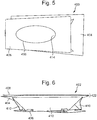
- the carrier 400 is an integral part of a package 402.
- the carrier 400 comprises a top sheet 404 and a bottom sheet 406.
- the package 400 further comprises a cover sheet 408 bonded to the top sheet 404.
- the top sheet 404 comprises a plurality of flaps 410 and tabs 412.
- the flaps 410 are also generally trapezoidal and form sloping side walls of a single pocket 414.
- the bottom sheet 406 rather than being a continuous sheet, has an aperture 416 through which the interior space of the pocket 414 may be viewed.
- the tabs 412 of the top sheet 404 will be bonded to the bottom sheet 406 at locations 418 around the aperture 416.
- the carrier 400 of this embodiment is a part of a container 402 which contains a cover sheet 408 bonded to the top sheet 404.
- glue may be applied around peripheral regions 420 of the top sheet 404 and/or cover sheet 408 to effect the bonding.
- other forms of bonding for example heat sealing may be used.
- the container 402 may, as shown, have a peripheral flange 422 where the top sheet 404 and cover sheet 408 overlap.
- the cover sheet 408 and/or top sheet 404 could be formed with hanger holes or other formations in the flange 422 to facilitate display of the container 402.
- the hanger holes or the like could be provided in a wider section 424 of the flange 422.
- the carrier 400 of this embodiment may be erected in a similar manner to that of the first embodiment, a product then filled into the pocket 414 and the cover sheet 408 then attached to the top sheet 404 to close the container 402.
- This embodiment is a similar to the second embodiment above, but with differently shaped flaps.
- the flaps 410 are generally trapezoidal and substantially close the sides of the tapering pocket 414
- the flaps 410 are generally rectangular and create a pocket 414 which has vertical, rather than sloping walls.
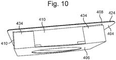
- sizable gaps 430 are formed in the end regions of the longitudinal sides of the pocket 414.
- the bottom sheet 406 is formed with flaps 434 at its ends 436 which in the erected carrier 400 are folded up and attached to the top sheet flaps 410 as shown in Figure 10 to close the gaps 430.
- the carrier 100 of the first embodiment may be provided with a cover sheet as in the second and third embodiment and the bottom sheet 6 of that embodiment may only partially close the base of each pocket such that at least a portion of the base of the pocket 20 remains open.
- the cover sheet may be omitted.
- a filled carrier may be inserted into a container, e.g. a pre-erected carton.
- the carrier may be filled with product and inserted into a container, and/or have a cover sheet bonded thereto.
- the third embodiment may also be adapted to produce tapering pockets 414 as in the second embodiment by suitable sizing of the flaps 410.
Landscapes
- Engineering & Computer Science (AREA)
- Mechanical Engineering (AREA)
- Chemical & Material Sciences (AREA)
- Composite Materials (AREA)
- Cartons (AREA)
- Packages (AREA)
Claims (15)
- Support (2) réalisé en carton, papier cartonné ou autre matériau de feuille pliable de poids léger, comprenant :une feuille supérieure (4) définissant une ou plusieurs poches (20) pour la réception des un ou plusieurs produits ; etune feuille inférieure (6) attachée à la feuille supérieure (4) ;dans lequel la feuille supérieure (4) comprend un ou plusieurs ensembles (30) respectifs de volets (32) pour la formation des poches (20) respectives, chaque volet (32) étant relié par articulation à une extrémité proximale (36) à une surface supérieure (38) de la feuille supérieure (4) autour d'une ligne d'articulation de volet (40) respectif définie autour d'une arête supérieure (42) de la poche (20) respective et pliée autour de la ligne d'articulation de volet (40) respective pour définir une paroi latérale de poche ;la feuille supérieure (4) comprenant en outre des pattes (50) respectives reliées par articulation à des extrémités distales (46) des volets (32) respectifs autour de lignes de pliage de patte (52) respective et pliées autour d'une ligne de pliage de patte (52) respective de sorte à se trouver le long d'une base de la poche (20) ;la feuille inférieure (6) étant collée aux pattes (50) respectives dans un rapport de face-à-face pour fermer au moins une portion de la base de la poche (20) ;dans lequel chaque poche (20) est définie par un ensemble de volets comprenant quatre volets (32, 32a, 32b, 32c, 32d) agencés dans deux paires opposées, dans lequel les pattes (50a, 50b) sur une première paire de volets opposés (32a, 32b) sont alignées l'une sur l'autre le long d'un axe longitudinal (A) de la poche (20) et les pattes (50c, 50d) sur l'autre paire de volets opposés (32c, 32d) sont décalées l'une de l'autre par rapport à un axe transversal (B) de la poche (20) dans une direction le long de l'axe longitudinal (A) de la poche (20).
- Support selon la revendication 1, dans lequel les pattes (50a, 50b, 50c, 50d) sont agencées dans une rangée le long de l'axe longitudinal (A) de la poche (20), avec les pattes alignées (50a, 50b) agencées aux extrémités de la rangée et les pattes décalées (50c, 50d) agencées entre les pattes alignées (50a, 50b).
- Support selon la revendication 1 ou la revendication 2, dans lequel un ou plusieurs volets de chaque ensemble (50) est anglé de sorte à définir une poche effilée.
- Support selon l'une quelconque des revendications précédentes, comprenant en outre une ou plusieurs pattes de positionnement (42) s'étendant vers l'intérieur depuis l'arête supérieure de chaque poche (20).
- Support selon la revendication 4, dans lequel la patte de positionnement (42) est libérée du volet (50) respectif attaché à cette arête.
- Support selon l'une quelconque des revendications précédentes, dans lequel la feuille supérieure (4) et la feuille inférieure (6) sont reliées le long d'arêtes respectives de celles-ci par un panneau latéral (12) relié par articulation aux arêtes latérales respectives.
- Support selon l'une quelconque des revendications précédentes, dans lequel la feuille inférieure (406) comprend en outre un ou plusieurs volets (434) qui sont pliés pour couvrir des ouvertures (430) formées dans les parois latérales des poches (414) entre les volets de feuille supérieure (410), les volets de feuille inférieure (434) recouvrant facultativement les volets de feuille supérieure (410) et étant collés à ceux-ci.
- Support selon l'une quelconque des revendications précédentes, dans lequel la feuille inférieure (406) comprend en outre un ou plusieurs orifices (416) formés dans celle-ci, selon lequel les contenus d'une poche (414) sont accessibles ou peuvent être vus.
- Support selon l'une quelconque des revendications précédentes, comprenant en outre une feuille de couverture (408) attachée sur la feuille supérieure (404) pour fermer les une ou plusieurs poches dans le support (400).
- Contenant comprenant un support selon l'une quelconque des revendications précédentes reçu dans celui-ci.
- Ébauche (100) de carton, papier cartonné ou autre matériau de feuille pliable de poids léger, pour la production d'une feuille supérieure (4) d'un support (2) selon la revendication 1, l'ébauche (100) comprenant :une feuille (4) comprenant un ou plusieurs ensembles (30) de volets (32) définis dedans par des lignes découpées (34), chaque volet (32) d'un ensemble (30) étant relié par articulation à la feuille à une extrémité proximale (36) à environ une ligne d'articulation de volet respectif (40), les lignes d'articulation de volet (40) d'un ensemble (30) de volets (32) étant agencées pour définir une arête d'une poche (20) respective et pliables hors de la feuille pour définir des parois latérales de la poche (20) ;des pattes (50) respectives définies dedans par des lignes découpées (55), chaque patte (50) étant reliée par articulation en option à une extrémité distale (46) d'un volet respectif (32) autour d'une ligne de pliage de patte respective (52) et pliable autour de la ligne de pliage de patte (52) de sorte à se trouver le long d'une portion de base de la poche (20) ;dans laquelle chaque ensemble (30) de volets (32) comprend quatre volets (32a, 32b, 32c, 32d) agencés dans deux paires opposées, dans laquelle les pattes (50a, 50b) sur une paire de volets opposés (32a, 32b) dans chaque ensemble (30) sont alignées l'une sur l'autre, et les pattes (50c, 50d) sur l'autre paire de volets opposés (32c, 32d) sont latéralement décalées l'une de l'autre ;facultativement dans laquelle les pattes (50a, 50b, 50c, 50d) sur les deux paires de volets (32a, 32b, 32c, 32d) sont agencées dans une rangée.
- Procédé de fabrication d'un support selon l'une quelconque des revendications 1 à 9 en utilisant une ébauche selon la revendication 11, comprenant :le pliage des volets (32) des ensembles (30) respectifs de volets (32) autour de leurs lignes d'articulation de volet (34) respectif pour former des parois latérales des poches (20) respectives ;le pliage des pattes (50) autour des lignes d'articulation de patte (52) respective dans une position de collage ; etle collage d'une feuille inférieure (6) aux pattes (50) pour fermer au moins partiellement la base des poches (20) respectives.
- Procédé selon la revendication 12, dans lequel le pliage comprend le pressage d'un outil de formation de poche (200) dans l'ébauche (100) pour plier les volets (32) et les pattes (50).
- Procédé selon la revendication 12 ou 13, dans lequel le collage comprend le passage d'un pistolet à colle ou d'une roue (300) sur les pattes pliées (50), le placement de la feuille inférieure (6) sur les pattes collées (50) et le pressage des pattes (50) et de la feuille inférieure (6) ensemble, ou le collage thermique.
- Procédé selon la revendication 12, 13 ou 14, comprenant en outre le remplissage des une ou plusieurs poches avec le produit et l'attache ensuite d'une feuille de couverture sur les poches remplies.
Applications Claiming Priority (1)
| Application Number | Priority Date | Filing Date | Title |
|---|---|---|---|
| GB1900566.9A GB2580609A (en) | 2019-01-15 | 2019-01-15 | Carrier |
Publications (2)
| Publication Number | Publication Date |
|---|---|
| EP3683158A1 EP3683158A1 (fr) | 2020-07-22 |
| EP3683158B1 true EP3683158B1 (fr) | 2021-11-10 |
Family
ID=65528166
Family Applications (1)
| Application Number | Title | Priority Date | Filing Date |
|---|---|---|---|
| EP20151790.1A Active EP3683158B1 (fr) | 2019-01-15 | 2020-01-14 | Support |
Country Status (3)
| Country | Link |
|---|---|
| US (2) | US11542081B2 (fr) |
| EP (1) | EP3683158B1 (fr) |
| GB (1) | GB2580609A (fr) |
Families Citing this family (4)
| Publication number | Priority date | Publication date | Assignee | Title |
|---|---|---|---|---|
| GB2580609A (en) | 2019-01-15 | 2020-07-29 | Multi Packaging Solutions Uk Ltd | Carrier |
| GB2589146A (en) * | 2019-11-25 | 2021-05-26 | Multi Packaging Solutions Uk Ltd | Tray |
| US20220063889A1 (en) * | 2020-08-25 | 2022-03-03 | Michael Ozzie Bowman | Packing brace |
| DE102022119953A1 (de) * | 2022-08-08 | 2024-02-08 | Van Genechten Packaging N.V. | Verpackung |
Family Cites Families (29)
| Publication number | Priority date | Publication date | Assignee | Title |
|---|---|---|---|---|
| US1356588A (en) * | 1920-01-03 | 1920-10-26 | Bacher David | Display device |
| US1631080A (en) * | 1925-01-22 | 1927-05-31 | Owen Card Publishing Co Inc | Display box |
| US1922571A (en) * | 1931-02-05 | 1933-08-15 | Irving A Deline | Box construction |
| US2258716A (en) * | 1937-10-19 | 1941-10-14 | Ralph Reginald | Confectionery display package |
| FR72561E (fr) | 1957-12-05 | 1960-04-14 | Chevalets pour l'empaquetage des ampoules pharmaceutiques et objets analogues | |
| FR1478568A (fr) | 1966-03-15 | 1967-04-28 | Chevalet porte-ampoules | |
| FR1490713A (fr) | 1966-06-23 | 1967-08-04 | Leguay | Emballages, plus spécialement pour objets de forme allongée tels que des ampoules pharmaceutiques |
| US3489269A (en) * | 1966-10-06 | 1970-01-13 | Burt & Co F N | Display cartons |
| US3595382A (en) * | 1969-06-25 | 1971-07-27 | Swissmart Inc | Display container |
| FR2129295A5 (fr) | 1971-03-16 | 1972-10-27 | Favre Jacques | |
| DE8225471U1 (de) | 1982-09-07 | 1983-06-30 | Europa Carton Ag, 2000 Hamburg | Aus faltbarem Material wie Pappe Wellpappe od dgl bestehender einstueckiger vorgefalzter Zuschnitt |
| US4469271A (en) * | 1982-09-30 | 1984-09-04 | Federal Paper Board Co., Inc. | Multi-pocket tray |
| IT1239850B (it) * | 1990-01-10 | 1993-11-15 | Cartotecnica Chierese S.P.A. | Elemento di cartoncino fustellato per trattenere e presentare prodottidolciari e simili |
| DE9102785U1 (de) | 1991-03-08 | 1991-05-29 | E. Gundlach GmbH & Co KG, 4800 Bielefeld | Halterung zur Aufnahme einer Anzahl von Einzelprodukten in einer Verpackung |
| US5407076A (en) | 1994-06-07 | 1995-04-18 | Milestones Products, Inc. | Combined greeting card and product container, and blank therefor |
| DE29803952U1 (de) | 1998-03-06 | 1999-07-15 | FCP Europa Carton Faltschachtel GmbH, 20095 Hamburg | Träger |
| US6474473B2 (en) * | 1999-12-20 | 2002-11-05 | International Paper Company | Shipping and display container for bottles |
| WO2003042070A1 (fr) | 2001-11-17 | 2003-05-22 | Beone Cnr Co., Ltd. | Boite d'oeufs en carton |
| TW542209U (en) * | 2002-06-28 | 2003-07-11 | Quanta Comp Inc | Stereoscopic inner spacer |
| FR2902410B1 (fr) | 2006-06-16 | 2008-09-12 | Smurfit Kappa France Sas Soc P | Emballage de type plateau ou barquette, en un materiau semi-rigide |
| TWI310357B (en) * | 2006-09-27 | 2009-06-01 | Quanta Comp Inc | Stereoscopic inner spacer |
| JP5473475B2 (ja) | 2009-08-19 | 2014-04-16 | ユーテック株式会社 | 段ボール製のビン収納箱 |
| ITBO20110664A1 (it) | 2011-11-21 | 2013-05-22 | Marchesini Group Spa | Contenitore in cartone per flaconi e fustellato per ottenere tale contenitore |
| ITBO20110767A1 (it) | 2011-12-29 | 2013-06-30 | Marchesini Group Spa | Contenitore in cartone per ricevere flaconi in configurazione orizzontale e fustellato per ottenere tale contenitore |
| ITTO20121146A1 (it) | 2012-12-24 | 2014-06-25 | Soremartec Sa | Dispositivo di posizionamento e ritenzione di prodotti dolciari incartati ed assieme di sbozzati piani per la realizzazione di tale dispositivo |
| US11124345B1 (en) * | 2017-08-02 | 2021-09-21 | Amazon Technologies, Inc. | Electronic device packaging |
| CN207090068U (zh) | 2017-08-02 | 2018-03-13 | 刘军 | 一种蛋托 |
| GB2580608A (en) | 2019-01-15 | 2020-07-29 | Multi Packaging Solutions Uk Ltd | Product support |
| GB2580609A (en) | 2019-01-15 | 2020-07-29 | Multi Packaging Solutions Uk Ltd | Carrier |
-
2019
- 2019-01-15 GB GB1900566.9A patent/GB2580609A/en not_active Withdrawn
-
2020
- 2020-01-14 EP EP20151790.1A patent/EP3683158B1/fr active Active
- 2020-01-14 US US16/742,226 patent/US11542081B2/en active Active
-
2023
- 2023-01-03 US US18/092,625 patent/US12583658B2/en active Active
Also Published As
| Publication number | Publication date |
|---|---|
| US20230219733A1 (en) | 2023-07-13 |
| US11542081B2 (en) | 2023-01-03 |
| US12583658B2 (en) | 2026-03-24 |
| EP3683158A1 (fr) | 2020-07-22 |
| GB201900566D0 (en) | 2019-03-06 |
| GB2580609A (en) | 2020-07-29 |
| US20200223610A1 (en) | 2020-07-16 |
Similar Documents
| Publication | Publication Date | Title |
|---|---|---|
| US12583658B2 (en) | Carrier | |
| US9783334B2 (en) | Shipping and display container | |
| US6948617B2 (en) | Stackable container with support flanges | |
| US4421229A (en) | Double tray case | |
| RU2550482C2 (ru) | Картонная коробка с двумя раздатчиками, подлежащими повторной герметизации | |
| CN106660655B (zh) | 具有支撑柱和孔口的展示托盘 | |
| US20110253587A1 (en) | Carton tray | |
| US5044498A (en) | Packaging device of the tray type for a plurality of articles, more particularly for pots containing fresh milk products such as yoghurts or similar | |
| KR20130136498A (ko) | 용기 패키지 | |
| US7410062B2 (en) | Box | |
| JP2010526730A (ja) | ボトル包装箱及び対応する切り抜き材 | |
| JP2008532875A (ja) | 複数の先細り状の容器を収容するためのカートン | |
| US9597851B2 (en) | Push folding of carton blanks | |
| US5447269A (en) | Multiple unit box and blank therefor | |
| JP2018507143A (ja) | 板紙カートン及びカートンブランク | |
| GB2220406A (en) | Tray | |
| US20040232039A1 (en) | Multi-purpose shipping and display container | |
| CN109923046B (zh) | 包装盒和包装盒坯件 | |
| EP3831733B1 (fr) | Plateau | |
| US4938415A (en) | Container apparatus for friable or granular material | |
| US20060144910A1 (en) | Container and container blank usable with a liquid impermeable bag | |
| CN114728724A (zh) | 物品承载器、坯件和构建物品承载器的方法 | |
| US3334800A (en) | Packaging trays for confections | |
| US5090178A (en) | Method of assembly for simplified container | |
| US3938703A (en) | Dispensing carton for nestable cups |
Legal Events
| Date | Code | Title | Description |
|---|---|---|---|
| PUAI | Public reference made under article 153(3) epc to a published international application that has entered the european phase |
Free format text: ORIGINAL CODE: 0009012 |
|
| STAA | Information on the status of an ep patent application or granted ep patent |
Free format text: STATUS: THE APPLICATION HAS BEEN PUBLISHED |
|
| AK | Designated contracting states |
Kind code of ref document: A1 Designated state(s): AL AT BE BG CH CY CZ DE DK EE ES FI FR GB GR HR HU IE IS IT LI LT LU LV MC MK MT NL NO PL PT RO RS SE SI SK SM TR |
|
| AX | Request for extension of the european patent |
Extension state: BA ME |
|
| STAA | Information on the status of an ep patent application or granted ep patent |
Free format text: STATUS: REQUEST FOR EXAMINATION WAS MADE |
|
| 17P | Request for examination filed |
Effective date: 20210122 |
|
| RBV | Designated contracting states (corrected) |
Designated state(s): AL AT BE BG CH CY CZ DE DK EE ES FI FR GB GR HR HU IE IS IT LI LT LU LV MC MK MT NL NO PL PT RO RS SE SI SK SM TR |
|
| GRAP | Despatch of communication of intention to grant a patent |
Free format text: ORIGINAL CODE: EPIDOSNIGR1 |
|
| STAA | Information on the status of an ep patent application or granted ep patent |
Free format text: STATUS: GRANT OF PATENT IS INTENDED |
|
| INTG | Intention to grant announced |
Effective date: 20210519 |
|
| GRAS | Grant fee paid |
Free format text: ORIGINAL CODE: EPIDOSNIGR3 |
|
| GRAA | (expected) grant |
Free format text: ORIGINAL CODE: 0009210 |
|
| STAA | Information on the status of an ep patent application or granted ep patent |
Free format text: STATUS: THE PATENT HAS BEEN GRANTED |
|
| AK | Designated contracting states |
Kind code of ref document: B1 Designated state(s): AL AT BE BG CH CY CZ DE DK EE ES FI FR GB GR HR HU IE IS IT LI LT LU LV MC MK MT NL NO PL PT RO RS SE SI SK SM TR |
|
| REG | Reference to a national code |
Ref country code: GB Ref legal event code: FG4D |
|
| REG | Reference to a national code |
Ref country code: AT Ref legal event code: REF Ref document number: 1445895 Country of ref document: AT Kind code of ref document: T Effective date: 20211115 Ref country code: CH Ref legal event code: EP |
|
| REG | Reference to a national code |
Ref country code: DE Ref legal event code: R096 Ref document number: 602020000922 Country of ref document: DE |
|
| REG | Reference to a national code |
Ref country code: IE Ref legal event code: FG4D |
|
| REG | Reference to a national code |
Ref country code: NL Ref legal event code: FP |
|
| REG | Reference to a national code |
Ref country code: LT Ref legal event code: MG9D |
|
| REG | Reference to a national code |
Ref country code: AT Ref legal event code: MK05 Ref document number: 1445895 Country of ref document: AT Kind code of ref document: T Effective date: 20211110 |
|
| PG25 | Lapsed in a contracting state [announced via postgrant information from national office to epo] |
Ref country code: RS Free format text: LAPSE BECAUSE OF FAILURE TO SUBMIT A TRANSLATION OF THE DESCRIPTION OR TO PAY THE FEE WITHIN THE PRESCRIBED TIME-LIMIT Effective date: 20211110 Ref country code: LT Free format text: LAPSE BECAUSE OF FAILURE TO SUBMIT A TRANSLATION OF THE DESCRIPTION OR TO PAY THE FEE WITHIN THE PRESCRIBED TIME-LIMIT Effective date: 20211110 Ref country code: FI Free format text: LAPSE BECAUSE OF FAILURE TO SUBMIT A TRANSLATION OF THE DESCRIPTION OR TO PAY THE FEE WITHIN THE PRESCRIBED TIME-LIMIT Effective date: 20211110 Ref country code: BG Free format text: LAPSE BECAUSE OF FAILURE TO SUBMIT A TRANSLATION OF THE DESCRIPTION OR TO PAY THE FEE WITHIN THE PRESCRIBED TIME-LIMIT Effective date: 20220210 Ref country code: AT Free format text: LAPSE BECAUSE OF FAILURE TO SUBMIT A TRANSLATION OF THE DESCRIPTION OR TO PAY THE FEE WITHIN THE PRESCRIBED TIME-LIMIT Effective date: 20211110 |
|
| PG25 | Lapsed in a contracting state [announced via postgrant information from national office to epo] |
Ref country code: IS Free format text: LAPSE BECAUSE OF FAILURE TO SUBMIT A TRANSLATION OF THE DESCRIPTION OR TO PAY THE FEE WITHIN THE PRESCRIBED TIME-LIMIT Effective date: 20220310 Ref country code: SE Free format text: LAPSE BECAUSE OF FAILURE TO SUBMIT A TRANSLATION OF THE DESCRIPTION OR TO PAY THE FEE WITHIN THE PRESCRIBED TIME-LIMIT Effective date: 20211110 Ref country code: PT Free format text: LAPSE BECAUSE OF FAILURE TO SUBMIT A TRANSLATION OF THE DESCRIPTION OR TO PAY THE FEE WITHIN THE PRESCRIBED TIME-LIMIT Effective date: 20220310 Ref country code: PL Free format text: LAPSE BECAUSE OF FAILURE TO SUBMIT A TRANSLATION OF THE DESCRIPTION OR TO PAY THE FEE WITHIN THE PRESCRIBED TIME-LIMIT Effective date: 20211110 Ref country code: NO Free format text: LAPSE BECAUSE OF FAILURE TO SUBMIT A TRANSLATION OF THE DESCRIPTION OR TO PAY THE FEE WITHIN THE PRESCRIBED TIME-LIMIT Effective date: 20220210 Ref country code: LV Free format text: LAPSE BECAUSE OF FAILURE TO SUBMIT A TRANSLATION OF THE DESCRIPTION OR TO PAY THE FEE WITHIN THE PRESCRIBED TIME-LIMIT Effective date: 20211110 Ref country code: HR Free format text: LAPSE BECAUSE OF FAILURE TO SUBMIT A TRANSLATION OF THE DESCRIPTION OR TO PAY THE FEE WITHIN THE PRESCRIBED TIME-LIMIT Effective date: 20211110 Ref country code: GR Free format text: LAPSE BECAUSE OF FAILURE TO SUBMIT A TRANSLATION OF THE DESCRIPTION OR TO PAY THE FEE WITHIN THE PRESCRIBED TIME-LIMIT Effective date: 20220211 Ref country code: ES Free format text: LAPSE BECAUSE OF FAILURE TO SUBMIT A TRANSLATION OF THE DESCRIPTION OR TO PAY THE FEE WITHIN THE PRESCRIBED TIME-LIMIT Effective date: 20211110 |
|
| PG25 | Lapsed in a contracting state [announced via postgrant information from national office to epo] |
Ref country code: SM Free format text: LAPSE BECAUSE OF FAILURE TO SUBMIT A TRANSLATION OF THE DESCRIPTION OR TO PAY THE FEE WITHIN THE PRESCRIBED TIME-LIMIT Effective date: 20211110 Ref country code: SK Free format text: LAPSE BECAUSE OF FAILURE TO SUBMIT A TRANSLATION OF THE DESCRIPTION OR TO PAY THE FEE WITHIN THE PRESCRIBED TIME-LIMIT Effective date: 20211110 Ref country code: RO Free format text: LAPSE BECAUSE OF FAILURE TO SUBMIT A TRANSLATION OF THE DESCRIPTION OR TO PAY THE FEE WITHIN THE PRESCRIBED TIME-LIMIT Effective date: 20211110 Ref country code: EE Free format text: LAPSE BECAUSE OF FAILURE TO SUBMIT A TRANSLATION OF THE DESCRIPTION OR TO PAY THE FEE WITHIN THE PRESCRIBED TIME-LIMIT Effective date: 20211110 Ref country code: DK Free format text: LAPSE BECAUSE OF FAILURE TO SUBMIT A TRANSLATION OF THE DESCRIPTION OR TO PAY THE FEE WITHIN THE PRESCRIBED TIME-LIMIT Effective date: 20211110 Ref country code: CZ Free format text: LAPSE BECAUSE OF FAILURE TO SUBMIT A TRANSLATION OF THE DESCRIPTION OR TO PAY THE FEE WITHIN THE PRESCRIBED TIME-LIMIT Effective date: 20211110 |
|
| REG | Reference to a national code |
Ref country code: DE Ref legal event code: R097 Ref document number: 602020000922 Country of ref document: DE |
|
| PG25 | Lapsed in a contracting state [announced via postgrant information from national office to epo] |
Ref country code: MC Free format text: LAPSE BECAUSE OF FAILURE TO SUBMIT A TRANSLATION OF THE DESCRIPTION OR TO PAY THE FEE WITHIN THE PRESCRIBED TIME-LIMIT Effective date: 20211110 |
|
| PLBE | No opposition filed within time limit |
Free format text: ORIGINAL CODE: 0009261 |
|
| STAA | Information on the status of an ep patent application or granted ep patent |
Free format text: STATUS: NO OPPOSITION FILED WITHIN TIME LIMIT |
|
| REG | Reference to a national code |
Ref country code: BE Ref legal event code: MM Effective date: 20220131 |
|
| 26N | No opposition filed |
Effective date: 20220811 |
|
| PG25 | Lapsed in a contracting state [announced via postgrant information from national office to epo] |
Ref country code: LU Free format text: LAPSE BECAUSE OF NON-PAYMENT OF DUE FEES Effective date: 20220114 Ref country code: AL Free format text: LAPSE BECAUSE OF FAILURE TO SUBMIT A TRANSLATION OF THE DESCRIPTION OR TO PAY THE FEE WITHIN THE PRESCRIBED TIME-LIMIT Effective date: 20211110 |
|
| PG25 | Lapsed in a contracting state [announced via postgrant information from national office to epo] |
Ref country code: SI Free format text: LAPSE BECAUSE OF FAILURE TO SUBMIT A TRANSLATION OF THE DESCRIPTION OR TO PAY THE FEE WITHIN THE PRESCRIBED TIME-LIMIT Effective date: 20211110 Ref country code: BE Free format text: LAPSE BECAUSE OF NON-PAYMENT OF DUE FEES Effective date: 20220131 |
|
| PGFP | Annual fee paid to national office [announced via postgrant information from national office to epo] |
Ref country code: IT Payment date: 20230131 Year of fee payment: 4 |
|
| P01 | Opt-out of the competence of the unified patent court (upc) registered |
Effective date: 20230601 |
|
| REG | Reference to a national code |
Ref country code: CH Ref legal event code: PL |
|
| REG | Reference to a national code |
Ref country code: NL Ref legal event code: MM Effective date: 20230201 |
|
| PG25 | Lapsed in a contracting state [announced via postgrant information from national office to epo] |
Ref country code: NL Free format text: LAPSE BECAUSE OF NON-PAYMENT OF DUE FEES Effective date: 20230201 Ref country code: LI Free format text: LAPSE BECAUSE OF NON-PAYMENT OF DUE FEES Effective date: 20230131 Ref country code: CH Free format text: LAPSE BECAUSE OF NON-PAYMENT OF DUE FEES Effective date: 20230131 |
|
| PG25 | Lapsed in a contracting state [announced via postgrant information from national office to epo] |
Ref country code: MK Free format text: LAPSE BECAUSE OF FAILURE TO SUBMIT A TRANSLATION OF THE DESCRIPTION OR TO PAY THE FEE WITHIN THE PRESCRIBED TIME-LIMIT Effective date: 20211110 Ref country code: CY Free format text: LAPSE BECAUSE OF FAILURE TO SUBMIT A TRANSLATION OF THE DESCRIPTION OR TO PAY THE FEE WITHIN THE PRESCRIBED TIME-LIMIT Effective date: 20211110 |
|
| PG25 | Lapsed in a contracting state [announced via postgrant information from national office to epo] |
Ref country code: HU Free format text: LAPSE BECAUSE OF FAILURE TO SUBMIT A TRANSLATION OF THE DESCRIPTION OR TO PAY THE FEE WITHIN THE PRESCRIBED TIME-LIMIT; INVALID AB INITIO Effective date: 20200114 |
|
| PG25 | Lapsed in a contracting state [announced via postgrant information from national office to epo] |
Ref country code: TR Free format text: LAPSE BECAUSE OF FAILURE TO SUBMIT A TRANSLATION OF THE DESCRIPTION OR TO PAY THE FEE WITHIN THE PRESCRIBED TIME-LIMIT Effective date: 20211110 |
|
| PG25 | Lapsed in a contracting state [announced via postgrant information from national office to epo] |
Ref country code: MT Free format text: LAPSE BECAUSE OF FAILURE TO SUBMIT A TRANSLATION OF THE DESCRIPTION OR TO PAY THE FEE WITHIN THE PRESCRIBED TIME-LIMIT Effective date: 20211110 |
|
| PG25 | Lapsed in a contracting state [announced via postgrant information from national office to epo] |
Ref country code: IT Free format text: LAPSE BECAUSE OF NON-PAYMENT OF DUE FEES Effective date: 20240114 |
|
| PGFP | Annual fee paid to national office [announced via postgrant information from national office to epo] |
Ref country code: GB Payment date: 20260127 Year of fee payment: 7 |
|
| PGFP | Annual fee paid to national office [announced via postgrant information from national office to epo] |
Ref country code: DE Payment date: 20260128 Year of fee payment: 7 Ref country code: IE Payment date: 20260127 Year of fee payment: 7 |
|
| PGFP | Annual fee paid to national office [announced via postgrant information from national office to epo] |
Ref country code: FR Payment date: 20260126 Year of fee payment: 7 |