EP3684154B1 - Élément d'insert thermoconducteur pour unité électronique - Google Patents
Élément d'insert thermoconducteur pour unité électronique Download PDFInfo
- Publication number
- EP3684154B1 EP3684154B1 EP19152913.0A EP19152913A EP3684154B1 EP 3684154 B1 EP3684154 B1 EP 3684154B1 EP 19152913 A EP19152913 A EP 19152913A EP 3684154 B1 EP3684154 B1 EP 3684154B1
- Authority
- EP
- European Patent Office
- Prior art keywords
- thermally conductive
- conductive insert
- insert element
- top cover
- electronic unit
- Prior art date
- Legal status (The legal status is an assumption and is not a legal conclusion. Google has not performed a legal analysis and makes no representation as to the accuracy of the status listed.)
- Active
Links
Images



Classifications
-
- H—ELECTRICITY
- H05—ELECTRIC TECHNIQUES NOT OTHERWISE PROVIDED FOR
- H05K—PRINTED CIRCUITS; CASINGS OR CONSTRUCTIONAL DETAILS OF ELECTRIC APPARATUS; MANUFACTURE OF ASSEMBLAGES OF ELECTRICAL COMPONENTS
- H05K7/00—Constructional details common to different types of electric apparatus
- H05K7/20—Modifications to facilitate cooling, ventilating, or heating
- H05K7/2039—Modifications to facilitate cooling, ventilating, or heating characterised by the heat transfer by conduction from the heat generating element to a dissipating body
- H05K7/20409—Outer radiating structures on heat dissipating housings, e.g. fins integrated with the housing
- H05K7/20418—Outer radiating structures on heat dissipating housings, e.g. fins integrated with the housing the radiating structures being additional and fastened onto the housing
-
- H—ELECTRICITY
- H05—ELECTRIC TECHNIQUES NOT OTHERWISE PROVIDED FOR
- H05K—PRINTED CIRCUITS; CASINGS OR CONSTRUCTIONAL DETAILS OF ELECTRIC APPARATUS; MANUFACTURE OF ASSEMBLAGES OF ELECTRICAL COMPONENTS
- H05K7/00—Constructional details common to different types of electric apparatus
- H05K7/20—Modifications to facilitate cooling, ventilating, or heating
- H05K7/20845—Modifications to facilitate cooling, ventilating, or heating for automotive electronic casings
- H05K7/20854—Heat transfer by conduction from internal heat source to heat radiating structure
-
- H—ELECTRICITY
- H05—ELECTRIC TECHNIQUES NOT OTHERWISE PROVIDED FOR
- H05K—PRINTED CIRCUITS; CASINGS OR CONSTRUCTIONAL DETAILS OF ELECTRIC APPARATUS; MANUFACTURE OF ASSEMBLAGES OF ELECTRICAL COMPONENTS
- H05K5/00—Casings, cabinets or drawers for electric apparatus
- H05K5/06—Hermetically-sealed casings
- H05K5/069—Other details of the casing, e.g. wall structure, passage for a connector, a cable, a shaft
-
- H—ELECTRICITY
- H05—ELECTRIC TECHNIQUES NOT OTHERWISE PROVIDED FOR
- H05K—PRINTED CIRCUITS; CASINGS OR CONSTRUCTIONAL DETAILS OF ELECTRIC APPARATUS; MANUFACTURE OF ASSEMBLAGES OF ELECTRICAL COMPONENTS
- H05K7/00—Constructional details common to different types of electric apparatus
- H05K7/20—Modifications to facilitate cooling, ventilating, or heating
- H05K7/20218—Modifications to facilitate cooling, ventilating, or heating using a liquid coolant without phase change in electronic enclosures
- H05K7/20254—Cold plates transferring heat from heat source to coolant
-
- H—ELECTRICITY
- H05—ELECTRIC TECHNIQUES NOT OTHERWISE PROVIDED FOR
- H05K—PRINTED CIRCUITS; CASINGS OR CONSTRUCTIONAL DETAILS OF ELECTRIC APPARATUS; MANUFACTURE OF ASSEMBLAGES OF ELECTRICAL COMPONENTS
- H05K7/00—Constructional details common to different types of electric apparatus
- H05K7/20—Modifications to facilitate cooling, ventilating, or heating
- H05K7/2039—Modifications to facilitate cooling, ventilating, or heating characterised by the heat transfer by conduction from the heat generating element to a dissipating body
- H05K7/20436—Inner thermal coupling elements in heat dissipating housings, e.g. protrusions or depressions integrally formed in the housing
- H05K7/20445—Inner thermal coupling elements in heat dissipating housings, e.g. protrusions or depressions integrally formed in the housing the coupling element being an additional piece, e.g. thermal standoff
-
- H—ELECTRICITY
- H10—SEMICONDUCTOR DEVICES; ELECTRIC SOLID-STATE DEVICES NOT OTHERWISE PROVIDED FOR
- H10W—GENERIC PACKAGES, INTERCONNECTIONS, CONNECTORS OR OTHER CONSTRUCTIONAL DETAILS OF DEVICES COVERED BY CLASS H10
- H10W40/00—Arrangements for thermal protection or thermal control
- H10W40/20—Arrangements for cooling
- H10W40/22—Arrangements for cooling characterised by their shape, e.g. having conical or cylindrical projections
-
- H—ELECTRICITY
- H10—SEMICONDUCTOR DEVICES; ELECTRIC SOLID-STATE DEVICES NOT OTHERWISE PROVIDED FOR
- H10W—GENERIC PACKAGES, INTERCONNECTIONS, CONNECTORS OR OTHER CONSTRUCTIONAL DETAILS OF DEVICES COVERED BY CLASS H10
- H10W40/00—Arrangements for thermal protection or thermal control
- H10W40/40—Arrangements for thermal protection or thermal control involving heat exchange by flowing fluids
- H10W40/47—Arrangements for thermal protection or thermal control involving heat exchange by flowing fluids by flowing liquids, e.g. forced water cooling
-
- H—ELECTRICITY
- H10—SEMICONDUCTOR DEVICES; ELECTRIC SOLID-STATE DEVICES NOT OTHERWISE PROVIDED FOR
- H10W—GENERIC PACKAGES, INTERCONNECTIONS, CONNECTORS OR OTHER CONSTRUCTIONAL DETAILS OF DEVICES COVERED BY CLASS H10
- H10W40/00—Arrangements for thermal protection or thermal control
- H10W40/70—Fillings or auxiliary members in containers or in encapsulations for thermal protection or control
- H10W40/77—Auxiliary members characterised by their shape
Definitions
- the invention relates to an electronic unit in accordance with the preamble of claim 1 (see EP 2 916 636 A1 ) arranged with a thermally conductive insert element for optimized heat dissipation from a printed circuit board of the electronic unit.
- Typical enclosure for automotive electronics unit is designed for protecting fragile devices from unwanted mechanical loads, dust and humidity.
- housing is also used to enable heat removal allowing the devices to operate within safe temperature limits.
- heat dissipation is frequently obtained through conduction via the so-called pedestals, which are housing geometrical features allowing for establishing thermal joints between heat sources and housing walls.
- pedestals which are housing geometrical features allowing for establishing thermal joints between heat sources and housing walls.
- complex structures such has water cooling systems, are implemented in addition with the heat conduction obtained with the die casted housing.
- US 2013/0329367 A1 discloses an electronic device with a printed circuit board and an electronic component in a housing, a heat-dissipating element and a thermal conductive element.
- a bottom extremity of the heat-dissipating element is not in direct thermal contact with the electronic component, but the thermal conductive element is arranged between the electronic component and a top extremity of the heat-dissipating element.
- an electronic unit is provided according to claim 1.
- the first thermal conductive insert element may comprise a blind cavity extending from its opened top extremity entirely fixed around the first opening, to its bottom wall extremity in thermal contact with the first heating source element.
- the first thermally conductive insert element may have a thermal conductivity greater than the top cover.
- the fixing means may be watertight fixing means around the first opening.
- the top extremity of the first thermally conductive insert element comprises a flange arranged around the top extremity and fixed with the top cover around the first opening.
- the top cover comprises a thickness reduction area all around the first opening corresponding to the thickness of the flange, the flange being arranged onto the reduced thickness area such that the surface area of the top cover comprising the flange is a flat surface.
- the thickness reduction may also be greater than the thickness of the flange such that the flange does not protrude on the top cover.
- the top cover may be made of a liquid coolant cold plate, the top cover comprising a coolant liquid inlet, a coolant liquid outlet, and liquid coolant wall guides configured to convey the coolant liquid from the coolant liquid inlet to the first thermally conductive insert element and from the first thermally conductive insert element to the coolant liquid outlet.
- the housing may comprise a top wall having at least one another opening; the top cover being arranged onto the top wall; the first thermally conductive insert element being arranged through the another opening.
- the top wall may be made of plastic material.
- the first thermally conductive insert element and the top cover may be made of metallic material, preferably, the first thermally conductive insert element may be made of cooper alloy material and the top cover may be made of an aluminum alloy material.
- the fixing means may comprise a brazed joint or the fixing means may comprise an adhesive paste joint especially when the housing is not made of metallic material.
- the printed circuit board may comprise a second heating source element on the top layer of the printed circuit board; the top cover may comprise a second opening such that the electronic unit may comprise a second thermally conductive insert element distinct from the housing and extending from its top extremity arranged around the second opening, to its bottom extremity in thermal contact with the second heating source element such that heating dissipation of the second heating source element is allowed.
- the second thermally conductive insert element may comprise a thermal conductivity different to the first thermally conductive insert element.
- the second thermally conductive insert element may be made of silver material.
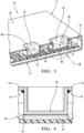
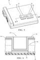
- the electronic unit 10 may be an electronic control unit for car or any kind of electronic unit 10, said electronic unit 10 comprises a housing 12.
- the housing 12 comprises a bottom wall 14 on which a printed circuit board 16 is arranged and a top wall or a top cover 18 that comprises a first opening 20 and a second opening 22 or a first cut-out and a second cut-out.
- the first opening 20 and the second opening 22 are opened square shape and are respectively arranged above a first heating source element 24 and a second heating source element 26, both heating source elements 24, 26 being arranged on the top layer of the printed circuit board 16.
- An heating source element 24, 26 in the sense of the present disclosure relates to an electronic component that may generate heat during operation, or to any conductive layout pattern as copper track pattern, that also may generate heat when a current is flowing through said pattern.
- the electronic unit 10 comprises a first thermally conductive insert element 28, or thermally conductive pedestal, and a second thermally conductive insert element 30, both thermally conductive insert element being distinct from the housing 12.
- the first thermally conductive insert element 28 and the second thermally conductive element 30 cooperate mechanically respectively with the first opening 20 and the second opening 22 of the top cover 18, and respectively with the first heating source element 24 and the second heating source element 26 such that heating dissipation of the first heating source element 24 and the heating dissipation of the second heating source element 26 are allowed.
- each thermally conductive insert element 28, 30 are distinct from the housing 12, they may have thermal conductivity different than the housing 12.
- the present description provides the advantage of using standard housing 12 material such as plastic or aluminum while the thermally conductive insert elements 28, 30 comprise greater thermal conductivity than the housing 12.
- Both thermally conductive insert elements 28, 30 may have the same thermal conductivity or different thermal conductivity.
- both thermally conductive insert elements 28, 30 may be made of copper alloy, or if one of the two heating source element 24, 26 needs better heat dissipation, the thermally conductive insert element 28 relative to said heating source element 24 may be made of silver.
- each thermally conductive insert element 28, 30 comprises a blind cavity 32, 34 or a blind hole extending from its opened top extremity entirely fixed around its associated opening 20, 22, to its bottom wall extremity 36, 38 in thermal contact with the its associated heating source element 24, 26.
- FIG 4 one embodiment of the arrangement of the second thermally conductive insert element 30 is shown. Arrangement of the first thermally conductive insert element 28 may be similar.
- the top layer of the printed circuit board 16 comprises one electronic component as the second heating source element 26.
- Said electronic component may be as a non-limiting examples, a microcontroller or a solid state power switch.
- the bottom wall extremity 38 of the second thermally conductive insert element 30 is in thermal contact with the second heating source element 26. More particularly, the second heating source element 26 is in thermal contact with the second thermally conductive insert element 30 by means of a thermal interface material 40 as thermal paste arranged on the top surface of the second heating source element 26. Alternatively, the bottom wall extremity 38 of the second thermally conductive insert element 30 may be in direct thermal contact with the top surface of the second heating source element 26, i.e. without thermal interface material such that heat transfer is less optimized.
- the opened top extremity of the second thermally conductive insert element 30 is arranged inside the second opening 22 and comprises fixing means 42 cooperating with the around inside of the second opening 22 of the top cover 18 such that watertight is guaranteed between the second thermally conductive insert element 30 and the top cover 18.
- the fixing means 42 are configured to entirely fix the top extremity of a thermally conductive insert element 28, 30 with the top cover 18 around an opening 20, 22 of the top cover 18.
- the fixing means 42 comprise an adhesive paste joint that suits with most of the housing 12 materials that have to be fixed with the thermally conductive insert element 28, 30.
- first thermally conductive insert element 28 and the second thermally conductive insert element 30 are also made of metallic material
- said first and second thermally conductive insert elements 28, 30 may be respectively brazed with the around inside of the first opening 20 and the second opening 22 of the top cover 18 such that a brazed join is formed between each thermally conductive insert element 28, 30 and the top cover 18 providing watertight effect.
- the opened top extremity of the thermally conductive insert may be brazed with the around of the opening on top of the top cover 18 or on the bottom side of the top cover 18.
- the top cover 18 of the electronic unit 10 comprises a variant of the first thermally conductive insert element 28 and the second thermally conductive insert element 30.
- the top cover 18 is equipped with a third thermally conductive insert element 44 and a fourth thermally conductive insert element 46 that differ from the first thermally conductive insert element 28 and the second thermally conductive insert element 30 by comprising a flange 48, 50 around their top extremity.
- the flange 48, 50 of each thermally conductive insert element 44, 46 improves the fixing strength of the third thermally conductive insert element 44 and of the fourth thermally conductive insert element 46 with the top cover 18.
- said flanges 48, 50 improve respectively the heating transfer from the third thermally conductive insert element 44 and from the fourth thermally conductive insert element 46 to the metallic top cover 18.
- the flange 50 is fixed around the second opening 22 of the top cover 18, on the top surface, or external surface, of the top cover 18.
- the flange 50 may be fixed on the bottom surface, or internal surface, of the top cover 18.
- the flange 50 may be glued to the top cover 18 by the usage of adhesive paste joint.
- the flange 50 may be brazed with the top cover 18 such that a brazed joint is formed between the flange 50 and the top cover 18.
- the top cover 18 is arranged with the fourth thermally conductive insert element 46.
- the flange 50 is mounted around the second opening 22, on the top surface of the top cover 18. More particularly, the top cover 18 comprises a thickness reduction area 52 all around to first opening 20.
- the thickness reduction is equal or greater than the thickness of the flange 50 such that the flange 50 does not protrude on the top surface of the top cover 18. While the thickness reduction is equal to the corresponding thickness of the flange 50, the surface area of the top cover 18 comprising the flange 50 is a flat surface.
- the embodiment shown in figure 7 differs from the embodiment of figure 5 and figure 6 such that the top surface of the top cover 18 wherein the flange 50 is mounted, i.e. the thickness reduction area 52 of the top cover 18 comprising the flange 50, is a flat surface. In that case, the flange 50 of the fourth thermally conductive insert element 46 does not affect the top surface plan of the top cover 18.
- the electronic unit 10 comprises a cold plate 54.
- the cold plate 54 is arranged on the top surface of the housing 12.
- the mechanical cooperation between the cold plate 54 and the thermally conductive insert elements 44, 46 is similar than the mechanical cooperation between the top cover 18 and the third thermally conductive insert element 44 and the fourth the thermally conductive insert element 46 shown at figure 5, figure 6 and figure 7 .
- the cold plate 54 comprises two other openings 56, 58 such that the thermally conductive insert elements 44, 46 are fixed in a similar manner than described by the figures 5, 6 and 7 .
- thermally conductive insert elements arranged with the cold plate 54 may be similar that the first thermally conductive insert element 28 and the second thermally conductive insert element 30 as shown at figure 2 , figure 3 and figure 4 .
- each thermally conductive insert element 44, 46 fixed with the cold plate 54 is arranged through an opening 20, 22 of the top wall of the housing 12 of the electronic unit 10, i.e. an opening 20, 22 of the top cover 18 as defined at figure 1 .
- the thermally conductive insert elements 44, 46 are not any more primarily fixed with the housing 12, but they are primarily fixed with the cold plate 54.
- adhesive paste joint may be added between the cold plate 54 and the top wall of the housing 12.
- the cold plate 54 is more particularly a liquid coolant cold plate 54 comprising a coolant liquid inlet 60 and a coolant liquid outlet 62.
- the cold plate 54 comprises liquid coolant wall guides 64, 66, 68, as liquid coolant deflector, configured to convey the liquid coolant from the coolant liquid inlet 60 to each thermally conductive insert element 44, 46, and to convey the liquid coolant from each thermally conductive insert element 44, 46 to the coolant liquid outlet 62.
- each thermally conductive insert element 44, 46 may be attached at their top extremity to a single cold plate to increase their thermal conductivity.
- the invention is not limited to the shape of the openings 20, 22 of the top wall and of the top cover and of the thermally conductive insert elements 28, 30, 44, 46 shown at the figure 7 .
- Other shape may be also suitable for the invention.
- other thermal conductive material than the ones cited in that present description may also be suitable for the thermally conductive insert elements 28, 30, 44, 46.
- the number of thermally conductive insert elements 28, 30, 44, 46 and their corresponding heating source element 24, 26 may be greater than two.
Landscapes
- Engineering & Computer Science (AREA)
- Microelectronics & Electronic Packaging (AREA)
- Physics & Mathematics (AREA)
- Thermal Sciences (AREA)
- Cooling Or The Like Of Electrical Apparatus (AREA)
- Cooling Or The Like Of Semiconductors Or Solid State Devices (AREA)
Claims (13)
- Unité électronique (10) comprenant :un boîtier (12) comprenant au moins une première ouverture (20) et un couvercle supérieur (18) ;une carte de circuit imprimé (16) montée à l'intérieur du boîtier (12) et comprenant au moins un premier élément source de chaleur (24) sur la couche supérieure de la carte de circuit imprimé (16) ;au moins un premier élément insert thermiquement conducteur (28) distinct du boîtier (12) ;le couvercle supérieur (18) comprend la première ouverture (20) ;le premier élément insert thermiquement conducteur (28) s'étend de son extrémité supérieure disposée autour de la première ouverture (20) à son extrémité inférieure en contact thermique avec le premier élément source de chaleur (24), de sorte à permettre une dissipation de chaleur du premier élément source de chaleur (24) ;des moyens de fixation (42) sont configurés pour fixer entièrement l'extrémité supérieure du premier élément insert thermiquement conducteur (28) avec le couvercle supérieur (18) autour de la première ouverture (20) ; etcaractérisée en ce quel'extrémité supérieure du premier élément insert thermiquement conducteur (28) comprend une bride (50) disposée autour de l'extrémité supérieure et fixée avec le couvercle supérieur (18) autour de la première ouverture (20), le couvercle supérieur (18) comprenant une zone de réduction d'épaisseur (52) tout autour de la première ouverture (20), ladite réduction d'épaisseur étant égale ou supérieure à l'épaisseur de la bride (50), de sorte que la bride (50) ne dépasse pas de la surface supérieure du couvercle supérieur (18).
- Unité électronique (10) selon la revendication précédente, caractérisée en ce que le premier élément insert thermiquement conducteur (28) comprend une cavité aveugle (32) s'étendant de son extrémité supérieure ouverte entièrement fixée autour de la première ouverture (20) à son extrémité de paroi inférieure (36) en contact thermique avec le premier élément source de chaleur (24).
- Unité électronique (10) selon l'une quelconque des revendications précédentes, caractérisée en ce que le premier élément insert thermiquement conducteur (28) a une conductivité thermique supérieure à celle du couvercle supérieur (18).
- Unité électronique (10) selon l'une quelconque des revendications précédentes, caractérisée en ce que les moyens de fixation (42) sont des moyens de fixation étanches (42) autour de la première ouverture (20).
- Unité électronique (10) selon l'une quelconque des revendications précédentes, dans laquelle le couvercle supérieur (18) est constitué d'une plaque froide à réfrigérant liquide (54), le couvercle supérieur (18) comprenant une entrée de liquide réfrigérant (60), une sortie de liquide réfrigérant (62) et des guides verticaux de réfrigérant liquide (64, 66, 68) configurés pour acheminer le réfrigérant liquide de l'entrée de liquide réfrigérant (60) au premier élément insert thermiquement conducteur (28) et du premier élément insert thermiquement conducteur (28) à la sortie de liquide réfrigérant (62).
- Unité électronique (10) selon l'une quelconque des revendications précédentes, caractérisée en ce que le boîtier (12) comprend une paroi supérieure ayant au moins une autre ouverture, le couvercle supérieur (18) étant disposé sur la paroi supérieure, le premier élément insert thermiquement conducteur (28) étant disposé à travers l'autre ouverture.
- Unité électronique (10) selon la revendication 6, caractérisée en ce que la paroi supérieure est en matière plastique.
- Unité électronique (10) selon l'une quelconque des revendications précédentes, caractérisée en ce que le premier élément insert thermiquement conducteur (28) et le couvercle supérieur (18) sont en matériau métallique.
- Unité électronique (10) selon la revendication 8, caractérisée en ce que le premier élément insert thermiquement conducteur (28) est en alliage de cuivre et que le couvercle supérieur (18) est en alliage d'aluminium.
- Unité électronique (10) selon l'une quelconque des revendications précédentes, caractérisée en ce que les moyens de fixation (42) comprennent un joint en pâte adhésive.
- Unité électronique (10) selon l'une quelconque des revendications 8 et 9, caractérisée en ce que les moyens de fixation (42) comprennent un joint brasé.
- Unité électronique (10) selon l'une quelconque des revendications précédentes, caractérisée en ce quela carte de circuit imprimé (16) comprend un second élément source de chaleur (26) sur la couche supérieure de la carte de circuit imprimé (16) ;le couvercle supérieur (18) comprend une seconde ouverture (22) ;l'unité électronique (10) comprend un second élément insert thermiquement conducteur (30) distinct du boîtier (12) et s'étendant de son extrémité supérieure disposée autour de la seconde ouverture (22) à son extrémité inférieure (38) en contact thermique avec le second élément source de chaleur (26), de sorte à permettre une dissipation de chaleur du second élément source de chaleur (26) ; ledit second élément insert thermiquement conducteur (30) présentant une conductivité thermique différente de celle du premier élément insert thermiquement conducteur (28).
- Unité électronique (10) selon la revendication 12, caractérisée en ce que le second élément insert thermiquement conducteur (30) est en matériau argenté.
Priority Applications (3)
| Application Number | Priority Date | Filing Date | Title |
|---|---|---|---|
| EP19152913.0A EP3684154B1 (fr) | 2019-01-21 | 2019-01-21 | Élément d'insert thermoconducteur pour unité électronique |
| US16/747,097 US11076503B2 (en) | 2019-01-21 | 2020-01-20 | Thermally conductive insert element for electronic unit |
| CN202010069014.4A CN111465258B (zh) | 2019-01-21 | 2020-01-21 | 用于电子单元的导热插入元件 |
Applications Claiming Priority (1)
| Application Number | Priority Date | Filing Date | Title |
|---|---|---|---|
| EP19152913.0A EP3684154B1 (fr) | 2019-01-21 | 2019-01-21 | Élément d'insert thermoconducteur pour unité électronique |
Publications (2)
| Publication Number | Publication Date |
|---|---|
| EP3684154A1 EP3684154A1 (fr) | 2020-07-22 |
| EP3684154B1 true EP3684154B1 (fr) | 2024-03-06 |
Family
ID=65138943
Family Applications (1)
| Application Number | Title | Priority Date | Filing Date |
|---|---|---|---|
| EP19152913.0A Active EP3684154B1 (fr) | 2019-01-21 | 2019-01-21 | Élément d'insert thermoconducteur pour unité électronique |
Country Status (3)
| Country | Link |
|---|---|
| US (1) | US11076503B2 (fr) |
| EP (1) | EP3684154B1 (fr) |
| CN (1) | CN111465258B (fr) |
Families Citing this family (6)
| Publication number | Priority date | Publication date | Assignee | Title |
|---|---|---|---|---|
| EP3923689B1 (fr) * | 2020-06-12 | 2024-04-24 | Aptiv Technologies AG | Dispositif de refroidissement et son procédé de fabrication |
| GB2611028A (en) | 2021-09-17 | 2023-03-29 | Aptiv Tech Ltd | A method of fitting a cooling device to a circuit board and a circuit board cooling device |
| US12543298B1 (en) * | 2023-01-31 | 2026-02-03 | Zoox, Inc. | Composite power electronics cover |
| CN120530723A (zh) * | 2023-03-14 | 2025-08-22 | 株式会社爱信 | 电源模块 |
| WO2026018294A1 (fr) * | 2024-07-16 | 2026-01-22 | Astemo株式会社 | Dispositif de commande électronique |
| DE102024209383A1 (de) * | 2024-09-27 | 2026-04-02 | Robert Bosch Gesellschaft mit beschränkter Haftung | Kühlvorrichtung zur Kühlung eines mit Wärme erzeugenden elektrischen Bauelementen bestückten elektronischen Schaltungsteils und Thermomanagementmodul mit einer solchen Kühlvorrichtung |
Citations (1)
| Publication number | Priority date | Publication date | Assignee | Title |
|---|---|---|---|---|
| US20130329367A1 (en) * | 2012-06-07 | 2013-12-12 | Askey Computer Corp. | Electronic device having heat-dissipating structure |
Family Cites Families (21)
| Publication number | Priority date | Publication date | Assignee | Title |
|---|---|---|---|---|
| US2780757A (en) * | 1955-08-02 | 1957-02-05 | Texas Instruments Inc | Rectifier structure |
| US4138692A (en) * | 1977-09-12 | 1979-02-06 | International Business Machines Corporation | Gas encapsulated cooling module |
| JP3877098B2 (ja) * | 1997-11-25 | 2007-02-07 | 株式会社デンソー | 液冷回路装置 |
| JP2002046482A (ja) * | 2000-07-31 | 2002-02-12 | Honda Motor Co Ltd | ヒートシンク式冷却装置 |
| US6881077B2 (en) * | 2002-07-22 | 2005-04-19 | Siemens Vdo Automotive Corporation | Automotive control module housing |
| TW556475B (en) * | 2003-02-19 | 2003-10-01 | Accton Technology Corp | A cover apparatus for dissipating heat and shielding electromagnetic interference |
| US7180745B2 (en) * | 2003-10-10 | 2007-02-20 | Delphi Technologies, Inc. | Flip chip heat sink package and method |
| JP2006190707A (ja) * | 2004-12-28 | 2006-07-20 | Toshiba Corp | 電子機器とこの電子機器が適用されるテレビジョン受像装置 |
| JP4819071B2 (ja) * | 2008-02-06 | 2011-11-16 | 本田技研工業株式会社 | 電気車両及び車両用dc/dcコンバータの冷却方法 |
| JP4785878B2 (ja) * | 2008-02-06 | 2011-10-05 | 本田技研工業株式会社 | 冷却装置及び該冷却装置を備える電気車両 |
| JP5402200B2 (ja) * | 2009-04-20 | 2014-01-29 | 株式会社リコー | 熱移動機構及び情報機器 |
| KR101289313B1 (ko) * | 2009-05-22 | 2013-07-24 | 엘에스산전 주식회사 | 수냉식 쿨러 및 이를 구비한 인버터 |
| JP2011054640A (ja) * | 2009-08-31 | 2011-03-17 | Funai Electric Co Ltd | シールドパッケージ基板 |
| KR20130029044A (ko) * | 2010-02-25 | 2013-03-21 | 톰슨 라이센싱 | 퀵 릴리스 스냅들이 은닉된 소형 다층 방사성 냉각 케이스 |
| CN103858067A (zh) * | 2011-03-09 | 2014-06-11 | 汤姆逊许可公司 | 具有卡扣式热沉和智能卡读取器的机顶盒或服务器 |
| WO2013009982A1 (fr) * | 2011-07-14 | 2013-01-17 | Thomson Licensing | Boîtier à poser avec dissipateur thermique encliquetable et lecteur de cartes à puce avec fixation de retenue du dissipateur thermique |
| KR101608182B1 (ko) * | 2012-08-02 | 2016-03-31 | 미쓰비시덴키 가부시키가이샤 | 방열판 |
| JP2014093414A (ja) * | 2012-11-02 | 2014-05-19 | Hitachi Automotive Systems Ltd | 電子制御装置 |
| US20170038154A1 (en) * | 2015-08-06 | 2017-02-09 | Chaun-Choung Technology Corp. | Vapor chamber structure having stretchable heated part |
| JP6540496B2 (ja) * | 2015-12-17 | 2019-07-10 | 株式会社デンソー | 電力変換装置 |
| DE102016106180A1 (de) * | 2016-04-05 | 2017-10-05 | Dr. Ing. H.C. F. Porsche Aktiengesellschaft | Kühlvorrichtung für die Kühlung wenigstens einer elektrischen Komponente eines Fahrzeugs |
-
2019
- 2019-01-21 EP EP19152913.0A patent/EP3684154B1/fr active Active
-
2020
- 2020-01-20 US US16/747,097 patent/US11076503B2/en active Active
- 2020-01-21 CN CN202010069014.4A patent/CN111465258B/zh active Active
Patent Citations (1)
| Publication number | Priority date | Publication date | Assignee | Title |
|---|---|---|---|---|
| US20130329367A1 (en) * | 2012-06-07 | 2013-12-12 | Askey Computer Corp. | Electronic device having heat-dissipating structure |
Also Published As
| Publication number | Publication date |
|---|---|
| CN111465258A (zh) | 2020-07-28 |
| US11076503B2 (en) | 2021-07-27 |
| EP3684154A1 (fr) | 2020-07-22 |
| US20200236811A1 (en) | 2020-07-23 |
| CN111465258B (zh) | 2022-10-14 |
Similar Documents
| Publication | Publication Date | Title |
|---|---|---|
| EP3684154B1 (fr) | Élément d'insert thermoconducteur pour unité électronique | |
| US6661664B2 (en) | Electronic module with high cooling power | |
| US7742307B2 (en) | High performance power device | |
| JP4404726B2 (ja) | 車載用電力変換装置 | |
| US6408934B1 (en) | Cooling module | |
| JP4859823B2 (ja) | 冷却装置およびそれを用いた電子機器 | |
| EP2738803A2 (fr) | Dissipateur de chaleur à changement de phase pour la gestion thermique transitoire | |
| JP5783212B2 (ja) | 電源装置 | |
| JPWO2017154696A1 (ja) | 回路構成体 | |
| WO2005028259A1 (fr) | Structure d'assemblage d'une carte d'equipement de circuit de vehicule et carte associee | |
| JP6918225B2 (ja) | 電力変換装置 | |
| WO2019130442A1 (fr) | Dispositif d'entraînement de moteur | |
| US20070217148A1 (en) | Power supply cooling | |
| WO2016147345A1 (fr) | Module d'alimentation électrique et unité extérieure de climatiseur l'utilisant | |
| CN207219146U (zh) | 用于电路板散热的散热装置 | |
| JP2006271063A (ja) | バスバーの冷却構造 | |
| KR101360730B1 (ko) | 방열 장치 및 이를 포함하는 전기 장치 | |
| JPS5893264A (ja) | デバイスの冷却装置 | |
| JP6098705B1 (ja) | インバータ | |
| EP2816591B1 (fr) | Dispositif de refroidissement de composant électrique et équipement de source de chaleur pour un appareil à cycle de réfrigération équipé de ce dispositif | |
| CN211210276U (zh) | 一种散热结构 | |
| JP6794757B2 (ja) | 電子回路装置 | |
| US11937407B2 (en) | Photo-etched chassis cooling walls | |
| JP2006173243A (ja) | プリント配線板、及びプリント回路板の放熱構造 | |
| CN219576843U (zh) | 电源功率装置 |
Legal Events
| Date | Code | Title | Description |
|---|---|---|---|
| PUAI | Public reference made under article 153(3) epc to a published international application that has entered the european phase |
Free format text: ORIGINAL CODE: 0009012 |
|
| STAA | Information on the status of an ep patent application or granted ep patent |
Free format text: STATUS: THE APPLICATION HAS BEEN PUBLISHED |
|
| AK | Designated contracting states |
Kind code of ref document: A1 Designated state(s): AL AT BE BG CH CY CZ DE DK EE ES FI FR GB GR HR HU IE IS IT LI LT LU LV MC MK MT NL NO PL PT RO RS SE SI SK SM TR |
|
| AX | Request for extension of the european patent |
Extension state: BA ME |
|
| STAA | Information on the status of an ep patent application or granted ep patent |
Free format text: STATUS: REQUEST FOR EXAMINATION WAS MADE |
|
| 17P | Request for examination filed |
Effective date: 20210114 |
|
| RBV | Designated contracting states (corrected) |
Designated state(s): AL AT BE BG CH CY CZ DE DK EE ES FI FR GB GR HR HU IE IS IT LI LT LU LV MC MK MT NL NO PL PT RO RS SE SI SK SM TR |
|
| STAA | Information on the status of an ep patent application or granted ep patent |
Free format text: STATUS: EXAMINATION IS IN PROGRESS |
|
| 17Q | First examination report despatched |
Effective date: 20220401 |
|
| RAP3 | Party data changed (applicant data changed or rights of an application transferred) |
Owner name: APTIV TECHNOLOGIES LIMITED |
|
| GRAP | Despatch of communication of intention to grant a patent |
Free format text: ORIGINAL CODE: EPIDOSNIGR1 |
|
| STAA | Information on the status of an ep patent application or granted ep patent |
Free format text: STATUS: GRANT OF PATENT IS INTENDED |
|
| INTG | Intention to grant announced |
Effective date: 20231108 |
|
| GRAS | Grant fee paid |
Free format text: ORIGINAL CODE: EPIDOSNIGR3 |
|
| P01 | Opt-out of the competence of the unified patent court (upc) registered |
Effective date: 20231110 |
|
| GRAA | (expected) grant |
Free format text: ORIGINAL CODE: 0009210 |
|
| STAA | Information on the status of an ep patent application or granted ep patent |
Free format text: STATUS: THE PATENT HAS BEEN GRANTED |
|
| AK | Designated contracting states |
Kind code of ref document: B1 Designated state(s): AL AT BE BG CH CY CZ DE DK EE ES FI FR GB GR HR HU IE IS IT LI LT LU LV MC MK MT NL NO PL PT RO RS SE SI SK SM TR |
|
| REG | Reference to a national code |
Ref country code: GB Ref legal event code: FG4D |
|
| REG | Reference to a national code |
Ref country code: CH Ref legal event code: EP |
|
| REG | Reference to a national code |
Ref country code: IE Ref legal event code: FG4D |
|
| REG | Reference to a national code |
Ref country code: DE Ref legal event code: R096 Ref document number: 602019047611 Country of ref document: DE |
|
| REG | Reference to a national code |
Ref country code: LT Ref legal event code: MG9D |
|
| PG25 | Lapsed in a contracting state [announced via postgrant information from national office to epo] |
Ref country code: LT Free format text: LAPSE BECAUSE OF FAILURE TO SUBMIT A TRANSLATION OF THE DESCRIPTION OR TO PAY THE FEE WITHIN THE PRESCRIBED TIME-LIMIT Effective date: 20240306 |
|
| REG | Reference to a national code |
Ref country code: NL Ref legal event code: MP Effective date: 20240306 |
|
| PG25 | Lapsed in a contracting state [announced via postgrant information from national office to epo] |
Ref country code: GR Free format text: LAPSE BECAUSE OF FAILURE TO SUBMIT A TRANSLATION OF THE DESCRIPTION OR TO PAY THE FEE WITHIN THE PRESCRIBED TIME-LIMIT Effective date: 20240607 |
|
| PG25 | Lapsed in a contracting state [announced via postgrant information from national office to epo] |
Ref country code: RS Free format text: LAPSE BECAUSE OF FAILURE TO SUBMIT A TRANSLATION OF THE DESCRIPTION OR TO PAY THE FEE WITHIN THE PRESCRIBED TIME-LIMIT Effective date: 20240606 Ref country code: HR Free format text: LAPSE BECAUSE OF FAILURE TO SUBMIT A TRANSLATION OF THE DESCRIPTION OR TO PAY THE FEE WITHIN THE PRESCRIBED TIME-LIMIT Effective date: 20240306 |
|
| PG25 | Lapsed in a contracting state [announced via postgrant information from national office to epo] |
Ref country code: ES Free format text: LAPSE BECAUSE OF FAILURE TO SUBMIT A TRANSLATION OF THE DESCRIPTION OR TO PAY THE FEE WITHIN THE PRESCRIBED TIME-LIMIT Effective date: 20240306 |
|
| PG25 | Lapsed in a contracting state [announced via postgrant information from national office to epo] |
Ref country code: RS Free format text: LAPSE BECAUSE OF FAILURE TO SUBMIT A TRANSLATION OF THE DESCRIPTION OR TO PAY THE FEE WITHIN THE PRESCRIBED TIME-LIMIT Effective date: 20240606 Ref country code: NO Free format text: LAPSE BECAUSE OF FAILURE TO SUBMIT A TRANSLATION OF THE DESCRIPTION OR TO PAY THE FEE WITHIN THE PRESCRIBED TIME-LIMIT Effective date: 20240606 Ref country code: LT Free format text: LAPSE BECAUSE OF FAILURE TO SUBMIT A TRANSLATION OF THE DESCRIPTION OR TO PAY THE FEE WITHIN THE PRESCRIBED TIME-LIMIT Effective date: 20240306 Ref country code: HR Free format text: LAPSE BECAUSE OF FAILURE TO SUBMIT A TRANSLATION OF THE DESCRIPTION OR TO PAY THE FEE WITHIN THE PRESCRIBED TIME-LIMIT Effective date: 20240306 Ref country code: GR Free format text: LAPSE BECAUSE OF FAILURE TO SUBMIT A TRANSLATION OF THE DESCRIPTION OR TO PAY THE FEE WITHIN THE PRESCRIBED TIME-LIMIT Effective date: 20240607 Ref country code: FI Free format text: LAPSE BECAUSE OF FAILURE TO SUBMIT A TRANSLATION OF THE DESCRIPTION OR TO PAY THE FEE WITHIN THE PRESCRIBED TIME-LIMIT Effective date: 20240306 Ref country code: ES Free format text: LAPSE BECAUSE OF FAILURE TO SUBMIT A TRANSLATION OF THE DESCRIPTION OR TO PAY THE FEE WITHIN THE PRESCRIBED TIME-LIMIT Effective date: 20240306 Ref country code: BG Free format text: LAPSE BECAUSE OF FAILURE TO SUBMIT A TRANSLATION OF THE DESCRIPTION OR TO PAY THE FEE WITHIN THE PRESCRIBED TIME-LIMIT Effective date: 20240306 |
|
| REG | Reference to a national code |
Ref country code: AT Ref legal event code: MK05 Ref document number: 1664800 Country of ref document: AT Kind code of ref document: T Effective date: 20240306 |
|
| PG25 | Lapsed in a contracting state [announced via postgrant information from national office to epo] |
Ref country code: SE Free format text: LAPSE BECAUSE OF FAILURE TO SUBMIT A TRANSLATION OF THE DESCRIPTION OR TO PAY THE FEE WITHIN THE PRESCRIBED TIME-LIMIT Effective date: 20240306 Ref country code: LV Free format text: LAPSE BECAUSE OF FAILURE TO SUBMIT A TRANSLATION OF THE DESCRIPTION OR TO PAY THE FEE WITHIN THE PRESCRIBED TIME-LIMIT Effective date: 20240306 |
|
| PG25 | Lapsed in a contracting state [announced via postgrant information from national office to epo] |
Ref country code: NL Free format text: LAPSE BECAUSE OF FAILURE TO SUBMIT A TRANSLATION OF THE DESCRIPTION OR TO PAY THE FEE WITHIN THE PRESCRIBED TIME-LIMIT Effective date: 20240306 |
|
| PG25 | Lapsed in a contracting state [announced via postgrant information from national office to epo] |
Ref country code: NL Free format text: LAPSE BECAUSE OF FAILURE TO SUBMIT A TRANSLATION OF THE DESCRIPTION OR TO PAY THE FEE WITHIN THE PRESCRIBED TIME-LIMIT Effective date: 20240306 |
|
| PG25 | Lapsed in a contracting state [announced via postgrant information from national office to epo] |
Ref country code: IS Free format text: LAPSE BECAUSE OF FAILURE TO SUBMIT A TRANSLATION OF THE DESCRIPTION OR TO PAY THE FEE WITHIN THE PRESCRIBED TIME-LIMIT Effective date: 20240706 |
|
| PG25 | Lapsed in a contracting state [announced via postgrant information from national office to epo] |
Ref country code: PT Free format text: LAPSE BECAUSE OF FAILURE TO SUBMIT A TRANSLATION OF THE DESCRIPTION OR TO PAY THE FEE WITHIN THE PRESCRIBED TIME-LIMIT Effective date: 20240708 Ref country code: SM Free format text: LAPSE BECAUSE OF FAILURE TO SUBMIT A TRANSLATION OF THE DESCRIPTION OR TO PAY THE FEE WITHIN THE PRESCRIBED TIME-LIMIT Effective date: 20240306 |
|
| PG25 | Lapsed in a contracting state [announced via postgrant information from national office to epo] |
Ref country code: EE Free format text: LAPSE BECAUSE OF FAILURE TO SUBMIT A TRANSLATION OF THE DESCRIPTION OR TO PAY THE FEE WITHIN THE PRESCRIBED TIME-LIMIT Effective date: 20240306 Ref country code: CZ Free format text: LAPSE BECAUSE OF FAILURE TO SUBMIT A TRANSLATION OF THE DESCRIPTION OR TO PAY THE FEE WITHIN THE PRESCRIBED TIME-LIMIT Effective date: 20240306 |
|
| PG25 | Lapsed in a contracting state [announced via postgrant information from national office to epo] |
Ref country code: AT Free format text: LAPSE BECAUSE OF FAILURE TO SUBMIT A TRANSLATION OF THE DESCRIPTION OR TO PAY THE FEE WITHIN THE PRESCRIBED TIME-LIMIT Effective date: 20240306 |
|
| PG25 | Lapsed in a contracting state [announced via postgrant information from national office to epo] |
Ref country code: PL Free format text: LAPSE BECAUSE OF FAILURE TO SUBMIT A TRANSLATION OF THE DESCRIPTION OR TO PAY THE FEE WITHIN THE PRESCRIBED TIME-LIMIT Effective date: 20240306 |
|
| PG25 | Lapsed in a contracting state [announced via postgrant information from national office to epo] |
Ref country code: SK Free format text: LAPSE BECAUSE OF FAILURE TO SUBMIT A TRANSLATION OF THE DESCRIPTION OR TO PAY THE FEE WITHIN THE PRESCRIBED TIME-LIMIT Effective date: 20240306 |
|
| PG25 | Lapsed in a contracting state [announced via postgrant information from national office to epo] |
Ref country code: SM Free format text: LAPSE BECAUSE OF FAILURE TO SUBMIT A TRANSLATION OF THE DESCRIPTION OR TO PAY THE FEE WITHIN THE PRESCRIBED TIME-LIMIT Effective date: 20240306 Ref country code: SK Free format text: LAPSE BECAUSE OF FAILURE TO SUBMIT A TRANSLATION OF THE DESCRIPTION OR TO PAY THE FEE WITHIN THE PRESCRIBED TIME-LIMIT Effective date: 20240306 Ref country code: RO Free format text: LAPSE BECAUSE OF FAILURE TO SUBMIT A TRANSLATION OF THE DESCRIPTION OR TO PAY THE FEE WITHIN THE PRESCRIBED TIME-LIMIT Effective date: 20240306 Ref country code: PT Free format text: LAPSE BECAUSE OF FAILURE TO SUBMIT A TRANSLATION OF THE DESCRIPTION OR TO PAY THE FEE WITHIN THE PRESCRIBED TIME-LIMIT Effective date: 20240708 Ref country code: PL Free format text: LAPSE BECAUSE OF FAILURE TO SUBMIT A TRANSLATION OF THE DESCRIPTION OR TO PAY THE FEE WITHIN THE PRESCRIBED TIME-LIMIT Effective date: 20240306 Ref country code: IS Free format text: LAPSE BECAUSE OF FAILURE TO SUBMIT A TRANSLATION OF THE DESCRIPTION OR TO PAY THE FEE WITHIN THE PRESCRIBED TIME-LIMIT Effective date: 20240706 Ref country code: EE Free format text: LAPSE BECAUSE OF FAILURE TO SUBMIT A TRANSLATION OF THE DESCRIPTION OR TO PAY THE FEE WITHIN THE PRESCRIBED TIME-LIMIT Effective date: 20240306 Ref country code: CZ Free format text: LAPSE BECAUSE OF FAILURE TO SUBMIT A TRANSLATION OF THE DESCRIPTION OR TO PAY THE FEE WITHIN THE PRESCRIBED TIME-LIMIT Effective date: 20240306 Ref country code: AT Free format text: LAPSE BECAUSE OF FAILURE TO SUBMIT A TRANSLATION OF THE DESCRIPTION OR TO PAY THE FEE WITHIN THE PRESCRIBED TIME-LIMIT Effective date: 20240306 |
|
| PG25 | Lapsed in a contracting state [announced via postgrant information from national office to epo] |
Ref country code: IT Free format text: LAPSE BECAUSE OF FAILURE TO SUBMIT A TRANSLATION OF THE DESCRIPTION OR TO PAY THE FEE WITHIN THE PRESCRIBED TIME-LIMIT Effective date: 20240306 |
|
| REG | Reference to a national code |
Ref country code: DE Ref legal event code: R097 Ref document number: 602019047611 Country of ref document: DE |
|
| PG25 | Lapsed in a contracting state [announced via postgrant information from national office to epo] |
Ref country code: IT Free format text: LAPSE BECAUSE OF FAILURE TO SUBMIT A TRANSLATION OF THE DESCRIPTION OR TO PAY THE FEE WITHIN THE PRESCRIBED TIME-LIMIT Effective date: 20240306 |
|
| PLBE | No opposition filed within time limit |
Free format text: ORIGINAL CODE: 0009261 |
|
| STAA | Information on the status of an ep patent application or granted ep patent |
Free format text: STATUS: NO OPPOSITION FILED WITHIN TIME LIMIT |
|
| PG25 | Lapsed in a contracting state [announced via postgrant information from national office to epo] |
Ref country code: DK Free format text: LAPSE BECAUSE OF FAILURE TO SUBMIT A TRANSLATION OF THE DESCRIPTION OR TO PAY THE FEE WITHIN THE PRESCRIBED TIME-LIMIT Effective date: 20240306 |
|
| PG25 | Lapsed in a contracting state [announced via postgrant information from national office to epo] |
Ref country code: DK Free format text: LAPSE BECAUSE OF FAILURE TO SUBMIT A TRANSLATION OF THE DESCRIPTION OR TO PAY THE FEE WITHIN THE PRESCRIBED TIME-LIMIT Effective date: 20240306 |
|
| 26N | No opposition filed |
Effective date: 20241209 |
|
| PG25 | Lapsed in a contracting state [announced via postgrant information from national office to epo] |
Ref country code: SI Free format text: LAPSE BECAUSE OF FAILURE TO SUBMIT A TRANSLATION OF THE DESCRIPTION OR TO PAY THE FEE WITHIN THE PRESCRIBED TIME-LIMIT Effective date: 20240306 |
|
| REG | Reference to a national code |
Ref country code: DE Ref legal event code: R081 Ref document number: 602019047611 Country of ref document: DE Owner name: APTIV TECHNOLOGIES AG, CH Free format text: FORMER OWNER: APTIV TECHNOLOGIES LIMITED, ST. MICHAEL, BB |
|
| REG | Reference to a national code |
Ref country code: CH Ref legal event code: PL |
|
| PG25 | Lapsed in a contracting state [announced via postgrant information from national office to epo] |
Ref country code: LU Free format text: LAPSE BECAUSE OF NON-PAYMENT OF DUE FEES Effective date: 20250121 Ref country code: MC Free format text: LAPSE BECAUSE OF FAILURE TO SUBMIT A TRANSLATION OF THE DESCRIPTION OR TO PAY THE FEE WITHIN THE PRESCRIBED TIME-LIMIT Effective date: 20240306 |
|
| PG25 | Lapsed in a contracting state [announced via postgrant information from national office to epo] |
Ref country code: BE Free format text: LAPSE BECAUSE OF NON-PAYMENT OF DUE FEES Effective date: 20250131 |
|
| PG25 | Lapsed in a contracting state [announced via postgrant information from national office to epo] |
Ref country code: CH Free format text: LAPSE BECAUSE OF NON-PAYMENT OF DUE FEES Effective date: 20250131 |
|
| REG | Reference to a national code |
Ref country code: BE Ref legal event code: MM Effective date: 20250131 |
|
| PG25 | Lapsed in a contracting state [announced via postgrant information from national office to epo] |
Ref country code: IE Free format text: LAPSE BECAUSE OF NON-PAYMENT OF DUE FEES Effective date: 20250121 |
|
| PGFP | Annual fee paid to national office [announced via postgrant information from national office to epo] |
Ref country code: GB Payment date: 20260112 Year of fee payment: 8 |
|
| PGFP | Annual fee paid to national office [announced via postgrant information from national office to epo] |
Ref country code: DE Payment date: 20251217 Year of fee payment: 8 |
|
| PGFP | Annual fee paid to national office [announced via postgrant information from national office to epo] |
Ref country code: FR Payment date: 20260108 Year of fee payment: 8 |