EP3684536B1 - Maschine für fräsen der oberfläche und verfahren - Google Patents
Maschine für fräsen der oberfläche und verfahren Download PDFInfo
- Publication number
- EP3684536B1 EP3684536B1 EP18796705.4A EP18796705A EP3684536B1 EP 3684536 B1 EP3684536 B1 EP 3684536B1 EP 18796705 A EP18796705 A EP 18796705A EP 3684536 B1 EP3684536 B1 EP 3684536B1
- Authority
- EP
- European Patent Office
- Prior art keywords
- milling
- grinding
- rule
- press
- translation
- Prior art date
- Legal status (The legal status is an assumption and is not a legal conclusion. Google has not performed a legal analysis and makes no representation as to the accuracy of the status listed.)
- Active
Links
Images

Classifications
-
- B—PERFORMING OPERATIONS; TRANSPORTING
- B23—MACHINE TOOLS; METAL-WORKING NOT OTHERWISE PROVIDED FOR
- B23C—MILLING
- B23C3/00—Milling particular work; Special milling operations; Machines therefor
- B23C3/13—Surface milling of plates, sheets or strips
-
- B—PERFORMING OPERATIONS; TRANSPORTING
- B23—MACHINE TOOLS; METAL-WORKING NOT OTHERWISE PROVIDED FOR
- B23C—MILLING
- B23C3/00—Milling particular work; Special milling operations; Machines therefor
Definitions
- the present invention relates to a rectification device and a rectification method according to the preambles of claims 1 and 8.
- Such devices and methods are known from the document FR2834665 A1 .
- the grinding proposed here is a plane grinding and the grinding plane can be vertical.
- the milling ruler (50) is also mounted to move in translation along a direction of translation passing through the point of rotation (52) of the frame (70), parallel to the direction of elongation of the said milling ruler (50) and parallel to the grinding plane.
- the device is configured so that the combined movements of translation of the milling cutter (51) along the milling rule (50) and rotation of the milling rule (50), allow the milling cutter (51) to traverse a multi-shaped two-dimensional grindable surface (80).
- the rotational movement of the milling rule (50) is implemented by means of a belt or a rack and pinion in the form of a worm screw.
- the frame (70) comprises a first face and a second face, opposite the first, and in which means for fixing the frame (70) are disposed on the first face of the frame, and the cutter ( 51) is arranged on the second side.
- the surface to be ground is that of a press platen of an injection molding machine, a die-cutting press or a stamping press.
- the press comprises a set of columns (21-24) parallel to each other, and the grinding device is removably mounted on said set of columns (21-24).
- the present invention allows particularly rapid on-site machining.
- the present invention is advantageously implemented in the field of injection molding 10 which, for brevity, will be the only example illustrated here. This example is non-limiting and those skilled in the art will apply the present invention to other fields presenting the same problem of grinding a flat surface.
- the “injection molding machine” will be referred to as the “press” below.
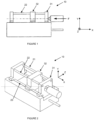
- a press In the field of press molding, a press comprises two press plates 31, 32, see for example the figure 1 . Each press plate supports a respective half-mold (not shown), secured thereto, and removably mounted thereon.
- the two press plates 31, 32 are mounted to move in translation relative to each other, between an open position ( figure 1, figure 2 ) where the two half-molds are spaced from each other, and a closed position (not shown) where the two half-molds are in contact with one another.
- Each press plate 31, 32 has a flat surface which supports a respective half-mold.
- the two flat surfaces of the two plates are parallel to each other, in this case according to the ZoY plane of an orthonormal reference XYZ ( figure 1, figure 2 And Figures 5A, 5B, 5C ).
- the relative translational movement of one press plate with respect to the other is ensured for example by a set of at least one piston (not shown), in particular hydraulic, integral with at least one press plate, according to a direction perpendicular to the plane of the press plates 31, 32, in this case along the direction OX, the other press plate being generally fixed.
- an injection molding machine also comprises a first set of at least one rectilinear guide, in this case in the direction perpendicular to the press plates.
- the first set of at least one rectilinear guide comprises at least two guide columns, "columns" hereinafter briefly, parallel to each other, along which at least one of the two press plates 31, 32 slides , which also makes it possible to maintain the squareness between the two press plates 31, 32.
- the first set of at least one rectilinear guide comprises four columns 21, 22, 23, 24, each column being positioned in a respective corner of the press plate which has a flat rectangular shape. At least one of the columns of said assembly can be secured to a press plate.
- the material to be injected into a half-mold is introduced via a pipe, in the direction illustrated by the arrow F on the figure 1 .
- each half-mold exerts a pressure force on its respective support plate.
- the pressure force can damage said press plate so that it can actually present a depression 40 (depression) compared to the initial flatness of its surface. , which then poses problems for the mould.
- FIG. 4 illustrates in cross section along the plane XoZ a depression 40 of a press plate 31 before grinding.
- a milling rule 50 that is to say a grinding device comprising a milling cutter 51 movable in translation along a rectilinear rule which has a direction of elongation.
- the cutter 51 can move freely between two extreme positions: one illustrated in solid line, the other in dotted lines, the race between these two positions being called L1 according to a milling strip.
- the operation of such a device is cyclical by milling bands.
- the milling rule 50 is clamped to a press plate in a predetermined position.
- the milling cutter 51 then traverses all or part of the milling rule 50 to mill said press plate along this direction.
- the milling rule 50 is manually unclamped from said press plate.
- Another milling cycle can then take place: the milling rule 50 is clamped again to the press plate in another predetermined position and the milling is again implemented along the milling rule 50 for a new strip of milling, etc.
- the present invention makes it possible to overcome these drawbacks and to obtain a rectified surface which is flat.
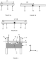
- a grinding device which comprises a frame 70 and a milling ruler 50 secured to the frame 70.
- the frame 70 has a median plane P.
- the milling rule 50 comprises a milling cutter 51 mounted movable in translation, in a milling direction, along said milling rule 50.
- the translational movement of the milling cutter 51 defines a milling strip, according to a stroke of length L1, rectilinear and included in a milling plane, in this case parallel to the median plane P and to the press plates.
- the milling ruler 50 is arranged so that the milling plane is parallel to the plane that the press plate must present once the latter has been rectified.
- the milling rule 50 is mounted integral with the frame 70, for example by a set of screws.
- the milling ruler 50 is mounted so as to be able to move in translation with respect to a point of translation 52 of the frame 70, in a direction of translation parallel to the milling strip, i.e. to say the direction of translation of the cutter 51, and in this case coincides with the latter, according to a rectilinear course of length L2.
- the translation of the milling ruler 50 in no way limits the translation of the cutter 51 along it.
- the milling cutter 51 is mounted on a movable carriage in translation along the milling rule 50.
- the milling rule 50 can move between two extreme positions, one illustrated in a solid line, the other in dotted lines, the stroke between these two positions being called L2.
- the translation movement of the milling cutter 51 can be combined with the translation movement of the milling rule 50.
- the milling cutter 51 always remains in the milling plane, whether the milling cutter 51 only is in translation, the milling ruler 50 only is in translation, or the milling cutter 51 and the milling ruler 50 are simultaneously in translation.
- the total translation distance of the cutter 51 in the milling plane is equal to the stroke L1 of the cutter 51 added to the travel L2 of the milling rule 50, as shown in the Fig. 3C .
- the total translation distance of the milling cutter 51 in the milling plane is twice the stroke of the milling cutter 51 in the milling rule 50.
- the same grinding device can be used to two different press plates 31, 32 to be ground, one of whose dimensions can range from single to double.
- the rectification device according to the invention is less bulky than the solution of the prior art.
- the point of rotation 52 is arranged along the direction of translation of the milling cutter 51, that is to say along a direction merging with the milling strip.
- the rotational movement of the milling ruler 50 is implemented by means of a belt or a rack and pinion in the form of a worm, similarly to the turrets of armored vehicles.
- the milling rule 50 is configured so that the rotational movement of the milling rule 50 keeps the milling cutter 51 in the milling plane.
- the milling cutter 51 is movable in a plane of rotation advantageously parallel with the milling plane, and in this case coinciding with the latter.
- the milling cutter 51 can then traverse a rectifiable surface 80 two-dimensional multiform any, other than the band of prior art milling.
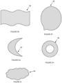
- rectifiable surface 80 in the form of a disk, represented by the hatched area on the figure 5B , or cross-shaped ( Fig. 5C ), which the solutions of the prior art cited above do not allow. It is also possible to machine a rectifiable surface 80 in the shape of an ellipse (not shown) or any other solid surface whose shape results from the combination of rotational and translational movements of the milling rule.
- the rectifiable surface 80 shown hatched on the Fig. 5C presents right angles around the columns 61, 62, 63, 64.
- the rectifiable surface 80 matches the contour of each column and therefore has, locally, a shape curve ( figure 5D ).
- rectifiable surface 80 is illustrated without limitation, for example a shape of a flag ( figure 5E ), bubble ( figure 5F ), crescent ( figure 5G ), ring ( figure 5H ), cloud ( Figure 5I ).
- the same device can be used in a versatile way, to rectify rectifiable surfaces of various shapes; it is therefore adaptable to steric constraints of the rectification environment.
- the total surface of the rectifiable surface 80 can also be, for the same milling cutter 51, greater than that of a milling strip (single movement of translation of the milling cutter along the milling ruler) for said milling cutter.
- the point of rotation 52 of the frame 70 coincides with the point of translation 52, hence the same reference numeral in the present description.
- the rectification device has several advantages.
- the same grinding device therefore the same milling ruler 50, can be used for two plates of different dimensions.
- the rectification device is therefore versatile.
- the frame 70 is integral with the latter, according to any one of the embodiments below.
- the advantage is that the grinding device is not clamped directly to the press plate.
- the disadvantage lies essentially in that the squaring must be carried out twice, once per press plate.
- the rectification device for squaring, provision is made for the rectification device to further comprise a second set of at least one rectilinear guide, each individual rectilinear guide in this case being in the form of a column 61, 62, 63, 64 all of the same length.
- the second set of at least one rectilinear guide comprises as many columns as the first set of at least one rectilinear guide comprises columns and of length less than or equal to the length thereof.
- the direction of the second set of at least one rectilinear guide is substantially parallel to the direction of the first set of at least one rectilinear guide.
- each column 61, 62, 63, 64 is then mounted adjacent to a respective column (see for example Figures 5A, 5B, 5C ).
- each column is mounted close to a respective column.
- Near is meant in contact or at a distance less than a predetermined threshold value.
- the small columns are arranged in a concentric circle with a radius greater than R.
- center O coincides with the point of rotation/translation 52 of the milling ruler 50.
- each end of a column is in contact with a respective plate. Since the balusters are the same length and the contact point between the balusters and the press plates has a flat surface, squaring is achieved quickly and efficiently.
- the adjustment of the squareness can also be achieved by means of a set of feelers which make it possible to position the set of columns 61, 62, 63, 64 so as to optimize the angle between the milling plane and the plane of the surface to be ground.
- the frame 70 can be dismantled from said columns, turned over then reassembled on said columns in order to be able to machine the other press plate, in a similar manner.
- the axis of elongation of the columns is perpendicular to the chassis 70, and the axis of elongation of the columns is perpendicular to the median plane P of the chassis, it it is not necessary to do another squaring operation for the other press plate.
- the parallelism is preserved even by turning over the frame 70.
- Another advantage of the columns resides in that the same frame 70 can be used for several presses having different respective column diameters.
- the present invention allows on-site machining, the rectification device being grafted onto the mechanical part to be machined.
- the cutter 51 can be arranged on the side opposite the fixing means, which allows it to have a greater stroke.
- the grinding of a complete plate can be carried out without the need to disassemble the grinding device, unlike the strip solution of the prior art, thanks to the movements combinations of rotation of the milling rule 50 and translation of the milling cutter 51, possibly supplemented by the translational movement of the milling rule 50 itself.
- the rectifiable surface 80 is generally cross-shaped.
- the entire rectifiable surface 80 can therefore be rectified without dismantling/unclamping the rectification device.
- cutter 51 also means a solid wheel, a cup wheel or a segmented wheel.
Landscapes
- Engineering & Computer Science (AREA)
- Mechanical Engineering (AREA)
- Finish Polishing, Edge Sharpening, And Grinding By Specific Grinding Devices (AREA)
- Milling Processes (AREA)
Claims (10)
- Schleifvorrichtung zum Schleifen einer zu schleifenden Oberfläche, die mindestens eine Vertiefung (40) gemäß einer Schleifebene aufweist, wobei die Vorrichtung Folgendes beinhaltet:- ein Fräslineal (50), das eine gerade und ebene Erstreckungsrichtung aufweist und eine Fräse (51) beinhaltet, die entlang der Erstreckungsrichtung verschiebbar beweglich ist,- wobei die Vorrichtung ferner ein Gestell (70) beinhaltet, an dem das Fräslineal (50) montiert ist,- wobei das Fräslineal (50) mit Bezug auf einen Drehpunkt (52) des Gestells (70) in einer Drehebene drehbar beweglich montiert ist, sodass die Drehebene zu der Schleifebene parallel ist,- wobei die Erstreckungsrichtung in der Drehebene enthalten ist.Dadurch gekennzeichnet, dass:
das Fräslineal (50) ferner gemäß einer Verschieberichtung, die durch den Drehpunkt (52) des Gestells (70) verläuft, parallel zu der Erstreckungsrichtung des Fräslineals (50) und parallel zu der Schleifebene verschiebbar beweglich montiert ist. - Schleifvorrichtung nach Anspruch 1, die so konfiguriert ist, dass die Kombination aus der Verschiebebewegung der Fräse (51) entlang des Fräslineals (50) und der Drehbewegung des Fräslineals (50) der Fräse (51) gestattet, eine vielgestaltige zweidimensionale schleifbare Oberfläche (80) zu durchlaufen.
- Schleifvorrichtung nach einem beliebigen der vorhergehenden Ansprüche, die ferner eine Fernbedienung beinhaltet, die dazu konfiguriert ist, mindestens eine der folgenden Bewegungen anzusteuern:- die Verschiebebewegung der Fräse (51) entlang des Fräslineals (50),- die Verschiebebewegung des Fräslineals (50) und- die Drehbewegung des Fräslineals (50).
- Schleifvorrichtung nach einem beliebigen der vorhergehenden Ansprüche, wobei die Drehbewegung des Fräslineals (50) mit Hilfe eines Riemens oder eines Ritzel-Zahnstangen-Triebs in Form einer Schnecke umgesetzt wird.
- Schleifvorrichtung nach einem beliebigen der vorhergehenden Ansprüche, wobei das Gestell (70) eine erste Seite und eine zweite Seite, die zu der ersten entgegengesetzt ist, beinhaltet und wobei Mittel zur Befestigung des Gestells (70) auf der ersten Seite des Gestells angeordnet sind und die Fräse (51) auf der zweiten Seite angeordnet ist.
- Schleifvorrichtung nach einem beliebigen der vorhergehenden Ansprüche für eine Spritzgusspresse, eine Stanzpresse oder eine Gesenkschmiedepresse, die eine Pressplatte beinhalten, wobei die zu schleifende Oberfläche diejenige der Pressplatte ist.
- Anordnung, die die Schleifvorrichtung nach Anspruch 6 beinhaltet und die Spritzgusspresse, die Stanzpresse oder die Gesenkschmiedepresse beinhaltet, wobei die Presse eine Anordnung von Säulen (21-24) beinhaltet, die untereinander parallel sind, und wobei die Schleifvorrichtung entfernbar an der Anordnung von Säulen (21-24) montiert ist.
- Verfahren zum Schleifen einer zu schleifenden Oberfläche, die mindestens eine Vertiefung (40) aufweist, wobei das Verfahren Schritte beinhaltet, die aus Folgendem bestehen:- Anbringen einer Schleifvorrichtung nach einem beliebigen der vorhergehenden Ansprüche, die ein Fräslineal (50) beinhaltet, das mit Bezug auf einen Drehpunkt (52) und die zu schleifende Oberfläche drehbar beweglich montiert ist, und- Ansteuern, gemäß einer Schleifebene, mindestens einer der folgenden Bewegungen:∘ einer Verschiebebewegung der Fräse (51) entlang einer Erstreckungsrichtung des Fräslineals (50), die in der Schleifebene enthalten ist, dadurch gekennzeichnet, dass sie ferner Folgendes beinhaltet:∘ eine Verschiebebewegung des Fräslineals (50) in einer Verschieberichtung, die zu der Erstreckungsrichtung des Fräslineals (50) parallel ist und zu der Schleifebene parallel ist; und∘ eine Drehbewegung des Fräslineals (50) in einer Drehebene, die mit der Schleifebene zusammenfällt,o wobei das Fräslineal (50) gemäß einer Verschieberichtung, die durch den Drehpunkt (52) des Gestells (70) verläuft, parallel zu der Erstreckungsrichtung des Fräslineals (50) und parallel zu der Schleifebene verschiebbar beweglich montiert ist.
- Schleifverfahren nach Anspruch 8 zum Schleifen von zwei Pressplatten (31, 32) einer Spritzgusspresse (10), wobei die Presse eine Anordnung von Säulen (21, 22, 23, 24) beinhaltet und die Säulchen (61, 62, 63, 64) eine gleiche Länge aufweisen, wobei das Verfahren vor dem Schleifen Schritte zum Herstellen der Rechtwinkligkeit beinhaltet, die aus Folgendem bestehen:- Öffnen der zwei Pressplatten (31, 32),- Montieren jedes Säulchens (61, 62, 63, 64) an einer jeweiligen Säule (21, 22, 23, 24),- Schließen der Pressplatten (31, 32), bis sie an den Säulchen (61, 62, 63, 64) zum Anschlag kommen, und dann einen Schritt, der aus Folgendem besteht:- entfernbares Montieren des Gestells (70) der Schleifvorrichtung an den Säulen (21, 22, 23, 24).
- Schleifverfahren nach Anspruch 9, das Schritte beinhaltet, die aus Folgendem bestehen:- Schleifen einer der zwei Pressplatten (31, 32),- Demontieren des Gestells (70) der Schleifvorrichtung,- Umdrehen des Gestells (70) der Schleifvorrichtung,- erneutes Montieren des Gestells (70) der Schleifvorrichtung und- Schleifen der anderen der zwei Pressplatten (31, 32).
Applications Claiming Priority (2)
| Application Number | Priority Date | Filing Date | Title |
|---|---|---|---|
| FR1758687A FR3071180B1 (fr) | 2017-09-20 | 2017-09-20 | Dispositif de rectification. |
| PCT/FR2018/052290 WO2019058055A1 (fr) | 2017-09-20 | 2018-09-19 | Dispositif de rectification et procédé |
Publications (2)
| Publication Number | Publication Date |
|---|---|
| EP3684536A1 EP3684536A1 (de) | 2020-07-29 |
| EP3684536B1 true EP3684536B1 (de) | 2023-07-19 |
Family
ID=60138612
Family Applications (1)
| Application Number | Title | Priority Date | Filing Date |
|---|---|---|---|
| EP18796705.4A Active EP3684536B1 (de) | 2017-09-20 | 2018-09-19 | Maschine für fräsen der oberfläche und verfahren |
Country Status (4)
| Country | Link |
|---|---|
| EP (1) | EP3684536B1 (de) |
| ES (1) | ES2960398T3 (de) |
| FR (1) | FR3071180B1 (de) |
| WO (1) | WO2019058055A1 (de) |
Families Citing this family (1)
| Publication number | Priority date | Publication date | Assignee | Title |
|---|---|---|---|---|
| CN112059266B (zh) * | 2020-08-18 | 2024-10-01 | 宣化钢铁集团有限责任公司 | 一种快速更换螺纹铣床铣刀的定位卡尺及方法 |
Citations (5)
| Publication number | Priority date | Publication date | Assignee | Title |
|---|---|---|---|---|
| FR2428492A1 (fr) * | 1978-06-15 | 1980-01-11 | Skf Cie Applic Mecanique | Dispositif d'usinage de lamages obliques |
| FR2535232A1 (fr) * | 1982-10-29 | 1984-05-04 | Creusot Loire | Dispositif de rectification des appuis de verins dans un laminoir |
| FR2581334A1 (fr) * | 1985-05-06 | 1986-11-07 | Electricite De France | Procede et installation d'usinage d'une piece creuse par fraisage le long d'un trace predetermine |
| FR2834665A1 (fr) * | 2002-01-11 | 2003-07-18 | S O D E M A | Procede et dispositif pour la renovation d'un receptacle en bois |
| FR2854094A1 (fr) * | 2003-04-23 | 2004-10-29 | Raymond Riffau | Procede de renovation de barriques usages en bois, ayant contenu du vin |
Family Cites Families (3)
| Publication number | Priority date | Publication date | Assignee | Title |
|---|---|---|---|---|
| FR1425397A (fr) * | 1964-12-04 | 1966-01-24 | Ct De Rech S De Pont A Mousson | Machine à meuler les emboîtements de tuyaux en béton |
| DE3914353A1 (de) * | 1989-04-29 | 1990-10-31 | Reich Spezialmaschinen Gmbh | Profiliervorrichtung fuer ecken an plattenfoermigen werkstuecken |
| DE4408596A1 (de) * | 1994-03-15 | 1995-09-21 | Reich Spezialmaschinen Gmbh | Kantenanleimmaschine mit einer Fräsvorrichtung |
-
2017
- 2017-09-20 FR FR1758687A patent/FR3071180B1/fr not_active Expired - Fee Related
-
2018
- 2018-09-19 ES ES18796705T patent/ES2960398T3/es active Active
- 2018-09-19 EP EP18796705.4A patent/EP3684536B1/de active Active
- 2018-09-19 WO PCT/FR2018/052290 patent/WO2019058055A1/fr not_active Ceased
Patent Citations (5)
| Publication number | Priority date | Publication date | Assignee | Title |
|---|---|---|---|---|
| FR2428492A1 (fr) * | 1978-06-15 | 1980-01-11 | Skf Cie Applic Mecanique | Dispositif d'usinage de lamages obliques |
| FR2535232A1 (fr) * | 1982-10-29 | 1984-05-04 | Creusot Loire | Dispositif de rectification des appuis de verins dans un laminoir |
| FR2581334A1 (fr) * | 1985-05-06 | 1986-11-07 | Electricite De France | Procede et installation d'usinage d'une piece creuse par fraisage le long d'un trace predetermine |
| FR2834665A1 (fr) * | 2002-01-11 | 2003-07-18 | S O D E M A | Procede et dispositif pour la renovation d'un receptacle en bois |
| FR2854094A1 (fr) * | 2003-04-23 | 2004-10-29 | Raymond Riffau | Procede de renovation de barriques usages en bois, ayant contenu du vin |
Also Published As
| Publication number | Publication date |
|---|---|
| WO2019058055A1 (fr) | 2019-03-28 |
| ES2960398T3 (es) | 2024-03-04 |
| EP3684536A1 (de) | 2020-07-29 |
| FR3071180A1 (fr) | 2019-03-22 |
| FR3071180B1 (fr) | 2019-11-08 |
Similar Documents
| Publication | Publication Date | Title |
|---|---|---|
| FR2542239A1 (fr) | Broche porte-piece pour machine de surfacage | |
| FR2474370A1 (fr) | Dispositif pour supporter le bain de soudure de premiere passe dans le soudage en bout automatique de tubes | |
| FR3071180B1 (fr) | Dispositif de rectification. | |
| FR2567057A1 (fr) | Appareil de meulage de plaques de verre | |
| EP3271108B1 (de) | Verfahren zur reparatur der zähne eines zahnkranzes | |
| FR2512721A1 (fr) | Dispositif universel de supportage et de bridage d'une piece | |
| FR2476527A1 (fr) | Dispositif de retenue de pieces pour les operations de honage | |
| FR2932105A1 (fr) | Dispositif de montage d'un mandrin dans un laminoir, laminoir equipe d'un tel dispositif et mandrin pour un tel laminoir | |
| WO2009007572A1 (fr) | Dispositif rotatif de transfert et d'indexation d'objets metalliques, comportant des moyens d'entrainement sans contact | |
| WO2016146900A1 (fr) | Procede de reparation de la denture d'une couronne dentee | |
| FR3088949A1 (fr) | Chariot pour ouvrant coulissant, ouvrant coulissant et ensemble ouvrant comprenant un tel chariot | |
| FR2588792A1 (fr) | Procede et dispositif d'usinage ou de controle sur site pour pieces rotatives | |
| WO1997027406A1 (fr) | Dispositif pour le guidage en translation et le reglage de l'orientation de deux pieces mobiles l'une par rapport a l'autre | |
| EP0035939B1 (de) | Mit einem drehenden Werkzeug versehene Maschine für Reproduktions- oder Polierarbeiten | |
| FR2884747A1 (fr) | Rectifieuse d'eprouvettes cylindriques, notamment en beton | |
| WO2015173518A1 (fr) | Dispositif d'affûtage à bandes abrasives disposées en croix | |
| EP0645189B1 (de) | Verbesserungen an Erdmühlen zur Herstellung von Terrakotta-Produkten | |
| EP0506533A1 (de) | Sägegerät | |
| EP3576907B1 (de) | Schärfungsvorrichtung | |
| FR2876937A1 (fr) | Machine a polir des eprouvettes | |
| BE838121R (fr) | Machine a chanfreiner les bords de plaques de verre | |
| FR2778359A1 (fr) | Procede et dispositif de decoupe en tranches d'une meule de fromage | |
| EP3053716A1 (de) | Vorrichtung zum drehschneiden von material | |
| CH715277A2 (fr) | Dispositif et méthode pour l'auto-ajustement d'éléments de guidage avant d'approvisionner une machine de traitement en barres. | |
| FR2947598A1 (fr) | Couronne d'orientation |
Legal Events
| Date | Code | Title | Description |
|---|---|---|---|
| STAA | Information on the status of an ep patent application or granted ep patent |
Free format text: STATUS: UNKNOWN |
|
| STAA | Information on the status of an ep patent application or granted ep patent |
Free format text: STATUS: THE INTERNATIONAL PUBLICATION HAS BEEN MADE |
|
| PUAI | Public reference made under article 153(3) epc to a published international application that has entered the european phase |
Free format text: ORIGINAL CODE: 0009012 |
|
| STAA | Information on the status of an ep patent application or granted ep patent |
Free format text: STATUS: REQUEST FOR EXAMINATION WAS MADE |
|
| 17P | Request for examination filed |
Effective date: 20200417 |
|
| AK | Designated contracting states |
Kind code of ref document: A1 Designated state(s): AL AT BE BG CH CY CZ DE DK EE ES FI FR GB GR HR HU IE IS IT LI LT LU LV MC MK MT NL NO PL PT RO RS SE SI SK SM TR |
|
| AX | Request for extension of the european patent |
Extension state: BA ME |
|
| DAV | Request for validation of the european patent (deleted) | ||
| DAX | Request for extension of the european patent (deleted) | ||
| STAA | Information on the status of an ep patent application or granted ep patent |
Free format text: STATUS: EXAMINATION IS IN PROGRESS |
|
| 17Q | First examination report despatched |
Effective date: 20220112 |
|
| GRAP | Despatch of communication of intention to grant a patent |
Free format text: ORIGINAL CODE: EPIDOSNIGR1 |
|
| STAA | Information on the status of an ep patent application or granted ep patent |
Free format text: STATUS: GRANT OF PATENT IS INTENDED |
|
| INTG | Intention to grant announced |
Effective date: 20230209 |
|
| GRAS | Grant fee paid |
Free format text: ORIGINAL CODE: EPIDOSNIGR3 |
|
| GRAA | (expected) grant |
Free format text: ORIGINAL CODE: 0009210 |
|
| STAA | Information on the status of an ep patent application or granted ep patent |
Free format text: STATUS: THE PATENT HAS BEEN GRANTED |
|
| AK | Designated contracting states |
Kind code of ref document: B1 Designated state(s): AL AT BE BG CH CY CZ DE DK EE ES FI FR GB GR HR HU IE IS IT LI LT LU LV MC MK MT NL NO PL PT RO RS SE SI SK SM TR |
|
| REG | Reference to a national code |
Ref country code: GB Ref legal event code: FG4D Free format text: NOT ENGLISH |
|
| REG | Reference to a national code |
Ref country code: CH Ref legal event code: EP |
|
| REG | Reference to a national code |
Ref country code: DE Ref legal event code: R096 Ref document number: 602018053701 Country of ref document: DE |
|
| REG | Reference to a national code |
Ref country code: IE Ref legal event code: FG4D Free format text: LANGUAGE OF EP DOCUMENT: FRENCH |
|
| REG | Reference to a national code |
Ref country code: LT Ref legal event code: MG9D |
|
| REG | Reference to a national code |
Ref country code: NL Ref legal event code: MP Effective date: 20230719 |
|
| REG | Reference to a national code |
Ref country code: AT Ref legal event code: MK05 Ref document number: 1588949 Country of ref document: AT Kind code of ref document: T Effective date: 20230719 |
|
| PG25 | Lapsed in a contracting state [announced via postgrant information from national office to epo] |
Ref country code: NL Free format text: LAPSE BECAUSE OF FAILURE TO SUBMIT A TRANSLATION OF THE DESCRIPTION OR TO PAY THE FEE WITHIN THE PRESCRIBED TIME-LIMIT Effective date: 20230719 |
|
| PG25 | Lapsed in a contracting state [announced via postgrant information from national office to epo] |
Ref country code: GR Free format text: LAPSE BECAUSE OF FAILURE TO SUBMIT A TRANSLATION OF THE DESCRIPTION OR TO PAY THE FEE WITHIN THE PRESCRIBED TIME-LIMIT Effective date: 20231020 |
|
| PG25 | Lapsed in a contracting state [announced via postgrant information from national office to epo] |
Ref country code: IS Free format text: LAPSE BECAUSE OF FAILURE TO SUBMIT A TRANSLATION OF THE DESCRIPTION OR TO PAY THE FEE WITHIN THE PRESCRIBED TIME-LIMIT Effective date: 20231119 |
|
| PG25 | Lapsed in a contracting state [announced via postgrant information from national office to epo] |
Ref country code: SE Free format text: LAPSE BECAUSE OF FAILURE TO SUBMIT A TRANSLATION OF THE DESCRIPTION OR TO PAY THE FEE WITHIN THE PRESCRIBED TIME-LIMIT Effective date: 20230719 Ref country code: RS Free format text: LAPSE BECAUSE OF FAILURE TO SUBMIT A TRANSLATION OF THE DESCRIPTION OR TO PAY THE FEE WITHIN THE PRESCRIBED TIME-LIMIT Effective date: 20230719 Ref country code: PT Free format text: LAPSE BECAUSE OF FAILURE TO SUBMIT A TRANSLATION OF THE DESCRIPTION OR TO PAY THE FEE WITHIN THE PRESCRIBED TIME-LIMIT Effective date: 20231120 Ref country code: NO Free format text: LAPSE BECAUSE OF FAILURE TO SUBMIT A TRANSLATION OF THE DESCRIPTION OR TO PAY THE FEE WITHIN THE PRESCRIBED TIME-LIMIT Effective date: 20231019 Ref country code: LV Free format text: LAPSE BECAUSE OF FAILURE TO SUBMIT A TRANSLATION OF THE DESCRIPTION OR TO PAY THE FEE WITHIN THE PRESCRIBED TIME-LIMIT Effective date: 20230719 Ref country code: LT Free format text: LAPSE BECAUSE OF FAILURE TO SUBMIT A TRANSLATION OF THE DESCRIPTION OR TO PAY THE FEE WITHIN THE PRESCRIBED TIME-LIMIT Effective date: 20230719 Ref country code: IS Free format text: LAPSE BECAUSE OF FAILURE TO SUBMIT A TRANSLATION OF THE DESCRIPTION OR TO PAY THE FEE WITHIN THE PRESCRIBED TIME-LIMIT Effective date: 20231119 Ref country code: HR Free format text: LAPSE BECAUSE OF FAILURE TO SUBMIT A TRANSLATION OF THE DESCRIPTION OR TO PAY THE FEE WITHIN THE PRESCRIBED TIME-LIMIT Effective date: 20230719 Ref country code: GR Free format text: LAPSE BECAUSE OF FAILURE TO SUBMIT A TRANSLATION OF THE DESCRIPTION OR TO PAY THE FEE WITHIN THE PRESCRIBED TIME-LIMIT Effective date: 20231020 Ref country code: FI Free format text: LAPSE BECAUSE OF FAILURE TO SUBMIT A TRANSLATION OF THE DESCRIPTION OR TO PAY THE FEE WITHIN THE PRESCRIBED TIME-LIMIT Effective date: 20230719 Ref country code: AT Free format text: LAPSE BECAUSE OF FAILURE TO SUBMIT A TRANSLATION OF THE DESCRIPTION OR TO PAY THE FEE WITHIN THE PRESCRIBED TIME-LIMIT Effective date: 20230719 |
|
| PG25 | Lapsed in a contracting state [announced via postgrant information from national office to epo] |
Ref country code: PL Free format text: LAPSE BECAUSE OF FAILURE TO SUBMIT A TRANSLATION OF THE DESCRIPTION OR TO PAY THE FEE WITHIN THE PRESCRIBED TIME-LIMIT Effective date: 20230719 |
|
| REG | Reference to a national code |
Ref country code: ES Ref legal event code: FG2A Ref document number: 2960398 Country of ref document: ES Kind code of ref document: T3 Effective date: 20240304 |
|
| REG | Reference to a national code |
Ref country code: DE Ref legal event code: R097 Ref document number: 602018053701 Country of ref document: DE |
|
| PG25 | Lapsed in a contracting state [announced via postgrant information from national office to epo] |
Ref country code: SM Free format text: LAPSE BECAUSE OF FAILURE TO SUBMIT A TRANSLATION OF THE DESCRIPTION OR TO PAY THE FEE WITHIN THE PRESCRIBED TIME-LIMIT Effective date: 20230719 Ref country code: RO Free format text: LAPSE BECAUSE OF FAILURE TO SUBMIT A TRANSLATION OF THE DESCRIPTION OR TO PAY THE FEE WITHIN THE PRESCRIBED TIME-LIMIT Effective date: 20230719 Ref country code: EE Free format text: LAPSE BECAUSE OF FAILURE TO SUBMIT A TRANSLATION OF THE DESCRIPTION OR TO PAY THE FEE WITHIN THE PRESCRIBED TIME-LIMIT Effective date: 20230719 Ref country code: DK Free format text: LAPSE BECAUSE OF FAILURE TO SUBMIT A TRANSLATION OF THE DESCRIPTION OR TO PAY THE FEE WITHIN THE PRESCRIBED TIME-LIMIT Effective date: 20230719 Ref country code: CZ Free format text: LAPSE BECAUSE OF FAILURE TO SUBMIT A TRANSLATION OF THE DESCRIPTION OR TO PAY THE FEE WITHIN THE PRESCRIBED TIME-LIMIT Effective date: 20230719 Ref country code: SK Free format text: LAPSE BECAUSE OF FAILURE TO SUBMIT A TRANSLATION OF THE DESCRIPTION OR TO PAY THE FEE WITHIN THE PRESCRIBED TIME-LIMIT Effective date: 20230719 |
|
| PG25 | Lapsed in a contracting state [announced via postgrant information from national office to epo] |
Ref country code: LU Free format text: LAPSE BECAUSE OF NON-PAYMENT OF DUE FEES Effective date: 20230919 |
|
| PLBE | No opposition filed within time limit |
Free format text: ORIGINAL CODE: 0009261 |
|
| STAA | Information on the status of an ep patent application or granted ep patent |
Free format text: STATUS: NO OPPOSITION FILED WITHIN TIME LIMIT |
|
| REG | Reference to a national code |
Ref country code: BE Ref legal event code: MM Effective date: 20230930 |
|
| PG25 | Lapsed in a contracting state [announced via postgrant information from national office to epo] |
Ref country code: LU Free format text: LAPSE BECAUSE OF NON-PAYMENT OF DUE FEES Effective date: 20230919 Ref country code: IT Free format text: LAPSE BECAUSE OF FAILURE TO SUBMIT A TRANSLATION OF THE DESCRIPTION OR TO PAY THE FEE WITHIN THE PRESCRIBED TIME-LIMIT Effective date: 20230719 Ref country code: MC Free format text: LAPSE BECAUSE OF FAILURE TO SUBMIT A TRANSLATION OF THE DESCRIPTION OR TO PAY THE FEE WITHIN THE PRESCRIBED TIME-LIMIT Effective date: 20230719 |
|
| 26N | No opposition filed |
Effective date: 20240422 |
|
| GBPC | Gb: european patent ceased through non-payment of renewal fee |
Effective date: 20231019 |
|
| REG | Reference to a national code |
Ref country code: IE Ref legal event code: MM4A |
|
| PG25 | Lapsed in a contracting state [announced via postgrant information from national office to epo] |
Ref country code: IE Free format text: LAPSE BECAUSE OF NON-PAYMENT OF DUE FEES Effective date: 20230919 |
|
| PG25 | Lapsed in a contracting state [announced via postgrant information from national office to epo] |
Ref country code: GB Free format text: LAPSE BECAUSE OF NON-PAYMENT OF DUE FEES Effective date: 20231019 |
|
| PG25 | Lapsed in a contracting state [announced via postgrant information from national office to epo] |
Ref country code: IE Free format text: LAPSE BECAUSE OF NON-PAYMENT OF DUE FEES Effective date: 20230919 Ref country code: GB Free format text: LAPSE BECAUSE OF NON-PAYMENT OF DUE FEES Effective date: 20231019 Ref country code: SI Free format text: LAPSE BECAUSE OF FAILURE TO SUBMIT A TRANSLATION OF THE DESCRIPTION OR TO PAY THE FEE WITHIN THE PRESCRIBED TIME-LIMIT Effective date: 20230719 |
|
| PG25 | Lapsed in a contracting state [announced via postgrant information from national office to epo] |
Ref country code: BE Free format text: LAPSE BECAUSE OF NON-PAYMENT OF DUE FEES Effective date: 20230930 |
|
| PG25 | Lapsed in a contracting state [announced via postgrant information from national office to epo] |
Ref country code: BG Free format text: LAPSE BECAUSE OF FAILURE TO SUBMIT A TRANSLATION OF THE DESCRIPTION OR TO PAY THE FEE WITHIN THE PRESCRIBED TIME-LIMIT Effective date: 20230719 |
|
| PG25 | Lapsed in a contracting state [announced via postgrant information from national office to epo] |
Ref country code: BG Free format text: LAPSE BECAUSE OF FAILURE TO SUBMIT A TRANSLATION OF THE DESCRIPTION OR TO PAY THE FEE WITHIN THE PRESCRIBED TIME-LIMIT Effective date: 20230719 |
|
| PG25 | Lapsed in a contracting state [announced via postgrant information from national office to epo] |
Ref country code: CY Free format text: LAPSE BECAUSE OF FAILURE TO SUBMIT A TRANSLATION OF THE DESCRIPTION OR TO PAY THE FEE WITHIN THE PRESCRIBED TIME-LIMIT; INVALID AB INITIO Effective date: 20180919 |
|
| PG25 | Lapsed in a contracting state [announced via postgrant information from national office to epo] |
Ref country code: HU Free format text: LAPSE BECAUSE OF FAILURE TO SUBMIT A TRANSLATION OF THE DESCRIPTION OR TO PAY THE FEE WITHIN THE PRESCRIBED TIME-LIMIT; INVALID AB INITIO Effective date: 20180919 |
|
| REG | Reference to a national code |
Ref country code: CH Ref legal event code: U11 Free format text: ST27 STATUS EVENT CODE: U-0-0-U10-U11 (AS PROVIDED BY THE NATIONAL OFFICE) Effective date: 20251001 |
|
| PGFP | Annual fee paid to national office [announced via postgrant information from national office to epo] |
Ref country code: FR Payment date: 20250926 Year of fee payment: 8 |
|
| PG25 | Lapsed in a contracting state [announced via postgrant information from national office to epo] |
Ref country code: TR Free format text: LAPSE BECAUSE OF FAILURE TO SUBMIT A TRANSLATION OF THE DESCRIPTION OR TO PAY THE FEE WITHIN THE PRESCRIBED TIME-LIMIT Effective date: 20230719 |
|
| PGFP | Annual fee paid to national office [announced via postgrant information from national office to epo] |
Ref country code: DE Payment date: 20251002 Year of fee payment: 8 |
|
| PGFP | Annual fee paid to national office [announced via postgrant information from national office to epo] |
Ref country code: CH Payment date: 20251001 Year of fee payment: 8 |
|
| PGFP | Annual fee paid to national office [announced via postgrant information from national office to epo] |
Ref country code: ES Payment date: 20251001 Year of fee payment: 8 |