EP3684545B1 - Procédé destiné à définir des positions de retrait et/ou des positions de retenue, dispositif destiné à retirer une partie de pièce et machine d'usinage - Google Patents
Procédé destiné à définir des positions de retrait et/ou des positions de retenue, dispositif destiné à retirer une partie de pièce et machine d'usinage Download PDFInfo
- Publication number
- EP3684545B1 EP3684545B1 EP18759097.1A EP18759097A EP3684545B1 EP 3684545 B1 EP3684545 B1 EP 3684545B1 EP 18759097 A EP18759097 A EP 18759097A EP 3684545 B1 EP3684545 B1 EP 3684545B1
- Authority
- EP
- European Patent Office
- Prior art keywords
- lift
- retention
- lifting
- positions
- workpiece
- Prior art date
- Legal status (The legal status is an assumption and is not a legal conclusion. Google has not performed a legal analysis and makes no representation as to the accuracy of the status listed.)
- Active
Links
Images


Classifications
-
- B—PERFORMING OPERATIONS; TRANSPORTING
- B23—MACHINE TOOLS; METAL-WORKING NOT OTHERWISE PROVIDED FOR
- B23K—SOLDERING OR UNSOLDERING; WELDING; CLADDING OR PLATING BY SOLDERING OR WELDING; CUTTING BY APPLYING HEAT LOCALLY, e.g. FLAME CUTTING; WORKING BY LASER BEAM
- B23K37/00—Auxiliary devices or processes, not specially adapted for a procedure covered by only one of the other main groups of this subclass
- B23K37/04—Auxiliary devices or processes, not specially adapted for a procedure covered by only one of the other main groups of this subclass for holding or positioning work
- B23K37/0408—Auxiliary devices or processes, not specially adapted for a procedure covered by only one of the other main groups of this subclass for holding or positioning work for planar work
-
- B—PERFORMING OPERATIONS; TRANSPORTING
- B21—MECHANICAL METAL-WORKING WITHOUT ESSENTIALLY REMOVING MATERIAL; PUNCHING METAL
- B21D—WORKING OR PROCESSING OF SHEET METAL OR METAL TUBES, RODS OR PROFILES WITHOUT ESSENTIALLY REMOVING MATERIAL; PUNCHING METAL
- B21D43/00—Feeding, positioning or storing devices combined with, or arranged in, or specially adapted for use in connection with, apparatus for working or processing sheet metal, metal tubes or metal profiles; Associations therewith of cutting devices
- B21D43/28—Associations of cutting devices therewith
- B21D43/282—Discharging crop ends or the like
-
- B—PERFORMING OPERATIONS; TRANSPORTING
- B21—MECHANICAL METAL-WORKING WITHOUT ESSENTIALLY REMOVING MATERIAL; PUNCHING METAL
- B21D—WORKING OR PROCESSING OF SHEET METAL OR METAL TUBES, RODS OR PROFILES WITHOUT ESSENTIALLY REMOVING MATERIAL; PUNCHING METAL
- B21D45/00—Ejecting or stripping-off devices arranged in machines or tools dealt with in this subclass
- B21D45/02—Ejecting devices
-
- B—PERFORMING OPERATIONS; TRANSPORTING
- B23—MACHINE TOOLS; METAL-WORKING NOT OTHERWISE PROVIDED FOR
- B23K—SOLDERING OR UNSOLDERING; WELDING; CLADDING OR PLATING BY SOLDERING OR WELDING; CUTTING BY APPLYING HEAT LOCALLY, e.g. FLAME CUTTING; WORKING BY LASER BEAM
- B23K26/00—Working by laser beam, e.g. welding, cutting or boring
- B23K26/08—Devices involving relative movement between laser beam and workpiece
- B23K26/083—Devices involving movement of the workpiece in at least one axial direction
-
- B—PERFORMING OPERATIONS; TRANSPORTING
- B23—MACHINE TOOLS; METAL-WORKING NOT OTHERWISE PROVIDED FOR
- B23K—SOLDERING OR UNSOLDERING; WELDING; CLADDING OR PLATING BY SOLDERING OR WELDING; CUTTING BY APPLYING HEAT LOCALLY, e.g. FLAME CUTTING; WORKING BY LASER BEAM
- B23K26/00—Working by laser beam, e.g. welding, cutting or boring
- B23K26/08—Devices involving relative movement between laser beam and workpiece
- B23K26/0869—Devices involving movement of the laser head in at least one axial direction
-
- B—PERFORMING OPERATIONS; TRANSPORTING
- B23—MACHINE TOOLS; METAL-WORKING NOT OTHERWISE PROVIDED FOR
- B23K—SOLDERING OR UNSOLDERING; WELDING; CLADDING OR PLATING BY SOLDERING OR WELDING; CUTTING BY APPLYING HEAT LOCALLY, e.g. FLAME CUTTING; WORKING BY LASER BEAM
- B23K26/00—Working by laser beam, e.g. welding, cutting or boring
- B23K26/36—Removing material
- B23K26/38—Removing material by boring or cutting
-
- B—PERFORMING OPERATIONS; TRANSPORTING
- B23—MACHINE TOOLS; METAL-WORKING NOT OTHERWISE PROVIDED FOR
- B23K—SOLDERING OR UNSOLDERING; WELDING; CLADDING OR PLATING BY SOLDERING OR WELDING; CUTTING BY APPLYING HEAT LOCALLY, e.g. FLAME CUTTING; WORKING BY LASER BEAM
- B23K37/00—Auxiliary devices or processes, not specially adapted for a procedure covered by only one of the other main groups of this subclass
- B23K37/04—Auxiliary devices or processes, not specially adapted for a procedure covered by only one of the other main groups of this subclass for holding or positioning work
- B23K37/047—Auxiliary devices or processes, not specially adapted for a procedure covered by only one of the other main groups of this subclass for holding or positioning work moving work to adjust its position between soldering, welding or cutting steps
-
- B—PERFORMING OPERATIONS; TRANSPORTING
- B26—HAND CUTTING TOOLS; CUTTING; SEVERING
- B26D—CUTTING; DETAILS COMMON TO MACHINES FOR PERFORATING, PUNCHING, CUTTING-OUT, STAMPING-OUT OR SEVERING
- B26D7/00—Details of apparatus for cutting, cutting-out, stamping-out, punching, perforating, or severing by means other than cutting
- B26D7/18—Means for removing cut-out material or waste
- B26D7/1818—Means for removing cut-out material or waste by pushing out
-
- B—PERFORMING OPERATIONS; TRANSPORTING
- B26—HAND CUTTING TOOLS; CUTTING; SEVERING
- B26D—CUTTING; DETAILS COMMON TO MACHINES FOR PERFORATING, PUNCHING, CUTTING-OUT, STAMPING-OUT OR SEVERING
- B26D7/00—Details of apparatus for cutting, cutting-out, stamping-out, punching, perforating, or severing by means other than cutting
- B26D7/18—Means for removing cut-out material or waste
- B26D7/1836—Means for removing cut-out material or waste by pulling out
-
- B—PERFORMING OPERATIONS; TRANSPORTING
- B26—HAND CUTTING TOOLS; CUTTING; SEVERING
- B26D—CUTTING; DETAILS COMMON TO MACHINES FOR PERFORATING, PUNCHING, CUTTING-OUT, STAMPING-OUT OR SEVERING
- B26D7/00—Details of apparatus for cutting, cutting-out, stamping-out, punching, perforating, or severing by means other than cutting
- B26D7/18—Means for removing cut-out material or waste
- B26D7/1845—Means for removing cut-out material or waste by non mechanical means
- B26D7/1863—Means for removing cut-out material or waste by non mechanical means by suction
-
- B—PERFORMING OPERATIONS; TRANSPORTING
- B21—MECHANICAL METAL-WORKING WITHOUT ESSENTIALLY REMOVING MATERIAL; PUNCHING METAL
- B21D—WORKING OR PROCESSING OF SHEET METAL OR METAL TUBES, RODS OR PROFILES WITHOUT ESSENTIALLY REMOVING MATERIAL; PUNCHING METAL
- B21D28/00—Shaping by press-cutting; Perforating
- B21D28/02—Punching blanks or articles with or without obtaining scrap; Notching
- B21D28/06—Making more than one part out of the same blank; Scrapless working
-
- B—PERFORMING OPERATIONS; TRANSPORTING
- B23—MACHINE TOOLS; METAL-WORKING NOT OTHERWISE PROVIDED FOR
- B23K—SOLDERING OR UNSOLDERING; WELDING; CLADDING OR PLATING BY SOLDERING OR WELDING; CUTTING BY APPLYING HEAT LOCALLY, e.g. FLAME CUTTING; WORKING BY LASER BEAM
- B23K2101/00—Articles made by soldering, welding or cutting
- B23K2101/18—Sheet panels
-
- B—PERFORMING OPERATIONS; TRANSPORTING
- B65—CONVEYING; PACKING; STORING; HANDLING THIN OR FILAMENTARY MATERIAL
- B65G—TRANSPORT OR STORAGE DEVICES, e.g. CONVEYORS FOR LOADING OR TIPPING, SHOP CONVEYOR SYSTEMS OR PNEUMATIC TUBE CONVEYORS
- B65G47/00—Article or material-handling devices associated with conveyors; Methods employing such devices
- B65G47/74—Feeding, transfer, or discharging devices of particular kinds or types
- B65G47/90—Devices for picking-up and depositing articles or materials
- B65G47/91—Devices for picking-up and depositing articles or materials incorporating pneumatic, e.g. suction, grippers
- B65G47/912—Devices for picking-up and depositing articles or materials incorporating pneumatic, e.g. suction, grippers provided with drive systems with rectilinear movements only
-
- B—PERFORMING OPERATIONS; TRANSPORTING
- B65—CONVEYING; PACKING; STORING; HANDLING THIN OR FILAMENTARY MATERIAL
- B65G—TRANSPORT OR STORAGE DEVICES, e.g. CONVEYORS FOR LOADING OR TIPPING, SHOP CONVEYOR SYSTEMS OR PNEUMATIC TUBE CONVEYORS
- B65G47/00—Article or material-handling devices associated with conveyors; Methods employing such devices
- B65G47/74—Feeding, transfer, or discharging devices of particular kinds or types
- B65G47/90—Devices for picking-up and depositing articles or materials
- B65G47/91—Devices for picking-up and depositing articles or materials incorporating pneumatic, e.g. suction, grippers
- B65G47/918—Devices for picking-up and depositing articles or materials incorporating pneumatic, e.g. suction, grippers with at least two picking-up heads
Definitions
- the present invention relates to a method for defining lifting positions of at least two lifting devices each having a plurality of lifting elements and / or holding positions of at least two holding devices each having a plurality of holding elements for removing a (plate-shaped) workpiece part from a remaining workpiece, the lifting devices and / or the holding devices can be moved parallel to a storage plane of the workpiece part to be removed from the remaining workpiece.
- the invention also relates to an associated device for removing a (plate-shaped) workpiece part from a remaining workpiece and a processing machine for the separating processing of plate-like workpieces, in particular sheet metal.
- a common support structure for example a longitudinal rail or a support beam
- the common travel paths of the lifting devices as well as the potential collision areas must be taken into account during positioning, since these are related to a coordinate direction (X-direction or Y-direction). always have the same position.
- the holding devices serving as counterholders must be positioned above the lifting devices in such a way that all necessary lifting pins can be activated. In addition, it is necessary that the holding devices serving as counterholders are positioned relative to the workpiece part in such a way that the required load-bearing capacity is achieved with the active suction grippers.
- pins or support plates are selected that lie within a circumscribed square of the part to be pressed out, with those pins or support plates that interfere with a gripper not being taken into account or removed.
- an abutment for the workpiece cutout arranged on the side of the workpiece cutout remote from the workpiece support and effective perpendicular to a workpiece main plane is moved together with the workpiece cutout in a direction of movement parallel to a workpiece main plane.
- EP2177293B1 describes a method for removing a workpiece part from a remaining workpiece, in which the workpiece part to be removed is positioned with its center of gravity over a support element before the workpiece part is removed from the remaining workpiece.
- a removal device which has lifting means which lift metal plate parts separated from a metal plate upwards over the metal plate clamped with clamping means, in order in this way to simplify the removal of the metal plate parts.
- WO 2007/134631 A1 describes a method for optimizing an arrangement of support point tips on support elements of a tool support.
- the tool support is used to hold a workpiece in a machining system in which the workpiece is machined with a cutting beam.
- the optimization takes place using data from a nesting of good and remaining parts.
- the device comprises an arrangement of movable pins. Each pin can be extended and / or retracted by a programmable actuator array. The particular pins to be extended can be based on a pattern for the article to be manufactured.
- the present invention is based on the object of providing a method, a device and a processing machine which improve the process reliability when removing a workpiece part from a remaining workpiece by avoiding tilting or catching of the workpiece part in the remaining workpiece.
- the object is achieved by a method of the type mentioned at the beginning, comprising the steps of: a) determining a particularly rectangular surrounding contour surrounding the workpiece part to be removed, b) initial setting of lifting positions of at least two of the lifting devices and / or holding positions of at least two of the Holding devices relative to Enclosing contour c) defining an effective area for each of the lifting devices in their respective defined lifting position and / or for each of the holding devices in their respectively defined holding position, as well as d) re-defining the lifting positions of the lifting devices and / or the holding positions of the holding devices based on an in a respective active area positioned surface area of the workpiece part to be removed (see claim 1).
- the lifting or holding positions are two-dimensional coordinates (e.g. X / Y coordinates) parallel to the storage plane of the workpiece part to be removed.
- the lifting or holding positions are defined or fixed relative to the workpiece part to be removed.
- the lifting or holding devices can generally also be moved in a direction perpendicular to the storage plane (e.g. Z-direction), for example shifted, in order to move the workpiece part with To be taken from the remaining workpiece using the lifting or holding elements.
- the definition of the positions of the lifting or holding devices perpendicular to the storage plane (Z direction) is not the subject of the method described here.
- the center of the respective lifting or holding device (in the plane parallel to the storage plane) is typically positioned for removing the workpiece part from the remaining workpiece.
- the associated lifting or holding elements can be arranged, for example, in a grid-like arrangement in a plane parallel to the storage plane.
- the part of the lifting or holding elements is active and can contribute to the removal of the workpiece part, which occurs in the respective lifting or holding position positioned lifting or holding devices is located within the workpiece part to be removed.
- a respective lifting or holding device more precisely a workpiece-side end face of the lifting or holding device with the lifting or holding elements can in particular have a rectangular geometry, the longitudinal and transverse directions of the lifting or holding device generally with the The longitudinal and transverse directions of the rectangular enclosing contour match. In principle, however, other geometries of the lifting or holding devices are also possible.
- the geometry of the surrounding contour is typically adapted to the geometry of the lifting or holding devices.
- mutually overlapping active areas are defined, which are assigned to a respective lifting device or holding device.
- the surface area or proportion of the plate-shaped workpiece part lying within the active area is determined.
- the lifting or holding position relative to the workpiece part is determined depending on the geometry or the position of the surface area of the workpiece part within the associated active area in such a way that the active lifting elements or the active holding elements of the lifting or holding device assigned to the active area during removal of the workpiece part, minimize the risk of tilting and / or snagging in the remaining workpiece as much as possible.
- the lifting positions and / or the holding positions are initially defined uniformly relative to the surrounding contour in step a). Since the effective areas and the surface areas of the workpiece part to be removed that are positioned in the effective areas are dependent on the respective lifting or holding position, it is necessary to (initially) define the lifting and holding positions at the beginning of the method.
- the initial definition of the positions is preferably carried out in such a way that only the contour of the workpiece is taken into account for this purpose.
- the initial definition of the lifting and / or holding positions is preferably carried out uniformly, ie the lifting and / or holding devices point equal distances to each other and to the edges of the surrounding contour. If this is not possible due to collisions between the lifting or holding devices, the lifting or holding devices are placed at the same distances from the edges of the enclosing contour, taking into account their minimum distances.
- the lifting position and / or the holding position are determined taking into account the respective effective area based on geometric criteria, i.e. based on at least one geometric property of the partial area of the workpiece part located in the respective effective area.
- the geometric property preferably represents a center of area of the partial area of the workpiece part which is arranged in a respective effective area.
- the lift-out or holding position can be determined to coincide with the center of gravity of the partial area of the workpiece part located in the active area.
- the lifting or holding device is preferably positioned with its centroid or with its center at the centroid of the sub-area in order to remove the workpiece part (see above). If there is no partial area of the workpiece part in the effective area, the initial positioning is retained.
- the (common) center of the lifting or holding devices in this direction of movement which corresponds for example to the coordinate of the support structure, can be arranged at a position that corresponds to the mean value of the lifting or holding positions of the two or more lifting or holding devices which are attached together on the supporting structure.
- step d) for each lifting device and / or for each holding device e) Determining a distance between the lifting device and neighboring lifting device (s) and / or the holding device Adjacent holding device (s) and / or support structure (s), as well as, in the event that the distance is below a minimum distance, changing the defined lifting position of the lifting device and / or the defined lifting position (s) of the neighboring lifting device (s) and / or changing the defined holding position of the holding device and / or the defined holding position (s) of the adjacent holding device (s) until the minimum distance is reached.
- the neighboring lifting or holding devices or neighboring support structures of lifting or holding devices are moved away from the central device until defined minimum distances to the left and right are observed. If two devices collide, both are moved in opposite directions until the minimum distance between the devices is observed.
- the shifting can cause subsequent collisions, which are iteratively resolved further in the direction of the shift: If a device for collision resolution is pushed to the right, this device pushes all other devices or support structures with which it would collide to the right in front of it as well. If the movement hits a stop of the movability or the movement range of the lifting or holding devices during collision resolution, the direction of resolution must be reversed. The collisions are resolved one after the other for each of the lifting or holding devices.
- the setting and / or changing of the lifting positions of the lifting devices takes place in discrete steps in order to take into account passage openings of a workpiece support for the passage of lifting elements of the lifting devices.
- a positioning grid for the lifting elements of the lifting devices is taken into account in the positioning, which is caused by corresponding passage openings (e.g. slots or bores) in the workpiece support of the workpiece, through which the lifting elements of the lifting devices must be moved to lift out the workpiece part.
- the positioning does not take place continuously, but in discrete steps that correspond to the grid of the passage openings.
- steps c), d) and e) are repeated until a termination criterion is reached.
- the effective areas of the lifting or holding devices are again determined at the (changed) lifting or holding positions and new lifting or holding positions are determined based on the surface areas of the workpiece part positioned in the effective areas collisions are subsequently resolved.
- the iteration of steps c), d) and e) is carried out until a termination criterion is reached, which in the simplest case can be a fixed predetermined number of repetitions or iterations.
- a measure for the change in the defined lifting positions and / or the defined holding positions in step d) and / or in step e) forms the termination criterion.
- the measure can be, for example, the maximum change under all lifting or holding positions before and after the collisions are resolved. If the measure for the maximum change in the lifting or holding positions in steps d) and / or e) is below a specified threshold value at which there are no more significant changes in the specified positions, no further iteration steps or repetitions are required and the process can be terminated.
- the defined lifting positions and / or the defined stopping positions are evaluated with an evaluation criterion, the evaluation of the defined lifting positions and / or the defined stopping positions being preferably used by the evaluation criterion as a termination criterion.
- the evaluation criterion takes into account, in particular, the number of lifting elements of the lifting device that are active during removal of the workpiece part and / or of the active holding elements of the holding device. If the evaluation criterion for the defined lifting and / or stopping positions corresponds to the termination criterion, which typically forms a limit or threshold value of the evaluation criterion, no further iteration steps are necessary.
- a simple or a more complex evaluation criterion can be selected.
- the (primary) geometric definition of the lifting and / or holding positions ensures that suitable lifting and / or holding positions can be calculated quickly.
- the evaluation of the defined lifting and / or holding positions by means of the evaluation criterion can be carried out after each iteration step or - preferably - only after a predetermined number of iterations or only when the lifting and / or holding positions no longer change significantly during the iterations , ie if the abort criterion described above with regard to the change in the lifting or stopping positions after step e) is met.
- the evaluation using (at least one) evaluation criterion can be useful.
- the evaluation criterion can be used to evaluate the process reliability of the removal of the workpiece part. This can then be used to decide whether the determined position is suitable for removing the workpiece part.
- the evaluation criterion for the lifting positions is selected or selectable from the group comprising: number of active lifting elements of the lifting devices, area of the convex shell that is spanned by the active lifting elements, ratio of the compressive force of the active lifting elements for the weight of the workpiece part, deflection of the workpiece part when resting on the support devices, maximum of all distances from any points on the workpiece part to the closest active lifting element, i.e. maximum distance of any workpiece part point from the closest supporting lifting element.
- the evaluation criterion can require simple or comparatively complex calculations that can be used as termination criteria.
- a simple evaluation criterion is the number of (active) lifting elements that can be used to remove the workpiece part from the remaining workpiece, e.g. in the form of lifting pins. If the evaluation criterion is used as a termination criterion, the evaluation criterion is compared with a threshold value for the number of active lifting elements, which must be exceeded in order to abort the procedure.
- the convex envelope spanned by the active lifting elements can also serve as an evaluation criterion.
- the convex envelope, which is spanned by the lifting elements is defined here as is generally the case in mathematics.
- the ratio of the compressive force that can be applied by the active lifting elements to the weight of the workpiece part, which must exceed a defined threshold value, so that the method is aborted, can serve as an evaluation criterion.
- the compressive force that can be applied to the workpiece part by a respective lifting element is also known in advance, as is the weight of the workpiece part, which results from the density and volume of the workpiece part (area of the workpiece part multiplied by the thickness of the workpiece part).
- the maximum of all distances between any points on the workpiece part and the closest active lifting element is as small as possible or falls below a limit value, in order to ensure that the distance between any workpiece point and the closest supporting lifting element does not become too large to allow one to avoid resulting deflection of the workpiece part.
- the deflection of the workpiece part at the defined lifting positions of the lifting devices can be calculated as an evaluation criterion in an evaluation module with the aid of finite element methods and compared with a threshold value for the use of the evaluation criterion as a termination criterion.
- finite element calculations can be used to detect entanglements in the workpiece part in the remainder of the workpiece.
- the individual evaluation criteria or modules / evaluation functions can be selected by an operator or by the programming system of the machine depending on a desired degree of optimization, calculation effort or the complexity of the workpiece parts to be removed, or at least one of the evaluation criteria can be fixed.
- the evaluation criterion for the holding positions is selected or selectable from the group comprising: number of active holding elements of the holding devices, area of the convex shell that is spanned by the active holding elements, ratio of the holding force of the active holding elements to the weight of the workpiece part, maximum all distances from any points on the workpiece part to the closest active holding element, deflection of the workpiece part when it is held on the active holding elements.
- an active area of a respective lifting device is defined in step c), which is limited by the surrounding contour and at least one adjacent lifting device and / or an active area of a respective holding device is defined which is limited by the surrounding contour and at least one adjacent holding device .
- the effective area no minimum distance to the geometrically adjacent lifting or holding devices is taken into account, ie the effective area extends up to a respective outer edge of the adjacent lifting or holding device (s).
- a generally smaller, local effective area is defined for each of the lifting devices and / or for each of the holding devices and steps c), d) and e) are carried out once or more times, until a termination criterion is reached.
- the lifting and / or holding positions can be optimized locally.
- the local effective ranges are usually selected to be smaller than the (global) effective ranges.
- a local effective area of a lifting or holding device can in individual cases be larger than an effective area defined in global positioning, for example if the lifting or holding device was "locked" between adjacent lifting or holding devices during global positioning.
- the iterative positioning, collision analysis and position evaluation of the lifting and / or stopping positions is carried out in a manner analogous to the global positioning described above.
- the local effective area can be determined in such a way that it exceeds the dimensions, i.e. the length or the width of the lifting device or the holding device by a predetermined percentage or a fixed predetermined absolute value.
- the local effective area preferably has dimensions which exceed the dimensions of the lifting device and / or the holding device by at least 10% and by no more than 50%. As described above, the local effective area can be determined without reference to the neighboring lifting and / or holding devices, the percentage by which the local effective area exceeds the dimensions of the lifting or holding device preferably lies in the specified value range .
- At least two of the lifting devices and / or at least two of the holding devices are movement or forcibly coupled during the movement parallel to the bearing plane in one direction of movement by a common support structure.
- two or more of the lifting devices and / or the holding devices can be attached to a common support structure, for example in the form of a beam or one Carrier, be appropriate.
- the two or more lifting or holding devices can be displaced independently of one another on the support structure in a first direction of movement.
- the two or more lifting or holding devices are moved together by shifting the support structure, ie the two or more lifting or holding devices are movement-coupled in the second direction of movement and always have the same coordinate in this direction of movement.
- the common travel paths of the movement-coupled lifting or holding devices and their potential collision areas must therefore be taken into account, which can be done in the manner described above.
- the number of lifting devices and / or holding devices required for removing the workpiece part is determined in a step b) preceding step. After determining the enclosing contour in step a) or possibly even before step a), it must be decided how many lifting or holding devices are required to remove the workpiece part.
- the number of lifting or holding devices can be determined in such a way that the percentage of overlap of the surrounding contour with the lifting or holding devices exceeds a specified value. As many lifting or holding devices are used as are required to cover the workpiece part, or - in the case of large workpiece parts - as many lifting or holding devices as are available.
- the lifting or holding devices can be moved parallel to the storage plane to the respectively defined lifting or holding positions in order to remove the workpiece part from the remaining workpiece.
- the workpiece part is typically removed from the remaining workpiece in a removal direction perpendicular to the storage plane.
- the workpiece part is at least during part of the removal from the remaining workpiece between the at least two to the Lifting positions arranged lifting devices and the at least two holding devices arranged at the holding positions added.
- the lifting devices act on the side opposite the holding devices on the workpiece part and serve to support or support the workpiece part.
- the holding devices serve as counterholders and enable the workpiece part to be stored between the lifting device and the holding device parallel to the storage plane when moving in a removal direction that runs perpendicular to the storage plane, so that the workpiece part does not get caught or tilted on the remaining workpiece during removal its position in the X and Y directions does not change.
- the lifting elements can be designed, for example, in the form of lifting pins which can be actuated in a controlled manner independently of one another.
- the holding elements can, for example, be designed as suction grippers that can be actuated independently of one another in a controlled manner.
- the invention also relates to a computer program product which is designed to carry out all the steps of the method described above when the computer program runs on a data processing system (see claim 18).
- the data processing system can, in particular, be a control device of the device on which a processing program runs which essentially consists of a sequence of (control) commands for determining the lifting or holding positions and for coordinating the movements of the lifting or holding positions. the holding devices and the associated lifting or holding elements.
- the invention also relates to a device for removing a workpiece part from a remaining workpiece, comprising: a lifting unit with at least two lifting devices, each having a plurality of lifting elements, and a counter-holding unit with at least two holding devices, each having a plurality of holding elements, a lifting device Moving device for moving the lifting devices parallel to a storage plane of the remaining workpiece, a holding device moving device for moving the holding devices parallel to the storage plane of the remaining workpiece, and a control unit for controlling the lifting device moving device for moving the Lifting devices to defined lifting positions and for controlling the holding device movement device for moving the holding devices to defined holding positions, the control unit being designed or programmed to define the lifting positions and / or the holding positions according to the method described above (see claim 19).
- the holding device moving device and / or the lifting device moving device can be designed to move the holding devices and / or the lifting devices in a removal direction perpendicular to the storage plane.
- the holding device moving device and / or the lifting device moving device can be designed to operate the holding elements and / or the lifting elements independently of one another, i.e. to move them perpendicular to the storage plane.
- Another aspect of the invention relates to a processing machine for the cutting processing of plate-like workpieces, in particular sheet metal, by means of a processing tool, for example a laser cutting device or a punching tool, further comprising: a device for removing a workpiece part separated from a remaining workpiece during the cutting processing, such as it is described above.
- a workpiece support which forms a bearing plane for supporting the workpiece during the separating machining, can also form a workpiece support of the device for removing workpiece parts from the remaining workpiece (see claim 20).
- a workpiece transfer device can be arranged in the processing machine, by means of which the remaining workpiece can be moved together with the separated workpiece part from a processing position of the processing machine for the cutting processing of the workpiece to an unloading position of the device for removing the workpiece part.
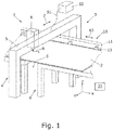
- Fig. 1 shows a processing machine 1 for the separating processing of a workpiece 2 in the form of a sheet metal, which has a laser cutting device 3 as a processing tool.
- the laser cutting device 3 has a portal-like guide structure 4 with a portal cross member 5 and a laser cutting head 6 guided on the portal cross member 5. In directions perpendicular to one another, the laser cutting head 6 is movable relative to the portal cross member 5 in the direction of double arrows 7, 8.
- the laser cutting head 6 is connected to a laser beam source in the form of a solid-state laser 52 via an optical fiber cable 51.
- the portal-like guide structure 4 overlaps a two-part workpiece table 9 on which a sheet metal 2 before, during and after the cutting machining is stored.
- the sheet metal 2 is processed in a separating manner.
- the sheet metal 2 is supported on the workpiece table 9. Slag formed during machining, as well as dust and smoke, are sucked off through a gap S formed between the two parts of the workpiece table 9 and a discharge device (eg a suction box, not shown) arranged below the gap S and connected to a fan.
- a discharge device eg a suction box, not shown
- workpiece parts that have been cut free by means of the laser cutting head 6 are separated from a residual workpiece (scrap lattice) also generated during machining and then removed from the vicinity of the machine tool 1.
- the sheet metal movement unit 10 comprises a rail 11 which is movably guided in the direction of a double arrow 12 by a guide device (not shown) and to which a sheet metal 2 can be fixed by means of clamping claws 13.
- the sheet metal 2 is positioned in the working area of the laser cutting head 6 for processing.
- the sheet metal 2 can be moved in the direction of the double arrow 12 by the workpiece moving unit 10. Processing movements that are superimposed on this are carried out by the laser cutting head 6 in the direction of the double arrow 7.
- the laser cutting head 6 has an additional axis which enables short, highly dynamic movements of the laser cutting head 6 in the direction of the double arrow 8 and thus in the direction of movement of the workpiece moving unit 10. With a final separating cut, the laser cutting head 6 makes an incision (in Fig. 1 not shown) workpiece part of the (in Fig. 1 not shown) scrap skeleton free.
- the workpiece part and the skeleton on the processing machine 1 are each in a processing position. After the machining has been completed, the workpiece moving unit 10 transfers the workpiece part that has now been cut free and the scrap skeleton together from the respective machining position into an unloading position.
- FIG Fig. 2 illustrated relationships, which a device 16 for removing the workpiece part 14 from the remaining workpiece 15 shows.
- a device 16 for removing the workpiece part 14 from the remaining workpiece 15 shows.
- Fig. 2 only a single workpiece part 14 on the processed sheet metal 2, which is enclosed by the remaining workpiece 15 (scrap lattice).
- the workpiece part 14 is removed from the remaining workpiece 15 by means of the device 16 before the workpiece part 14 can be transported away from the vicinity of the processing machine 1.
- the remaining workpiece 15 remains on the workpiece table 9 (cf. Fig. 1 ), before it is also removed from the vicinity of the processing machine 1 after all workpiece parts have been removed.
- a plate-like workpiece support 17 of the workpiece table 9 serves as workpiece support for the remaining workpiece 15 and the workpiece part 14 Fig. 2 bristles or rollers that cannot be seen are provided, which enable a low-friction and scratch-free movement of the processed sheet metal 2 over the stationary workpiece support 17.
- the support points of the processed sheet metal 2 on the bristles or the rollers of the workpiece support 17 define an in Fig. 2 Indicated support plane 18 of the workpiece support 17.
- the support plane 18 runs parallel to the main plane of the plate of the workpiece support 17. Along the support plane 18, the workpiece part 14 and the remaining workpiece 15 are aligned with one another.
- the workpiece support 17 of the processing machine 1 is designed as a perforated plate with a multiplicity of through openings 19 in the illustrated example.
- the workpiece support 17 can be formed by several profile bodies, which are spaced from one another in parallel with the formation of slot-shaped passage openings 19 and are arranged parallel to the gap S and have a brush element comprising several bundles of bristles on their end face facing the workpiece 2.
- a lifting unit 20 is arranged below the workpiece support 17, and a counter-holding unit 21 of the device 16 is arranged above the workpiece support 17.
- the lifting unit 20 comprises four identical lifting devices 22a-d, of which in FIG Fig. 2 a first and a second lifting device 22a, 22b can be seen, which Counter-holding unit 21 comprises four identical holding devices 24a-d, of which in FIG Fig. 2 a first and second holding device 24a, 24b can be seen.
- the lifting devices 22a-d can be moved parallel to the storage plane 18 by means of a lifting device moving device 26 and can basically be moved to any point below the workpiece support 17, whereby it must be ensured during the movement that the lifting devices 22a-d do not collide with one another and the Lifting elements 47 are placed under the passage openings 19.
- the first and second lifting devices 22a, 22b are arranged on a support structure in the form of a first longitudinal rail 27a of the lifting device moving device 26, along which the first and second lifting devices 22a, 22b can move in the Y direction of an XYZ coordinate system, driven by a motor.
- a drive motor 28 of the lifting devices 22a, 22b is shown in FIG Fig. 2 to recognize.
- the longitudinal rail 27a can be moved in the X direction on two transverse rails 29, 30 of the lifting device moving device 26 running perpendicular to the first longitudinal rail 27a.
- the third and fourth lifting devices 22c, 22d of the lifting device moving device 26 are arranged on a support structure in the form of a second longitudinal rail 27b, along which the third and fourth lifting devices 22c, 22d are motor-driven by means of a further drive motor, not shown in the figure can move in the Y direction.
- the transverse rails 29, 30 can be raised and lowered together with the two longitudinal rails 27a, 27b and the lifting devices 22a-d guided by them perpendicular to the workpiece support 17 or the storage plane 18 (in the Z direction).
- a holding device moving device 31 comprises a first longitudinal rail 32a, along which a first and second holding device 24a, 24b motor-driven can be moved and delivered in the Y-direction.
- the longitudinal rail 32a can be driven by a motor along two transverse rails 33, 34, which in turn run perpendicular to the first longitudinal rail 32a.
- third and fourth holding devices 24c, 24d (not shown) of the holding device moving device 31 are arranged on a support structure in the form of a second longitudinal rail 32b (not shown), along which the third and fourth holding devices 24c, 24d by means of another (not shown) Drive motor driven by a motor can move in the Y direction.
- the transverse rails 33, 34 can be raised and lowered together with the two longitudinal rails 32a, 32b and the holding devices 24a-d guided by them perpendicular to the workpiece support 17 or the storage plane 18 (in the Z direction).
- FIG Fig. 1 A numerical control unit 35 used for this purpose is shown in FIG Fig. 1 indicated.
- the coordinate axes of the numerical control of the processing machine 1 and the device 16 are shown in FIG Fig. 1 denoted by X, Y, Z.
- FIG. 2 The first and second lifting devices 22a, 22b shown have evidently Fig. 2 a lifting housing 46a, 46b, to which the first and second lifting devices 22a, 22b are connected to the first longitudinal rail 27a of the lifting device moving device 26.
- Third and fourth lifting devices 22c, 22d, which are not illustrated, are evidently shown Figures 3a-d also each have a lifting housing 46c, 46d to which the third and fourth lifting devices 22c, 22d are connected to the second longitudinal rail 27b of the lifting device moving device 26.
- a plurality of conventional pneumatic piston-cylinder units which are not shown in detail in the figures, are accommodated in the interior of a respective extraction housing 46a-d.
- a lifting element in the form of a lifting pin 47 is connected to each of the pistons.
- the piston-cylinder units in The interior of the lifting housings 46a-d can be controlled separately and can be connected independently of one another to a pressure source not shown in detail.
- the lifting pins 47 are extended in the vertical direction (Z direction) from the respective lifting housing 46a-d or moved back into the lifting housing 46a-d.
- the cross section of the lifting pins 47 is smaller than the cross section of the passage openings 19 on the workpiece support 17 (cf. Fig. 2 )
- the lifting pins 47 are arranged in a grid arrangement on a rectangular end face of the lifting housings 46a-d.
- the lifting housings 46a-d or the lifting devices 22a-d thus have a rectangular base area parallel to the storage plane 18 of the remaining workpiece 15.
- the method described below as an example is divided into the following steps: initial positioning, (iterative) global geometric positioning, (iterative) local geometric positioning, each with the resolution of collisions, optional evaluation of the excavation positions X Aa , Y Aa , ....
- a rectangular enclosing contour 36 (enclosing rectangle) enclosing the workpiece part 14 to be removed is first determined, the edges of which run parallel to the X direction or the Y direction.
- the number of lifting devices 22a-d required to remove the workpiece part 14 is then determined.
- a percentage of the overlap of the rectangular enclosing contour 36 with the lifting devices 22a-d or with the end faces of the lifting housings 46a-d can be used.
- the number of lifting devices 22a-d should be selected such that the percentage of overlap with lifting devices 22a-d exceeds a specified value of the surface area of the surrounding contour 36. As many of the lifting devices 22a-d are used as are required to cover the workpiece part 14, or as in the case of FIG Figures 3a-d large workpiece part 14 shown - as many as are available, ie all four lifting devices 22a-d.
- step b) the four lifting devices 22a-d are distributed collision-free and uniformly relative to the surrounding contour 36 of the workpiece part 14 to be removed, ie with the same distances A AB , A AC from one another and from the outer edges of the rectangular surrounding contour 36, as shown in FIG Fig. 3a is shown as an example.
- the (initial) lifting positions X Aai , Y Aai ; X Abi , Y Abi ; X Aci , Y Aci ; X Adi , Y Adi of the four lifting devices 22a-d set.
- the enclosing contour 36 is larger than the lifting devices 22a-d, as in the example shown, the initial positions X Aai , Y Aai ; X Abi , Y Abi ; X Aci , Y Aci ; X Adi , Y Adi of the lifting devices 22a-d within the enclosing contour 36.
- the initial lifting positions X Aai , Y Aai ; X Abi , Y Abi ; X Aci , Y Aci ; X Adi , Y Adi of the lifting devices 22a-d also lie outside the enclosing contour 36, so that there is only a partial overlap between the workpiece part 14 and the lifting devices 22a-d.
- the minimum distances between the lifting devices 22a-d must be observed, or the minimum distances between the lifting devices 22a-d and supporting structures, i.e. in the example shown the longitudinal rails 27a, b if the lifting devices 22a-d are offset from one another be positioned.
- the lifting devices are distributed in such a way that the initial lifting positions X Aai , Y Aai ; X Abi , Y Abi ; X Aci , Y Aci ; X Adi , Y Adi to the enclosing contour 36 have the same distances.
- the initial positioning of the lifting devices 22a-d therefore only depends on the surrounding rectangle 36 of the workpiece part 14 to be removed.
- a rectangular effective area 37 is determined for each of the four lifting devices 22a-d, as shown in FIG Figure 3b is shown as an example for the first lifting device 22a.
- the rectangular effective area 37 of the first lifting device 22a is delimited by the rectangular enclosing contour 36, by the second lifting device 22b adjacent in the Y direction and by the third lifting device 22c adjacent in the X direction. Due to the uniform distribution of the lifting devices 22a-d in step b), the lifting position X Aai , Y Aai of the first lifting device 22a forms the center of the rectangular active area 37 in the example shown.
- a subsequent step d) the lifting positions X Aa , Y Aa ; X Ab , Y Ab ; X Ac , Y Ac ; X Ad , Y Ad of the lifting devices 22a-d are set again, taking into account the respective effective range 37.
- the lifting position X Aa , Y Aa of the first lifting device 22a is determined again on the basis of a sub-area 38 of the workpiece part 14 to be removed, which lies within the effective area 37 of the first lifting device 22a and the in Figure 3b is shown with double hatching.
- the sub-area 38 which lies in the effective area 37, in which in FIG Figure 3b shown example on two non-interconnected partial areas.
- the lifting position X Aa , Y Aa of the first lifting device 22a is determined on the basis of a geometric property of the partial area 38 of the workpiece part 14 positioned in the effective area 37.
- the geometric property is the centroid X s , Y s of the sub-area 38, ie the newly defined lifting position X Aa , Y Aa corresponds to the centroid X s , Y s of the sub-area 38.
- the lifting positions X Ab , Y Ab , X Ac , Y Ac , X Ad , Y Ad of the three other lifting devices 22b-d If no partial area 38 of the workpiece part 14 is contained in the effective area 37, the previously determined initial position X Aai , Y Aai of the first lifting device 22a remains unchanged.
- the (global) positioning of the lifting devices 22a-d ends with step d), ie the lifting devices 22a-d are attached to the in step d) defined lifting positions X Aa , Y Aa ; X Ab , Y Ab ; X Ac , Y Ac : X Ad , Y Ad positioned from the initial lifting positions X Aai , Y Aai ; X Abi , Y Abi ; X Aci , Y Aci ; X Adi , Y Adi usually differ, as shown in Figure 3b for the first lifting device 22a is shown.
- the common X coordinate of the lifting positions of the first and second lifting devices 22a, 22b in each case the mean value 1/2 (X Aa + X Ab ) of the two X coordinates of the X coordinates of the lifting positions X Aa and X Ab determined in the manner described above are used.
- the third and fourth lifting devices 22c, 22d which are also mounted on a common longitudinal rail 27b, are handled accordingly.
- step d) a step e) is carried out one after the other for each of the four lifting devices 22a-d, which is carried out on the basis of the first lifting device 22a in connection with Figure 3c is described:
- step e) a distance A AB between the first lifting device 22a and the second lifting device 22b adjacent in the Y direction is first determined and compared with a minimum distance A YM that the lifting devices 22a-d should maintain from one another in the Y direction.
- the first lifting device 22a or the Y coordinate of the lifting position Y Aa is moved in the positive Y direction (ie in Figure 3c up) and the Y coordinate of the lifting position Y Ab of the second lifting device 22b is used in the negative Y direction (i.e. in Figure 3c down) until the minimum distance A YM in the Y direction is observed.
- the procedure for the X coordinate is the same: In the event that the first lifting device 22a has a distance A AC from the third lifting device 22c that is smaller than a minimum distance A XM that the lifting devices 22a-d should maintain from one another in the X direction , the X coordinate of the lifting position X Aa of the first lifting device 22a in the negative X direction (in Figure 3c to the left) and the X coordinate of the lifting position X Ac of the third lifting device 22c is changed accordingly in the positive X direction (in Figure 3c to the right) changed by the same amount until the minimum distance A XM in the X direction is observed.
- a grid of the workpiece support 17 can be taken into account if this has passage openings 19 for the lifting elements 47 of the lifting devices 22a-d. Since the lifting elements 47 of the lifting devices 22a-d have to be placed under the passage openings 19, the positioning of the lifting devices 22a-d cannot take place continuously, but only in discrete steps that correspond to the grid of the passage openings 19.
- the procedure is similar until the respective distances A AB , A AC , A CD , A BD of all four lifting devices 22a-d are greater than the minimum distances A XM , A YM .
- the change in the lifting positions of two adjacent lifting devices 22a, 22b in order to maintain the minimum distance A XM or A YM can lead to secondary collisions: for example, when the second lifting device is moved 22b to the right, the minimum distance A XM to a third lifting device adjacent to the right is not reached.
- Such subsequent collisions are further resolved iteratively in the direction of the displacement, i.e.
- the second lifting device 22b or the X coordinate of the second lifting position X Ab is pushed to the right, it also pushes all other lifting devices with which it would collide to the right in front of it . If there is an edge when the (subsequent) collisions are resolved or a stop of the movability is reached, the direction of release must be reversed, ie the lifting devices are shifted to the left. In the case of a lifting device that does not maintain the minimum distance A XM to the left and right in the X direction, for example, the two lifting devices adjacent to the left and right are moved away from the central lifting device until the specified minimum distances A XM left and right are observed. In the same way, if the lifting devices 22a-d are offset ("meshing") with one another in the Y direction, a collision check and rectification can take place between the lifting devices 22a-d and the respectively adjacent longitudinal rail 27a, b.
- step e) If in step e) the lifting positions X Aa , Y Aa ; X Ab , Y Ab ; X Ac , Y Ac ; X Ad , Y Ad of the lifting devices 22a-d changed, the corresponding active areas 37 also change, ie the lifting devices 22a-d may no longer be optimally positioned for removing the workpiece part 14 from the remaining workpiece 15. Therefore, steps c), d) and e) described above are usually repeated until a termination criterion is reached.
- the termination criterion can be a predetermined number of repetitions or iterations. Since with such a termination criterion it is not ensured that the workpiece part 14 can be removed from the remaining workpiece 15 in a process-reliable manner, it is advantageous if another termination criterion is selected.
- Such a termination criterion consists of a measure for the change in the defined lifting positions X Aa , Y Aa ; X Ab , Y Ab ; X Ac , Y Ac : X Ad , Y Ad when performing steps d) and e). If there are no significant changes in the lifting positions X Aa , Y Aa ; X Ab , Y Ab ; X Ac , Y Ac ; X Ad , Y Ad more, it can be assumed that an (approximately) optimal, process-reliable arrangement of the lifting devices 22a-d for removing the workpiece part 14 from the remaining workpiece 15 has been found.
- X Aa , Y Aa ; X Ab , Y Ab ; X Ac , Y Ac ; X Ad , Y Ad can, for example, be the largest (geometric) distance between the respective lifting positions X Aa , Y Aa ; X Ab , Y Ab ; X Ac , Y Ac ; X Ad , Y Ad serve before and after performing steps d) and e).
- an evaluation criterion or an evaluation function can be used as the termination criterion with which the suitability of the lifting positions X Aa , Y Aa ; ... is evaluated for the removal of the workpiece part 14 from the remaining workpiece 15.
- the evaluation criterion typically includes the determination of the number of active digging pins 47, ie those digging pins 47 that are shown in Figures 3a-c are shown in dashed lines because they are arranged under the workpiece part 14 and are therefore covered by this. The greater the number of active lifting pins 47, the better the support of the workpiece part 14 during removal is typically.
- the area of the convex envelope that is spanned by the active excavation pins 47 can also serve as an evaluation criterion.
- the area of the convex envelope like the number of active digging pins 47, should be as large as possible.
- Another evaluation criterion is the ratio of the compressive force p of all active lifting elements 47 to the weight g of the workpiece part (cf. Fig. 1 ).
- the maximum of all distances between any points on the workpiece part 14 and a respective closest active lifting element 47 can also serve as an evaluation criterion.
- the deflection of the workpiece part 14 when it is placed on the active lifting pins 47 of the lifting devices 22a-d can also serve as an evaluation criterion. Finite element methods can be used to calculate the deflection of the workpiece part 14. In addition, possible tilting and hooking of the workpiece part 14 in the remaining workpiece 15 can also be recognized with such calculations.
- the individual evaluation criteria or modules can be selectable by an operator of the device 16 or the processing machine 1 or by the programming system for creating the processing program for the machine 1, depending on a desired degree of optimization, calculation effort or the complexity of the workpiece parts 14 to be removed can be set algorithmically.
- the determined value of the evaluation criterion is compared with a threshold value which must be exceeded or fallen below in order to terminate the method.
- the threshold value can, for example, have a predetermined number of active ones Lifting pins 47, a predetermined ratio of the area of the convex envelope, which is spanned by the active lifting pins 47, to the area of the workpiece part 14, a predetermined ratio of compressive force p to weight g of workpiece part 14, etc. form.
- the method described above can be used with smaller, local effective areas 37a (cf. Fig. 3d ) of the lifting devices 22a-d can be carried out again until a respective termination criterion is met.
- the smaller effective areas 37a ensure that local optimization takes place.
- the lifting positions of the lifting devices 22a-d are set again with the aid of a (in Fig. 3d double hatched) partial area 38 of the workpiece part 14, which lies within the (smaller) local effective area 37a.
- the local effective area 37a has dimensions, ie a length and a width, which the dimensions (length and width) of the (first) excavation device 22a, more precisely the rectangular end face of the first excavation housing 46a, by at least 10%, but typically not exceed more than 50%.
- the center point of the local effective area 37a and the center point of the first lifting device 22a coincide in the example shown.
- the local effective area 37a can in particular be defined independently of the positioning of the other lifting devices 22b-d and the enclosing contour 36.
- steps c), d) and e) and, if applicable, the evaluation of the lifting positions X Aa , Y Aa, ..., X Ad , Y Ad after a predetermined number of repetitions or iterations can be based on the above in Connection with the (global) positioning.
- Fig. 4 shows an example of a counter-holding unit 21 which, instead of the counter-holding unit 21 described above, has six holding devices 24a-f instead of four, of which three holding devices 24a-c on a longitudinal rail 32a and three holding devices 24d-f on a further longitudinal rail 32b are attached.
- the holding devices 24a-c, 24d-f arranged on a common longitudinal rail 32a, b can be moved independently of one another in the Y direction.
- the longitudinal rails 32a, b can be moved independently of one another in the X direction. The movement always takes place parallel to the bearing plane 18.
- the holding positions X Ha, Y Ha , ..., X Hf , Y Hf of the in Fig. 4 The six holding devices 24a-f shown of the counter-holding unit 21 are determined analogously to the lifting positions X Aa , Y Aa ,..., X Ad , Y Ad of the lifting devices 22a-d, ie to those in connection with Figures 3a-d described way.
- the holding devices 24a-f each have a box-shaped housing 48a, 48b, ... with an in Fig. 4 to be recognized, rectangular planar contact plate 49, which is provided with a plurality of bores in a grid-shaped arrangement.
- the bores receive holding elements in the form of suction grippers 50, which have suction sleeves that are elastically deformable perpendicular to the contact plate 49 in order to suck the workpiece part 14 when it is removed from the remaining workpiece 15.
- the holding positions X Ha, Y Ha , ..., X Hf , Y Hf can be evaluated with the aid of one or more evaluation criteria, the For example, the following are selected from the group: number of active holding elements 50 of holding devices 24a-f, area of the convex envelope that is spanned by active holding elements 50, ratio of holding force h (cf. Fig.
- the maximum distance between all points of the workpiece part 14 and the closest active holding element 50, as well as deflection of the workpiece part 14 when it is held on the active holding elements 50 can be done with the help of finite element methods.
- a less complex evaluation criterion is the ratio between the holding force h of all active holding elements 50 of the holding devices 24a-f that suck the workpiece part 14 during removal to the weight g of the workpiece part 14. If the load-bearing or holding force of all holding elements 50 is a predetermined factor or the threshold value above the weight of the workpiece part 14 to be removed, the workpiece part 14 can be held reliably by the holding devices 24a-f during removal. Exceeding this threshold value can serve as a termination criterion in the (iterative) definition of the stop positions X Ha, Y Ha , ..., X Hf , Y Hf of the holding devices 24a-f.
- Fig. 2 the process of removing the workpiece part 14 from the remaining workpiece 15 is described, which takes place after the lifting positions X Aa , Y Aa, ... and the holding positions X Ha , Y Ha , ... have been defined.
- the processed sheet metal 2 and the workpiece support 17 are positioned relative to one another in such a way that the workpiece part 14 covers a sufficient number of passage openings 19 of the workpiece support 17.
- the sheet metal moving unit 10 functions as an adjusting device, by means of which the processed sheet metal 2 with the workpiece part 14 and the remaining workpiece 15 can be fed to the processing machine 1 in the X direction of the coordinate system.
- the lifting device moving device 26 below the workpiece support 17 is actuated numerically in such a way that the lifting devices 22a-d move to the lifting positions X Aa , Y Aa, ..., X Ad , Y Ad below the workpiece part 14, defined in the manner described above .
- the holding devices 24a-d on the opposite side of the workpiece support 17 are moved into the holding positions X Ha, Y Ha , ..., X Hd , Y Hd above by numerically controlled actuation of the holding device moving device 31 of the workpiece part 14 located in the unloading position.
- the holding devices 22a-d are then lowered by a corresponding vertical movement of the holding device moving device 31 and thereby placed on the processed sheet metal 2 or on the workpiece part 14 and the remaining workpiece 15.
- the suction sleeves of the suction grippers 50 are compressed and consequently folded more strongly and pushed back into the interior of the bores on the contact plate 49 of the holding devices 24a-d until the contact plates 49 of the holding devices 24a-d finally touch the sheet metal surface.
- a control signal from the control device 35 causes the lifting pins 47 of the lifting devices 22a-d to push the workpiece part 14 out of the remaining workpiece 15 in a removal direction (Z direction) and at the same time the holding devices 24a-d using the holding device movement device 31 synchronously in the removal direction Z be moved.
- the workpiece part 14 initially arranged in the plane of the remaining workpiece 15 is lifted or removed from the remaining workpiece 15.
- the vacuum generator of the holding devices 24a-d is switched on. As a result, the workpiece part 14 is fixed or fixed on the holding devices 24a-d.
- the lifting pins 47 which previously acted on the workpiece part 14, are withdrawn into the lifting housing 46a-d of the lifting devices 22a-d.
- the holding devices 24a-d then move with the workpiece part 14 fixed thereon with the aid of the holding device moving device 31 from the vicinity of the workpiece support 17 50, which hold the workpiece part 14, switched to depressurized.
- the mode of operation of the removal device 16 has been described above on the basis of a processing machine 1 with a combined movement of the workpiece 2 and the laser cutting head 6.
- the removal device 16 can, however, also be used in an analogous manner on a processing machine in which the workpiece rests during processing and is arranged, for example, on a web support that can be moved into and out of the processing area of the machine with the aid of a pallet changer.
- the removal device 16 is used to automate such a flying optics machine, this is also possible without an additional lifting device.
- the holding devices 24a-d are in this case first placed on the surface of the workpiece part 14 and then the vacuum generator of the holding devices 24a-d is switched on. The holding devices 24a-d are thereby transferred from a released state into a fixing state in which the workpiece part 14 is fixed or fixed on the holding devices 24a-d.
- the holding elements 50 can be designed, for example, as active suction devices, the opening state of which can be changed by means of a control.
- a contact plate 49 is not necessary in this example.
Landscapes
- Engineering & Computer Science (AREA)
- Mechanical Engineering (AREA)
- Physics & Mathematics (AREA)
- Optics & Photonics (AREA)
- Life Sciences & Earth Sciences (AREA)
- Forests & Forestry (AREA)
- Plasma & Fusion (AREA)
- Agronomy & Crop Science (AREA)
- Jigs For Machine Tools (AREA)
- Feeding Of Workpieces (AREA)
- Manipulator (AREA)
- Laser Beam Processing (AREA)
Claims (20)
- Procédé pour la définition de positions de soulèvement (XAa, YAa, ...) d'au moins deux dispositifs de soulèvement (22a-d) comprenant chacun une pluralité d'éléments de soulèvement (47) et/ou de positions de retenue (XHa, YHa, ...) d'au moins deux dispositifs de retenue (24a-f) comprenant chacun une pluralité d'éléments de retenue (50) pour le retrait d'une partie de pièce (14) d'une pièce restante (15), les dispositifs de soulèvement (22a-d) et/ou les dispositifs de retenue (24a-f) pouvant être déplacés parallèlement à un plan de montage (18) de la partie de pièce (14) à retirer de la pièce restante (15), caractérisé par les étapes suivantes :a) la détermination d'un contour d'entourage (36), notamment rectangulaire, entourant la partie de pièce à retirer (14),b) la définition initiale de positions de soulèvement (XAa, YAa, ...) d'au moins deux des dispositifs de soulèvement (22a-d) et/ou de positions de retenue (XHa, YHa, ...) d'au moins d'au moins deux des dispositifs de retenue (24a-d) par rapport au contour d'entourage (36),c) la définition d'une zone de travail (37, 37a) pour chacun des dispositifs de soulèvement (22a-d) à leur position de soulèvement définie respectivement (XAa, YAa, ...) et/ou pour chacun des dispositifs de retenue (24a-f) à leur position de retenue définie respectivement (XHa, YHa,...), ainsi qued) la nouvelle définition des positions de soulèvement (XAa, YAa,...) des dispositifs de soulèvement (22a-d) et/ou des positions de retenue (XHa, YHa,...) des dispositifs de retenue (24a-d) sur la base d'une zone partielle (38) de la partie de pièce à retirer (14) positionnée dans la zone de travail respective (37, 37a) .
- Procédé selon la revendication 1, dans lequel, dans l'étape a), les positions de soulèvement (XAa, YAa, ...) et/ou les positions de retenue (XHa, YHa,...) sont définies initialement avec des écarts identiques par rapport au contour d'entourage (36).
- Procédé selon la revendication 1 ou 2, dans lequel, dans l'étape c), la définition des positions de soulèvement (XAa, YAa,...) et/ou des positions de retenue (XHa, YHa,...) a lieu sur la base d'au moins une propriété géométrique de la zone partielle (38) de la partie de pièce (14) se trouvant dans la zone de travail respective (37, 37a), la propriété géométrique étant de préférence un centroïde (Xs, Ys) de la zone partielle (38).
- Procédé selon la revendication 3, dans lequel la position de soulèvement (XAa, YAa,...) et/ou la position de retenue (XHa, YHa,...) d'un dispositif de soulèvement (22a-d) et/ou d'un dispositif de retenue (24a-d) est définie en concordance avec le centroïde (Xs, Ys) de la zone partielle (38) de la partie de pièce (14) se trouvant dans la zone de travail respective (37, 37a).
- Procédé selon l'une quelconque des revendications précédentes, dans lequel, après l'étape d), l'étape suivante est réalisée successivement pour chaque dispositif de soulèvement (22a-d) et/ou pour chaque dispositif de retenue (24a-f) :e) la détermination d'au moins un écart (AAB, AAC) du dispositif de soulèvement (22a) par rapport au(x) dispositif(s) de soulèvement voisin(s) (22b-d) et/ou du dispositif de retenue (24a) par rapport (au)x dispositif(s) de retenue voisin(s) (24b-d), ainsi que, dans le cas où l'écart (AAB, AAC, AAD, AAE, AAF) est inférieur à un écart minimal (AYM, AXM),la modification de la position de soulèvement définie (XAa, YAa) du dispositif de soulèvement (22a) et/ou de la ou des position(s) de soulèvement définie(s) (XAb, YAb, ...) du ou des dispositif (s) de soulèvement voisin(s) (22b-d) et/oula modification de la position de retenue définie (XHa, YHa) du dispositif de retenue (24a) et/ou de la ou des position (s) de retenue définie (s) (XHb, YHb,...) du ou des dispositif(s) de retenue voisin(s) (24b-f), jusqu'à ce que l'écart minimal (AYM, AXM)soit atteint.
- Procédé selon l'une quelconque des revendications précédentes, dans lequel la définition et/ou la modification de positions de soulèvement (XAa, YAa,...) des dispositifs de soulèvement (22a-d) a lieu en étapes discrètes, afin de prendre en compte des ouvertures de passage (19) d'un support de pièce (17) pour le passage d'éléments de soulèvement (47) des dispositifs de soulèvement (22a-d).
- Procédé selon la revendication 5 ou 6, dans lequel les étapes c), d) et e) sont répétées jusqu'à ce qu'un critère de terminaison soit atteint.
- Procédé selon la revendication 7, dans lequel une mesure pour la modification des positions de soulèvement définies (XAa, YAa,...) et/ou des positions de retenue définies (XHa, YHa, ...) dans l'étape d) et/ou dans l'étape e) forme le critère de terminaison.
- Procédé selon la revendication 8, dans lequel, après un nombre prédéterminé de répétitions, les positions de soulèvement définies (XAa, YAa,...) et/ou les positions de retenue définies (XHa, YHa,...) sont évaluées avec un critère d'évaluation, le critère d'évaluation étant de préférence utilisé en tant que critère de terminaison.
- Procédé selon la revendication 9, dans lequel le critère d'évaluation pour les positions de soulèvement (XAa, YAa,...) est choisi ou peut être choisi dans le groupe comprenant : le nombre d'éléments de soulèvement actifs (47) des dispositifs de soulèvement (22a-d), la surface de l'enveloppe convexe qui est engendrée par les éléments de soulèvement actifs (47), le rapport de la force de pression (p) des éléments de soulèvement actifs (47) au poids (g) de la partie de pièce (14), l'écart maximal de tous les points quelconques de la partie de pièce (14) par rapport à un élément de soulèvement actif respectivement le plus proche (47), le fléchissement de la partie de pièce (14) lorsqu'elle est posée sur les éléments de soulèvement actifs (47) des dispositifs de soulèvement (22a-d).
- Procédé selon la revendication 9 ou 10, dans lequel le critère d'évaluation pour les positions de retenue (XHa, YHa,...) est choisi ou peut être choisi dans le groupe comprenant : le nombre d'éléments de retenue actifs (50) des dispositifs de retenue (24a-f), la surface de l'enveloppe convexe qui est engendrée par les éléments de retenue actifs (50), le rapport de la force de retenue (h) des éléments de retenue actifs (50) au poids (g) de la partie de pièce (14), l'écart maximal de tous les points quelconques de la partie de pièce (14) par rapport à un élément de retenue actif respectivement le plus proche (50), le fléchissement de la partie de pièce (14) lorsqu'elle est retenue sur les éléments de retenue actifs (50).
- Procédé selon l'une quelconque des revendications précédentes, dans lequel, dans l'étape c), une zone de travail (37, 37a) d'un dispositif de soulèvement respectif (22a) est définie, qui est délimitée par le contour d'entourage (36) et au moins un dispositif de soulèvement voisin (22b, 22c) et/ou dans lequel, dans l'étape c), une zone de travail (37, 37a) d'un dispositif de retenue respectif (24a) est définie, qui est délimitée par le contour d'entourage (36) et au moins un dispositif de retenue voisin (24b, 24c).
- Procédé selon la revendication 12, dans lequel, lorsque le critère de terminaison a été atteint, une zone de travail locale plus petite (37a) pour chacun des dispositifs de soulèvement (22a-d) et/ou pour chacun des dispositifs de retenue (24a-f) est définie, les étapes c), d) et e) étant de nouveau réalisées une ou plusieurs fois jusqu'à ce qu'un critère de terminaison soit atteint.
- Procédé selon la revendication 13, dans lequel la zone de travail locale (37a) présente des dimensions qui dépassent les dimensions du dispositif de soulèvement (22a) et/ou du dispositif de retenue (24a) d'au moins 10 % et pas de plus de 50 %.
- Procédé selon l'une quelconque des revendications précédentes, dans lequel au moins deux des dispositifs de soulèvement (22a,b ; 22c,d) et/ou au moins deux des dispositifs de retenue (24a-f) sont couplés en déplacement par une structure porteuse commune (27a, 27b) dans une direction de déplacement (X) lors du déplacement parallèlement au plan de montage (18).
- Procédé selon l'une quelconque des revendications précédentes, dans lequel, dans une étape précédant l'étape b), le nombre de dispositifs de soulèvement (22a-d) et/ou de dispositifs de retenue (24a-f) nécessaires pour le retrait de la partie de pièce (14) est déterminé.
- Procédé selon l'une quelconque des revendications précédentes, dans lequel la partie de pièce (14) est reçue entre les au moins deux dispositifs de soulèvement (22a-d) agencés aux positions de soulèvement (XAa, YAa,...) et les au moins deux dispositifs de retenue (24a-f) agencés aux positions de retenue (XHa, YHa,...) pendant au moins une partie du retrait de la pièce restante (15).
- Produit programme informatique, qui est configuré pour la réalisation de toutes les étapes du procédé selon l'une quelconque des revendications précédentes lorsque le programme informatique est exécuté sur une installation de traitement de données.
- Dispositif pour le retrait d'une partie de pièce (14) d'une pièce restante (15), comprenant :une unité de soulèvement (20) munie d'au moins deux dispositifs de soulèvement (22a-d), qui comprennent chacun une pluralité d'éléments de soulèvement (47), ainsi queune unité de contre-appui (21) munie d'au moins deux dispositifs de retenue (24a-f), qui comprennent chacun une pluralité d'éléments de retenue (50),un appareil de déplacement de dispositif de soulèvement (26) pour le déplacement des dispositifs de soulèvement (22a-d) parallèlement à un plan de montage (18) de la pièce restante (15),un appareil de déplacement de dispositif de retenue (31) pour le déplacement des dispositifs de retenue (24a-f) parallèlement au plan de montage (18) de la pièce restante (15),caractérisé par une unité de commande (35) pour la commande de l'appareil de déplacement de dispositif de soulèvement (26) pour le déplacement des dispositifs de soulèvement (22a-d) à des positions de soulèvement définies (XAa, YAa,...) et pour la commande de l'appareil de déplacement de dispositif de retenue (31) pour le déplacement des dispositifs de retenue (24a-d) à des positions de retenue définies (XHa, YHa,...), l'unité de commande (35) étant configurée pour définir les positions de soulèvement (XAa, YAa,...) et/ou les positions de retenue (XHa, YHa,...) selon un procédé qui comprend les étapes suivantes :a) la détermination d'un contour d'entourage (36), notamment rectangulaire, entourant la partie de pièce à retirer (14),b) la définition initiale de positions de soulèvement (XAa, YAa,...) d'au moins deux des dispositifs de soulèvement (22a-d) et/ou de positions de retenue (XHa, YHa,...) d'au moins deux des dispositifs de retenue (24a-d) par rapport au contour d'entourage (36),c) la définition d'une zone de travail (37, 37a) pour chacun des dispositifs de soulèvement (22a-d) à leur position de soulèvement définie respectivement (XAa, YAa,...) et/ou pour chacun des dispositifs de retenue (24a-f) à leur position de retenue définie respectivement (XHa, YHa,...), ainsi qued) la nouvelle définition des positions de soulèvement (XAa, YAa,...) des dispositifs de soulèvement (22a-d) et/ou des positions de retenue (XHa, YHa,...) des dispositifs de retenue (24a-d) sur la base d'une zone partielle (38) de la partie de pièce à retirer (14) positionnée dans la zone de travail respective (37, 37a) .
- Machine d'usinage (1) pour l'usinage de séparation de pièces en forme de plaques (15), notamment de tôles, au moyen d'un outil d'usinage (3), comprenant en outre : un dispositif (16) selon la revendication 19 pour retirer une partie de pièce (14) séparée d'une pièce restante (15) lors de l'usinage de séparation.
Priority Applications (1)
| Application Number | Priority Date | Filing Date | Title |
|---|---|---|---|
| PL18759097T PL3684545T3 (pl) | 2017-09-22 | 2018-08-22 | Sposób ustalania pozycji wydobywczych i/lub pozycji przytrzymywania, urządzenie do usuwania części przedmiotu poddawanego obróbce oraz obrabiarka |
Applications Claiming Priority (2)
| Application Number | Priority Date | Filing Date | Title |
|---|---|---|---|
| DE102017216828.5A DE102017216828B4 (de) | 2017-09-22 | 2017-09-22 | Verfahren zum Festlegen von Aushebepositionen und/oder von Haltepositionen, Vorrichtung zum Entnehmen eines Werkstückteils und Bearbeitungsmaschine |
| PCT/EP2018/072649 WO2019057432A1 (fr) | 2017-09-22 | 2018-08-22 | Procédé destiné à définir des positions de retrait et/ou des positions de retenue, dispositif destiné à retirer une partie de pièce et machine d'usinage |
Publications (2)
| Publication Number | Publication Date |
|---|---|
| EP3684545A1 EP3684545A1 (fr) | 2020-07-29 |
| EP3684545B1 true EP3684545B1 (fr) | 2021-11-03 |
Family
ID=63350550
Family Applications (1)
| Application Number | Title | Priority Date | Filing Date |
|---|---|---|---|
| EP18759097.1A Active EP3684545B1 (fr) | 2017-09-22 | 2018-08-22 | Procédé destiné à définir des positions de retrait et/ou des positions de retenue, dispositif destiné à retirer une partie de pièce et machine d'usinage |
Country Status (5)
| Country | Link |
|---|---|
| EP (1) | EP3684545B1 (fr) |
| CN (1) | CN111132795B (fr) |
| DE (1) | DE102017216828B4 (fr) |
| PL (1) | PL3684545T3 (fr) |
| WO (1) | WO2019057432A1 (fr) |
Families Citing this family (3)
| Publication number | Priority date | Publication date | Assignee | Title |
|---|---|---|---|---|
| DE102019209923B4 (de) * | 2019-07-05 | 2025-05-22 | TRUMPF Werkzeugmaschinen SE + Co. KG | Verfahren zum Transportieren von Werkstückteilen |
| CN113073455B (zh) * | 2021-04-13 | 2022-09-13 | 湖北嘉扬制衣有限公司 | 一种服饰面料裁切加工方法 |
| DE102021118252A1 (de) | 2021-07-14 | 2023-01-19 | Trumpf Werkzeugmaschinen Gmbh + Co. Kg | Verfahren zum Festlegen von Haltepositionen unter der Berücksichtigung von Niederhalteaspekten zur Entnahme eines Werkstückteils |
Family Cites Families (10)
| Publication number | Priority date | Publication date | Assignee | Title |
|---|---|---|---|---|
| JPH04187333A (ja) * | 1990-11-20 | 1992-07-06 | Amada Co Ltd | 板材加工装置の分離板材取出し装置 |
| JPH0930649A (ja) | 1995-07-13 | 1997-02-04 | Mitsubishi Electric Corp | ピックアップ装置 |
| ATE490839T1 (de) * | 2006-05-24 | 2010-12-15 | Trumpf Werkzeugmaschinen Gmbh | Verfahren zur optimierung einer anordnung von tragpunktspitzen an auflageelementen einer werkstückauflage unter verwendung von daten einer schachtelung von gut- und restteilen |
| EP2177293B1 (fr) | 2008-10-17 | 2013-01-02 | TRUMPF Werkzeugmaschinen GmbH + Co. KG | Procédé d'extraction d'une partie d'une pièce à usiner et machine-outil |
| CN103042639B (zh) * | 2012-12-19 | 2015-02-25 | 杭州欧亚环保工程有限公司 | 植物纤维模塑制品自动切边方法及自动切边机 |
| CN103191982B (zh) * | 2013-04-26 | 2014-10-22 | 上海元禾汽车零件有限公司 | 一种模具共用支撑装置 |
| DE102014209811B4 (de) * | 2014-05-22 | 2016-07-28 | J. Schmalz Gmbh | Vorrichtung zum gegenseitigen Trennen zweier Werkstückteile eines plattenartigen Werkstücks |
| US9629419B2 (en) * | 2014-07-28 | 2017-04-25 | Nike, Inc. | Pin plate for construction of an article |
| PL3106241T3 (pl) * | 2015-06-19 | 2018-01-31 | Trumpf Werkzeugmaschinen Gmbh Co Kg | Obrabiarka oraz sposób odprowadzania części przedmiotu obrabianego |
| DE102015223062B3 (de) | 2015-11-23 | 2017-02-09 | Trumpf Werkzeugmaschinen Gmbh + Co. Kg | Verfahren und Vorrichtungen zum Bewegen und/oder Entladen eines Werkstückausschnitts |
-
2017
- 2017-09-22 DE DE102017216828.5A patent/DE102017216828B4/de not_active Expired - Fee Related
-
2018
- 2018-08-22 PL PL18759097T patent/PL3684545T3/pl unknown
- 2018-08-22 EP EP18759097.1A patent/EP3684545B1/fr active Active
- 2018-08-22 WO PCT/EP2018/072649 patent/WO2019057432A1/fr not_active Ceased
- 2018-08-22 CN CN201880061563.8A patent/CN111132795B/zh active Active
Also Published As
| Publication number | Publication date |
|---|---|
| CN111132795B (zh) | 2022-08-09 |
| PL3684545T3 (pl) | 2022-02-28 |
| DE102017216828B4 (de) | 2019-05-09 |
| CN111132795A (zh) | 2020-05-08 |
| EP3684545A1 (fr) | 2020-07-29 |
| DE102017216828A1 (de) | 2019-03-28 |
| WO2019057432A1 (fr) | 2019-03-28 |
Similar Documents
| Publication | Publication Date | Title |
|---|---|---|
| EP3852984B1 (fr) | Procédé et dispositif pour prélever une partie de pièce sur une pièce restante | |
| EP3145656B1 (fr) | Dispositif pour séparer l'un de l'autre deux éléments d'une pièce en forme de plaque | |
| EP3106241B1 (fr) | Machine-outil et procédé destinés a l'évacuation de parties d'une pièce à usiner | |
| EP2177293B1 (fr) | Procédé d'extraction d'une partie d'une pièce à usiner et machine-outil | |
| DE102010042561B3 (de) | Verfahren zum Trennen von Gutteilen und Restgitter beim Laserschneiden einer Blechtafel | |
| EP2177289B1 (fr) | Machines-outils et procédé destinés à l'évacuation d'une partie d'une pièce à usiner | |
| DE102016110542B4 (de) | Be- und Entladevorrichtung für eine Maschine, Maschine zum Bearbeiten von plattenförmigen Werkstücken sowie Werkstückauflage für eine solche Maschine und Verfahren zum Be- und Entladen einer solchen Maschine | |
| EP2766147A1 (fr) | Procédé de production de pièces en un matériau en forme de plaque | |
| DE102013226818A1 (de) | Maschine zum trennenden Bearbeiten von plattenförmigen Werkstücken | |
| EP4076832B1 (fr) | Procédé de traitement de séparation d'une pièce et produit de programme logiciel | |
| EP3310524B1 (fr) | Procédé pour décharger en temps masqué une partie de pièce dégagée par découpe, machine de découpe au laser associée et produit-programme informatique associé | |
| EP4225526A1 (fr) | Procédé et machine pour couper et retirer des parties de pièces dans un matériau en forme de plaque | |
| DE102017216828B4 (de) | Verfahren zum Festlegen von Aushebepositionen und/oder von Haltepositionen, Vorrichtung zum Entnehmen eines Werkstückteils und Bearbeitungsmaschine | |
| EP1683601B1 (fr) | Méthode de découpage laser de tôles brutes et dispositif de découpe laser pour mettre en oeuvre ce procédé | |
| EP2177291A1 (fr) | Procédé de découpe et/ou formage de pièces et machine-outil | |
| EP2184116A1 (fr) | Procédé destiné à évacuer des éléments en tôle de machines de poinçonnage | |
| EP3993946B1 (fr) | Procédé de transport de parties de pièce ouvrée | |
| EP3727768B1 (fr) | Procédé permettant de soulever une pièce métallique en forme de plaque ainsi que dispositif de chargement et/ou de déchargement | |
| WO2018055178A1 (fr) | Procédé et machine-outil servant à l'usinage de pièces en forme de plaque, en particulier de tôles | |
| DE102018203061A1 (de) | Verfahren zum Auffinden einer geeigneten Halteposition | |
| DE3723743A1 (de) | Verfahren zur entsorgung von blech-trennmaschinen und zugehoerige anlage | |
| WO2017000989A1 (fr) | Outil pour poinçonneuse et procédé d'usinage d'une face frontale d'une pièce en forme de plaque | |
| DE102021118252A1 (de) | Verfahren zum Festlegen von Haltepositionen unter der Berücksichtigung von Niederhalteaspekten zur Entnahme eines Werkstückteils | |
| DE102023114159A1 (de) | Maschine sowie verfahren zum laserschneiden eines plattenförmigen werkstücks |
Legal Events
| Date | Code | Title | Description |
|---|---|---|---|
| STAA | Information on the status of an ep patent application or granted ep patent |
Free format text: STATUS: UNKNOWN |
|
| STAA | Information on the status of an ep patent application or granted ep patent |
Free format text: STATUS: THE INTERNATIONAL PUBLICATION HAS BEEN MADE |
|
| PUAI | Public reference made under article 153(3) epc to a published international application that has entered the european phase |
Free format text: ORIGINAL CODE: 0009012 |
|
| STAA | Information on the status of an ep patent application or granted ep patent |
Free format text: STATUS: REQUEST FOR EXAMINATION WAS MADE |
|
| 17P | Request for examination filed |
Effective date: 20200422 |
|
| AK | Designated contracting states |
Kind code of ref document: A1 Designated state(s): AL AT BE BG CH CY CZ DE DK EE ES FI FR GB GR HR HU IE IS IT LI LT LU LV MC MK MT NL NO PL PT RO RS SE SI SK SM TR |
|
| AX | Request for extension of the european patent |
Extension state: BA ME |
|
| DAV | Request for validation of the european patent (deleted) | ||
| DAX | Request for extension of the european patent (deleted) | ||
| GRAP | Despatch of communication of intention to grant a patent |
Free format text: ORIGINAL CODE: EPIDOSNIGR1 |
|
| STAA | Information on the status of an ep patent application or granted ep patent |
Free format text: STATUS: GRANT OF PATENT IS INTENDED |
|
| INTG | Intention to grant announced |
Effective date: 20210526 |
|
| GRAS | Grant fee paid |
Free format text: ORIGINAL CODE: EPIDOSNIGR3 |
|
| GRAA | (expected) grant |
Free format text: ORIGINAL CODE: 0009210 |
|
| STAA | Information on the status of an ep patent application or granted ep patent |
Free format text: STATUS: THE PATENT HAS BEEN GRANTED |
|
| AK | Designated contracting states |
Kind code of ref document: B1 Designated state(s): AL AT BE BG CH CY CZ DE DK EE ES FI FR GB GR HR HU IE IS IT LI LT LU LV MC MK MT NL NO PL PT RO RS SE SI SK SM TR |
|
| REG | Reference to a national code |
Ref country code: GB Ref legal event code: FG4D Free format text: NOT ENGLISH |
|
| REG | Reference to a national code |
Ref country code: AT Ref legal event code: REF Ref document number: 1443534 Country of ref document: AT Kind code of ref document: T Effective date: 20211115 Ref country code: CH Ref legal event code: EP |
|
| REG | Reference to a national code |
Ref country code: DE Ref legal event code: R096 Ref document number: 502018007697 Country of ref document: DE |
|
| REG | Reference to a national code |
Ref country code: IE Ref legal event code: FG4D Free format text: LANGUAGE OF EP DOCUMENT: GERMAN |
|
| REG | Reference to a national code |
Ref country code: LT Ref legal event code: MG9D |
|
| REG | Reference to a national code |
Ref country code: NL Ref legal event code: MP Effective date: 20211103 |
|
| PG25 | Lapsed in a contracting state [announced via postgrant information from national office to epo] |
Ref country code: RS Free format text: LAPSE BECAUSE OF FAILURE TO SUBMIT A TRANSLATION OF THE DESCRIPTION OR TO PAY THE FEE WITHIN THE PRESCRIBED TIME-LIMIT Effective date: 20211103 Ref country code: LT Free format text: LAPSE BECAUSE OF FAILURE TO SUBMIT A TRANSLATION OF THE DESCRIPTION OR TO PAY THE FEE WITHIN THE PRESCRIBED TIME-LIMIT Effective date: 20211103 Ref country code: FI Free format text: LAPSE BECAUSE OF FAILURE TO SUBMIT A TRANSLATION OF THE DESCRIPTION OR TO PAY THE FEE WITHIN THE PRESCRIBED TIME-LIMIT Effective date: 20211103 Ref country code: BG Free format text: LAPSE BECAUSE OF FAILURE TO SUBMIT A TRANSLATION OF THE DESCRIPTION OR TO PAY THE FEE WITHIN THE PRESCRIBED TIME-LIMIT Effective date: 20220203 |
|
| PG25 | Lapsed in a contracting state [announced via postgrant information from national office to epo] |
Ref country code: IS Free format text: LAPSE BECAUSE OF FAILURE TO SUBMIT A TRANSLATION OF THE DESCRIPTION OR TO PAY THE FEE WITHIN THE PRESCRIBED TIME-LIMIT Effective date: 20220303 Ref country code: SE Free format text: LAPSE BECAUSE OF FAILURE TO SUBMIT A TRANSLATION OF THE DESCRIPTION OR TO PAY THE FEE WITHIN THE PRESCRIBED TIME-LIMIT Effective date: 20211103 Ref country code: PT Free format text: LAPSE BECAUSE OF FAILURE TO SUBMIT A TRANSLATION OF THE DESCRIPTION OR TO PAY THE FEE WITHIN THE PRESCRIBED TIME-LIMIT Effective date: 20220303 Ref country code: NO Free format text: LAPSE BECAUSE OF FAILURE TO SUBMIT A TRANSLATION OF THE DESCRIPTION OR TO PAY THE FEE WITHIN THE PRESCRIBED TIME-LIMIT Effective date: 20220203 Ref country code: NL Free format text: LAPSE BECAUSE OF FAILURE TO SUBMIT A TRANSLATION OF THE DESCRIPTION OR TO PAY THE FEE WITHIN THE PRESCRIBED TIME-LIMIT Effective date: 20211103 Ref country code: LV Free format text: LAPSE BECAUSE OF FAILURE TO SUBMIT A TRANSLATION OF THE DESCRIPTION OR TO PAY THE FEE WITHIN THE PRESCRIBED TIME-LIMIT Effective date: 20211103 Ref country code: HR Free format text: LAPSE BECAUSE OF FAILURE TO SUBMIT A TRANSLATION OF THE DESCRIPTION OR TO PAY THE FEE WITHIN THE PRESCRIBED TIME-LIMIT Effective date: 20211103 Ref country code: GR Free format text: LAPSE BECAUSE OF FAILURE TO SUBMIT A TRANSLATION OF THE DESCRIPTION OR TO PAY THE FEE WITHIN THE PRESCRIBED TIME-LIMIT Effective date: 20220204 Ref country code: ES Free format text: LAPSE BECAUSE OF FAILURE TO SUBMIT A TRANSLATION OF THE DESCRIPTION OR TO PAY THE FEE WITHIN THE PRESCRIBED TIME-LIMIT Effective date: 20211103 |
|
| PG25 | Lapsed in a contracting state [announced via postgrant information from national office to epo] |
Ref country code: SM Free format text: LAPSE BECAUSE OF FAILURE TO SUBMIT A TRANSLATION OF THE DESCRIPTION OR TO PAY THE FEE WITHIN THE PRESCRIBED TIME-LIMIT Effective date: 20211103 Ref country code: SK Free format text: LAPSE BECAUSE OF FAILURE TO SUBMIT A TRANSLATION OF THE DESCRIPTION OR TO PAY THE FEE WITHIN THE PRESCRIBED TIME-LIMIT Effective date: 20211103 Ref country code: RO Free format text: LAPSE BECAUSE OF FAILURE TO SUBMIT A TRANSLATION OF THE DESCRIPTION OR TO PAY THE FEE WITHIN THE PRESCRIBED TIME-LIMIT Effective date: 20211103 Ref country code: EE Free format text: LAPSE BECAUSE OF FAILURE TO SUBMIT A TRANSLATION OF THE DESCRIPTION OR TO PAY THE FEE WITHIN THE PRESCRIBED TIME-LIMIT Effective date: 20211103 Ref country code: DK Free format text: LAPSE BECAUSE OF FAILURE TO SUBMIT A TRANSLATION OF THE DESCRIPTION OR TO PAY THE FEE WITHIN THE PRESCRIBED TIME-LIMIT Effective date: 20211103 Ref country code: CZ Free format text: LAPSE BECAUSE OF FAILURE TO SUBMIT A TRANSLATION OF THE DESCRIPTION OR TO PAY THE FEE WITHIN THE PRESCRIBED TIME-LIMIT Effective date: 20211103 |
|
| REG | Reference to a national code |
Ref country code: DE Ref legal event code: R097 Ref document number: 502018007697 Country of ref document: DE |
|
| PLBE | No opposition filed within time limit |
Free format text: ORIGINAL CODE: 0009261 |
|
| STAA | Information on the status of an ep patent application or granted ep patent |
Free format text: STATUS: NO OPPOSITION FILED WITHIN TIME LIMIT |
|
| 26N | No opposition filed |
Effective date: 20220804 |
|
| PG25 | Lapsed in a contracting state [announced via postgrant information from national office to epo] |
Ref country code: AL Free format text: LAPSE BECAUSE OF FAILURE TO SUBMIT A TRANSLATION OF THE DESCRIPTION OR TO PAY THE FEE WITHIN THE PRESCRIBED TIME-LIMIT Effective date: 20211103 |
|
| PG25 | Lapsed in a contracting state [announced via postgrant information from national office to epo] |
Ref country code: SI Free format text: LAPSE BECAUSE OF FAILURE TO SUBMIT A TRANSLATION OF THE DESCRIPTION OR TO PAY THE FEE WITHIN THE PRESCRIBED TIME-LIMIT Effective date: 20211103 |
|
| PG25 | Lapsed in a contracting state [announced via postgrant information from national office to epo] |
Ref country code: MC Free format text: LAPSE BECAUSE OF FAILURE TO SUBMIT A TRANSLATION OF THE DESCRIPTION OR TO PAY THE FEE WITHIN THE PRESCRIBED TIME-LIMIT Effective date: 20211103 |
|
| REG | Reference to a national code |
Ref country code: CH Ref legal event code: PL |
|
| GBPC | Gb: european patent ceased through non-payment of renewal fee |
Effective date: 20220822 |
|
| PG25 | Lapsed in a contracting state [announced via postgrant information from national office to epo] |
Ref country code: LU Free format text: LAPSE BECAUSE OF NON-PAYMENT OF DUE FEES Effective date: 20220822 Ref country code: LI Free format text: LAPSE BECAUSE OF NON-PAYMENT OF DUE FEES Effective date: 20220831 Ref country code: CH Free format text: LAPSE BECAUSE OF NON-PAYMENT OF DUE FEES Effective date: 20220831 |
|
| REG | Reference to a national code |
Ref country code: BE Ref legal event code: MM Effective date: 20220831 |
|
| PG25 | Lapsed in a contracting state [announced via postgrant information from national office to epo] |
Ref country code: IE Free format text: LAPSE BECAUSE OF NON-PAYMENT OF DUE FEES Effective date: 20220822 Ref country code: FR Free format text: LAPSE BECAUSE OF NON-PAYMENT OF DUE FEES Effective date: 20220831 |
|
| PG25 | Lapsed in a contracting state [announced via postgrant information from national office to epo] |
Ref country code: BE Free format text: LAPSE BECAUSE OF NON-PAYMENT OF DUE FEES Effective date: 20220831 |
|
| PG25 | Lapsed in a contracting state [announced via postgrant information from national office to epo] |
Ref country code: GB Free format text: LAPSE BECAUSE OF NON-PAYMENT OF DUE FEES Effective date: 20220822 |
|
| PG25 | Lapsed in a contracting state [announced via postgrant information from national office to epo] |
Ref country code: CY Free format text: LAPSE BECAUSE OF FAILURE TO SUBMIT A TRANSLATION OF THE DESCRIPTION OR TO PAY THE FEE WITHIN THE PRESCRIBED TIME-LIMIT Effective date: 20211103 |
|
| PG25 | Lapsed in a contracting state [announced via postgrant information from national office to epo] |
Ref country code: MK Free format text: LAPSE BECAUSE OF FAILURE TO SUBMIT A TRANSLATION OF THE DESCRIPTION OR TO PAY THE FEE WITHIN THE PRESCRIBED TIME-LIMIT Effective date: 20211103 Ref country code: HU Free format text: LAPSE BECAUSE OF FAILURE TO SUBMIT A TRANSLATION OF THE DESCRIPTION OR TO PAY THE FEE WITHIN THE PRESCRIBED TIME-LIMIT; INVALID AB INITIO Effective date: 20180822 |
|
| PG25 | Lapsed in a contracting state [announced via postgrant information from national office to epo] |
Ref country code: MT Free format text: LAPSE BECAUSE OF FAILURE TO SUBMIT A TRANSLATION OF THE DESCRIPTION OR TO PAY THE FEE WITHIN THE PRESCRIBED TIME-LIMIT Effective date: 20211103 |
|
| REG | Reference to a national code |
Ref country code: AT Ref legal event code: MM01 Ref document number: 1443534 Country of ref document: AT Kind code of ref document: T Effective date: 20230822 |
|
| PG25 | Lapsed in a contracting state [announced via postgrant information from national office to epo] |
Ref country code: AT Free format text: LAPSE BECAUSE OF NON-PAYMENT OF DUE FEES Effective date: 20230822 |
|
| PG25 | Lapsed in a contracting state [announced via postgrant information from national office to epo] |
Ref country code: AT Free format text: LAPSE BECAUSE OF NON-PAYMENT OF DUE FEES Effective date: 20230822 |
|
| PGFP | Annual fee paid to national office [announced via postgrant information from national office to epo] |
Ref country code: DE Payment date: 20250820 Year of fee payment: 8 |
|
| PGFP | Annual fee paid to national office [announced via postgrant information from national office to epo] |
Ref country code: PL Payment date: 20250721 Year of fee payment: 8 Ref country code: IT Payment date: 20250825 Year of fee payment: 8 |
|
| PG25 | Lapsed in a contracting state [announced via postgrant information from national office to epo] |
Ref country code: TR Free format text: LAPSE BECAUSE OF FAILURE TO SUBMIT A TRANSLATION OF THE DESCRIPTION OR TO PAY THE FEE WITHIN THE PRESCRIBED TIME-LIMIT Effective date: 20211103 |
|
| PGFP | Annual fee paid to national office [announced via postgrant information from national office to epo] |
Ref country code: AT Payment date: 20260410 Year of fee payment: 5 |