EP3684653B1 - Abdeckung eines airbags - Google Patents
Abdeckung eines airbags Download PDFInfo
- Publication number
- EP3684653B1 EP3684653B1 EP19728315.3A EP19728315A EP3684653B1 EP 3684653 B1 EP3684653 B1 EP 3684653B1 EP 19728315 A EP19728315 A EP 19728315A EP 3684653 B1 EP3684653 B1 EP 3684653B1
- Authority
- EP
- European Patent Office
- Prior art keywords
- airbag
- flap
- covering
- support wall
- chute channel
- Prior art date
- Legal status (The legal status is an assumption and is not a legal conclusion. Google has not performed a legal analysis and makes no representation as to the accuracy of the status listed.)
- Active
Links
Images
Classifications
-
- B—PERFORMING OPERATIONS; TRANSPORTING
- B60—VEHICLES IN GENERAL
- B60R—VEHICLES, VEHICLE FITTINGS, OR VEHICLE PARTS, NOT OTHERWISE PROVIDED FOR
- B60R21/00—Arrangements or fittings on vehicles for protecting or preventing injuries to occupants or pedestrians in case of accidents or other traffic risks
- B60R21/02—Occupant safety arrangements or fittings, e.g. crash pads
- B60R21/16—Inflatable occupant restraints or confinements designed to inflate upon impact or impending impact, e.g. air bags
- B60R21/20—Arrangements for storing inflatable members in their non-use or deflated condition; Arrangement or mounting of air bag modules or components
- B60R21/215—Arrangements for storing inflatable members in their non-use or deflated condition; Arrangement or mounting of air bag modules or components characterised by the covers for the inflatable member
- B60R21/2165—Arrangements for storing inflatable members in their non-use or deflated condition; Arrangement or mounting of air bag modules or components characterised by the covers for the inflatable member characterised by a tear line for defining a deployment opening
-
- B—PERFORMING OPERATIONS; TRANSPORTING
- B60—VEHICLES IN GENERAL
- B60R—VEHICLES, VEHICLE FITTINGS, OR VEHICLE PARTS, NOT OTHERWISE PROVIDED FOR
- B60R21/00—Arrangements or fittings on vehicles for protecting or preventing injuries to occupants or pedestrians in case of accidents or other traffic risks
- B60R21/02—Occupant safety arrangements or fittings, e.g. crash pads
- B60R21/16—Inflatable occupant restraints or confinements designed to inflate upon impact or impending impact, e.g. air bags
- B60R21/20—Arrangements for storing inflatable members in their non-use or deflated condition; Arrangement or mounting of air bag modules or components
- B60R21/215—Arrangements for storing inflatable members in their non-use or deflated condition; Arrangement or mounting of air bag modules or components characterised by the covers for the inflatable member
- B60R2021/21537—Arrangements for storing inflatable members in their non-use or deflated condition; Arrangement or mounting of air bag modules or components characterised by the covers for the inflatable member characterised by hinges
Definitions
- the invention relates to a cover over the firing channel of an airbag for closing an airbag passage opening with at least one airbag flap, the cover having at least one predetermined breaking line on the edge of the airbag flap(s) in order to enable the airbag cushion to unfold, and the airbag flap(s) an articulation point is/are integrally connected to a flap support wall which rests, in particular fastened, on the inside of the firing channel wall.
- Such a cover is from EP 2 727 775 A1 known. With these covers, it has been shown that the firing channel accommodating the impact cushion is not always sufficiently resistant. This is especially true at the points where the plastic fronts meet in plastic injection molding.
- Covers for the firing channel of an airbag are also from the WO 2005/090132 A1 and the DE 10 2012 109 350 A1 known.
- the four corners of the shot channel do not have sufficient stability, so that parts can detach when the airbag is deployed.
- the object of the invention is to improve a cover of the type mentioned at the outset in such a way that the firing channel is reinforced without increasing the weight.
- the flap support wall runs along the inside of the firing channel wall to such an extent that that at least the four corner areas of the firing channel close to the airbag flap(s) are covered.
- the flap support wall forms a reinforcement of the area of the firing channel in the vicinity of the airbag flap(s).
- the blast channel wall and the joint area of the airbag flap(s) are reinforced, and the points at which the plastic fronts meet during injection molding are also secured.
- the flap support wall forms a peripheral frame, on the longitudinal side(s) of which the airbag flap(s) is/are connected via the articulation point.
- the airbag flap(s) and/or the flap support wall can also have a material reservoir in the form of a fold in the area of the hinge point, through which the length of the airbag flap(s) can be stretched outwards.
- the reinforcement is increased in that the flap support wall is attached to the inside of the firing channel wall.
- a large exit opening for the impact cushion is ensured if the area of one or two airbag flaps corresponds to the area of the opening of the firing channel.
- a particularly high level of resistance is achieved when the airbag flap(s) and the flap support wall consist of a composite material with at least one layer of plastic strips or fibers, in particular thermoplastic polypropylene or polyester, and at least one plastic layer melted onto it.
- the plastic bands or fibers can form a fabric.
- the assembly of the cover is made easier if the lower edge of at least one long side of the frame of the flap support wall has fastening tongues. Furthermore, the cover is usually covered with an outer cover made of a plastic foam material and an outer skin.
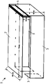
- the place where the cover 1 according to the invention is used is an airbag arrangement of a motor vehicle, with a motor vehicle interior lining or instrument panel, which has a passage opening for the impact cushion of an airbag.
- the airbag arrangement has a firing channel that accommodates the airbag cushion (cushion), the upper opening of which is closed by the cover 1, which has one or two airbag flaps 2 that span the upper opening of the firing channel. If only one airbag flap 2 is arranged, the external dimensions of the airbag flap correspond to the surface dimensions of the upper opening of the firing channel. If two airbag flaps are arranged, the external dimensions of an airbag flap correspond to half the area of the upper opening of the firing channel.
- the one or two airbag flap(s) 2 is/are fastened in an articulated manner with their longitudinal side via a hinge point 4 to a flap support wall 3 which surrounds the impact cushion through-opening of the firing channel.
- the flap support wall 3 surrounds the passage opening all around as a closed frame or the flap support wall 3 runs along the firing channel wall on the inside so far that at least the four corner regions of the firing channel close to the airbag flap(s) 2 are covered. In the latter case, one long side of the flap support wall 3 forms a gap.
- the articulation point 4 between the flap support wall 3 and the airbag flap(s) 2 is molded onto the airbag flap(s) and the flap support wall 3, so that the airbag flap(s), articulation point and flap support wall 3 are formed from a single plastic part that is produced using the plastic injection molding process .
- the articulation point 4 forms a fold (as is the case, for example, with the EP 2 727 775 A1 shows) as a material reservoir, so that the flap(s) can move outwards to a limited extent.
- the flap support wall 3 rests on the inside of the firing channel wall and is preferably attached to it.
- the airbag flap(s) 2, the flap support wall 3 and the hinge point 4 consist of a composite material with at least one layer of plastic strips and/or fibers, in particular thermoplastic polypropylene or polyester, and at least one plastic layer melted onto it.
- the plastic tapes or fibers can form a fabric.
- the lower edge of the flap support wall 3 forms regularly spaced tabs for attachment and the cover 1 is covered with an outer cover made of a plastic foam material and an outer skin.
Landscapes
- Engineering & Computer Science (AREA)
- Mechanical Engineering (AREA)
- Air Bags (AREA)
Description
- Die Erfindung betrifft eine Abdeckung über dem Schusskanal eines Airbags zum Verschluss einer Airbagdurchtrittsöffnung mit mindestens einer Airbagklappe, wobei die Abdeckung am Rand der Airbagklappe(n) mindestens eine Sollbruchlinie aufweist, um das Entfalten des Airbagkissens zu ermöglichen, und wobei die Airbagklappe(n) über eine Gelenkstelle mit einer Klappenstützwand angeformt verbunden ist/sind, die auf der Innenseite der Schusskanalwand insbesondere befestigt anliegt.
- Eine solche Abdeckung ist aus der
EP 2 727 775 A1 bekannt. Bei diesen Abdeckungen hat es sich gezeigt, dass der das Prallkissen aufnehmende Schusskanal nicht immer genügend widerstandsfähig ist. Dies besonders an den Stellen, an denen im Kunststoffspritzguss die Kunststofffronten aufeinandertreffen. - Abdeckungen für den Schusskanal eines Airbags sind auch aus der
WO 2005/090132 A1 und derDE 10 2012 109 350 A1 bekannt. Auch hier haben die vier Ecken des Schusskanals keine ausreichende Stabilität, so dass sich Teile beim Auslösen des Airbags lösen können. - Aufgabe der Erfindung ist es, eine Abdeckung der eingangs genannten Art so zu verbessern, dass der Schusskanal verstärkt ist ohne Gewichtserhöhung.
- Diese Aufgabe wird erfindungsgemäß dadurch gelöst, dass die Klappenstützwand entlang der Schusskanalwand innenseitig soweit umläuft, dass zumindest die der Airbagklappe(n) nahen vier Eckbereiche des Schusskanals bedeckt sind.
- Hierdurch bildet die Klappenstützwand eine Verstärkung des der Airbagklappe(n) nahen Bereichs des Schusskanals. Die Schusskanalwand und der Gelenkbereich der Airbagklappe(n) sind verstärkt, wobei auch die Stellen gesichert sind, an denen im Spritzguss die Kunststofffronten aufeinandertreffen.
- Vorzugsweise wird vorgeschlagen, dass die Klappenstützwand einen umlaufenden Rahmen bildet, an dessen Rahmenlängsseite(n) die Airbagklappe(n) über die Gelenkstelle verbunden ist/sind. Auch kann im Bereich der Gelenkstelle die Airbagklappe(n) und/oder die Klappenstützwand ein Materialreservoir in Form einer Faltung aufweisen, durch die die Airbagklappe(n) in ihrer Länge nach außen hin streckbar ist/sind. Ferner wird die Verstärkung dadurch erhöht, dass die Klappenstützwand an der Innenseite der Schusskanalwand befestigt ist.
- Eine große Austrittsöffnung für das Prallkissen ist gesichert, wenn die Flächengröße einer Airbagklappe oder zweier Airbagklappen der Fläche der Öffnung des Schusskanals entspricht.
- Eine besonders hohe Widerstandskraft wird erzielt, wenn die Airbagklappe(n) und die Klappenstützwand aus einem Verbundwerkstoff bestehen mit mindestens einer Lage aus Kunststoffbändern oder-fasern insbesondere aus thermoplastischem Polypropylen oder Polyester und mindestens einer darauf geschmolzenen Kunststofflage. Dabei können die Kunststoffbänder oder -fasern ein Gewebe bilden.
- Die Montage der Abdeckung wird erleichtert, wenn der untere Rand mindestens einer Rahmenlängsseite der Klappenstützwand Befestigungszungen aufweist. Ferner ist in der Regel die Abdeckung mit einer Außenabdeckung aus einem Kunststoffschaummaterial und einer Außenhaut bedeckt.
- Ein Ausführungsbeispiel der erfindungsgemäßen Abdeckung ist in der Zeichnung perspektivisch dargestellt und wird im Folgenden näher beschrieben.
- Der Ort, an dem die erfindungsgemäße Abdeckung 1 verwendet wird, ist eine Airbaganordnung eines Kraftfahrzeugs, mit einer Kfz.-Innenraumverkleidung oder Instrumententafel, die eine Durchtrittsöffnung für das Prallkissen eines Airbags aufweist. Die Airbaganordnung weist einen das Airbagkissen (Prallkissen) aufnehmenden Schusskanal auf, dessen obere Öffnung durch die Abdeckung 1 verschlossen ist, die eine oder zwei Airbagklappen 2 aufweist, die die obere Öffnung des Schusskanals überspannen. Bei Anordnung nur einer Airbagklappe 2 entsprechen die Außenabmessungen der Airbagklappe den Flächenabmessungen der oberen Öffnung des Schusskanals. Bei Anordnung von zwei Airbagklappen entsprechen die Außenabmessungen einer Airbagklappe der halben Fläche der oberen Öffnung des Schusskanals.
- Die eine oder zwei Airbagklappe(n) 2 ist/sind mit ihrer Längsseite über eine Gelenkstelle 4 an einer Klappenstützwand 3 gelenkig befestigt, die die Prallkissen-Durchtrittsöffnung des Schusskanals umgibt. Hierbei umgibt die Klappenstützwand 3 die Durchtrittsöffnung rundum als geschlossener Rahmen oder die Klappenstützwand 3 verläuft entlang der Schusskanalwand innenseitig soweit, dass zumindest die der Airbagklappe(n) 2 nahen vier Eckbereiche des Schusskanals bedeckt sind. Im letzten Fall bildet eine Längsseite der Klappenstützwand 3 eine Lücke.
- Die Gelenkstelle 4 zwischen Klappenstützwand 3 und Airbagklappe(n) 2 ist an der/den Airbagklappe(n) und der Klappenstützwand 3 angeformt, so dass Airbagklappe(n), Gelenkstelle und Klappenstützwand 3 von einem einzigen Kunststoffteil gebildet sind, das im Kunststoffspritzverfahren hergestellt ist. Hierbei bildet die Gelenkstelle 4 eine Faltung (wie dies beispielsweise die
EP 2 727 775 A1 zeigt) als Materialreservoir, so dass die Klappe(n) sich nach außen begrenzt bewegen können. - Die Klappenstützwand 3 liegt an der Innenseite der Schusskanalwand an und ist vorzugsweise an dieser befestigt.
- Die Airbagklappe(n) 2, die Klappenstützwand 3 und die Gelenkstelle 4 bestehen aus einem Verbundstoff mit mindestens einer Lage aus Kunststoffbändern und/oder -fasern insbesondere aus thermoplastischem Polypropylen oder Polyester und mindestens einer darauf geschmolzenen Kunststofflage. Hierbei können die Kunststoffbänder oder -fasern ein Gewebe bilden.
- Der untere Rand der Klappenstützwand 3 bildet zur Befestigung in regelmäßigen Abständen angeordnete Zungen und die Abdeckung 1 ist mit einer Außenabdeckung aus einem Kunststoffschaummaterial und einer Außenhaut bedeckt.
Claims (9)
- Abdeckung über dem Schusskanal eines Airbags zum Verschluss einer Airbagdurchtrittsöffnung mit mindestens einer Airbagklappe (2), wobei die Abdeckung (1) am Rand der Airbagklappe(n) (2) mindestens eine Sollbruchlinie aufweist, um das Entfalten des Airbagkissens zu ermöglichen, und wobei die Airbagklappe(n) (2) über eine Gelenkstelle (4) mit einer Klappenstützwand (3) angeformt verbunden ist/sind, die auf der Innenseite der Schusskanalwand insbesondere befestigt anliegt, dadurch gekennzeichnet, dass die Klappenstützwand (3) entlang der Schusskanalwand innenseitig soweit umläuft, dass zumindest die der Airbagklappe(n) (2) nahen vier Eckbereiche des Schusskanals bedeckt sind.
- Abdeckung (1) nach Anspruch 1, dadurch gekennzeichnet, dass die Klappenstützwand (3) einen umlaufenden Rahmen bildet, an dessen Rahmenlängsseite(n) die Airbagklappe(n) (2) über die Gelenkstelle (4) verbunden ist/sind.
- Abdeckung (1) nach Anspruch 1 oder 2, dadurch gekennzeichnet, dass im Bereich der Gelenkstelle (4) die Airbagklappe(n) (2) und/oder die Klappenstützwand (3) ein Materialreservoir in Form einer Faltung aufweist/aufweisen, durch die die Airbagklappe(n) (2) in ihrer Länge nach außen hin streckbar ist/sind.
- Abdeckung (1) nach einem der vorherigen Ansprüche, dadurch gekennzeichnet, dass die Klappenstützwand (3) an der Innenseite der Schusskanalwand befestigt ist.
- Abdeckung (1) nach einem der vorherigen Ansprüche, dadurch gekennzeichnet, dass die Flächengröße einer Airbagklappe (2) oder zweier Airbagklappen der Fläche der Öffnung des Schusskanals entspricht.
- Abdeckung (1) nach einem der vorherigen Ansprüche, dadurch gekennzeichnet, dass die Airbagklappe(n) (2) und die Klappenstützwand (3) aus einem Verbundwerkstoff bestehen mit mindestens einer Lage aus Kunststoffbändern oder -fasern insbesondere aus thermoplastischem Polypropylen oder Polyester und mindestens einer darauf geschmolzenen Kunststofflage.
- Abdeckung (1) nach Anspruch 6, dadurch gekennzeichnet, dass die Kunststoffbänder oder -fasern ein Gewebe bilden.
- Abdeckung (1) nach einem der vorherigen Ansprüche, dadurch gekennzeichnet, dass der untere Rand mindestens einer Rahmenlängsseite der Klappenstützwand (3) Befestigungszungen aufweist.
- Abdeckung (1) nach einem der vorherigen Ansprüche, dadurch gekennzeichnet, dass sie mit einer Außenabdeckung aus einem Kunststoffschaummaterial und einer Außenhaut bedeckt ist.
Applications Claiming Priority (2)
| Application Number | Priority Date | Filing Date | Title |
|---|---|---|---|
| DE102018006702.6A DE102018006702A1 (de) | 2018-08-24 | 2018-08-24 | Abdeckung eines Airbags |
| PCT/EP2019/000152 WO2020038595A1 (de) | 2018-08-24 | 2019-05-17 | Abdeckung eines airbags |
Publications (2)
| Publication Number | Publication Date |
|---|---|
| EP3684653A1 EP3684653A1 (de) | 2020-07-29 |
| EP3684653B1 true EP3684653B1 (de) | 2022-07-20 |
Family
ID=66752037
Family Applications (1)
| Application Number | Title | Priority Date | Filing Date |
|---|---|---|---|
| EP19728315.3A Active EP3684653B1 (de) | 2018-08-24 | 2019-05-17 | Abdeckung eines airbags |
Country Status (8)
| Country | Link |
|---|---|
| US (1) | US11524651B2 (de) |
| EP (1) | EP3684653B1 (de) |
| CN (1) | CN111295311B (de) |
| DE (1) | DE102018006702A1 (de) |
| ES (1) | ES2928764T3 (de) |
| MX (1) | MX2020004394A (de) |
| PT (1) | PT3684653T (de) |
| WO (1) | WO2020038595A1 (de) |
Families Citing this family (1)
| Publication number | Priority date | Publication date | Assignee | Title |
|---|---|---|---|---|
| US12257970B1 (en) | 2024-05-22 | 2025-03-25 | Faurecia Interior Systems, Inc. | Vehicle interior panel with folded hinge layer |
Citations (3)
| Publication number | Priority date | Publication date | Assignee | Title |
|---|---|---|---|---|
| US6089642A (en) * | 1998-03-09 | 2000-07-18 | Lear Automotive Dearborn, Inc. | Instrument panel seamless airbag cover |
| US20050140121A1 (en) * | 2003-12-24 | 2005-06-30 | Takata Corporation | Airbag device |
| EP2727775A1 (de) * | 2012-10-31 | 2014-05-07 | K.L. Kaschier- und Laminier GmbH | Airbag-Abdeckung mit mindestens einer Klappe |
Family Cites Families (15)
| Publication number | Priority date | Publication date | Assignee | Title |
|---|---|---|---|---|
| DE102004013036B4 (de) * | 2004-03-26 | 2011-04-14 | Faurecia Innenraum Systeme Gmbh | Vorrichtung zum Kopf- und/oder Schulteraufprallschutz bei einer Seitenkollision und/oder einem Überschlag |
| DE102010012136B4 (de) * | 2010-03-20 | 2015-12-31 | Volkswagen Ag | Vorrichtung, insbesondere Schusskanalmodul, zur Befestigung eines Airbagmoduls |
| FR2979600B1 (fr) * | 2011-09-01 | 2013-09-27 | Faurecia Interieur Ind | Dispositif de securite pour vehicule |
| KR101382329B1 (ko) * | 2012-09-19 | 2014-04-08 | 현대자동차 주식회사 | 자동차의 에어백 하우징 및 그 제조방법 |
| DE102012109350A1 (de) * | 2012-10-02 | 2014-08-14 | Autoliv Development Ab | Airbagmodul mit an einem verstärkten Randbereich des Containers befestigter Abdeckkappe |
| FR3007348B1 (fr) * | 2013-06-24 | 2017-12-22 | Faurecia Interieur Ind | Dispositif de securite pour vehicule |
| DE102013213791A1 (de) * | 2013-07-15 | 2015-01-15 | Volkswagen Aktiengesellschaft | Instrumententafel für ein Fahrzeug |
| US9421936B2 (en) * | 2013-11-29 | 2016-08-23 | Nihon Plast Co., Ltd. | Case member of airbag device, airbag device, method of manufacturing airbag device, and apparatus for manufacturing airbag device |
| US9352716B2 (en) * | 2014-03-14 | 2016-05-31 | Ford Global Technologies, Llc | Air bag door hinge for a motor vehicle |
| DE102017100330A1 (de) * | 2017-01-10 | 2018-07-12 | International Automotive Components Group Gmbh | Airbag-Anordnung und Verfahren zu ihrer Herstellung |
| US10220807B2 (en) * | 2017-03-22 | 2019-03-05 | Ford Global Technologies, Llc | Restricted-opening door hinge for automotive air bag chute |
| HUE056064T2 (hu) * | 2018-01-22 | 2022-01-28 | Motherson Innovations Co Ltd | Légzsákvezetõ berendezés egy gépjármû egy légzsákjának vezetésére, légzsák egység, ami tartalmaz egy ilyen légzsákvezetõ berendezést, valamint belsõ burkoló elem és eljárás egy ilyen belsõ burkoló elem elõállítására, ami tartalmaz egy ilyen légzsákvezet.. |
| DE102018006706A1 (de) * | 2018-08-24 | 2020-02-27 | K.L. Kaschier- Und Laminier Gmbh | Abdeckungsanordnung eines Airbags |
| DE102018006703A1 (de) * | 2018-08-24 | 2020-02-27 | K.L. Kaschier- Und Laminier Gmbh | Airbaganordnung |
| ES2927600T3 (es) * | 2019-04-24 | 2022-11-08 | Faurecia Interieur Ind | Sistema de airbag para un vehículo y método para fabricar el sistema de airbag |
-
2018
- 2018-08-24 DE DE102018006702.6A patent/DE102018006702A1/de not_active Withdrawn
-
2019
- 2019-05-17 ES ES19728315T patent/ES2928764T3/es active Active
- 2019-05-17 MX MX2020004394A patent/MX2020004394A/es unknown
- 2019-05-17 CN CN201980005425.2A patent/CN111295311B/zh active Active
- 2019-05-17 WO PCT/EP2019/000152 patent/WO2020038595A1/de not_active Ceased
- 2019-05-17 EP EP19728315.3A patent/EP3684653B1/de active Active
- 2019-05-17 US US16/642,808 patent/US11524651B2/en active Active
- 2019-05-17 PT PT197283153T patent/PT3684653T/pt unknown
Patent Citations (3)
| Publication number | Priority date | Publication date | Assignee | Title |
|---|---|---|---|---|
| US6089642A (en) * | 1998-03-09 | 2000-07-18 | Lear Automotive Dearborn, Inc. | Instrument panel seamless airbag cover |
| US20050140121A1 (en) * | 2003-12-24 | 2005-06-30 | Takata Corporation | Airbag device |
| EP2727775A1 (de) * | 2012-10-31 | 2014-05-07 | K.L. Kaschier- und Laminier GmbH | Airbag-Abdeckung mit mindestens einer Klappe |
Also Published As
| Publication number | Publication date |
|---|---|
| PT3684653T (pt) | 2022-10-20 |
| EP3684653A1 (de) | 2020-07-29 |
| US11524651B2 (en) | 2022-12-13 |
| WO2020038595A1 (de) | 2020-02-27 |
| CN111295311A (zh) | 2020-06-16 |
| DE102018006702A1 (de) | 2020-02-27 |
| MX2020004394A (es) | 2020-07-22 |
| CN111295311B (zh) | 2023-05-09 |
| ES2928764T3 (es) | 2022-11-22 |
| US20210170981A1 (en) | 2021-06-10 |
Similar Documents
| Publication | Publication Date | Title |
|---|---|---|
| EP2483111B1 (de) | Verkleidungsformteil zum abdecken eines airbags in einem kraftfahrzeug | |
| DE10345026B4 (de) | Innenverkleidungsteil zur Abdeckung eines Airbags | |
| DE102011122465B3 (de) | Aus Kunststoff bestehendes Abdeckelement für ein Fahrer-Gassackmodul und Abdeckung bestehend aus einem solchen Abdeckelement und einem auf diesem angeordneten Überzug | |
| EP3687866B1 (de) | Abdeckungsanordnung eines airbags | |
| DE212011100125U1 (de) | Aufblasbare Airbag-Anordnung mit einer Klappe, die über eine lineare Verbindung mit vier parallelen Halteabschnitten mit einem Armaturenbrett verbunden ist | |
| WO2008155020A1 (de) | Innenraumverkleidung mit integrierter airbagabdeckung für ein kraftfahrzeug sowie eine verfahren zu ihrer herstellung | |
| DE102015003638A1 (de) | Innenraumabdeckungen mit integrierten Airbagtüren für Kraftfahrzeuge sowie Verfahren zum Herstellen derselben | |
| DE4421820A1 (de) | Instrumententafel | |
| DE102006008564A1 (de) | Luftsackführung mit Abdeckung | |
| EP3684653B1 (de) | Abdeckung eines airbags | |
| EP2284048A1 (de) | Verkleidungsteil mit Airbagklappenanordnung im Innenraum eines Kraftfahrzeuges | |
| EP1291266B1 (de) | Hybridträger für ein Kraftfahrzeug | |
| EP1839953A2 (de) | Dichtungseinheit für ein Hohlprofil einer Fahrzeugkarosserie | |
| DE102012022899A1 (de) | Verbindungselement zur Abstützung eines Stoßfängers eines Kraftfahrzeuges gegenüber einem Montageträger, Baueinheit mit einem solchen Verbindungselement sowie Verfahren zur Herstellung eines Verbindungselements | |
| DE202014000565U1 (de) | Luftkanal zur Anordnung in der Fahrgastzelle eines Kraftfahrzeugs | |
| WO2018184910A1 (de) | Schiebedach windabweiserelement eines kraftfahrzeugs und windabweiser | |
| EP4151473B1 (de) | Textiles flächenelement eines airbags | |
| EP0303018A2 (de) | Klappverdeck für ein Cabriolet oder dergleichen Kfz | |
| DE102012005494A1 (de) | Fahrzeug | |
| DE10223898B4 (de) | Klappbare Haube für den Motor- oder Gepäckraum eines Kraftfahrzeugs | |
| DE102016001647A1 (de) | Verfahren zur Herstellung eines Verkleidungsteiles für ein Fahrzeug und Verkleidungsteil | |
| DE10231617B4 (de) | Innenverkleidungsteil für eine Seitentür | |
| DE112011104006T5 (de) | Verkleidungselement für Kraftfahrzeuge, umfassend einen Rahmen für die Entfaltung eines Airbags | |
| WO2019179698A1 (de) | Schusskanal für einen airbag eines kraftfahrzeugs | |
| DE10360326A1 (de) | Cabriolet-Fahrzeug mit einem beweglichen Dach oder bewegliches, für ein Cabriolet-Fahrzeug vorgesehenes Dach |
Legal Events
| Date | Code | Title | Description |
|---|---|---|---|
| STAA | Information on the status of an ep patent application or granted ep patent |
Free format text: STATUS: UNKNOWN |
|
| STAA | Information on the status of an ep patent application or granted ep patent |
Free format text: STATUS: THE INTERNATIONAL PUBLICATION HAS BEEN MADE |
|
| PUAI | Public reference made under article 153(3) epc to a published international application that has entered the european phase |
Free format text: ORIGINAL CODE: 0009012 |
|
| STAA | Information on the status of an ep patent application or granted ep patent |
Free format text: STATUS: REQUEST FOR EXAMINATION WAS MADE |
|
| 17P | Request for examination filed |
Effective date: 20200420 |
|
| AK | Designated contracting states |
Kind code of ref document: A1 Designated state(s): AL AT BE BG CH CY CZ DE DK EE ES FI FR GB GR HR HU IE IS IT LI LT LU LV MC MK MT NL NO PL PT RO RS SE SI SK SM TR |
|
| AX | Request for extension of the european patent |
Extension state: BA ME |
|
| STAA | Information on the status of an ep patent application or granted ep patent |
Free format text: STATUS: EXAMINATION IS IN PROGRESS |
|
| 17Q | First examination report despatched |
Effective date: 20210408 |
|
| DAV | Request for validation of the european patent (deleted) | ||
| DAX | Request for extension of the european patent (deleted) | ||
| GRAP | Despatch of communication of intention to grant a patent |
Free format text: ORIGINAL CODE: EPIDOSNIGR1 |
|
| STAA | Information on the status of an ep patent application or granted ep patent |
Free format text: STATUS: GRANT OF PATENT IS INTENDED |
|
| INTG | Intention to grant announced |
Effective date: 20220224 |
|
| GRAS | Grant fee paid |
Free format text: ORIGINAL CODE: EPIDOSNIGR3 |
|
| GRAA | (expected) grant |
Free format text: ORIGINAL CODE: 0009210 |
|
| STAA | Information on the status of an ep patent application or granted ep patent |
Free format text: STATUS: THE PATENT HAS BEEN GRANTED |
|
| AK | Designated contracting states |
Kind code of ref document: B1 Designated state(s): AL AT BE BG CH CY CZ DE DK EE ES FI FR GB GR HR HU IE IS IT LI LT LU LV MC MK MT NL NO PL PT RO RS SE SI SK SM TR |
|
| REG | Reference to a national code |
Ref country code: CH Ref legal event code: EP |
|
| REG | Reference to a national code |
Ref country code: DE Ref legal event code: R096 Ref document number: 502019005033 Country of ref document: DE |
|
| REG | Reference to a national code |
Ref country code: AT Ref legal event code: REF Ref document number: 1505348 Country of ref document: AT Kind code of ref document: T Effective date: 20220815 |
|
| REG | Reference to a national code |
Ref country code: IE Ref legal event code: FG4D Free format text: LANGUAGE OF EP DOCUMENT: GERMAN |
|
| REG | Reference to a national code |
Ref country code: PT Ref legal event code: SC4A Ref document number: 3684653 Country of ref document: PT Date of ref document: 20221020 Kind code of ref document: T Free format text: AVAILABILITY OF NATIONAL TRANSLATION Effective date: 20221014 |
|
| REG | Reference to a national code |
Ref country code: NL Ref legal event code: FP |
|
| REG | Reference to a national code |
Ref country code: LT Ref legal event code: MG9D |
|
| REG | Reference to a national code |
Ref country code: ES Ref legal event code: FG2A Ref document number: 2928764 Country of ref document: ES Kind code of ref document: T3 Effective date: 20221122 |
|
| REG | Reference to a national code |
Ref country code: SK Ref legal event code: T3 Ref document number: E 40618 Country of ref document: SK |
|
| PG25 | Lapsed in a contracting state [announced via postgrant information from national office to epo] |
Ref country code: SE Free format text: LAPSE BECAUSE OF FAILURE TO SUBMIT A TRANSLATION OF THE DESCRIPTION OR TO PAY THE FEE WITHIN THE PRESCRIBED TIME-LIMIT Effective date: 20220720 Ref country code: RS Free format text: LAPSE BECAUSE OF FAILURE TO SUBMIT A TRANSLATION OF THE DESCRIPTION OR TO PAY THE FEE WITHIN THE PRESCRIBED TIME-LIMIT Effective date: 20220720 Ref country code: NO Free format text: LAPSE BECAUSE OF FAILURE TO SUBMIT A TRANSLATION OF THE DESCRIPTION OR TO PAY THE FEE WITHIN THE PRESCRIBED TIME-LIMIT Effective date: 20221020 Ref country code: LV Free format text: LAPSE BECAUSE OF FAILURE TO SUBMIT A TRANSLATION OF THE DESCRIPTION OR TO PAY THE FEE WITHIN THE PRESCRIBED TIME-LIMIT Effective date: 20220720 Ref country code: LT Free format text: LAPSE BECAUSE OF FAILURE TO SUBMIT A TRANSLATION OF THE DESCRIPTION OR TO PAY THE FEE WITHIN THE PRESCRIBED TIME-LIMIT Effective date: 20220720 Ref country code: FI Free format text: LAPSE BECAUSE OF FAILURE TO SUBMIT A TRANSLATION OF THE DESCRIPTION OR TO PAY THE FEE WITHIN THE PRESCRIBED TIME-LIMIT Effective date: 20220720 |
|
| PG25 | Lapsed in a contracting state [announced via postgrant information from national office to epo] |
Ref country code: PL Free format text: LAPSE BECAUSE OF FAILURE TO SUBMIT A TRANSLATION OF THE DESCRIPTION OR TO PAY THE FEE WITHIN THE PRESCRIBED TIME-LIMIT Effective date: 20220720 Ref country code: IS Free format text: LAPSE BECAUSE OF FAILURE TO SUBMIT A TRANSLATION OF THE DESCRIPTION OR TO PAY THE FEE WITHIN THE PRESCRIBED TIME-LIMIT Effective date: 20221120 Ref country code: HR Free format text: LAPSE BECAUSE OF FAILURE TO SUBMIT A TRANSLATION OF THE DESCRIPTION OR TO PAY THE FEE WITHIN THE PRESCRIBED TIME-LIMIT Effective date: 20220720 Ref country code: GR Free format text: LAPSE BECAUSE OF FAILURE TO SUBMIT A TRANSLATION OF THE DESCRIPTION OR TO PAY THE FEE WITHIN THE PRESCRIBED TIME-LIMIT Effective date: 20221021 |
|
| REG | Reference to a national code |
Ref country code: DE Ref legal event code: R097 Ref document number: 502019005033 Country of ref document: DE |
|
| PG25 | Lapsed in a contracting state [announced via postgrant information from national office to epo] |
Ref country code: SM Free format text: LAPSE BECAUSE OF FAILURE TO SUBMIT A TRANSLATION OF THE DESCRIPTION OR TO PAY THE FEE WITHIN THE PRESCRIBED TIME-LIMIT Effective date: 20220720 Ref country code: RO Free format text: LAPSE BECAUSE OF FAILURE TO SUBMIT A TRANSLATION OF THE DESCRIPTION OR TO PAY THE FEE WITHIN THE PRESCRIBED TIME-LIMIT Effective date: 20220720 Ref country code: DK Free format text: LAPSE BECAUSE OF FAILURE TO SUBMIT A TRANSLATION OF THE DESCRIPTION OR TO PAY THE FEE WITHIN THE PRESCRIBED TIME-LIMIT Effective date: 20220720 Ref country code: CZ Free format text: LAPSE BECAUSE OF FAILURE TO SUBMIT A TRANSLATION OF THE DESCRIPTION OR TO PAY THE FEE WITHIN THE PRESCRIBED TIME-LIMIT Effective date: 20220720 |
|
| PLBE | No opposition filed within time limit |
Free format text: ORIGINAL CODE: 0009261 |
|
| STAA | Information on the status of an ep patent application or granted ep patent |
Free format text: STATUS: NO OPPOSITION FILED WITHIN TIME LIMIT |
|
| PG25 | Lapsed in a contracting state [announced via postgrant information from national office to epo] |
Ref country code: EE Free format text: LAPSE BECAUSE OF FAILURE TO SUBMIT A TRANSLATION OF THE DESCRIPTION OR TO PAY THE FEE WITHIN THE PRESCRIBED TIME-LIMIT Effective date: 20220720 |
|
| 26N | No opposition filed |
Effective date: 20230421 |
|
| PG25 | Lapsed in a contracting state [announced via postgrant information from national office to epo] |
Ref country code: AL Free format text: LAPSE BECAUSE OF FAILURE TO SUBMIT A TRANSLATION OF THE DESCRIPTION OR TO PAY THE FEE WITHIN THE PRESCRIBED TIME-LIMIT Effective date: 20220720 |
|
| PG25 | Lapsed in a contracting state [announced via postgrant information from national office to epo] |
Ref country code: SI Free format text: LAPSE BECAUSE OF FAILURE TO SUBMIT A TRANSLATION OF THE DESCRIPTION OR TO PAY THE FEE WITHIN THE PRESCRIBED TIME-LIMIT Effective date: 20220720 |
|
| REG | Reference to a national code |
Ref country code: CH Ref legal event code: PL |
|
| PG25 | Lapsed in a contracting state [announced via postgrant information from national office to epo] |
Ref country code: MC Free format text: LAPSE BECAUSE OF FAILURE TO SUBMIT A TRANSLATION OF THE DESCRIPTION OR TO PAY THE FEE WITHIN THE PRESCRIBED TIME-LIMIT Effective date: 20220720 |
|
| GBPC | Gb: european patent ceased through non-payment of renewal fee |
Effective date: 20230517 |
|
| PG25 | Lapsed in a contracting state [announced via postgrant information from national office to epo] |
Ref country code: MC Free format text: LAPSE BECAUSE OF FAILURE TO SUBMIT A TRANSLATION OF THE DESCRIPTION OR TO PAY THE FEE WITHIN THE PRESCRIBED TIME-LIMIT Effective date: 20220720 Ref country code: LU Free format text: LAPSE BECAUSE OF NON-PAYMENT OF DUE FEES Effective date: 20230517 Ref country code: LI Free format text: LAPSE BECAUSE OF NON-PAYMENT OF DUE FEES Effective date: 20230531 Ref country code: CH Free format text: LAPSE BECAUSE OF NON-PAYMENT OF DUE FEES Effective date: 20230531 |
|
| REG | Reference to a national code |
Ref country code: IE Ref legal event code: MM4A |
|
| PG25 | Lapsed in a contracting state [announced via postgrant information from national office to epo] |
Ref country code: IE Free format text: LAPSE BECAUSE OF NON-PAYMENT OF DUE FEES Effective date: 20230517 |
|
| PG25 | Lapsed in a contracting state [announced via postgrant information from national office to epo] |
Ref country code: IE Free format text: LAPSE BECAUSE OF NON-PAYMENT OF DUE FEES Effective date: 20230517 Ref country code: GB Free format text: LAPSE BECAUSE OF NON-PAYMENT OF DUE FEES Effective date: 20230517 |
|
| PG25 | Lapsed in a contracting state [announced via postgrant information from national office to epo] |
Ref country code: BG Free format text: LAPSE BECAUSE OF FAILURE TO SUBMIT A TRANSLATION OF THE DESCRIPTION OR TO PAY THE FEE WITHIN THE PRESCRIBED TIME-LIMIT Effective date: 20220720 |
|
| PG25 | Lapsed in a contracting state [announced via postgrant information from national office to epo] |
Ref country code: BG Free format text: LAPSE BECAUSE OF FAILURE TO SUBMIT A TRANSLATION OF THE DESCRIPTION OR TO PAY THE FEE WITHIN THE PRESCRIBED TIME-LIMIT Effective date: 20220720 |
|
| PGFP | Annual fee paid to national office [announced via postgrant information from national office to epo] |
Ref country code: NL Payment date: 20250522 Year of fee payment: 7 |
|
| PGFP | Annual fee paid to national office [announced via postgrant information from national office to epo] |
Ref country code: DE Payment date: 20250519 Year of fee payment: 7 |
|
| PGFP | Annual fee paid to national office [announced via postgrant information from national office to epo] |
Ref country code: ES Payment date: 20250616 Year of fee payment: 7 |
|
| PGFP | Annual fee paid to national office [announced via postgrant information from national office to epo] |
Ref country code: IT Payment date: 20250530 Year of fee payment: 7 Ref country code: BE Payment date: 20250520 Year of fee payment: 7 |
|
| REG | Reference to a national code |
Ref country code: AT Ref legal event code: MM01 Ref document number: 1505348 Country of ref document: AT Kind code of ref document: T Effective date: 20240517 |
|
| PGFP | Annual fee paid to national office [announced via postgrant information from national office to epo] |
Ref country code: PT Payment date: 20250507 Year of fee payment: 7 |
|
| PGFP | Annual fee paid to national office [announced via postgrant information from national office to epo] |
Ref country code: FR Payment date: 20250526 Year of fee payment: 7 |
|
| PG25 | Lapsed in a contracting state [announced via postgrant information from national office to epo] |
Ref country code: AT Free format text: LAPSE BECAUSE OF NON-PAYMENT OF DUE FEES Effective date: 20240517 |
|
| PG25 | Lapsed in a contracting state [announced via postgrant information from national office to epo] |
Ref country code: CY Free format text: LAPSE BECAUSE OF FAILURE TO SUBMIT A TRANSLATION OF THE DESCRIPTION OR TO PAY THE FEE WITHIN THE PRESCRIBED TIME-LIMIT; INVALID AB INITIO Effective date: 20190517 |
|
| PGFP | Annual fee paid to national office [announced via postgrant information from national office to epo] |
Ref country code: TR Payment date: 20250508 Year of fee payment: 7 Ref country code: SK Payment date: 20250506 Year of fee payment: 7 |
|
| PG25 | Lapsed in a contracting state [announced via postgrant information from national office to epo] |
Ref country code: HU Free format text: LAPSE BECAUSE OF FAILURE TO SUBMIT A TRANSLATION OF THE DESCRIPTION OR TO PAY THE FEE WITHIN THE PRESCRIBED TIME-LIMIT; INVALID AB INITIO Effective date: 20190517 |
|
| PGFP | Annual fee paid to national office [announced via postgrant information from national office to epo] |
Ref country code: AT Payment date: 20260410 Year of fee payment: 5 |