EP3684704B1 - Joint d'étanchéité de bec verseur destiné à un contenant - Google Patents
Joint d'étanchéité de bec verseur destiné à un contenant Download PDFInfo
- Publication number
- EP3684704B1 EP3684704B1 EP18859017.8A EP18859017A EP3684704B1 EP 3684704 B1 EP3684704 B1 EP 3684704B1 EP 18859017 A EP18859017 A EP 18859017A EP 3684704 B1 EP3684704 B1 EP 3684704B1
- Authority
- EP
- European Patent Office
- Prior art keywords
- seal
- spout
- container
- annular
- annular end
- Prior art date
- Legal status (The legal status is an assumption and is not a legal conclusion. Google has not performed a legal analysis and makes no representation as to the accuracy of the status listed.)
- Active
Links
Images





Classifications
-
- B—PERFORMING OPERATIONS; TRANSPORTING
- B65—CONVEYING; PACKING; STORING; HANDLING THIN OR FILAMENTARY MATERIAL
- B65D—CONTAINERS FOR STORAGE OR TRANSPORT OF ARTICLES OR MATERIALS, e.g. BAGS, BARRELS, BOTTLES, BOXES, CANS, CARTONS, CRATES, DRUMS, JARS, TANKS, HOPPERS, FORWARDING CONTAINERS; ACCESSORIES, CLOSURES, OR FITTINGS THEREFOR; PACKAGING ELEMENTS; PACKAGES
- B65D47/00—Closures with filling and discharging, or with discharging, devices
- B65D47/04—Closures with discharging devices other than pumps
- B65D47/06—Closures with discharging devices other than pumps with pouring spouts or tubes; with discharge nozzles or passages
- B65D47/061—Closures with discharging devices other than pumps with pouring spouts or tubes; with discharge nozzles or passages with telescopic, retractable or reversible spouts, tubes or nozzles
- B65D47/063—Closures with discharging devices other than pumps with pouring spouts or tubes; with discharge nozzles or passages with telescopic, retractable or reversible spouts, tubes or nozzles with flexible parts
-
- B—PERFORMING OPERATIONS; TRANSPORTING
- B65—CONVEYING; PACKING; STORING; HANDLING THIN OR FILAMENTARY MATERIAL
- B65D—CONTAINERS FOR STORAGE OR TRANSPORT OF ARTICLES OR MATERIALS, e.g. BAGS, BARRELS, BOTTLES, BOXES, CANS, CARTONS, CRATES, DRUMS, JARS, TANKS, HOPPERS, FORWARDING CONTAINERS; ACCESSORIES, CLOSURES, OR FITTINGS THEREFOR; PACKAGING ELEMENTS; PACKAGES
- B65D47/00—Closures with filling and discharging, or with discharging, devices
- B65D47/04—Closures with discharging devices other than pumps
- B65D47/20—Closures with discharging devices other than pumps comprising hand-operated members for controlling discharge
- B65D47/26—Closures with discharging devices other than pumps comprising hand-operated members for controlling discharge with slide valves, i.e. valves that open and close a passageway by sliding over a port, e.g. formed with slidable spouts
- B65D47/28—Closures with discharging devices other than pumps comprising hand-operated members for controlling discharge with slide valves, i.e. valves that open and close a passageway by sliding over a port, e.g. formed with slidable spouts having linear movement
-
- B—PERFORMING OPERATIONS; TRANSPORTING
- B65—CONVEYING; PACKING; STORING; HANDLING THIN OR FILAMENTARY MATERIAL
- B65D—CONTAINERS FOR STORAGE OR TRANSPORT OF ARTICLES OR MATERIALS, e.g. BAGS, BARRELS, BOTTLES, BOXES, CANS, CARTONS, CRATES, DRUMS, JARS, TANKS, HOPPERS, FORWARDING CONTAINERS; ACCESSORIES, CLOSURES, OR FITTINGS THEREFOR; PACKAGING ELEMENTS; PACKAGES
- B65D47/00—Closures with filling and discharging, or with discharging, devices
- B65D47/04—Closures with discharging devices other than pumps
- B65D47/20—Closures with discharging devices other than pumps comprising hand-operated members for controlling discharge
- B65D47/26—Closures with discharging devices other than pumps comprising hand-operated members for controlling discharge with slide valves, i.e. valves that open and close a passageway by sliding over a port, e.g. formed with slidable spouts
- B65D47/28—Closures with discharging devices other than pumps comprising hand-operated members for controlling discharge with slide valves, i.e. valves that open and close a passageway by sliding over a port, e.g. formed with slidable spouts having linear movement
- B65D47/283—Closures with discharging devices other than pumps comprising hand-operated members for controlling discharge with slide valves, i.e. valves that open and close a passageway by sliding over a port, e.g. formed with slidable spouts having linear movement between tubular parts
Definitions
- the present disclosure relates to a container including a retractable spout, and a seal for the retractable spout of the container, and to a method of sealing a container with a movable spout.
- dispensing containers there are various types of dispensing containers currently on the market that include a sealable spout.
- a popular use of such dispensing containers is for drink bottles configured to hold water or other fluids.
- a simply type of spout used for drinking bottles has a push-pull configuration, wherein when the spout is physically pulled into an extended arrangement a passageway is opened to allow movement of the fluid therethrough.
- a push-pull configuration wherein when the spout is physically pulled into an extended arrangement a passageway is opened to allow movement of the fluid therethrough.
- spout is disclosed in US Patent 8701906 to Blast Max LLC. , that has a push-pull, flow-through drinking spout including upper and lower seals.
- WO 2016/044890 discloses a container according to the preamble of claim 1.
- bite-actuated mouthpieces however have a tendency to suffer from mechanical damage during use, which may lead to leakage or failure of the seal.
- a container including a retractable spout, and a seal for the retractable spout of the container, as claimed in claim 1.
- the intermediate portion of the tubular body is configured to move inwardly of the first annular end, such that the intermediate portion is inverted or folded over itself as the spout is moved from said retracted position into the extended position. In a sense the tubular body rolls or folds over itself as the spout moves into the retracted position.
- the intermediate portion may be of a uniform thickness or may have a plurality of annular grooves or ridges therearound.
- the first annular end is fixedly held by the internal frame, wherein the spout is able to at least partly retract through the second aperture when in said retracted position, and extend at least partly through the first aperture when in said extended position.
- the second aperture of the internal frame is dimensioned to allow passage of at least a part of the intermediate portion therethrough and may be dimensioned to allow passage of the second annular end, when the spout is being moved between the retracted and extended positions.
- the internal frame may include a plurality of depending legs, preferably three legs, which hold the platform in a spaced apart position inwardly of said opening.
- depending legs and platform are unitary in construction.
- the first end of the seal includes an outwardly projecting circumferential shoulder, wherein a downwardly open groove extends into or is formed by the shoulder, such that the groove extends generally circumferentially around the first end.
- the upper surface of the shoulder may also include an inner annular lip that extends therearound. The shoulder is configured to engage with the internal frame to thereby fixedly hold the first end thereto.
- the internal frame is formed by two separate members that are configured to cooperate to thereby hold or clamp the first end or shoulder of the seal therebetween.
- the internal frame may comprise an upper surface of a base member and an insert that may be connected to the lid base member using fixing means such as screws or may be configured to clip together or frictionally engage.
- the upper surface of the lid base member may include an annular shaped upstand that is configured to engage with the downwardly open groove of the seal, and the insert abuts an upper surface of the shoulder outwardly of the inner annular lip.
- the inner annular lip provides greater flexibility for the intermediate portion as it moves inwardly of the first annular end.
- the intermediate portion of the seal may be tapered inwardly toward the second annular end, at between 1 and 5 degrees, and preferably 2 degrees, wherein the tapered intermediate portion is configured to engage with a correspondingly shaped tapered portion of the spout to thereby assist with maintaining frictional engagement therebetween.
- the seal profile will be easier where the seal includes a taper.
- the spout preferably has a corresponding taper so that the seal remains supported at least partially therealong.
- the taper is not essential and furthermore a tapered seal could be used on a spout that does not include a corresponding taper.
- the seal may be constructed from thermoplastic elastomers (TPE) having a polypropylene base.
- TPE thermoplastic elastomers
- Other copolymers or polymer mixes with thermoplastic and elastomeric properties may also be used.
- Other materials that could be used include, but are not limited to, silicon rubber, EPDM rubber, silicon or any material with suitable elastomeric properties.
- UV stabilisers may be added to the material forming the seal to inhibit degradation due to the effects of sunlight.
- the seal is unitary in construction and may be formed by injection moulding.
- seal 10 for a spout 12 of a container 14 demonstrating by way of examples, arrangements in which the principles of the present invention may be employed.
- the seal 10 includes a first annular end 16 that is configured to be fixedly held circumferentially adjacent an opening 18 in the container 14.
- the seal 10 further includes a second annular end 20 for engagement with and configured to extend downwardly from an inner or lower end 22 of said spout 12, as illustrated in Figure 3a .
- An intermediate portion 24 of the seal 10 is tubular.
- the first annular end 16 includes an outwardly projecting circumferential shoulder 26, as illustrated in Figure 2 .
- the circumferential shoulder 26 includes a downwardly open groove 28 that extends thereinto or is at least formed by the shoulder 26, such that the groove 28 extends generally circumferentially around the first annular end 16.
- the upper surface of the shoulder 26 includes an annular lip 30 that extends therearound.
- the second annular end 20 includes two spaced apart thickened portions 32, 34, which assist in the engagement with the lower end 22 of the spout 12 and inhibits the seal 10 from detaching therefrom.
- the thickened portions 32, 34 also assist with sealing when abutting the platform 56.
- the second annular end 20 may not include thickened portions, such that it is of uniform thickness, whereby in such a case engagement would rely primarily upon frictional engagement to inhibit detachment from the spout 12.
- FIGS 3a and 3b illustrate the attachment of the seal 10 to one embodiment of the container 14 having a movable spout 12.
- the container 14 includes a base 36 defining a chamber 38 for holding a flowable material 40, in the present embodiment being a liquid.
- a lid assembly 42 is attached to the base 36 by way of cooperating screw threads 44, 46.
- the lid assembly 42 includes an internal frame 48 having aperture 50 and a top cover 52 also including an aperture 54.
- the apertures 50 and 54 coaxially align to thereby define the opening 18 in the container 14.
- the internal frame 48 further include a depending leg or legs 56 that are configured to hold the platform 56 spaced apart from the opening 18.
- first annular end 16 is attached to or fixedly held by the internal frame 48.
- the second annular end 20 is configured to engage with and extend downwardly from the inner end 22 of said spout 12.
- the spout 12 is able to, at least partly, retract through aperture 50 when in the retracted position, whereby the second annular end 20 bears against the platform 58 to thereby inhibit movement of the liquid out through the spout 12.
- the first and second annular ends 16, 20 remain fixed to frame 48 or spout 12 respectively.
- the spout 12 extends at least partly out through aperture 54 in the top cover 52 when in the extended position and the fluid 38 is able to move out through the opening 18, as indicated by the broken arrow in Figure 3b , when the container 14 is tilted.
- the flow of fluid 38 is inhibited or stopped because the second annular end 20 bears against the bearing surface of the platform 58.
- Figure 4 illustrates an exploded view of one possible embodiment of the lid assembly 42. Similar configurations of movable spouts have been previously disclosed by the present Applicant in International Applications, PCT/AU2015/050567 entitled Bottle Lid Assembly with Retractable Spout, and PCT/AU2018/050293 entitled Apparatus and Method for Measuring Fluid Consumption. Some of the details of the movable spout and operation thereof, will not be repeated to not obscure the present invention.
- the top cover 52 of the present embodiment can be fixed relative to a lid base member 60 by way of fixing members 62.
- the top cover 52 includes the aperture 54 that can be closed by a pivotable flap 64.
- the spout 12 includes a fluid pathway 66, mouthpiece 68, inner end 22 and projection 70 having fingers 72a, 72b, 72c that extend sidewardly from an opposite side of the spout 12.
- the projection 70 includes apertures 74 that are configured to engage respective spring posts 76.
- the lid assembly 42 further includes a generally cylindrical main body 78, that is able to rotated relative to the lid base member 60 and includes inwardly projecting flanges 80a, 80b, 80c in the form of a flight or three start threads.
- the fingers 72a, 72b, 72c abut an underside of the inwardly projecting flanges 80a, 80b, 80c and act as a guide when the spout 16 is moving between retracted and extended positions, as disclosed in PCT/AU2015/050567 .
- the lid base member 60 includes three depending legs 56a, 56b and 56c that support or hold the platform 58 spaced apart from the opening 18.
- the lid assembly 42 further includes a latch mechanism 82 that inhibits rotation of the main body 78 against the influence of biasing springs (not shown) that engage respective spring posts 76.
- the lid assembly 42 also includes an insert 84 having apertures 86, 90 shaped to slid over spring posts 76 and permit passage of the spout 12 therethrough.
- the insert 84 is attached to the lid base member 60 by way of screws (not shown) that engage though respective apertures.
- Three legs 92 extend upwardly and are configured to engage a plate 94 that is attached over spring posts 76 that passes though apertures 96.
- the plate 94 similarly includes an aperture 98 that permits passage of the spout 12 therethrough.
- Figures 5a to 5c illustrate the operation of the lid assembly 42 of the present embodiment.
- Figure 5a illustrates the spout 12 in a retracted position within the lid assembly 42, wherein the pivotable flap 64 covers or closes aperture 54.
- the releasable latch mechanism 82 comprises a button 100 and locking device 102, wherein rotation of the main body 78 is inhibited.
- a user releases the locking device 102 and depresses the button 100 to trigger the spout 16 to move under the influence of the biasing springs from the retracted position, as shown in Figure 5a , into the extended position, as shown in Figure 5c .
- This is accomplished by rotation of the main body 78 around the longitudinal axis 88, as indicated by the arrow in Figure 5b .
- the pivotable flap 64 clears the aperture 54 to enable the spout 12 to move upwardly therethrough, from the retracted position to the extended position.
- the user can utilise the spout 16 to access the fluid 40 contained within the bottle 14.
- the user When the user has finished drinking or pouring fluid from the spout 12, they can grasp the outer surface of the main body 78 and manually rotate it against the bias of the biasing springs into the closed position, wherein the spout 12 is retracted and the pivotable flap 64 closes opening 54.
- the latch mechanism 82 then maintains the spout 12 in the retracted position against the bias until the button 100 is actuated by a user.
- the base member 60 includes an upstand 104 that has an annular shape and is configured to engage with the downwardly open groove 28 of the seal 10.
- the insert 84 abuts an upper surface of the shoulder 26 outwardly of the lip 30.
- the inner or lower end 22 of the spout 12 includes a slit 106 extending circumferentially around the spout 22 that is configured to engage with thickened portion 32 of the seal 10, as shown in Figures 6 , 9 and 12 .
- the slit 106 is configured to assist in maintaining the position of the second annular end 20 on the inner end 22 of the spout 12. The reader should however appreciate that according to claim 1, the inner end 22 frictionally engages the second annular end 20.
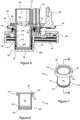
- Figures 6 to 8 illustrate the arrangement of the seal 10 when the spout 12 is in a retracted positioned.
- the intermediate portion 24 is stretch downwardly over the outer surface of the spout 12 and the second end 20 is compressed against the platform 58. It should be appreciated by the reader that the intermediate portion 24 preferably conforms to the outer surface of the spout 12.
- FIGs 9 to 11 illustrate the arrangement of the seal 10 and spout 12 in an intermediate position 24 between the fully retracted and fully extended positions. As the spout 12 moves upwardly the intermediate portion 24 begins to invert or fold over itself as it moves inwardly through the first annular end 16. The reader should appreciate that the inner annular lip 30 provides greater flexibility for the intermediate portion 24 as it moves inwardly through the first annular end 16.
- the second annular end 20 is also now in an uncompressed arrangement, as can best be seen by comparing Figures 6 and 9 or Figures 8 and 11 .
- Figures 12 to 14 illustrate the arrangement of the seal 10 and spout 12 in a fully extended position.
- the second annular end 20 remains inwardly of the first annular end 16 with the intermediate position 24 completely folded over itself and extending upwardly through the aperture 86 of the insert 84.
- Figures 15 to 17 illustrate a simplified configuration of the lid assembly 42 and the progressive movement of the spout 12 from a retracted position, as illustrated in Figure 15 , through an intermediate position, as illustrated in Figure 16 , into an extended position, as illustrated in Figure 17 .
- the reader will appreciate that Figures 15 to 17 illustrate the movement of seal 10 at is inverts or folds over itself.
- Figure 18 illustrates a second embodiment of the seal 10 that has a tapered intermediate portion 24, such that it is configured to engage with a tapered portion 108 of the spout 12.
- the taper on the seal 10 of the present embodiment is 2 degrees and the tapered portion 108 of the spout 12 is correspondingly shaped to assist with maintaining fractional engagement.
- the second annular end 20 of the seal 10 in the present embodiment is of uniform thickness and does not include thickened portions. Therefore, the inner end 22 of the spout 12, shown in Figure 18 , does not include a slit 106 extending circumferentially around the spout 22, however the reader should appreciate that the end 22 may alternatively include an annular slit, as previously discussed, for retaining a part of the seal 10.
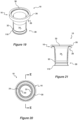
- Figures 19 to 21 show another embodiment of the seal 10 that includes a lower or second annular end 20 having a thickened portion 32 and a depending annular skirt 110, which bears against the platform 58 when the spout 12 is in the retracted position. As illustrated in Figure 21 , the skirt 110 is splayed towards a lower edge to assist in sealing against the platform 58.
- the thickened portion 32 is configured to engage overhang 112, illustrated in Figure 22 , that is located at the lower end 22 of said spout 12.
- Figure 22 further illustrates rollers 114a, 114b, 114c, that engage respective spigots 116 on fingers 72a, 72b, 72c.
- the rollers 114a, 114b, 114c engage an underside of the inwardly projecting flanges 80a, 80b, 80c to reduce friction and thereby assist in the movement of the spout 12 between retracted and extended positions, as described in PCT/AU2015/050567 .
- the present embodiment discloses a sealable container and method of use.
- Various fixing means and other components may be used to construct the lid assembly 14, which are not currently illustrated but which would be obvious to a person skilled in the art. Details of some of the fixing means other components or equivalent parts, and the operation of the moveable spout in general are detailed in International Applications PCT/AU2015/050567 and PCT/AU2018/050293 , both in the name of the present Application.
- a seal for a drinking vessel and a sealable container including a seal.
- the seal inhibits movement of the liquid or other flowable material out between the outer surface of the spout and the sides of the opening through which the spout is configured to extend. Furthermore, the seal inhibits movement of the flowable material out through the spout when in a retracted position.
- the invention provides a dual function seal for a movable spout.
Landscapes
- Engineering & Computer Science (AREA)
- Mechanical Engineering (AREA)
- Closures For Containers (AREA)
- Tubes (AREA)
Claims (14)
- Contenant (14) incluant un bec verseur rétractable (12), et un joint d'étanchéité (10) pour le bec verseur rétractable (12) du contenant (14), le contenant (14) incluant un ensemble de couvercle (42) comportant un capuchon (52) doté d'un premier orifice (54) s'étendant à travers celui-ci et une ossature interne (48) comportant un deuxième orifice (50) s'étendant à travers celle-ci, les premier et deuxième orifices (54, 50) s'alignant coaxialement pour délimiter ainsi une ouverture (18) dans le contenant (14), et une surface de butée comprenant un socle (58) qui est espacé de ladite ouverture (18), caractérisé en ce que le joint d'étanchéité (10) comprend :un corps tubulaire flexible généralement allongé ; etune première extrémité annulaire (16) étant connectée fixement à ladite ossature interne (48) de manière adjacente à l'ouverture (18) dans ledit contenant (14) à travers laquelle ledit bec verseur rétractable (12) est configuré pour se déplacer, pour ainsi empêcher un mouvement d'une substance fluide hors d'une surface extérieure du dit corps tubulaire et d'un bord de ladite ouverture (18) ;dans lequel une partie intermédiaire (24) du corps tubulaire est configurée pour se déplacer vers l'intérieur de la première extrémité annulaire (16), de telle sorte que la partie intermédiaire (24) est retournée ou pliée sur elle-même lorsque le bec verseur (12) est déplacé d'une position rétractée jusqu'à une position étendue ;dans lequel le joint d'étanchéité (10) comprend :
une deuxième extrémité annulaire opposée (20) qui vient en prise par friction avec et s'étend vers le bas à partir d'une extrémité inférieure du dit bec verseur rétractable (12), au moyen de quoi, lorsque le bec verseur rétractable (12) est dans la position rétractée, la deuxième extrémité annulaire (20) du joint d'étanchéité (10) repose contre ladite surface de butée du contenant (14) pour empêcher ainsi un mouvement de ladite substance fluide vers l'extérieur à travers ledit bec verseur rétractable (12). - Contenant (14) et joint d'étanchéité (10) selon la revendication 1, dans lequel la deuxième extrémité annulaire (20) du joint d'étanchéité (10) inclut au moins une partie annulaire épaissie (32, 34) configurée pour faciliter la mise en prise par friction de l'extrémité inférieure du bec verseur rétractable (12) pour empêcher ainsi la deuxième extrémité annulaire (20) de se séparer de celle-ci.
- Contenant (14) et joint d'étanchéité (10) selon la revendication 1, dans lequel la deuxième extrémité annulaire (20) du joint d'étanchéité (10) inclut une pluralité de parties annulaires épaissies espacées (32, 34), dans lequel les parties annulaires épaissies (32, 34) facilitent la mise en prise par friction de l'extrémité inférieure du bec verseur (12) pour empêcher ainsi la deuxième extrémité annulaire (20) de se séparer de celle-ci.
- Contenant (14) et joint d'étanchéité (10) selon la revendication 2 ou 3, dans lequel l'extrémité inférieure du bec verseur rétractable (12) inclut une fente (106) s'étendant périphériquement autour du bec verseur rétractable (12) et étant configurée pour venir en prise avec une (32, 34) ou des parties annulaires épaissies respectives (32, 34) du joint d'étanchéité (10).
- Contenant (14) et joint d'étanchéité (10) selon la revendication 1, dans lequel la première extrémité annulaire (16) est maintenue fixement par l'ossature interne (48), dans lequel le bec verseur (12) est apte à se rétracter au moins en partie à travers le deuxième orifice (50) lorsqu'il est dans ladite position rétractée, et à s'étendre au moins en partie à travers le premier orifice (54) lorsqu'il est dans ladite position étendue.
- Contenant (14) et joint d'étanchéité (10) selon la revendication 5, dans lequel le deuxième orifice (50) de l'ossature interne (48) est dimensionné pour permettre le passage d'au moins une partie de la partie intermédiaire (24) du joint d'étanchéité (10) à travers celui-ci et est dimensionné pour permettre le passage de la deuxième extrémité annulaire (20), lorsque le bec verseur (12) est déplacé entre la position rétractée et la position étendue.
- Contenant (14) et joint d'étanchéité (10) selon la revendication 6, dans lequel l'ossature interne (48) inclut une pluralité de pieds suspendus (56), qui maintiennent le socle (48) dans une position espacée vers l'intérieur de ladite ouverture (18).
- Contenant (14) et joint d'étanchéité (10) selon la revendication 1, dans lequel la première extrémité (16) du joint d'étanchéité (10) inclut un épaulement périphérique faisant saillie à l'extérieur (26), dans lequel une rainure ouverte vers le bas (28) s'étend dans ou est formée par l'épaulement (26), de telle manière que la rainure (28) s'étend généralement de façon périphérique autour de la première extrémité (16).
- Contenant (14) et joint d'étanchéité (10) selon la revendication 8, dans lequel la surface supérieure de l'épaulement (26) inclut une lèvre intérieure annulaire (30) qui s'étend autour de celui-ci, l'épaulement (26) étant configuré pour mettre en prise ladite ossature interne (48) pour maintenir ainsi fixement la première extrémité (16) sur celle-ci.
- Contenant (14) et joint d'étanchéité (10) selon la revendication 8, dans lequel l'ossature interne (48) est formée par deux éléments séparés (60, 84) qui sont configurés pour coopérer pour maintenir ou serrer ainsi la première extrémité (16) ou l'épaulement (26) du joint d'étanchéité (10) entre ceux-ci.
- Contenant (14) et joint d'étanchéité (10) selon la revendication 1, dans lequel la deuxième extrémité annulaire (20) inclut une jupe annulaire évasée (110) qui facilite la mise en prise du socle (58) lorsque le bec verseur (12) est dans la position rétractée.
- Contenant (14) et joint d'étanchéité (10) selon la revendication 1, dans lequel la partie intermédiaire (24) du joint d'étanchéité (10) est biseautée avec un angle entre 1 et 5 degrés, ou 2 degrés, au moyen de quoi la partie intermédiaire biseautée (24) est configurée pour mettre en prise une partie biseautée de forme correspondante du bec verseur (12) pour faciliter ainsi le maintien de la mise en prise par friction.
- Contenant (14) et joint d'étanchéité (10) selon la revendication 1, le contenant (14) incluant un corps (36) comportant une chambre (38) pour contenir une substance fluide, l'ensemble de couvercle (42) pouvant être connecté audit corps (36) ;
dans lequel le socle (58) est à l'intérieur de ladite ouverture (18). - Procédé pour fermer hermétiquement un contenant avec un bec verseur mobile, incluant les étapes suivantes :la fourniture d'un contenant (14) et d'un joint d'étanchéité (10) selon la revendication 1 ;l'insertion du bec verseur (12) dans le joint d'étanchéité généralement tubulaire (10), dans lequel la première extrémité annulaire (16) et la partie intermédiaire (24) s'étendent de façon périphérique autour du bec verseur (12) et la deuxième extrémité annulaire (20) met en prise par friction et s'étend vers le bas à partir d'une extrémité inférieure du bec verseur (12) ;la fixation de la première extrémité annulaire (16) de façon périphérique sur l'ossature interne (48) dudit contenant (14) située de manière adjacente à ladite ouverture (18) pour empêcher ainsi un mouvement de la substance fluide vers l'extérieur entre une surface extérieure dudit bec verseur (12) et un bord périphérique de ladite ouverture (18) ; etle fait d'amener le bec verseur (12) à se déplacer depuis :a. une position rétractée, dans laquelle la deuxième extrémité annulaire (20) repose contre le socle (58) pour empêcher ainsi un mouvement de la substance fluide à travers le bec verseur (12) ;b. via une position transitoire, dans laquelle ladite partie intermédiaire (24) du joint d'étanchéité tubulaire (10) est retournée ou repliée sur elle-même ; etc. jusqu'à une position étendue, au moyen de quoi la deuxième extrémité annulaire (20) est séparée du socle (58), dans laquelle ladite substance fluide peut s'écouler à travers le bec verseur (12).
Applications Claiming Priority (2)
| Application Number | Priority Date | Filing Date | Title |
|---|---|---|---|
| AU2017903811A AU2017903811A0 (en) | 2017-09-19 | Spout seal for a container | |
| PCT/AU2018/051011 WO2019056056A1 (fr) | 2017-09-19 | 2018-09-14 | Joint d'étanchéité de bec verseur destiné à un contenant |
Publications (4)
| Publication Number | Publication Date |
|---|---|
| EP3684704A1 EP3684704A1 (fr) | 2020-07-29 |
| EP3684704A4 EP3684704A4 (fr) | 2021-06-23 |
| EP3684704C0 EP3684704C0 (fr) | 2023-08-16 |
| EP3684704B1 true EP3684704B1 (fr) | 2023-08-16 |
Family
ID=65809442
Family Applications (1)
| Application Number | Title | Priority Date | Filing Date |
|---|---|---|---|
| EP18859017.8A Active EP3684704B1 (fr) | 2017-09-19 | 2018-09-14 | Joint d'étanchéité de bec verseur destiné à un contenant |
Country Status (6)
| Country | Link |
|---|---|
| US (1) | US11254474B2 (fr) |
| EP (1) | EP3684704B1 (fr) |
| JP (1) | JP7234242B2 (fr) |
| CN (1) | CN111132910B (fr) |
| AU (1) | AU2018337071B2 (fr) |
| WO (1) | WO2019056056A1 (fr) |
Families Citing this family (2)
| Publication number | Priority date | Publication date | Assignee | Title |
|---|---|---|---|---|
| US11564520B2 (en) * | 2017-03-29 | 2023-01-31 | Puratap Pty Ltd | Apparatus and method for measuring fluid consumption |
| CN115644660A (zh) * | 2022-10-27 | 2023-01-31 | 宁波利时日用品有限公司 | 一种具有可伸缩饮水口的杯盖以及饮水杯 |
Citations (1)
| Publication number | Priority date | Publication date | Assignee | Title |
|---|---|---|---|---|
| WO2016044890A1 (fr) * | 2014-09-23 | 2016-03-31 | Puratap Pty Ltd | Ensemble couvercle de bouteille avec bec verseur rétractable |
Family Cites Families (15)
| Publication number | Priority date | Publication date | Assignee | Title |
|---|---|---|---|---|
| US3203665A (en) * | 1963-02-18 | 1965-08-31 | Rieke Metal Products Corp | Flex faucet |
| AU3034971A (en) * | 1971-06-23 | 1973-01-04 | Rieke Corporation | Nestable pouring spout with wall-supporting cap |
| DE4124245C1 (fr) * | 1991-07-22 | 1992-11-12 | Heinrich Stolz Gmbh & Co Kg, 5908 Neunkirchen, De | |
| FR2715915B1 (fr) | 1994-02-10 | 1996-04-19 | Eric Guarnieri | Récipient hermétique à goulot escamotable. |
| JP3579172B2 (ja) * | 1996-02-23 | 2004-10-20 | 株式会社吉野工業所 | 液体収納容器 |
| GB2420777A (en) * | 2004-12-03 | 2006-06-07 | Henryk Dudzik | One-piece liquid dispensing closure |
| US7533783B2 (en) | 2005-04-11 | 2009-05-19 | Camelbak Products, Llc | Drink bottles with bite-actuated mouthpieces |
| FR2895732A1 (fr) * | 2006-01-03 | 2007-07-06 | Seaquist General Plastics Soc | Dispositif de delivrance a installer sur un recipient |
| CN101734417B (zh) * | 2008-11-13 | 2012-12-26 | 西奎斯特盖有限责任合作公司 | 刺穿衬板的可扭弯的封闭件 |
| US8701906B1 (en) | 2008-12-31 | 2014-04-22 | Blast Max Llc | Ingredient dispensing cap for mixing beverages with push-pull drinking spout |
| US20110198361A1 (en) | 2010-02-16 | 2011-08-18 | Elisa Chen | Flip straw bottle cap with loop handle storage spout |
| US9056699B2 (en) * | 2012-04-12 | 2015-06-16 | Funlpro Technology Llc | Pouring spout for container |
| BR112015005102B1 (pt) * | 2012-09-10 | 2021-03-09 | Guala Closures S.P.A. | funil com bico retrátil |
| US20160318671A1 (en) * | 2015-05-01 | 2016-11-03 | Randy J. Sessions | Internal pull-out expandable contractible pour spout cap for liquid container openings |
| US11564520B2 (en) | 2017-03-29 | 2023-01-31 | Puratap Pty Ltd | Apparatus and method for measuring fluid consumption |
-
2018
- 2018-09-14 JP JP2020537264A patent/JP7234242B2/ja active Active
- 2018-09-14 AU AU2018337071A patent/AU2018337071B2/en active Active
- 2018-09-14 CN CN201880060801.3A patent/CN111132910B/zh active Active
- 2018-09-14 US US16/648,416 patent/US11254474B2/en active Active
- 2018-09-14 WO PCT/AU2018/051011 patent/WO2019056056A1/fr not_active Ceased
- 2018-09-14 EP EP18859017.8A patent/EP3684704B1/fr active Active
Patent Citations (1)
| Publication number | Priority date | Publication date | Assignee | Title |
|---|---|---|---|---|
| WO2016044890A1 (fr) * | 2014-09-23 | 2016-03-31 | Puratap Pty Ltd | Ensemble couvercle de bouteille avec bec verseur rétractable |
Also Published As
| Publication number | Publication date |
|---|---|
| NZ762926A (en) | 2023-09-29 |
| US20210362917A1 (en) | 2021-11-25 |
| JP2020534223A (ja) | 2020-11-26 |
| AU2018337071B2 (en) | 2022-09-15 |
| WO2019056056A1 (fr) | 2019-03-28 |
| CN111132910B (zh) | 2022-05-31 |
| US11254474B2 (en) | 2022-02-22 |
| CN111132910A (zh) | 2020-05-08 |
| EP3684704A4 (fr) | 2021-06-23 |
| JP7234242B2 (ja) | 2023-03-07 |
| EP3684704C0 (fr) | 2023-08-16 |
| AU2018337071A1 (en) | 2020-04-16 |
| EP3684704A1 (fr) | 2020-07-29 |
| CA3071591A1 (fr) | 2019-03-28 |
Similar Documents
| Publication | Publication Date | Title |
|---|---|---|
| AU2008311561B2 (en) | Container with anti-loss and anti-idle-rotation cap | |
| JP6110041B2 (ja) | 折り畳み可能なストローを有する、ボトルのための蓋 | |
| US8672164B2 (en) | Drinking vessel with atmospheric assist valve | |
| US6257431B1 (en) | Dispensing cap with improved tightness | |
| EP3409610B1 (fr) | Bouteille d'eau avec vanne à auto-fermeture | |
| US20100155358A1 (en) | Twist lid | |
| EP3157834B1 (fr) | Fermeture avec chambre de stockage | |
| EP3684704B1 (fr) | Joint d'étanchéité de bec verseur destiné à un contenant | |
| BRPI0712974B1 (pt) | sistema de distribuição para um recipiente | |
| US7299956B2 (en) | Closure | |
| TWI454410B (zh) | 封閉件及具有封閉件之容器 | |
| KR100807212B1 (ko) | 연결부재가 구비된 마개 분실방지 용기 | |
| CZ350292A3 (en) | Closure with a flexible suspension for a feeding container | |
| CA3071591C (fr) | Joint d'etancheite de bec verseur destine a un contenant | |
| KR101755654B1 (ko) | 와이드 노즐이 구비된 튜브용기 | |
| NZ762926B2 (en) | Spout seal for a container | |
| US8220650B2 (en) | Dispensing caps for liquid containers | |
| US20040060935A1 (en) | Devices for containing liquid, in particular beverages, and seal for a beverage can | |
| US20230119977A1 (en) | Condiment bottle | |
| EP2331420A1 (fr) | Fermeture | |
| HK40026029A (en) | Spout seal for a container | |
| HK40026029B (en) | Spout seal for a container | |
| KR102049730B1 (ko) | 이종물질의 혼합이 용이한 캡 | |
| TWM502015U (zh) | 具把手之飲料杯蓋 | |
| WO2008153297A1 (fr) | Récipient doté d'un support de bouchon |
Legal Events
| Date | Code | Title | Description |
|---|---|---|---|
| STAA | Information on the status of an ep patent application or granted ep patent |
Free format text: STATUS: THE INTERNATIONAL PUBLICATION HAS BEEN MADE |
|
| PUAI | Public reference made under article 153(3) epc to a published international application that has entered the european phase |
Free format text: ORIGINAL CODE: 0009012 |
|
| STAA | Information on the status of an ep patent application or granted ep patent |
Free format text: STATUS: REQUEST FOR EXAMINATION WAS MADE |
|
| 17P | Request for examination filed |
Effective date: 20200416 |
|
| AK | Designated contracting states |
Kind code of ref document: A1 Designated state(s): AL AT BE BG CH CY CZ DE DK EE ES FI FR GB GR HR HU IE IS IT LI LT LU LV MC MK MT NL NO PL PT RO RS SE SI SK SM TR |
|
| AX | Request for extension of the european patent |
Extension state: BA ME |
|
| DAV | Request for validation of the european patent (deleted) | ||
| DAX | Request for extension of the european patent (deleted) | ||
| A4 | Supplementary search report drawn up and despatched |
Effective date: 20210527 |
|
| RIC1 | Information provided on ipc code assigned before grant |
Ipc: B65D 47/28 20060101AFI20210520BHEP Ipc: B65D 47/06 20060101ALI20210520BHEP |
|
| STAA | Information on the status of an ep patent application or granted ep patent |
Free format text: STATUS: EXAMINATION IS IN PROGRESS |
|
| 17Q | First examination report despatched |
Effective date: 20211102 |
|
| GRAP | Despatch of communication of intention to grant a patent |
Free format text: ORIGINAL CODE: EPIDOSNIGR1 |
|
| STAA | Information on the status of an ep patent application or granted ep patent |
Free format text: STATUS: GRANT OF PATENT IS INTENDED |
|
| INTG | Intention to grant announced |
Effective date: 20220928 |
|
| GRAJ | Information related to disapproval of communication of intention to grant by the applicant or resumption of examination proceedings by the epo deleted |
Free format text: ORIGINAL CODE: EPIDOSDIGR1 |
|
| STAA | Information on the status of an ep patent application or granted ep patent |
Free format text: STATUS: EXAMINATION IS IN PROGRESS |
|
| GRAP | Despatch of communication of intention to grant a patent |
Free format text: ORIGINAL CODE: EPIDOSNIGR1 |
|
| STAA | Information on the status of an ep patent application or granted ep patent |
Free format text: STATUS: GRANT OF PATENT IS INTENDED |
|
| INTC | Intention to grant announced (deleted) | ||
| INTG | Intention to grant announced |
Effective date: 20230228 |
|
| GRAS | Grant fee paid |
Free format text: ORIGINAL CODE: EPIDOSNIGR3 |
|
| GRAA | (expected) grant |
Free format text: ORIGINAL CODE: 0009210 |
|
| STAA | Information on the status of an ep patent application or granted ep patent |
Free format text: STATUS: THE PATENT HAS BEEN GRANTED |
|
| AK | Designated contracting states |
Kind code of ref document: B1 Designated state(s): AL AT BE BG CH CY CZ DE DK EE ES FI FR GB GR HR HU IE IS IT LI LT LU LV MC MK MT NL NO PL PT RO RS SE SI SK SM TR |
|
| REG | Reference to a national code |
Ref country code: CH Ref legal event code: EP |
|
| REG | Reference to a national code |
Ref country code: DE Ref legal event code: R096 Ref document number: 602018055659 Country of ref document: DE |
|
| REG | Reference to a national code |
Ref country code: IE Ref legal event code: FG4D |
|
| U01 | Request for unitary effect filed |
Effective date: 20230914 |
|
| U07 | Unitary effect registered |
Designated state(s): AT BE BG DE DK EE FI FR IT LT LU LV MT NL PT SE SI Effective date: 20230921 |
|
| U20 | Renewal fee for the european patent with unitary effect paid |
Year of fee payment: 6 Effective date: 20231009 |
|
| PG25 | Lapsed in a contracting state [announced via postgrant information from national office to epo] |
Ref country code: GR Free format text: LAPSE BECAUSE OF FAILURE TO SUBMIT A TRANSLATION OF THE DESCRIPTION OR TO PAY THE FEE WITHIN THE PRESCRIBED TIME-LIMIT Effective date: 20231117 |
|
| PG25 | Lapsed in a contracting state [announced via postgrant information from national office to epo] |
Ref country code: IS Free format text: LAPSE BECAUSE OF FAILURE TO SUBMIT A TRANSLATION OF THE DESCRIPTION OR TO PAY THE FEE WITHIN THE PRESCRIBED TIME-LIMIT Effective date: 20231216 |
|
| PG25 | Lapsed in a contracting state [announced via postgrant information from national office to epo] |
Ref country code: RS Free format text: LAPSE BECAUSE OF FAILURE TO SUBMIT A TRANSLATION OF THE DESCRIPTION OR TO PAY THE FEE WITHIN THE PRESCRIBED TIME-LIMIT Effective date: 20230816 Ref country code: NO Free format text: LAPSE BECAUSE OF FAILURE TO SUBMIT A TRANSLATION OF THE DESCRIPTION OR TO PAY THE FEE WITHIN THE PRESCRIBED TIME-LIMIT Effective date: 20231116 Ref country code: IS Free format text: LAPSE BECAUSE OF FAILURE TO SUBMIT A TRANSLATION OF THE DESCRIPTION OR TO PAY THE FEE WITHIN THE PRESCRIBED TIME-LIMIT Effective date: 20231216 Ref country code: HR Free format text: LAPSE BECAUSE OF FAILURE TO SUBMIT A TRANSLATION OF THE DESCRIPTION OR TO PAY THE FEE WITHIN THE PRESCRIBED TIME-LIMIT Effective date: 20230816 Ref country code: GR Free format text: LAPSE BECAUSE OF FAILURE TO SUBMIT A TRANSLATION OF THE DESCRIPTION OR TO PAY THE FEE WITHIN THE PRESCRIBED TIME-LIMIT Effective date: 20231117 |
|
| PG25 | Lapsed in a contracting state [announced via postgrant information from national office to epo] |
Ref country code: PL Free format text: LAPSE BECAUSE OF FAILURE TO SUBMIT A TRANSLATION OF THE DESCRIPTION OR TO PAY THE FEE WITHIN THE PRESCRIBED TIME-LIMIT Effective date: 20230816 |
|
| PG25 | Lapsed in a contracting state [announced via postgrant information from national office to epo] |
Ref country code: ES Free format text: LAPSE BECAUSE OF FAILURE TO SUBMIT A TRANSLATION OF THE DESCRIPTION OR TO PAY THE FEE WITHIN THE PRESCRIBED TIME-LIMIT Effective date: 20230816 |
|
| PG25 | Lapsed in a contracting state [announced via postgrant information from national office to epo] |
Ref country code: SM Free format text: LAPSE BECAUSE OF FAILURE TO SUBMIT A TRANSLATION OF THE DESCRIPTION OR TO PAY THE FEE WITHIN THE PRESCRIBED TIME-LIMIT Effective date: 20230816 Ref country code: RO Free format text: LAPSE BECAUSE OF FAILURE TO SUBMIT A TRANSLATION OF THE DESCRIPTION OR TO PAY THE FEE WITHIN THE PRESCRIBED TIME-LIMIT Effective date: 20230816 Ref country code: ES Free format text: LAPSE BECAUSE OF FAILURE TO SUBMIT A TRANSLATION OF THE DESCRIPTION OR TO PAY THE FEE WITHIN THE PRESCRIBED TIME-LIMIT Effective date: 20230816 Ref country code: CZ Free format text: LAPSE BECAUSE OF FAILURE TO SUBMIT A TRANSLATION OF THE DESCRIPTION OR TO PAY THE FEE WITHIN THE PRESCRIBED TIME-LIMIT Effective date: 20230816 Ref country code: SK Free format text: LAPSE BECAUSE OF FAILURE TO SUBMIT A TRANSLATION OF THE DESCRIPTION OR TO PAY THE FEE WITHIN THE PRESCRIBED TIME-LIMIT Effective date: 20230816 |
|
| REG | Reference to a national code |
Ref country code: CH Ref legal event code: PL |
|
| REG | Reference to a national code |
Ref country code: DE Ref legal event code: R097 Ref document number: 602018055659 Country of ref document: DE |
|
| PG25 | Lapsed in a contracting state [announced via postgrant information from national office to epo] |
Ref country code: MC Free format text: LAPSE BECAUSE OF FAILURE TO SUBMIT A TRANSLATION OF THE DESCRIPTION OR TO PAY THE FEE WITHIN THE PRESCRIBED TIME-LIMIT Effective date: 20230816 |
|
| PLBE | No opposition filed within time limit |
Free format text: ORIGINAL CODE: 0009261 |
|
| STAA | Information on the status of an ep patent application or granted ep patent |
Free format text: STATUS: NO OPPOSITION FILED WITHIN TIME LIMIT |
|
| REG | Reference to a national code |
Ref country code: IE Ref legal event code: MM4A |
|
| PG25 | Lapsed in a contracting state [announced via postgrant information from national office to epo] |
Ref country code: IE Free format text: LAPSE BECAUSE OF NON-PAYMENT OF DUE FEES Effective date: 20230914 |
|
| PG25 | Lapsed in a contracting state [announced via postgrant information from national office to epo] |
Ref country code: CH Free format text: LAPSE BECAUSE OF NON-PAYMENT OF DUE FEES Effective date: 20230930 |
|
| 26N | No opposition filed |
Effective date: 20240517 |
|
| PG25 | Lapsed in a contracting state [announced via postgrant information from national office to epo] |
Ref country code: IE Free format text: LAPSE BECAUSE OF NON-PAYMENT OF DUE FEES Effective date: 20230914 Ref country code: CH Free format text: LAPSE BECAUSE OF NON-PAYMENT OF DUE FEES Effective date: 20230930 |
|
| U20 | Renewal fee for the european patent with unitary effect paid |
Year of fee payment: 7 Effective date: 20240820 |
|
| PG25 | Lapsed in a contracting state [announced via postgrant information from national office to epo] |
Ref country code: CY Free format text: LAPSE BECAUSE OF FAILURE TO SUBMIT A TRANSLATION OF THE DESCRIPTION OR TO PAY THE FEE WITHIN THE PRESCRIBED TIME-LIMIT; INVALID AB INITIO Effective date: 20180914 |
|
| PG25 | Lapsed in a contracting state [announced via postgrant information from national office to epo] |
Ref country code: HU Free format text: LAPSE BECAUSE OF FAILURE TO SUBMIT A TRANSLATION OF THE DESCRIPTION OR TO PAY THE FEE WITHIN THE PRESCRIBED TIME-LIMIT; INVALID AB INITIO Effective date: 20180914 |
|
| U20 | Renewal fee for the european patent with unitary effect paid |
Year of fee payment: 8 Effective date: 20250810 |
|
| PGFP | Annual fee paid to national office [announced via postgrant information from national office to epo] |
Ref country code: GB Payment date: 20250810 Year of fee payment: 8 |
|
| PG25 | Lapsed in a contracting state [announced via postgrant information from national office to epo] |
Ref country code: TR Free format text: LAPSE BECAUSE OF FAILURE TO SUBMIT A TRANSLATION OF THE DESCRIPTION OR TO PAY THE FEE WITHIN THE PRESCRIBED TIME-LIMIT Effective date: 20230816 |
|
| U1N | Appointed representative for the unitary patent procedure changed after the registration of the unitary effect |
Representative=s name: MARKS & CLERK LLP; GB |