EP3685504B1 - Procédé pour faire fonctionner une machine électrique à excitation séparée - Google Patents
Procédé pour faire fonctionner une machine électrique à excitation séparée Download PDFInfo
- Publication number
- EP3685504B1 EP3685504B1 EP18742789.3A EP18742789A EP3685504B1 EP 3685504 B1 EP3685504 B1 EP 3685504B1 EP 18742789 A EP18742789 A EP 18742789A EP 3685504 B1 EP3685504 B1 EP 3685504B1
- Authority
- EP
- European Patent Office
- Prior art keywords
- current
- angle
- voltage
- axis
- control
- Prior art date
- Legal status (The legal status is an assumption and is not a legal conclusion. Google has not performed a legal analysis and makes no representation as to the accuracy of the status listed.)
- Active
Links
Images


Classifications
-
- H—ELECTRICITY
- H02—GENERATION; CONVERSION OR DISTRIBUTION OF ELECTRIC POWER
- H02P—CONTROL OR REGULATION OF ELECTRIC MOTORS, ELECTRIC GENERATORS OR DYNAMO-ELECTRIC CONVERTERS; CONTROLLING TRANSFORMERS, REACTORS OR CHOKE COILS
- H02P21/00—Arrangements or methods for the control of electric machines by vector control, e.g. by control of field orientation
- H02P21/22—Current control, e.g. using a current control loop
-
- H—ELECTRICITY
- H02—GENERATION; CONVERSION OR DISTRIBUTION OF ELECTRIC POWER
- H02P—CONTROL OR REGULATION OF ELECTRIC MOTORS, ELECTRIC GENERATORS OR DYNAMO-ELECTRIC CONVERTERS; CONTROLLING TRANSFORMERS, REACTORS OR CHOKE COILS
- H02P21/00—Arrangements or methods for the control of electric machines by vector control, e.g. by control of field orientation
- H02P21/0003—Control strategies in general, e.g. linear type, e.g. P, PI, PID, using robust control
- H02P21/0021—Control strategies in general, e.g. linear type, e.g. P, PI, PID, using robust control using different modes of control depending on a parameter, e.g. the speed
-
- H—ELECTRICITY
- H02—GENERATION; CONVERSION OR DISTRIBUTION OF ELECTRIC POWER
- H02P—CONTROL OR REGULATION OF ELECTRIC MOTORS, ELECTRIC GENERATORS OR DYNAMO-ELECTRIC CONVERTERS; CONTROLLING TRANSFORMERS, REACTORS OR CHOKE COILS
- H02P25/00—Arrangements or methods for the control of AC motors characterised by the kind of AC motor or by structural details
- H02P25/02—Arrangements or methods for the control of AC motors characterised by the kind of AC motor or by structural details characterised by the kind of motor
- H02P25/022—Synchronous motors
- H02P25/024—Synchronous motors controlled by supply frequency
-
- H—ELECTRICITY
- H02—GENERATION; CONVERSION OR DISTRIBUTION OF ELECTRIC POWER
- H02P—CONTROL OR REGULATION OF ELECTRIC MOTORS, ELECTRIC GENERATORS OR DYNAMO-ELECTRIC CONVERTERS; CONTROLLING TRANSFORMERS, REACTORS OR CHOKE COILS
- H02P25/00—Arrangements or methods for the control of AC motors characterised by the kind of AC motor or by structural details
- H02P25/16—Arrangements or methods for the control of AC motors characterised by the kind of AC motor or by structural details characterised by the circuit arrangement or by the kind of wiring
- H02P25/22—Multiple windings; Windings for more than three phases
-
- H—ELECTRICITY
- H02—GENERATION; CONVERSION OR DISTRIBUTION OF ELECTRIC POWER
- H02P—CONTROL OR REGULATION OF ELECTRIC MOTORS, ELECTRIC GENERATORS OR DYNAMO-ELECTRIC CONVERTERS; CONTROLLING TRANSFORMERS, REACTORS OR CHOKE COILS
- H02P9/00—Arrangements for controlling electric generators for the purpose of obtaining a desired output
- H02P9/14—Arrangements for controlling electric generators for the purpose of obtaining a desired output by variation of field
-
- H—ELECTRICITY
- H02—GENERATION; CONVERSION OR DISTRIBUTION OF ELECTRIC POWER
- H02P—CONTROL OR REGULATION OF ELECTRIC MOTORS, ELECTRIC GENERATORS OR DYNAMO-ELECTRIC CONVERTERS; CONTROLLING TRANSFORMERS, REACTORS OR CHOKE COILS
- H02P2101/00—Special adaptation of control arrangements for generators
- H02P2101/45—Special adaptation of control arrangements for generators for motor vehicles, e.g. car alternators
-
- H—ELECTRICITY
- H02—GENERATION; CONVERSION OR DISTRIBUTION OF ELECTRIC POWER
- H02P—CONTROL OR REGULATION OF ELECTRIC MOTORS, ELECTRIC GENERATORS OR DYNAMO-ELECTRIC CONVERTERS; CONTROLLING TRANSFORMERS, REACTORS OR CHOKE COILS
- H02P2209/00—Indexing scheme relating to controlling arrangements characterised by the waveform of the supplied voltage or current
- H02P2209/13—Different type of waveforms depending on the mode of operation
-
- H—ELECTRICITY
- H02—GENERATION; CONVERSION OR DISTRIBUTION OF ELECTRIC POWER
- H02P—CONTROL OR REGULATION OF ELECTRIC MOTORS, ELECTRIC GENERATORS OR DYNAMO-ELECTRIC CONVERTERS; CONTROLLING TRANSFORMERS, REACTORS OR CHOKE COILS
- H02P23/00—Arrangements or methods for the control of AC motors characterised by a control method other than vector control
- H02P23/26—Power factor control [PFC]
Definitions
- the present invention relates to a method for operating an externally excited electrical machine and a computing unit and a computer program for carrying it out.
- Claw-pole generators which are usually equipped with electrical excitation, are usually used for this purpose. Since claw-pole generators generate three-phase current, usually three-phase current, rectification is required for the usual DC voltage vehicle electrical systems.
- rectifiers based on semiconductor diodes or semiconductor switches can be used.
- Generators can also be used to start an internal combustion engine. Such generators are also referred to as starter generators. Such a starter generator is usually only operated as a motor at very low speeds, since the torque that can be generated decreases rapidly over the speed. However, larger electrical machines are also conceivable, which can then also be used in a hybrid vehicle to drive the vehicle, but at least to support the internal combustion engine.
- the efficiency of the electric machine is relevant for the CO 2 balance and fuel consumption of a vehicle. This largely depends on the excitation current.
- the excitation current can be selected, for example, based on a measurement and storage in lookup tables, or it can be calculated analytically.
- YOONJAE KIM ET AL "Copper-Loss-Minimizing Field Current Control Scheme for Wound Synchronous Machines", IEEE TRANSACTIONS ON POWER ELECTRONICS, Vol. 32, No. 2, 1 February 2017 (2017-02-01), pages 1335- 1345, describes a method for controlling the copper loss minimizing torque for wound synchronous machines (WSMs) in the field weakening regime.
- the Ferrari method is applied repeatedly for each field current to find intersections between the voltage limit and the torque curves. Then a loss-minimizing current set is found that corresponds to at least one second-order function fitted to three Ferrari solutions. Inductance changes are reflected at each step.
- the cost function includes the field winding copper loss along with the stator copper loss.
- a method according to the invention serves to operate an externally excited electrical machine, for example a claw-pole machine.
- an excitation current is set as part of a regulation.
- the excitation current is increased when an angle between a voltage and the d-axis is greater than an angle between a current and the d-axis or the angle between the current and the d-axis offset by 180° in the d-q coordinate system , and the excitation current is reduced when the angle between the voltage and the d-axis is smaller than the angle between the current and the d-axis or the angle between the current and the d-axis offset by 180°.
- a difference between the angle between the voltage and the d-axis and the angle between the current and the d-axis in the d-q coordinate system is regulated to a value of 0° or 180° using the excitation current as a manipulated variable.
- current and voltage are to be understood in particular as the magnitudes of the phase current or phase voltage of the electrical machine.
- the regulation can take place with a proportional and/or an integral component, ie for example in the sense of a so-called PI controller.
- the difference is preferably regulated to 0° in motor operation and to 180° in generator operation.
- d-q coordinates can be obtained from the individual phases by so-called Clarke and/or Park transformations.
- the losses in the excitation current are dominant due to the greater resistance.
- the present method ie the regulation of the mentioned difference or the increase or decrease of the excitation current, then or only if a speed of the electric machine is above a predefinable speed limit, which is usually associated with a so-called voltage limit, since the electric machine is then also operated with so-called block control .
- the amplitudes of the phase voltages are usually not changed, but are at a maximum (i.e. at the voltage limit).
- the optimum efficiency of the electrical machine is at a difference angle between the voltage and the current in the d-q coordinate system for which the cosine is one, i.e at a difference of 0° or 180°, since the phase current is minimal there.
- a current operating point of the electrical machine in block operation is usually on a so-called voltage circle in the current locus curve, as will be explained in more detail later with reference to the figures, and can also only be shifted to it.
- tipping point or tipping moment there is only one point of intersection of the stress circle with a line of constant torque.
- the center point of the voltage circuit is determined by the excitation flux and the d-inductance and can therefore be shifted by varying the excitation current, since the machine in question is separately excited.
- the excitation current is increased, the voltage circle shifts to the left in the dq coordinate system.
- the current pointer of the current operating point is thus also shifted.
- the phase of the current increases and that of the voltage decreases.
- the excitation current thus serves as a manipulated variable for controlling the difference.
- the excitation current can also be adjusted to the required value itself - then as part of a subordinate control.
- An initial value is preferably specified for this purpose, so that only the difference from this initial value has to be included in this regulation.
- the voltage can preferably also be determined in d-q coordinates based on a pre-commutation angle that is to be set and/or regulated.
- the pre-commutation angle can then expediently also be set and/or regulated based on a torque required by the electrical machine and a last determined torque.
- the electrical machine For optimal operation of the electrical machine, it is generally necessary for the electrical machine to have the lowest possible current.
- the (internal) voltage of the electrical machine and the associated fundamental motor current should be in phase. Due to the inductance of the electrical machine, this generally requires the phase windings to be activated with a time delay. This correction, which compensates for the lagging behavior of the motor fundamental current, is described by the so-called pre-commutation angle.
- a computing unit e.g. a control unit of a motor vehicle or a control unit for an electric machine, is set up, in particular in terms of programming, to carry out a method according to the invention.
- Suitable data carriers for providing the computer program are, in particular, magnetic, optical and electrical memories, such as hard drives, flash memories, EEPROMs, DVDs, etc. It is also possible to download a program via computer networks (Internet, intranet, etc.). Further advantages and refinements of the invention result from the description and the attached drawing.
- figure 1 is shown schematically and as a circuit diagram of an electrical machine in which a method according to the invention can be carried out.
- the electrical machine 100 is designed here, for example, as a separately excited, five-phase electrical machine. It goes without saying that a different number of phases, for example three, can also be used.
- the electrical machine 100 can be designed as a claw-pole machine, for example.
- the electric machine 100 here has five stator windings 120 and an excitation or rotor winding 110 .
- An excitation current I ex can be set in the excitation winding 110 via a computing unit designed as a control unit 140 .
- a circuit arrangement 130 with switches 131 here by way of example MOSFETS, only one of which is provided with a reference number, is provided, by means of which a voltage U can be applied to or tapped from the stator windings 120, depending on whether the electrical machine is in the motor or generator mode operation is used.
- the switch arrangement 130 and the control unit 140 can also each be part of a common control unit or an inverter or converter for the electrical machine.
- figure 2 is a schematic of a way to control an electrical machine, such as that shown in figure 1 shown.
- a voltage U over time t is shown in the top diagram, and a duty cycle T over time t in the bottom diagram.
- control pattern in the diagram below can now be generated with a PWM controller.
- this PWM control is usually used up to the voltage limit mentioned.
- the electrical machine is then controlled with a block pattern in block operation or with the so-called block control.
- This block control is characterized by the fact that the phase voltages have the maximum possible amplitude and this amplitude cannot be changed (this is theoretically possible by control with block widths of less than 180°, but this is generally not used).
- phase position of the voltage vector now serves as a manipulated variable for a desired target torque of the electrical machine.
- this type of control is only used above the voltage limit (i.e. when the pole wheel voltage is greater than the applied DC link voltage), in the present case typically at speeds greater than 3,000 rpm.
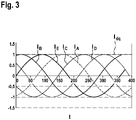
- figure 3 shows current curves, here the phase currents, which are generated with a rotating electrical machine and a sinusoidal phase voltage specification.
- a current I is plotted against time t.
- the individual phase currents I A , I B , I C , I D and I E can be combined to form a space vector.
- the known Clark and Park transformations are used for this.
- the optimal excitation current can be determined metrologically by variation.
- the angle ⁇ indicates the angular difference between the current and voltage vectors, as will be explained in more detail below.
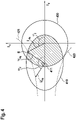
- FIG 4 a current operating point of an electrical machine is shown schematically in a dq coordinate system, specifically by means of what is known as the current locus curve.
- the currents I d and I q are plotted.
- the strategy for controlling this angle difference according to the present method can be explained on the basis of this current locus curve.
- the current operating point B of the electrical machine is shown in the current locus curve. This operating point results from the current vector or the current I dq and the voltage vector, which indicates the voltage U dq and the phase-to-phase flux ⁇ dq .
- the operating point is the common end of the vectors for the current I dq and the linked flux ⁇ dq .
- the operating point B can only be shifted on the so-called voltage circuit, designated 410 here.
- the voltage circuit 410 represents a maximum possible voltage (or, after conversion, the maximum possible concatenated flux), which is used continuously in block operation a required or desired torque results beyond the so-called tipping point or tipping moment, thus only one point of intersection of the stress circle 410 with the line of constant torque, denoted by 421 here.
- 420 designates a maximum or minimum possible torque.
- the pull-out torque represents such a torque, if exceeded, when the current vector I dq runs along the voltage curve, a smaller torque would again result despite the current increase, which would be detrimental to efficiency.
- 400 shows a circle of maximum current, ie for a maximum value of the current I dq , which results from the fact that the lines used in the electric machine or an inverter used cannot carry an infinitely high current. This results in the shaded area shown as the most possible area for the operating point B. In addition, due to block operation, this area is restricted to the boundary line of this hatched area as far as it lies on the voltage circle 410 .
- the midpoint 411 of the voltage circuit 410 (or the voltage ellipse) is determined by the exciter flux in the exciter winding and the d-inductance and can thus be shifted by varying the exciter current, since in the present case it is a separately excited machine. If the excitation current is increased, the voltage circuit 410 shifts to the left. The current vector I dq of the current operating point B thus also shifts. The angle ⁇ I between the current and the d-axis increases and the angle ⁇ U between the voltage and the d-axis decreases.
- the change in the excitation current as a function of the phase position, ie the phase angle, of current and voltage can be derived from this relationship: If the angle ⁇ U between the voltage and the d-axis is larger than the angle ⁇ I between the current and the d-axis, the excitation current is increased; if it is smaller, the excitation current is decreased. Based on this relationship, a controller can be developed that optimizes the excitation current online.
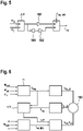
- control deviation is determined from the difference ⁇ between the angle ⁇ U between the voltage and the d-axis and the angle ⁇ I between the current and the d-axis and converted into a setpoint for using the proportional component 501 and integral component 502 (with integrator 503). the excitation current I ex converted.
- an excitation current initial value I ex,init can preferably also be added at the controller output.
- the controller only has to correct a deviation resulting from temperature, machine scattering and/or aging effects, for example.
- the initial value can be measured, for example.
- the control deviation must be adjusted accordingly by 180° or it must be regulated to 180° instead of 0°.
- FIG 6 a sequence of a method according to the invention is shown schematically in a further preferred embodiment.
- the pre-commutation angle ⁇ is regulated based on a required torque M setpoint and the last determined torque M actual .
- the voltage U dq can be calculated using the pre-commutation angle ⁇ . This is converted into the required block pulse pattern in a separate block and the associated signals for the electrical machine are generated, indicated here by U A . . . E , in order to operate electrical machine 100 .
- the phase currents I A...E of the electric machine 100 are measured and converted to I dq values using Clarke and Park transformation. On the one hand, these I dq values are used to calculate the current torque and secondly, to be used together with the voltage values U dq for determining the control deviation or the difference ⁇ .
- the excitation current initial value I ex,init can be read from a lookup table as a function of the voltage U, the required torque M set and the rotor speed n.
- the final excitation current I ex is then determined from these values according to the procedure explained above.
- the excitation current can then be regulated, for example by means of a PWM method using a corresponding excitation voltage U ex .
Landscapes
- Engineering & Computer Science (AREA)
- Power Engineering (AREA)
- Control Of Ac Motors In General (AREA)
- Control Of Eletrric Generators (AREA)
Claims (11)
- Procédé pour faire fonctionner une machine électrique à excitation séparée (100), dans lequel un courant d'excitation (Iex) est réglé comme une grandeur réglante dans le cadre d'une régulation,
caractérisé en ce que la machine électrique (100) est entraînée avec une sélection de blocs,
dans lequel, lorsque la vitesse de rotation (n) de la machine électrique est supérieure à une limite de vitesse de rotation pouvant être prédéfinie, le courant d'excitation (Iex) est augmenté, lorsqu'un angle (ϕU) entre une tension et l'axe d dans le système de coordonnées d-q est supérieur à un angle (ϕI) entre un courant et l'axe d ou à l'angle entre le courant et l'axe d décalé de 180°, et le courant d'excitation (Iex) est réduit lorsque l'angle (ϕU) entre la tension et l'axe d dans le système de coordonnées d-q est inférieur à l'angle (ϕI) entre le courant et l'axe d ou à l'angle entre le courant et l'axe d décalé de 180°. - Procédé selon la revendication 1, dans lequel une différence (Δϕ) entre l'angle (ϕU) entre la tension et l'axe d et l'angle (ϕI) entre le courant et l'axe d dans le système de coordonnées d-q est régulée à une valeur de 0° à 180° en utilisant le courant d'excitation (Iex) comme une grandeur réglante.
- Procédé selon la revendication 2, dans lequel la différence (Δϕ) est régulée à 0° dans un mode moteur et à 180° dans un mode générateur.
- Procédé selon l'une des revendications précédentes, dans lequel la machine électrique (100) est entraînée avec une sélection de blocs au-dessus de la limite de vitesse de rotation et avec une commande PWM en dessous de la limite de vitesse de rotation.
- Procédé selon l'une des revendications précédentes, dans lequel le courant d'excitation (Iex) est réglé comme une grandeur réglante dans le cadre d'une régulation en cascade, en particulier en définissant préalablement une valeur initiale (Iex,init).
- Procédé selon l'une des revendications précédentes, lorsque dépendante de la revendication 2, dans lequel la régulation comprend une partie proportionnelle et/ou intégrale (501, 502).
- Procédé selon l'une des revendications précédentes, dans lequel la tension (Udq) est déterminée en coordonnées d-q sur la base d'un angle de pré-commutation (α) à régler et/ou à réguler.
- Procédé selon la revendication 7, dans lequel l'angle de pré-commutation (α) est réglé et/ou régulé sur la base d'un couple (Msoll) requis par la machine électrique (100) et d'un dernier couple (Mist) déterminé.
- Unité de calcul (140) configurée pour mettre en œuvre un procédé selon l'une des revendications précédentes.
- Programme informatique qui permet à une unité de calcul (140) de mettre en œuvre un procédé selon l'une des revendications 1 à 8, lorsqu'il est exécuté sur l'unité de calcul (140).
- Support de mémoire lisible par machine sur lequel est stocké un programme informatique selon la revendication 10.
Applications Claiming Priority (2)
| Application Number | Priority Date | Filing Date | Title |
|---|---|---|---|
| DE102017216790.4A DE102017216790A1 (de) | 2017-09-22 | 2017-09-22 | Verfahren zum Betreiben einer fremderregten elektrischen Maschine |
| PCT/EP2018/069490 WO2019057361A1 (fr) | 2017-09-22 | 2018-07-18 | Procédé pour faire fonctionner une machine électrique à excitation séparée |
Publications (3)
| Publication Number | Publication Date |
|---|---|
| EP3685504A1 EP3685504A1 (fr) | 2020-07-29 |
| EP3685504B1 true EP3685504B1 (fr) | 2022-07-06 |
| EP3685504B8 EP3685504B8 (fr) | 2022-08-17 |
Family
ID=62952095
Family Applications (1)
| Application Number | Title | Priority Date | Filing Date |
|---|---|---|---|
| EP18742789.3A Active EP3685504B8 (fr) | 2017-09-22 | 2018-07-18 | Procédé pour faire fonctionner une machine électrique à excitation séparée |
Country Status (5)
| Country | Link |
|---|---|
| EP (1) | EP3685504B8 (fr) |
| DE (1) | DE102017216790A1 (fr) |
| ES (1) | ES2927814T3 (fr) |
| HU (1) | HUE060026T2 (fr) |
| WO (1) | WO2019057361A1 (fr) |
Family Cites Families (4)
| Publication number | Priority date | Publication date | Assignee | Title |
|---|---|---|---|---|
| US4949021A (en) * | 1988-11-14 | 1990-08-14 | Sunstrand Corporation | Variable speed constant frequency start system with selectable input power limiting |
| JP4256392B2 (ja) | 2006-01-12 | 2009-04-22 | 三菱電機株式会社 | 車両用発電電動機の制御装置 |
| JP5482574B2 (ja) * | 2010-08-27 | 2014-05-07 | トヨタ自動車株式会社 | 交流電動機の制御システム |
| DE102015117813B4 (de) * | 2014-10-21 | 2025-02-06 | Denso Corporation | Steuerungseinheit und Steuerungsverfahren für rotierende elektrische Maschine |
-
2017
- 2017-09-22 DE DE102017216790.4A patent/DE102017216790A1/de not_active Withdrawn
-
2018
- 2018-07-18 ES ES18742789T patent/ES2927814T3/es active Active
- 2018-07-18 HU HUE18742789A patent/HUE060026T2/hu unknown
- 2018-07-18 EP EP18742789.3A patent/EP3685504B8/fr active Active
- 2018-07-18 WO PCT/EP2018/069490 patent/WO2019057361A1/fr not_active Ceased
Also Published As
| Publication number | Publication date |
|---|---|
| WO2019057361A1 (fr) | 2019-03-28 |
| EP3685504B8 (fr) | 2022-08-17 |
| ES2927814T3 (es) | 2022-11-11 |
| DE102017216790A1 (de) | 2019-03-28 |
| EP3685504A1 (fr) | 2020-07-29 |
| HUE060026T2 (hu) | 2023-01-28 |
Similar Documents
| Publication | Publication Date | Title |
|---|---|---|
| DE102005042777B4 (de) | Motorantriebssteuerungsgerät, Motorantriebssteuerungsverfahren und zugehöriges Programm | |
| DE10120639B4 (de) | Steuersystem für einen Permanentmagnetmotor | |
| DE112011100226T5 (de) | Steuerungsvorrichtung einer Motorantriebsvorrichtung | |
| DE102015117813B4 (de) | Steuerungseinheit und Steuerungsverfahren für rotierende elektrische Maschine | |
| DE112011100096T5 (de) | Steuerungsvorrichtung einer Motorantriebsvorrichtung | |
| DE102011000949A1 (de) | Steuervorrichtung für eine drehende elektrische Maschine | |
| DE112012000830T5 (de) | Antriebssystem für rotierende elektrische Maschine | |
| DE10157257B4 (de) | Toroidal gewickelter Asynchronmotorgenerator mit wählbarer Polzahl | |
| DE102013203505A1 (de) | Verfahren, Systeme und eine Vorrichtung zur Erzeugung von Spannungsbefehlsignalen zur Steuerung eines Betriebes einer elektrischen Maschine | |
| DE112016000455T5 (de) | Steuerungsgerät für eine rotierende elektrische Maschine | |
| EP1504523B1 (fr) | Procede et dispositif de reglage limite par capteur d'une machine synchrone a excitation par aimant permanent | |
| DE102011076999A1 (de) | Verfahren zum Betreiben einer elektrischen Maschine in einem Kraftfahrzeug | |
| EP3695509B1 (fr) | Procédé pour effectuer un changement entre une commande par bloc et une commande par mli d'une machine électrique | |
| DE69617101T2 (de) | Verfahren und System zur Steuerung eines Synchronmotors | |
| EP3028378B1 (fr) | Procédé de mise sous tension et de mise hors tension d'un moteur électrique à n phases dans un véhicule automobile | |
| DE102008052144B4 (de) | Synchronmaschine und Verfahren zum Betreiben einer Synchronmaschine | |
| EP3685504B1 (fr) | Procédé pour faire fonctionner une machine électrique à excitation séparée | |
| EP1504522A1 (fr) | Procede et dispositif pour regler une machine synchrone a excitation par aimant permanent dont les oscillations de puissance sont limitees sur la plage des vitesses de rotation elevees | |
| EP3695508B1 (fr) | Procédé pour faire fonctionner une machine électrique | |
| DE102019212886A1 (de) | Verfahren zum Betreiben einer elektrischen Maschine | |
| EP3292628B1 (fr) | Procédé de mise en marche d'une machine électrique polyphasée dans un véhicule automobile | |
| EP3685503B1 (fr) | Procédé de détermination d'un couple maximal réglable d'une machine électrique | |
| EP1293033B1 (fr) | Commande et regulation de moteurs electriques | |
| DE102024125346A1 (de) | Elektrisches antriebssystem mit statischer gepulster leistungsübertragung | |
| EP3501095B1 (fr) | Procédé de régulation d'une machine synchrone et dispositif de régulation d'une machine synchrone |
Legal Events
| Date | Code | Title | Description |
|---|---|---|---|
| STAA | Information on the status of an ep patent application or granted ep patent |
Free format text: STATUS: UNKNOWN |
|
| STAA | Information on the status of an ep patent application or granted ep patent |
Free format text: STATUS: THE INTERNATIONAL PUBLICATION HAS BEEN MADE |
|
| PUAI | Public reference made under article 153(3) epc to a published international application that has entered the european phase |
Free format text: ORIGINAL CODE: 0009012 |
|
| STAA | Information on the status of an ep patent application or granted ep patent |
Free format text: STATUS: REQUEST FOR EXAMINATION WAS MADE |
|
| 17P | Request for examination filed |
Effective date: 20200421 |
|
| AK | Designated contracting states |
Kind code of ref document: A1 Designated state(s): AL AT BE BG CH CY CZ DE DK EE ES FI FR GB GR HR HU IE IS IT LI LT LU LV MC MK MT NL NO PL PT RO RS SE SI SK SM TR |
|
| AX | Request for extension of the european patent |
Extension state: BA ME |
|
| DAV | Request for validation of the european patent (deleted) | ||
| DAX | Request for extension of the european patent (deleted) | ||
| GRAP | Despatch of communication of intention to grant a patent |
Free format text: ORIGINAL CODE: EPIDOSNIGR1 |
|
| STAA | Information on the status of an ep patent application or granted ep patent |
Free format text: STATUS: GRANT OF PATENT IS INTENDED |
|
| RIC1 | Information provided on ipc code assigned before grant |
Ipc: H02P 25/22 20060101ALI20211221BHEP Ipc: H02P 9/14 20060101ALI20211221BHEP Ipc: H02P 21/00 20160101ALI20211221BHEP Ipc: H02P 25/024 20160101ALI20211221BHEP Ipc: H02P 21/22 20160101AFI20211221BHEP |
|
| INTG | Intention to grant announced |
Effective date: 20220120 |
|
| GRAS | Grant fee paid |
Free format text: ORIGINAL CODE: EPIDOSNIGR3 |
|
| GRAA | (expected) grant |
Free format text: ORIGINAL CODE: 0009210 |
|
| STAA | Information on the status of an ep patent application or granted ep patent |
Free format text: STATUS: THE PATENT HAS BEEN GRANTED |
|
| AK | Designated contracting states |
Kind code of ref document: B1 Designated state(s): AL AT BE BG CH CY CZ DE DK EE ES FI FR GB GR HR HU IE IS IT LI LT LU LV MC MK MT NL NO PL PT RO RS SE SI SK SM TR |
|
| REG | Reference to a national code |
Ref country code: AT Ref legal event code: REF Ref document number: 1503600 Country of ref document: AT Kind code of ref document: T Effective date: 20220715 Ref country code: CH Ref legal event code: EP |
|
| REG | Reference to a national code |
Ref country code: DE Ref legal event code: R096 Ref document number: 502018010100 Country of ref document: DE |
|
| REG | Reference to a national code |
Ref country code: CH Ref legal event code: PK Free format text: BERICHTIGUNG B8 |
|
| REG | Reference to a national code |
Ref country code: IE Ref legal event code: FG4D Free format text: LANGUAGE OF EP DOCUMENT: GERMAN |
|
| RAP2 | Party data changed (patent owner data changed or rights of a patent transferred) |
Owner name: SEG AUTOMOTIVE GERMANY GMBH Owner name: ROBERT BOSCH GMBH |
|
| REG | Reference to a national code |
Ref country code: LT Ref legal event code: MG9D |
|
| REG | Reference to a national code |
Ref country code: NL Ref legal event code: MP Effective date: 20220706 |
|
| REG | Reference to a national code |
Ref country code: ES Ref legal event code: FG2A Ref document number: 2927814 Country of ref document: ES Kind code of ref document: T3 Effective date: 20221111 |
|
| REG | Reference to a national code |
Ref country code: HU Ref legal event code: AG4A Ref document number: E060026 Country of ref document: HU |
|
| PG25 | Lapsed in a contracting state [announced via postgrant information from national office to epo] |
Ref country code: SE Free format text: LAPSE BECAUSE OF FAILURE TO SUBMIT A TRANSLATION OF THE DESCRIPTION OR TO PAY THE FEE WITHIN THE PRESCRIBED TIME-LIMIT Effective date: 20220706 Ref country code: RS Free format text: LAPSE BECAUSE OF FAILURE TO SUBMIT A TRANSLATION OF THE DESCRIPTION OR TO PAY THE FEE WITHIN THE PRESCRIBED TIME-LIMIT Effective date: 20220706 Ref country code: PT Free format text: LAPSE BECAUSE OF FAILURE TO SUBMIT A TRANSLATION OF THE DESCRIPTION OR TO PAY THE FEE WITHIN THE PRESCRIBED TIME-LIMIT Effective date: 20221107 Ref country code: NO Free format text: LAPSE BECAUSE OF FAILURE TO SUBMIT A TRANSLATION OF THE DESCRIPTION OR TO PAY THE FEE WITHIN THE PRESCRIBED TIME-LIMIT Effective date: 20221006 Ref country code: NL Free format text: LAPSE BECAUSE OF FAILURE TO SUBMIT A TRANSLATION OF THE DESCRIPTION OR TO PAY THE FEE WITHIN THE PRESCRIBED TIME-LIMIT Effective date: 20220706 Ref country code: LV Free format text: LAPSE BECAUSE OF FAILURE TO SUBMIT A TRANSLATION OF THE DESCRIPTION OR TO PAY THE FEE WITHIN THE PRESCRIBED TIME-LIMIT Effective date: 20220706 Ref country code: LT Free format text: LAPSE BECAUSE OF FAILURE TO SUBMIT A TRANSLATION OF THE DESCRIPTION OR TO PAY THE FEE WITHIN THE PRESCRIBED TIME-LIMIT Effective date: 20220706 Ref country code: FI Free format text: LAPSE BECAUSE OF FAILURE TO SUBMIT A TRANSLATION OF THE DESCRIPTION OR TO PAY THE FEE WITHIN THE PRESCRIBED TIME-LIMIT Effective date: 20220706 |
|
| PG25 | Lapsed in a contracting state [announced via postgrant information from national office to epo] |
Ref country code: PL Free format text: LAPSE BECAUSE OF FAILURE TO SUBMIT A TRANSLATION OF THE DESCRIPTION OR TO PAY THE FEE WITHIN THE PRESCRIBED TIME-LIMIT Effective date: 20220706 Ref country code: IS Free format text: LAPSE BECAUSE OF FAILURE TO SUBMIT A TRANSLATION OF THE DESCRIPTION OR TO PAY THE FEE WITHIN THE PRESCRIBED TIME-LIMIT Effective date: 20221106 Ref country code: HR Free format text: LAPSE BECAUSE OF FAILURE TO SUBMIT A TRANSLATION OF THE DESCRIPTION OR TO PAY THE FEE WITHIN THE PRESCRIBED TIME-LIMIT Effective date: 20220817 Ref country code: GR Free format text: LAPSE BECAUSE OF FAILURE TO SUBMIT A TRANSLATION OF THE DESCRIPTION OR TO PAY THE FEE WITHIN THE PRESCRIBED TIME-LIMIT Effective date: 20221007 |
|
| REG | Reference to a national code |
Ref country code: CH Ref legal event code: PL |
|
| REG | Reference to a national code |
Ref country code: BE Ref legal event code: MM Effective date: 20220731 |
|
| REG | Reference to a national code |
Ref country code: DE Ref legal event code: R097 Ref document number: 502018010100 Country of ref document: DE |
|
| PG25 | Lapsed in a contracting state [announced via postgrant information from national office to epo] |
Ref country code: SM Free format text: LAPSE BECAUSE OF FAILURE TO SUBMIT A TRANSLATION OF THE DESCRIPTION OR TO PAY THE FEE WITHIN THE PRESCRIBED TIME-LIMIT Effective date: 20220706 Ref country code: RO Free format text: LAPSE BECAUSE OF FAILURE TO SUBMIT A TRANSLATION OF THE DESCRIPTION OR TO PAY THE FEE WITHIN THE PRESCRIBED TIME-LIMIT Effective date: 20220706 Ref country code: MC Free format text: LAPSE BECAUSE OF FAILURE TO SUBMIT A TRANSLATION OF THE DESCRIPTION OR TO PAY THE FEE WITHIN THE PRESCRIBED TIME-LIMIT Effective date: 20220706 Ref country code: LU Free format text: LAPSE BECAUSE OF NON-PAYMENT OF DUE FEES Effective date: 20220718 Ref country code: LI Free format text: LAPSE BECAUSE OF NON-PAYMENT OF DUE FEES Effective date: 20220731 Ref country code: DK Free format text: LAPSE BECAUSE OF FAILURE TO SUBMIT A TRANSLATION OF THE DESCRIPTION OR TO PAY THE FEE WITHIN THE PRESCRIBED TIME-LIMIT Effective date: 20220706 Ref country code: CZ Free format text: LAPSE BECAUSE OF FAILURE TO SUBMIT A TRANSLATION OF THE DESCRIPTION OR TO PAY THE FEE WITHIN THE PRESCRIBED TIME-LIMIT Effective date: 20220706 Ref country code: CH Free format text: LAPSE BECAUSE OF NON-PAYMENT OF DUE FEES Effective date: 20220731 |
|
| PLBE | No opposition filed within time limit |
Free format text: ORIGINAL CODE: 0009261 |
|
| STAA | Information on the status of an ep patent application or granted ep patent |
Free format text: STATUS: NO OPPOSITION FILED WITHIN TIME LIMIT |
|
| PG25 | Lapsed in a contracting state [announced via postgrant information from national office to epo] |
Ref country code: SK Free format text: LAPSE BECAUSE OF FAILURE TO SUBMIT A TRANSLATION OF THE DESCRIPTION OR TO PAY THE FEE WITHIN THE PRESCRIBED TIME-LIMIT Effective date: 20220706 Ref country code: EE Free format text: LAPSE BECAUSE OF FAILURE TO SUBMIT A TRANSLATION OF THE DESCRIPTION OR TO PAY THE FEE WITHIN THE PRESCRIBED TIME-LIMIT Effective date: 20220706 Ref country code: BE Free format text: LAPSE BECAUSE OF NON-PAYMENT OF DUE FEES Effective date: 20220731 |
|
| 26N | No opposition filed |
Effective date: 20230411 |
|
| GBPC | Gb: european patent ceased through non-payment of renewal fee |
Effective date: 20221006 |
|
| PG25 | Lapsed in a contracting state [announced via postgrant information from national office to epo] |
Ref country code: AL Free format text: LAPSE BECAUSE OF FAILURE TO SUBMIT A TRANSLATION OF THE DESCRIPTION OR TO PAY THE FEE WITHIN THE PRESCRIBED TIME-LIMIT Effective date: 20220706 |
|
| PG25 | Lapsed in a contracting state [announced via postgrant information from national office to epo] |
Ref country code: IE Free format text: LAPSE BECAUSE OF NON-PAYMENT OF DUE FEES Effective date: 20220718 |
|
| PG25 | Lapsed in a contracting state [announced via postgrant information from national office to epo] |
Ref country code: SI Free format text: LAPSE BECAUSE OF FAILURE TO SUBMIT A TRANSLATION OF THE DESCRIPTION OR TO PAY THE FEE WITHIN THE PRESCRIBED TIME-LIMIT Effective date: 20220706 |
|
| PG25 | Lapsed in a contracting state [announced via postgrant information from national office to epo] |
Ref country code: GB Free format text: LAPSE BECAUSE OF NON-PAYMENT OF DUE FEES Effective date: 20221006 |
|
| PG25 | Lapsed in a contracting state [announced via postgrant information from national office to epo] |
Ref country code: MK Free format text: LAPSE BECAUSE OF FAILURE TO SUBMIT A TRANSLATION OF THE DESCRIPTION OR TO PAY THE FEE WITHIN THE PRESCRIBED TIME-LIMIT Effective date: 20220706 Ref country code: CY Free format text: LAPSE BECAUSE OF FAILURE TO SUBMIT A TRANSLATION OF THE DESCRIPTION OR TO PAY THE FEE WITHIN THE PRESCRIBED TIME-LIMIT Effective date: 20220706 |
|
| PG25 | Lapsed in a contracting state [announced via postgrant information from national office to epo] |
Ref country code: TR Free format text: LAPSE BECAUSE OF FAILURE TO SUBMIT A TRANSLATION OF THE DESCRIPTION OR TO PAY THE FEE WITHIN THE PRESCRIBED TIME-LIMIT Effective date: 20220706 |
|
| PG25 | Lapsed in a contracting state [announced via postgrant information from national office to epo] |
Ref country code: BG Free format text: LAPSE BECAUSE OF FAILURE TO SUBMIT A TRANSLATION OF THE DESCRIPTION OR TO PAY THE FEE WITHIN THE PRESCRIBED TIME-LIMIT Effective date: 20220706 |
|
| REG | Reference to a national code |
Ref country code: AT Ref legal event code: MM01 Ref document number: 1503600 Country of ref document: AT Kind code of ref document: T Effective date: 20230718 |
|
| PG25 | Lapsed in a contracting state [announced via postgrant information from national office to epo] |
Ref country code: MT Free format text: LAPSE BECAUSE OF FAILURE TO SUBMIT A TRANSLATION OF THE DESCRIPTION OR TO PAY THE FEE WITHIN THE PRESCRIBED TIME-LIMIT Effective date: 20220706 |
|
| PGFP | Annual fee paid to national office [announced via postgrant information from national office to epo] |
Ref country code: ES Payment date: 20240807 Year of fee payment: 7 |
|
| PG25 | Lapsed in a contracting state [announced via postgrant information from national office to epo] |
Ref country code: AT Free format text: LAPSE BECAUSE OF NON-PAYMENT OF DUE FEES Effective date: 20230718 |
|
| PG25 | Lapsed in a contracting state [announced via postgrant information from national office to epo] |
Ref country code: AT Free format text: LAPSE BECAUSE OF NON-PAYMENT OF DUE FEES Effective date: 20230718 |
|
| PGFP | Annual fee paid to national office [announced via postgrant information from national office to epo] |
Ref country code: IT Payment date: 20240718 Year of fee payment: 7 |
|
| PGFP | Annual fee paid to national office [announced via postgrant information from national office to epo] |
Ref country code: HU Payment date: 20250714 Year of fee payment: 8 |
|
| PGFP | Annual fee paid to national office [announced via postgrant information from national office to epo] |
Ref country code: DE Payment date: 20250721 Year of fee payment: 8 |
|
| PGFP | Annual fee paid to national office [announced via postgrant information from national office to epo] |
Ref country code: FR Payment date: 20250717 Year of fee payment: 8 |
|
| PGFP | Annual fee paid to national office [announced via postgrant information from national office to epo] |
Ref country code: AT Payment date: 20260410 Year of fee payment: 5 |