EP3685547B1 - Stromversorgung durch ein optisches system - Google Patents
Stromversorgung durch ein optisches system Download PDFInfo
- Publication number
- EP3685547B1 EP3685547B1 EP18780270.7A EP18780270A EP3685547B1 EP 3685547 B1 EP3685547 B1 EP 3685547B1 EP 18780270 A EP18780270 A EP 18780270A EP 3685547 B1 EP3685547 B1 EP 3685547B1
- Authority
- EP
- European Patent Office
- Prior art keywords
- power
- optical
- network
- optical transceiver
- data
- Prior art date
- Legal status (The legal status is an assumption and is not a legal conclusion. Google has not performed a legal analysis and makes no representation as to the accuracy of the status listed.)
- Active
Links
Images






Classifications
-
- H—ELECTRICITY
- H04—ELECTRIC COMMUNICATION TECHNIQUE
- H04B—TRANSMISSION
- H04B10/00—Transmission systems employing electromagnetic waves other than radio-waves, e.g. infrared, visible or ultraviolet light, or employing corpuscular radiation, e.g. quantum communication
- H04B10/80—Optical aspects relating to the use of optical transmission for specific applications, not provided for in groups H04B10/03 - H04B10/70, e.g. optical power feeding or optical transmission through water
- H04B10/806—Arrangements for feeding power
- H04B10/807—Optical power feeding, i.e. transmitting power using an optical signal
-
- G—PHYSICS
- G02—OPTICS
- G02B—OPTICAL ELEMENTS, SYSTEMS OR APPARATUS
- G02B6/00—Light guides; Structural details of arrangements comprising light guides and other optical elements, e.g. couplings
- G02B6/24—Coupling light guides
- G02B6/42—Coupling light guides with opto-electronic elements
- G02B6/4292—Coupling light guides with opto-electronic elements the light guide being disconnectable from the opto-electronic element, e.g. mutually self aligning arrangements
- G02B6/4293—Coupling light guides with opto-electronic elements the light guide being disconnectable from the opto-electronic element, e.g. mutually self aligning arrangements hybrid electrical and optical connections for transmitting electrical and optical signals
-
- G—PHYSICS
- G06—COMPUTING OR CALCULATING; COUNTING
- G06F—ELECTRIC DIGITAL DATA PROCESSING
- G06F13/00—Interconnection of, or transfer of information or other signals between, memories, input/output devices or central processing units
- G06F13/38—Information transfer, e.g. on bus
- G06F13/40—Bus structure
- G06F13/4063—Device-to-bus coupling
- G06F13/4068—Electrical coupling
-
- H—ELECTRICITY
- H02—GENERATION; CONVERSION OR DISTRIBUTION OF ELECTRIC POWER
- H02J—ELECTRIC POWER NETWORKS; CIRCUIT ARRANGEMENTS OR SYSTEMS FOR SUPPLYING OR DISTRIBUTING ELECTRIC POWER; SYSTEMS FOR STORING ELECTRIC ENERGY
- H02J50/00—Circuit arrangements or systems for wireless supply or distribution of electric power
- H02J50/30—Circuit arrangements or systems for wireless supply or distribution of electric power using light, e.g. lasers
-
- H—ELECTRICITY
- H02—GENERATION; CONVERSION OR DISTRIBUTION OF ELECTRIC POWER
- H02J—ELECTRIC POWER NETWORKS; CIRCUIT ARRANGEMENTS OR SYSTEMS FOR SUPPLYING OR DISTRIBUTING ELECTRIC POWER; SYSTEMS FOR STORING ELECTRIC ENERGY
- H02J50/00—Circuit arrangements or systems for wireless supply or distribution of electric power
- H02J50/80—Circuit arrangements or systems for wireless supply or distribution of electric power involving the exchange of data, concerning supply or distribution of electric power, between transmitting devices and receiving devices
-
- H—ELECTRICITY
- H04—ELECTRIC COMMUNICATION TECHNIQUE
- H04B—TRANSMISSION
- H04B10/00—Transmission systems employing electromagnetic waves other than radio-waves, e.g. infrared, visible or ultraviolet light, or employing corpuscular radiation, e.g. quantum communication
- H04B10/25—Arrangements specific to fibre transmission
-
- H—ELECTRICITY
- H04—ELECTRIC COMMUNICATION TECHNIQUE
- H04B—TRANSMISSION
- H04B10/00—Transmission systems employing electromagnetic waves other than radio-waves, e.g. infrared, visible or ultraviolet light, or employing corpuscular radiation, e.g. quantum communication
- H04B10/40—Transceivers
-
- H—ELECTRICITY
- H04—ELECTRIC COMMUNICATION TECHNIQUE
- H04B—TRANSMISSION
- H04B10/00—Transmission systems employing electromagnetic waves other than radio-waves, e.g. infrared, visible or ultraviolet light, or employing corpuscular radiation, e.g. quantum communication
- H04B10/80—Optical aspects relating to the use of optical transmission for specific applications, not provided for in groups H04B10/03 - H04B10/70, e.g. optical power feeding or optical transmission through water
- H04B10/806—Arrangements for feeding power
-
- H—ELECTRICITY
- H04—ELECTRIC COMMUNICATION TECHNIQUE
- H04B—TRANSMISSION
- H04B10/00—Transmission systems employing electromagnetic waves other than radio-waves, e.g. infrared, visible or ultraviolet light, or employing corpuscular radiation, e.g. quantum communication
- H04B10/80—Optical aspects relating to the use of optical transmission for specific applications, not provided for in groups H04B10/03 - H04B10/70, e.g. optical power feeding or optical transmission through water
- H04B10/806—Arrangements for feeding power
- H04B10/808—Electrical power feeding of an optical transmission system
-
- H—ELECTRICITY
- H04—ELECTRIC COMMUNICATION TECHNIQUE
- H04L—TRANSMISSION OF DIGITAL INFORMATION, e.g. TELEGRAPHIC COMMUNICATION
- H04L12/00—Data switching networks
- H04L12/02—Details
- H04L12/10—Current supply arrangements
-
- H—ELECTRICITY
- H04—ELECTRIC COMMUNICATION TECHNIQUE
- H04L—TRANSMISSION OF DIGITAL INFORMATION, e.g. TELEGRAPHIC COMMUNICATION
- H04L12/00—Data switching networks
- H04L12/02—Details
- H04L12/12—Arrangements for remote connection or disconnection of substations or of equipment thereof
-
- H—ELECTRICITY
- H04—ELECTRIC COMMUNICATION TECHNIQUE
- H04L—TRANSMISSION OF DIGITAL INFORMATION, e.g. TELEGRAPHIC COMMUNICATION
- H04L12/00—Data switching networks
- H04L12/28—Data switching networks characterised by path configuration, e.g. LAN [Local Area Networks] or WAN [Wide Area Networks]
- H04L12/40—Bus networks
- H04L12/40006—Architecture of a communication node
- H04L12/40045—Details regarding the feeding of energy to the node from the bus
-
- H—ELECTRICITY
- H04—ELECTRIC COMMUNICATION TECHNIQUE
- H04L—TRANSMISSION OF DIGITAL INFORMATION, e.g. TELEGRAPHIC COMMUNICATION
- H04L12/00—Data switching networks
- H04L12/28—Data switching networks characterised by path configuration, e.g. LAN [Local Area Networks] or WAN [Wide Area Networks]
- H04L12/40—Bus networks
- H04L12/40052—High-speed IEEE 1394 serial bus
- H04L12/40091—Bus bridging
-
- H—ELECTRICITY
- H04—ELECTRIC COMMUNICATION TECHNIQUE
- H04L—TRANSMISSION OF DIGITAL INFORMATION, e.g. TELEGRAPHIC COMMUNICATION
- H04L12/00—Data switching networks
- H04L12/28—Data switching networks characterised by path configuration, e.g. LAN [Local Area Networks] or WAN [Wide Area Networks]
- H04L12/40—Bus networks
- H04L12/40169—Flexible bus arrangements
- H04L12/40176—Flexible bus arrangements involving redundancy
-
- H—ELECTRICITY
- H04—ELECTRIC COMMUNICATION TECHNIQUE
- H04M—TELEPHONIC COMMUNICATION
- H04M19/00—Current supply arrangements for telephone systems
- H04M19/08—Current supply arrangements for telephone systems with current supply sources at the substations
-
- G—PHYSICS
- G01—MEASURING; TESTING
- G01J—MEASUREMENT OF INTENSITY, VELOCITY, SPECTRAL CONTENT, POLARISATION, PHASE OR PULSE CHARACTERISTICS OF INFRARED, VISIBLE OR ULTRAVIOLET LIGHT; COLORIMETRY; RADIATION PYROMETRY
- G01J3/00—Spectrometry; Spectrophotometry; Monochromators; Measuring colours
- G01J3/02—Details
- G01J3/0205—Optical elements not provided otherwise, e.g. optical manifolds, diffusers, windows
- G01J3/0218—Optical elements not provided otherwise, e.g. optical manifolds, diffusers, windows using optical fibers
-
- G—PHYSICS
- G02—OPTICS
- G02B—OPTICAL ELEMENTS, SYSTEMS OR APPARATUS
- G02B6/00—Light guides; Structural details of arrangements comprising light guides and other optical elements, e.g. couplings
- G02B6/24—Coupling light guides
- G02B6/36—Mechanical coupling means
- G02B6/38—Mechanical coupling means having fibre to fibre mating means
- G02B6/3807—Dismountable connectors, i.e. comprising plugs
- G02B6/381—Dismountable connectors, i.e. comprising plugs of the ferrule type, e.g. fibre ends embedded in ferrules, connecting a pair of fibres
- G02B6/3817—Dismountable connectors, i.e. comprising plugs of the ferrule type, e.g. fibre ends embedded in ferrules, connecting a pair of fibres containing optical and electrical conductors
-
- H—ELECTRICITY
- H02—GENERATION; CONVERSION OR DISTRIBUTION OF ELECTRIC POWER
- H02S—GENERATION OF ELECTRIC POWER BY CONVERSION OF INFRARED RADIATION, VISIBLE LIGHT OR ULTRAVIOLET LIGHT, e.g. USING PHOTOVOLTAIC [PV] MODULES
- H02S40/00—Components or accessories in combination with PV modules, not provided for in groups H02S10/00 - H02S30/00
- H02S40/30—Electrical components
- H02S40/38—Energy storage means, e.g. batteries, structurally associated with PV modules
-
- Y—GENERAL TAGGING OF NEW TECHNOLOGICAL DEVELOPMENTS; GENERAL TAGGING OF CROSS-SECTIONAL TECHNOLOGIES SPANNING OVER SEVERAL SECTIONS OF THE IPC; TECHNICAL SUBJECTS COVERED BY FORMER USPC CROSS-REFERENCE ART COLLECTIONS [XRACs] AND DIGESTS
- Y02—TECHNOLOGIES OR APPLICATIONS FOR MITIGATION OR ADAPTATION AGAINST CLIMATE CHANGE
- Y02D—CLIMATE CHANGE MITIGATION TECHNOLOGIES IN INFORMATION AND COMMUNICATION TECHNOLOGIES [ICT], I.E. INFORMATION AND COMMUNICATION TECHNOLOGIES AIMING AT THE REDUCTION OF THEIR OWN ENERGY USE
- Y02D30/00—Reducing energy consumption in communication networks
- Y02D30/50—Reducing energy consumption in communication networks in wire-line communication networks, e.g. low power modes or reduced link rate
-
- Y—GENERAL TAGGING OF NEW TECHNOLOGICAL DEVELOPMENTS; GENERAL TAGGING OF CROSS-SECTIONAL TECHNOLOGIES SPANNING OVER SEVERAL SECTIONS OF THE IPC; TECHNICAL SUBJECTS COVERED BY FORMER USPC CROSS-REFERENCE ART COLLECTIONS [XRACs] AND DIGESTS
- Y02—TECHNOLOGIES OR APPLICATIONS FOR MITIGATION OR ADAPTATION AGAINST CLIMATE CHANGE
- Y02E—REDUCTION OF GREENHOUSE GAS [GHG] EMISSIONS, RELATED TO ENERGY GENERATION, TRANSMISSION OR DISTRIBUTION
- Y02E10/00—Energy generation through renewable energy sources
- Y02E10/50—Photovoltaic [PV] energy
-
- Y—GENERAL TAGGING OF NEW TECHNOLOGICAL DEVELOPMENTS; GENERAL TAGGING OF CROSS-SECTIONAL TECHNOLOGIES SPANNING OVER SEVERAL SECTIONS OF THE IPC; TECHNICAL SUBJECTS COVERED BY FORMER USPC CROSS-REFERENCE ART COLLECTIONS [XRACs] AND DIGESTS
- Y02—TECHNOLOGIES OR APPLICATIONS FOR MITIGATION OR ADAPTATION AGAINST CLIMATE CHANGE
- Y02E—REDUCTION OF GREENHOUSE GAS [GHG] EMISSIONS, RELATED TO ENERGY GENERATION, TRANSMISSION OR DISTRIBUTION
- Y02E70/00—Other energy conversion or management systems reducing GHG emissions
- Y02E70/30—Systems combining energy storage with energy generation of non-fossil origin
Definitions
- the present disclosure relates generally to communications networks, and more particularly, to power delivery in a communications network.
- PoE Power over Ethernet
- PSE power sourcing equipment
- PD powered device
- PoE Power over Ethernet
- PSE power sourcing equipment
- PD powered device
- PoE power is delivered over the cables used by the data over a range from a few meters to about one hundred meters.
- PSE power sourcing equipment
- PD powered device
- PoE power must be supplied through a local power source such as a wall outlet due to limitations with conventional PoE.
- today's PoE systems have limited power capacity, which may be inadequate for many classes of devices.
- US 2015/078740 A1 discloses a fiber optic-based communications network including: a power insertion device, connected to multiple fiber links from a data source, configured to provide power insertion to a hybrid fiber/power cable connected to at least one fiber link of the multiple fiber links; the hybrid fiber/power cable, connecting the power insertion device to a connection interface device, configured to transmit data and power from the power insertion device to the connection interface device; and the connection interface device, configured to provide an interface for connection to an end device via a power over Ethernet (PoE)-compatible connection and to provide optical to electrical media conversion for data transmitted from the power insertion device to an end device via the hybrid fiber/power cable and the PoE-compatible connection.
- PoE power over Ethernet
- PoE Power over Ethernet
- the embodiments described herein provide power delivery through an optical transceiver by supplying power integrated with fiber cabling over the same fiber/optical transceiver system so that power may be supplied at greater distances (e.g., up to 10 km), in greater quantity (e.g., up to several kilowatts), and may be provided in locations where local power is difficult to deliver.
- power may be supplied at greater distances (e.g., up to 10 km), in greater quantity (e.g., up to several kilowatts), and may be provided in locations where local power is difficult to deliver.
- power does not need to be supplied throughout a data center room and a full zoned system may be deployed without building out a data room.
- the embodiments effectively deliver communications and power on a large enough scale that equipment in a data room can entirely be powered from an equipment/premise entrance point of the building.
- electrical power distribution equipment may be removed from the floor data room and switches, routers, access points, lighting systems, and other electronic devices or equipment may be placed outside of the 100 m range of traditional PoE systems.
- power can be delivered to equipment in a zone, data room on a floor, or an access point anywhere in the building.
- IoT Internet of Things
- networks e.g., switch/router
- PoE + Fiber The system is referred to herein as PoE + Fiber (PoE+F).
- the embodiments operate in the context of a data communications network including multiple network devices.
- the network may include any number of network devices in communication via any number of nodes (e.g., routers, switches, gateways, controllers, access points, or other network devices), which facilitate passage of data within the network.
- nodes e.g., routers, switches, gateways, controllers, access points, or other network devices
- the network devices may communicate over or be in communication with one or more networks (e.g., local area network (LAN), metropolitan area network (MAN), wide area network (WAN), virtual private network (VPN) (e.g., Ethernet virtual private network (EVPN), layer 2 virtual private network (L2VPN)), virtual local area network (VLAN), wireless network, enterprise network, corporate network, data center, Internet of Things (IoT), Internet, intranet, or any other network).
- networks e.g., local area network (LAN), metropolitan area network (MAN), wide area network (WAN), virtual private network (VPN) (e.g., Ethernet virtual private network (EVPN), layer 2 virtual private network (L2VPN)), virtual local area network (VLAN), wireless network, enterprise network, corporate network, data center, Internet of Things (IoT), Internet, intranet, or any other network).
- networks e.g., local area network (LAN), metropolitan area network (MAN), wide area network (WAN), virtual private network (VPN) (e.g., Ethernet virtual private network (EV
- the network is configured to pass electrical power along with optical data to provide both data connectivity and electric power to network devices such as switches, routers, access points, or other electronic components and devices. Signals may be exchanged among communications equipment and power transmitted from power sourcing equipment to powered devices.
- the PoE+F system delivers power to and from a network (e.g., switch/router system) using an optical transceiver (optical module) configured to receive and transmit both data and electrical power, and a cabling system comprising both optical fibers and electrical wires (e.g., copper wires).
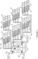
- the PoE+F system uses building power supplied to a network device 10, which may be located in a premise/entry room, for example.
- the power may be transmitted from the building entry point to end points, which may be located at distances greater than 100 meters (e.g., 1 km, 10 km, or any other distance), and/or at greater power levels than 100 Watts (e.g., 250 Watts, 1000 Watts or any other power level).
- the network device 10 comprises a power supply unit (PSU) 11 for receiving power (e.g., building power), a fabric 12, and a plurality of line cards 13.
- PSU power supply unit
- one of the line cards receives fiber from outside of the building (e.g., from street or other location) and the other line cards implement PoE+F.
- the network device 10 is operable to provide high capacity power from an internal power system (e.g., PSU providing over and including 5 kW (e.g., 10 kW, 12 kW, 14 kW, 16 kW), or PSU providing over and including 100 W (e.g., 500 W, 1 kW) of useable power or any other suitable power capacity).
- the PSU 11 may provide, for example, PoE, pulsed power, or AC power.
- the network device 10 is operable to receive power external from a communications network and transmit the power over data fiber cables 18 in the communications network (e.g., network comprising central hub 10 (PSE) and a plurality of network devices 14, 15 (PDs).
- the network device 10 may comprise, for example, a router or convergence device (e.g., Network Convergence System (NCS) 4000 series available from Cisco Systems, Inc.) or any other suitable line card system. It is to be understood that this is only an example and any other network device operable to transmit power and optical data may be used.
- One or more of the line cards 13 may also include an optical transceiver module 16 operable to transmit power and data on the cables 18.
- the network may include any number or arrangement of network communications devices (e.g., switches 14, access points 15, routers, or other devices operable to route (switch, forward) data communications).
- each group of access points 15 is located on a different floor or zone.
- One or more network devices 14, 15 may also deliver power to equipment using PoE, as described below with respect to Figures 3 and 4 .
- one or more of the network devices 14, 15 may deliver power using PoE to electronic components such as IP (Internet Protocol) cameras, VoIP (Voice over IP) phones, video cameras, point-of-sale devices, security access control devices, residential devices, building automation devices, industrial automation, factory equipment, lights (building lights, streetlights), traffic signals, and many other electrical components and devices.
- IP Internet Protocol
- VoIP Voice over IP
- Cables 18 extending from the network device 10 to the switches 14 and access points 15 are configured to transmit power over data fiber cabling and include both optical fibers and electrical wires.
- the cables 18 comprise two copper wires and two fibers.
- the cables 18 may be formed from any material suitable to carry both electrical power and optical data (e.g., copper, fiber) and may carry any number of electrical wires and optical fibers in any arrangement. As described below with respect to Figures 15 -18, the cables 18 may also include cooling.
- optical transceivers optical module, optical device, optics module, transceiver, silicon photonics optical transceiver 16 are configured to source or receive power, as described in detail below.
- the transceiver modules 16 operate as an engine that bidirectionally converts optical signals to electrical signals or in general as an interface to the network element copper wire or optical fiber.
- the optical transceiver 16 may be a pluggable transceiver module in any form factor (e.g., SFP (Small Form-Factor Pluggable), QSFP (Quad Small Form-Factor Pluggable), CFP (C Form-Factor Pluggable), and the like), and may support data rates up to 400 Gbps, for example.
- Hosts for these pluggable optical modules include line cards on the switches 14, access points 15, or other network devices.
- One or more of the line cards 13 in network device 10 may also host optical modules.
- the host may include a printed circuit board (PCB) and electronic components and circuits operable to interface telecommunications lines in a telecommunications network.
- the host may be configured to perform one or more operations and receive any number or type of pluggable transceiver modules configured for transmitting and receiving signals.
- PCB printed circuit board
- the optical transceiver 16 may also be configured for operation with AOC (Active Optical Cable) and form factors used in UWB (Ultra-Wideband) applications, including for example, Ultra HDMI (High-Definition Multimedia Interface), serial high bandwidth cables (e.g., thunderbolt), and other form factors.
- AOC Active Optical Cable
- UWB Ultra-Wideband
- form factors used in UWB (Ultra-Wideband) applications, including for example, Ultra HDMI (High-Definition Multimedia Interface), serial high bandwidth cables (e.g., thunderbolt), and other form factors.
- optical transceivers 16 may be configured for operation in point-to-multipoint or multipoint-to-point topology.
- QFSP may breakout to SFP+.
- One or more embodiments may be configured to allow for load shifting.
- the optical transceiver 16 is modified along with a fiber connector system to incorporate copper wires to deliver power through the optical transceiver to the powered devices 14, 15 for use by the network communications devices.
- the optical transceiver 16 provides for power to be delivered to the switches 14 and access points 15 in locations where standard power is not available.
- the optical transceiver 16 may be configured to tap some of the energy and make intelligent decisions so that the power source 10 knows when it is safe to increase power on the wires without damaging the system or endangering an operator.
- one or more network devices may comprise dual-role power ports that may be selectively configurable to operate as a PSE (Power Source Equipment) port to provide power to a connected device or as a PD (Powered Device) port to sink power from the connected device, and enable the reversal of energy flow under system control, as described in U.S. Patent No. 9,531,551 ("Dynamically Configurable Power-Over-Ethernet Apparatus and Method", issued December 27, 2016 ), for example.
- the dual-role power ports may be PoE or PoE+F ports, for example.
- the network may also include one or more network devices comprising conventional optical modules that only process and transmit the optical data. These network devices would receive electrical power from a local power source such as a wall outlet. Similarly, specialized variants of transceivers 16 could eliminate the optical data interfaces, and only interconnect power (perhaps moving data interconnection to wireless networks).
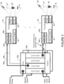
- FIG. 2 illustrates a redundant data and power PoE+F system.
- the network includes two redundant network devices 20a, 20b, which receive power and fiber at a premise entrance point, as previously described.
- Each network device 20a, 20b delivers power over data fiber cabling 28a, 28b, respectively, to the switches 24 and access points 25.
- Each switch 24 and access point 25 comprises two optical transceivers 26a, 26b for receiving data and power from network devices 20a, 20b, respectively.
- the network shown in the example of Figure 2 provides backup data and power in the case of failure of any single cable 28a, 28b, or either network device 20a, 20b, or provide additional power or bandwidth as needed in the network.
- a plurality of switches 24 and access points 25 may provide power and data to a first circuit and another group of switches and access points may provide power and data to a second circuit. Both circuits may be used to provide power to an equipment power circuit, for example, to provide higher service availability.
- FIG. 3 illustrates an example of PoE+F in a fog node deployment, in accordance with one embodiment.
- Fog is an IoT technique where computation, networking, and storage are moved from the cloud to locations much closer to the IoT sensors and actuators.
- power is delivered over data fiber cables 38a, 38b connected to optical transceivers 36a, 36b.
- Each network device 30a, 30b provides power delivered over data fiber cabling 38a, 38b to any number of fog nodes 32.
- power may be delivered over data fiber cabling to provide approximately 600 W output to each of the twenty-four fog nodes 32.
- Each fog node 32 comprises processing and memory 33 and one or more PoE modules 34 operable to power one or more PoE devices.
- each fog node 32 may provide approximately 500 W of power to PoE devices such as streetlights 31, traffic signals 35, 5G cells, access points, base stations 37, video cameras 39, or any other electronic device serving a smart building or smart city.
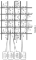
- FIG. 4 illustrates an example of smart city fog deployment, in accordance with one embodiment.
- two PoE+F redundant routers 40 provide primary and backup (redundant) power and data to fog nodes 42.
- the fog nodes 42 provide power to one or more IoT (Internet of Things) devices 45 (e.g., 5G cells, APs, streetlights, traffic signals, video cameras, or other devices).
- IoT Internet of Things
- each pair of routers 40 may serve approximately twenty-four fog nodes 42, covering approximately 100 city blocks or approximately 1 square km.
- the PoE fog node arrangement shown in Figures 3 and 4 may also be used in a smart building (e.g., different fog node for each floor), smart factory (e.g., different fog node for each assembly cell), cruise ship, hotel, school, campus, hospital, shopping center, or any other environment.
- a smart building e.g., different fog node for each floor
- smart factory e.g., different fog node for each assembly cell
- cruise ship hotel, school, campus, hospital, shopping center, or any other environment.
- the network devices and topologies shown in Figures 1 , 2 , 3 , and 4 , and described above are only examples and the embodiments described herein may be implemented in networks comprising different network topologies or network devices, without departing from the scope of the embodiments.
- the network may comprise any number or type of network communications devices that facilitate passage of data over the network (e.g., routers, switches, gateways, controllers), network elements that operate as endpoints or hosts (e.g., servers, virtual machines, clients), and any number of network sites or domains in communication with any number of networks.
- network nodes may be used in any suitable network topology, which may include any number of servers, virtual machines, switches, routers, or other nodes interconnected to form a large and complex network, which may include cloud or fog computing.
- Nodes may be coupled to other nodes or networks through one or more interfaces employing any suitable wired or wireless connection, which provides a viable pathway for electronic communications.
- FIG 5 is a flowchart illustrating an overview of a process for delivering power and data through an optical transceiver system.
- power and data are received at an optical transceiver 16 operating at a network device 14, wherein the power is delivered to the optical transceiver over data fiber cable 18 and received at a connector configured to transmit the power and data from the cable to the optical transceiver ( Figure 1 ).
- the optical transceiver 16 transmits power and data to the network device 14, which is powered by the power received at the optical transceiver (step 52) ( Figures 1 and 5 ).
- the network device may further transmit PoE to one or more PoE devices (e.g., lights, access points, streetlights, traffic signals, cameras, or other devices) (step 54).
- PoE devices e.g., lights, access points, streetlights, traffic signals, cameras, or other devices
- an optical transceiver 16 at the central hub 10 is operable to transmit power received from the power supply unit 11 along with data on the power and fiber cable 18 ( Figure 1 ).
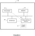
- Figure 6 illustrates an example of a network device 60 (e.g., switch 14, access point 15, central hub 10 in Figure 1 ) that may be used to implement the embodiments described herein.
- the network device 60 is a programmable machine that may be implemented in hardware, software, or any combination thereof.
- the network device 60 includes one or more processors 62, memory 64, interface 66, and PoE+F optical module 68 (e.g., optical transceiver 16 in Figure 1 ).
- Memory 64 may be a volatile memory or non-volatile storage, which stores various applications, operating systems, modules, and data for execution and use by the processor 62.
- components of the PoE+F optical module 68 e.g., code, logic, or firmware, etc.
- the network device 60 may include any number of memory components.
- the network device 60 may include any number of processors 62 (e.g., single or multi-processor computing device or system), which may communicate with a forwarding engine or packet forwarder operable to process a packet or packet header.
- the processor 62 may receive instructions from a software application or module, which causes the processor to perform functions of one or more embodiments described herein.
- Logic may be encoded in one or more tangible media for execution by the processor 62.
- the processor 62 may execute codes stored in a computer-readable medium such as memory 64.
- the computer-readable medium may be, for example, electronic (e.g., RAM (random access memory), ROM (read-only memory), EPROM (erasable programmable read-only memory)), magnetic, optical (e.g., CD, DVD), electromagnetic, semiconductor technology, or any other suitable medium.
- the computer-readable medium comprises a non-transitory computer-readable medium.
- Logic may be used to perform one or more functions described above with respect to the flowchart of Figure 5 or other functions such as power level negotiations or safety subsystems described below.
- the network device 60 may include any number of processors 62.
- the interface 66 may comprise any number of interfaces or network interfaces (line cards, ports, connectors) for receiving data or power, or transmitting data or power to other devices.
- the network interface may be configured to transmit or receive data using a variety of different communications protocols and may include mechanical, electrical, and signaling circuitry for communicating data over physical links coupled to the network or wireless interfaces.
- line cards may include port processors and port processor controllers.
- the interface 66 may be configured for PoE+F, PoE, PoF, or similar operation.
- the PoE+F optical module 68 may comprise one or more components of the optical transceiver 16 in Figure 1 and may also include logic, firmware, software, etc. for use with a smart optical module shown in Figures 7 and 8 (described below).
- the optical module 68 may comprise hardware or software for use in power detection, power monitor and control, or power enable/disable.
- the optical module 68 may further comprise one or more of the processor or memory components, or interface for receiving power and optical data from the cable 18 at a fiber connector, for delivering power and signal data to the network device, or transmitting control signals to the power source 10, for example ( Figures 1 and 6 ).
- power is supplied to the optical module by power supply 67 and the PoE+F optical module 68 provides power to the rest of the components at the network device 60.
- network device 60 shown in Figure 6 and described above is only an example and that different configurations of network devices may be used.
- the network device 60 may further include any suitable combination of hardware, software, algorithms, processors, devices, components, or elements operable to facilitate the capabilities described herein.
- FIG. 7 illustrates a smart optical transceiver 70, in accordance with one embodiment.
- the smart optical transceiver 70 provides for communication with the power source (e.g., network device 10 in Figure 1 ) during power up of the powered device and may provide fault protection and detection.
- the device 70 is configured to calculate available power and prevent the cabling system from being energized when it should not be powered.
- the optical device 70 includes optical components 72 for receiving optical data and converting it to electrical signals (or converting electrical signals to optical data) and power components including power detection module 74, power monitor and control unit 76, and power enable/disable module 78.
- Pulsed power or advanced PoE driving voltages beyond 60V up to +/-450V may create electromagnetic interference with the optical circuitry 72.
- the power components 74, 76, 78 are isolated from the optical components 72 via an isolation component 79 (e.g., isolation material or element).
- the isolation component 79 electromagnetically isolates the power circuit from the optical components 72 to prevent interference with operation of the optics.
- the power detection module 74 is operable to detect power, energize the optical components 72, and return a message to the power source for fiber or the powered cabling.
- the return message may be provided via state changes on the power wires or over the optical channel.
- the power is not enabled by the power enable/disable module 78 until the optical transceiver 70 and the source have determined that the device is properly connected and the network device to be powered is ready to be powered.
- the power monitor and control device 76 continuously monitors power delivery to ensure that the system can support the needed power delivery, and no safety limits (voltage, current) are exceeded.
- the power monitor and control device 76 may also monitor optical signaling and disable power if there is a lack of optical transitions or communication with the power source.
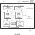
- FIG 8 illustrates an example of the smart optical transceiver of Figure 7 with auto power negotiation for PoE or pulsed power, in accordance with one embodiment.
- the system 80 includes optical components 82 and power components including power monitor and control 86 and power enable/disable 88.
- the device 80 includes an auto detection module 85 that operates with a pulse power detection module 83 and PoE detection module 84.
- Each module 83, 84 is connected to its own power monitor and control module 86 and power enable; disable module 88.
- the circuit detects the type of power applied to the device 80, determines if PoE or pulsed power is a more efficient power delivery method, and then uses the selected power delivery mode. Additional modes may support other power + data standards (e.g., USB (Universal Serial Bus)).
- USB Universal Serial Bus
- the optical transceiver may comprise different types of optical transceivers, including for example, an optical transceiver module or silicon photonics optical transceiver.
- optical transceiver as used herein may refer to any type of optical component, module, or device operable to receive and transmit optical signals.
- Figures 11A-11B illustrate an example of an optical module configured to contact an electrical interface plate on a modified fiber connector ( Figures 10A-10B ) and pass power through an optical module cage system ( Figures 12A-12B ), as shown in the assembly of Figure 13 . It is to be understood that the optical transceivers shown in Figures 11A and 11B are only examples and that other optical devices configured to receive and transmit power and data may be used to implement PoE+F without departing from the scope of the embodiments.
- the connector may comprise, for example, a modified LC (Local Connector, Lucent Connector) generally corresponding to a standard LC format.
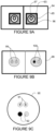
- the cable 90 includes two data fibers 91 and two electrical wires 92 (e.g., copper, aluminum, metal) enclosed in a cable jacket.
- the copper wires may be 18 AWG (American Wire Gauge) or another size/capacity (e.g., 10 AWG), or any other suitable size or capacity according to any applicable standard.
- the copper wires 92 may be bonded separately to the optical connector, which allows a modified LC connector system to be implemented without extending a bulkhead connection. As described below, a crimp system may be used to connect the copper wires 91 to the respective plus/minus (plus/return, power/return) connections. It is to be understood that the optical fiber and electrical wire arrangement of the cable 90 shown in Figure 9C is only an example.
- the cable may include any number of optical fibers 91 or electrical wires 92 in any arrangement.
- the cable may include additional data fibers or power wires as described below with respect to a modified MPO (Multi-fiber Push On/Pull Off) connector shown in Figures 16A, 16B, 17A, and 17B.
- the cable may also include cooling as described below with respect to Figure 15 .
- chassis ground is on an outer case 95
- copper (metal) contact 96 for power is on the outside of a ferrule 93
- fiber 97 is inside the ferrule.
- the outer housing 95 is metalized for digital ground and the outer ferrule 96 is metalized for power.
- Data fiber 97 is in ferrule 93, as with conventional LC connectors.
- ground may be connected on one side of the dual connector at the outer ferrule instead of the outer case on both sides of the connector.
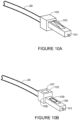
- Figures 10A and 10B illustrate details of one example of an LC connector 102 modified to include an external contact plate and a crimp point for which electrical wires can be crimped onto the connector.
- the connector 102 includes a latch mechanism 103 on an upper side that allows the connector to be easily engaged and disengaged.
- the connector 102 mechanically couples and aligns the fibers in ferrule 101 so that light can pass through to the optical transceiver.
- the modified connector 102 receives a cable (e.g., cable 90 shown in Figure 9C ) comprising optical fiber (or fibers) and power wire (or wires).
- the connector 102 further comprises an external metal contact plate (e.g., one or more copper pads) 106 and crimp point 107 onto which the copper wire can be crimped.
- the optical module includes an internal electrical input (e.g., tab or wire contact) for interface with the contact plate 106.
- a portion 108 of the connector body may be extended to allow for the copper wire to be crimped using a standard press-in crimp method.
- the housing 108 is elongated to support 10, 12, 14, 16, or 18 AWG wire systems.
- a spring loaded slide cover 109 may be provided to cover the electrical contact point 106 as the connector is removed from the optical device to prevent energized cable from becoming grounded during handling. The cover 109 is pushed back during insertion of the connector 102 into the optical device, thereby allowing mating contact between the external contact plate 106 and the internal contact point on the optical module when the connector is inserted. If the optical device is not configured to receive power (conventional non-power LC connector), communications compatibility is maintained through the common LC connector interface.
- FIGS 10A and 10B are only an example and that other connectors or configurations may be used without departing from the scope of the embodiments.
- an MPO Multi-fiber Push On/Pull Off
- a single fiber system is shown in Figures 10A and 10B , however, two LC connectors in a duplex fiber system may be used as previously described with respect to Figures 9A and 9B to provide for a power wire and a return wire to interconnect with the optical device.
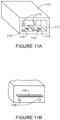
- Figures 11A and11B illustrate an example of an optical module 110 configured to receive power from the modified LC connector 102 of Figure 10B and pass the power through the optical module.
- the optical module 110 includes an opening 111 configured for receiving two connectors 102 at a front end ( Figures 10A and 11A ).
- a rear wall of the opening 111 includes fiber inputs 112.
- the optical module 110 further includes internal electrical input contacts (power tabs, wires, angled spring fingers) 113 for contact with the connector external power pad 106 ( Figures 10B and 11A ).
- the optical device 110 sources power or receives power through these contact points 113.
- the system is configured to handle PoE class 8 systems (up to 100W), as well as other power distribution systems such as pulsed power.
- the optical module 110 may include keying to prevent insertion of certain types of cables into incompatible modules.
- a hook/post arrangement 114 is used to slide the protective cover 109 out of the way to allow for contact between the external contact plate 106 on the connector 102 and the internal electrical power input tab 113 on the optical module 110.
- two female receptacles 116 are provided to connect to the system module cage ( Figure 12B ), along with the electrical signal interface 118 for data and control. If different types of modules are used for PD and PSE interfaces, one may include male pins and the other female sockets. The use of female connectors for power at the rear of the module allows for the module to be accidentally removed under power without damaging anything or anyone.
- the power output points 116 may be located on a lower portion of the optical device 110 as shown in Figure 11B or an upper portion of the device.
- FIGs 12A-12B illustrate an example of an optical module cage 120 for the optical module shown in Figures 11A-11B .
- the optical module cage 120 may include cage ground points 121 and air flow openings 125, for example.
- the cage is modified to include two male power posts 122 (+, return) for mating with the female receptacles 116 on the optical module ( Figures 11B and 12B ).
- the rear wall further includes an opening 128 with contacts for receiving electrical signal interface 118.
- the module cage interface may also include keying to prevent a mismatch between incompatible components.
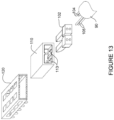
- Figure 13 is an exploded view showing the fiber and power cable 90, connectors 102, optical module 110, and optical module cage 120, in accordance with one embodiment.
- the cable 130 includes two optical fibers 104 and two power wires 105 for connection with the modified LC connector 102 comprising power pads added to a bottom of the connector and a crimping mechanism to allow for attachment of the copper wires 105, as shown in Figure 10B .
- the modified optical module 110 passes through the power received at electrical contact points 113 from the connector 102 to the optical module cage 120, which passes power through to the circuit board (e.g., line card, route processor, fabric card).
- the circuit board e.g., line card, route processor, fabric card
- FIG 14 is a cross-sectional view of a cable design incorporating fiber, power, and cooling.
- a cable 140 includes two data fibers 142, two copper wires 144, and two cooling pipes 146.
- the cooling lines may, for example, deliver water, refrigerant, or high pressure air to the powered device and powered equipment.
- the system may be used to provide cooling to devices and equipment in remote areas where traditional cooling is not available.
- the cable jacket 148 may provide additional insulation, along with insulation on the cooling pipes 146 to provide effective cooling over a 10 km reach, for example.
- FIG. 15 illustrates an example of a connector cable assembly comprising power, fiber, and cooling, in accordance with one embodiment.
- a connector e.g., modified MPO connector
- Press crimp interconnectors may be used to terminate power, ground, and shield, as previously described.
- the example shown in Figure 15 includes two chassis grounds 152, two signal grounds 153, and two optical fibers 155.
- Power 154 may include one connection or two or more pins/mates.
- the cable may also include cooling pipes (e.g., two cooling pipes and two return pipes) (not shown).
- the connector cable assembly may also be configured to include additional fibers (e.g., from two to twenty-four fibers).
- Figure 16 shows another example of a connector 160.
- the optical transceiver 161 is shown with power control circuits 165 and optical to electrical power conversion module 167.
- the connector 160 and optical module 161 are configured for six power fibers 164 and two optical fibers 165 for data.
- power is delivered optically over fibers 164.
- the connector cable assembly shown in Figure 16 may comprise any number or combination of power and optical fibers.
- Figure 17 illustrates the smart optical device of Figure 7 with cooling pass-through lines.
- the optical device 170 includes optical components 172, power detection 174, power monitor and control 176, and power enable/disable 178.
- the optical device 170 may also include additional components shown in Figure 8 , for example.
- the cooling pipes 177 provide cooling to the powered equipment and return cooling.
- a cooling tap 175 is also provided for the optical module 170.
- the optical module cage passes the cooling through to the system and returns the heat generated within the optical components 172 out through the module and into the coolant.
- one or more embodiments may allow for lengths from a building entry point to end points of up to 10 km.
- Network communications devices such as routers, switches, and access points, and electronic devices such as lighting systems and other applications may be located outside of the 100 m range of traditional PoE systems. This allows all electrical power to be removed from floor data rooms.
- Use of a modified connector system allows for fiber compatibility between systems where one or both sides may not be using power over copper delivery to power network equipment.
- the connector assembly may be configured for operation with PoE+F optical systems or conventional non-power optical systems.
Landscapes
- Engineering & Computer Science (AREA)
- Computer Networks & Wireless Communication (AREA)
- Signal Processing (AREA)
- Physics & Mathematics (AREA)
- Electromagnetism (AREA)
- Optics & Photonics (AREA)
- General Physics & Mathematics (AREA)
- Power Engineering (AREA)
- General Engineering & Computer Science (AREA)
- Theoretical Computer Science (AREA)
- Computer Hardware Design (AREA)
- Optical Communication System (AREA)
- Small-Scale Networks (AREA)
- Remote Monitoring And Control Of Power-Distribution Networks (AREA)
- Data Exchanges In Wide-Area Networks (AREA)
Claims (15)
- Verfahren, das Folgendes beinhaltet:Empfangen von Strom, der über ein Datenfaserkabel (28a) einem auf einem Netzwerkkommunikationsgerät installierten ersten optischen Transceiver (26a) zugeführt wird; undÜbertragen von Daten und dem Strom vom ersten optischen Transceiver (26a) zu dem Netzwerkkommunikationsgerät;wobei das Netzwerkkommunikationsgerät durch den vom ersten optischen Transceiver (26a) empfangenen Strom mit Strom versorgt wird;dadurch gekennzeichnet, dass es ferner das Empfangen von redundantem Daten und Strom an einem zweiten auf dem Netzwerkkommunikationsgerät installierten optischen Transceiver (26b) umfasst.
- Verfahren nach Anspruch 1, wobei sich das Datenfaserkabel (28a, 28b) zwischen dem Netzwerkgerät und einer Stromversorgungseinheit (20a, 20b) erstreckt und die Daten und der Strom über das Datenfaserkabel (28a, 28b) von der Stromversorgungseinheit (20a, 20b) empfangen werden, die sich mindestens 1 km vom Netzwerkkommunikationsgerät entfernt befindet, und wobei die Stromversorgungseinheit (20a, 20b) optional die Aufgabe hat, eine Leistung von mindestens 5 kW bereitzustellen.
- Verfahren nach Ansprüche 1 bis 2, das ferner das Übertragen von PoE (Power over Ethernet) vom Netzwerkkommunikationsgerät zu einem PoE-Gerät beinhaltet.
- Verfahren nach Anspruch 3, wobei das Netzwerkkommunikationsgerät einen die Daten und den Strom empfangenden Nebelknoten (32) zusammen mit mehreren Nebelknoten umfasst, wobei jeder der Nebelknoten (42) den genannten PoE zu mehreren elektronischen Geräten in einer intelligenten Nebelfunktion überträgt.
- Verfahren nach einem der Ansprüche 1 bis 4, wobei der optische Transceiver ein die Daten und den Strom von einem Faserverbinder empfangendes optisches Modul umfasst, das einen externen elektrischen Kontakt (106) zum Zuführen des Stroms zu einem entsprechenden internen elektrischen Stromeingang (113) in dem optischen Modul umfasst, und wobei der Faserverbinder optional einen Crimp-Punkt (107) zum Crimpen der den Strom dem optischen Transceiver (26a, 26b) zuführenden Drähte (105) auf den Faserverbinder umfasst, der die Daten und den Strom dem optischen Transceiver (26a, 26b) zuführt.
- Verfahren nach einem der Ansprüche 1 bis 5, das ferner das Kommunizieren am Netzwerkkommunikationsgerät mit einer Stromquelle und das Bereitstellen eines Stromstatus am optischen Transceiver (26a, 26b) beinhaltet, und/oder wobei der optische Transceiver (26a, 26b) zum Überwachen der Strom- und optischen Signale am optischen Transceiver und zum Deaktivieren des Stroms auf der Basis eines Status des Stroms und der optischen Signale konfiguriert ist.
- Verfahren nach einem der Ansprüche 1 bis 6, wobei Stromkomponenten von optischen Komponenten im optischen Transceiver (26a, 26b) isoliert sind.
- Verfahren nach einem der Ansprüche 1 bis 7, das ferner das Empfangen von Kühlung am optischen Transceiver über im Datenfaserkabel (28a) enthaltene Kühlrohre beinhaltet.
- Verfahren nach einem der Ansprüche 1 bis 8, das ferner das Erkennen eines Typs von am optischen Transceiver (26a, 26b) empfangenem Strom und das Auswählen eines Zuführungsverfahrens für den Strom auf der Basis des erkannten Stromtyps beinhaltet.
- Verfahren nach einem der Ansprüche 1 bis 9, wobei das Netzwerkkommunikationsgerät einen Switch (24) umfasst, und wobei mehrere Switches in einem Datenkommunikationsnetzwerk von derselben Stromquelle über das Datenfaserkabel mit Strom versorgt werden.
- Netzwerkkommunikationsgerät, das Folgendes umfasst:eine erste optische Schnittstelle zum Empfangen von optischen Signalen auf einer optischen Faser in einem Faser- und Stromkabel an einem ersten optischen Transceiver (26a) ;eine erste elektrische Schnittstelle zum Empfangen von Strom auf einer elektrischen Leitung in dem Faser- und Stromkabel am ersten optischen Transceiver (26a);eine optische Komponente (72) zum Umwandeln der optischen Signale in elektrische Signale; undeine Stromkomponente (74, 76, 78) zum Erkennen und Überwachen des Stroms am optischen Transceiver (26a) und zum Zuführen des Stroms zum Netzwerkkommunikationsgerät;gekennzeichnet durch eine zweite optische Schnittstelle zum Empfangen von redundanten optischen Signalen auf einer optischen Faser in einem Faser- und Stromkabel an einem zweiten Transceiver (20b); undeine zweite elektrische Schnittstelle zum Empfangen von redundantem Strom auf einer elektrischen Leitung in dem Faser- und Stromkabel an einem zweiten Transceiver (20b).
- Netzwerkkommunikationsgerät nach Anspruch 11, wobei der optische Transceiver zum Überwachen der optischen Signale an dem optischen Transceiver (26a, 26b) und zum Deaktivieren des Stroms auf der Basis eines Status des Stroms und der optischen Signale konfiguriert ist.
- Netzwerkkommunikationsgerät nach Anspruch 11 oder 12, wobei der optische Transceiver (26a, 26b) zum Erkennen eines Typs von am optischen Transceiver empfangenem Strom und zum Auswählen eines Zuführungsverfahrens für den Strom am Netzwerkkommunikationsgerät auf der Basis des erkannten Stromtyps konfiguriert ist.
- System, das Folgendes umfasst:
ein Netzwerkkommunikationsgerät nach Anspruch 11, das ferner Folgendes umfasst:eine erste Stromversorgungseinheit (20a) zum Empfangen von externem Strom von einem Kommunikationsnetzwerk und zum Zuführen des Stroms zu dem ersten optischen Transceiver (26a) zur Übertragung in dem Kommunikationsnetzwerk; undeine zweite Stromversorgungseinheit (20b) zum Empfangen von redundantem externem Strom von einem Kommunikationsnetz und zum Zuführen des Stroms zu dem zweiten optischen Transceiver (26b) zur Übertragung im Kommunikationsnetz. - System nach Anspruch 14, wobei mindestens eine der Stromversorgungseinheiten (20a, 20b) die Aufgabe hat, eine Leistung von mindestens 5 kW bereitzustellen, und das optional ferner ein Strommodul zum Empfangen von Strominformationen von mit Strom versorgten Geräten umfasst.
Priority Applications (2)
| Application Number | Priority Date | Filing Date | Title |
|---|---|---|---|
| EP24160388.5A EP4354805B1 (de) | 2017-09-18 | 2018-09-07 | Stromversorgung durch ein optisches system |
| EP26151676.9A EP4701152A3 (de) | 2017-09-18 | 2018-09-07 | Stromversorgung durch ein optisches system |
Applications Claiming Priority (2)
| Application Number | Priority Date | Filing Date | Title |
|---|---|---|---|
| US15/707,976 US10541758B2 (en) | 2017-09-18 | 2017-09-18 | Power delivery through an optical system |
| PCT/US2018/050055 WO2019055318A1 (en) | 2017-09-18 | 2018-09-07 | POWER DISTRIBUTION USING AN OPTICAL SYSTEM |
Related Child Applications (2)
| Application Number | Title | Priority Date | Filing Date |
|---|---|---|---|
| EP24160388.5A Division EP4354805B1 (de) | 2017-09-18 | 2018-09-07 | Stromversorgung durch ein optisches system |
| EP26151676.9A Division EP4701152A3 (de) | 2017-09-18 | 2018-09-07 | Stromversorgung durch ein optisches system |
Publications (2)
| Publication Number | Publication Date |
|---|---|
| EP3685547A1 EP3685547A1 (de) | 2020-07-29 |
| EP3685547B1 true EP3685547B1 (de) | 2024-03-06 |
Family
ID=63720764
Family Applications (3)
| Application Number | Title | Priority Date | Filing Date |
|---|---|---|---|
| EP26151676.9A Pending EP4701152A3 (de) | 2017-09-18 | 2018-09-07 | Stromversorgung durch ein optisches system |
| EP18780270.7A Active EP3685547B1 (de) | 2017-09-18 | 2018-09-07 | Stromversorgung durch ein optisches system |
| EP24160388.5A Active EP4354805B1 (de) | 2017-09-18 | 2018-09-07 | Stromversorgung durch ein optisches system |
Family Applications Before (1)
| Application Number | Title | Priority Date | Filing Date |
|---|---|---|---|
| EP26151676.9A Pending EP4701152A3 (de) | 2017-09-18 | 2018-09-07 | Stromversorgung durch ein optisches system |
Family Applications After (1)
| Application Number | Title | Priority Date | Filing Date |
|---|---|---|---|
| EP24160388.5A Active EP4354805B1 (de) | 2017-09-18 | 2018-09-07 | Stromversorgung durch ein optisches system |
Country Status (5)
| Country | Link |
|---|---|
| US (5) | US10541758B2 (de) |
| EP (3) | EP4701152A3 (de) |
| JP (1) | JP7281455B2 (de) |
| CN (1) | CN111095866B (de) |
| WO (1) | WO2019055318A1 (de) |
Families Citing this family (49)
| Publication number | Priority date | Publication date | Assignee | Title |
|---|---|---|---|---|
| US11054457B2 (en) | 2017-05-24 | 2021-07-06 | Cisco Technology, Inc. | Safety monitoring for cables transmitting data and power |
| US10809134B2 (en) | 2017-05-24 | 2020-10-20 | Cisco Technology, Inc. | Thermal modeling for cables transmitting data and power |
| US10541758B2 (en) | 2017-09-18 | 2020-01-21 | Cisco Technology, Inc. | Power delivery through an optical system |
| US11431420B2 (en) | 2017-09-18 | 2022-08-30 | Cisco Technology, Inc. | Power delivery through an optical system |
| MX388129B (es) * | 2017-11-13 | 2025-03-19 | Legrand Dpc Llc | Conjunto de cables hibridos. |
| US11093012B2 (en) | 2018-03-02 | 2021-08-17 | Cisco Technology, Inc. | Combined power, data, and cooling delivery in a communications network |
| US10281513B1 (en) | 2018-03-09 | 2019-05-07 | Cisco Technology, Inc. | Verification of cable application and reduced load cable removal in power over communications systems |
| US10770203B2 (en) | 2018-07-19 | 2020-09-08 | Commscope Technologies Llc | Plug-in power and data connectivity micro grids for information and communication technology infrastructure and related methods of deploying such micro grids |
| US10790997B2 (en) | 2019-01-23 | 2020-09-29 | Cisco Technology, Inc. | Transmission of pulse power and data in a communications network |
| US11061456B2 (en) | 2019-01-23 | 2021-07-13 | Cisco Technology, Inc. | Transmission of pulse power and data over a wire pair |
| US10680836B1 (en) | 2019-02-25 | 2020-06-09 | Cisco Technology, Inc. | Virtualized chassis with power-over-Ethernet for networking applications |
| US11456883B2 (en) | 2019-03-13 | 2022-09-27 | Cisco Technology, Inc. | Multiple phase pulse power in a network communications system |
| WO2020208451A1 (en) * | 2019-04-12 | 2020-10-15 | 3M Innovative Properties Company | High density connector assembly |
| EP3739294A1 (de) * | 2019-05-14 | 2020-11-18 | BeSpoon SAS | Positionierungsnetzwerk von sende-empfangsvorrichtungen und verfahren zur installation von sende-empfangsvorrichtungen |
| WO2021014882A1 (ja) * | 2019-07-22 | 2021-01-28 | 京セラ株式会社 | 光給電システム |
| GB201911072D0 (en) * | 2019-08-02 | 2019-09-18 | Esc Digital Media Ltd | Wireless phone charger with power over ethernet |
| US11063630B2 (en) | 2019-11-01 | 2021-07-13 | Cisco Technology, Inc. | Initialization and synchronization for pulse power in a network system |
| US12126399B2 (en) | 2019-11-01 | 2024-10-22 | Cisco Technology, Inc. | Fault managed power with dynamic and adaptive fault sensor |
| CN113097761B (zh) * | 2020-01-08 | 2022-05-31 | 华为技术有限公司 | 一种光电连接装置 |
| US11252811B2 (en) | 2020-01-15 | 2022-02-15 | Cisco Technology, Inc. | Power distribution from point-of-load with cooling |
| US11853138B2 (en) | 2020-01-17 | 2023-12-26 | Cisco Technology, Inc. | Modular power controller |
| US11438183B2 (en) | 2020-02-25 | 2022-09-06 | Cisco Technology, Inc. | Power adapter for power supply unit |
| US11543844B2 (en) | 2020-02-25 | 2023-01-03 | Cisco Technology, Inc. | Method and apparatus for transmitting power and data in a multi-drop architecture |
| US11637497B2 (en) | 2020-02-28 | 2023-04-25 | Cisco Technology, Inc. | Multi-phase pulse power short reach distribution |
| US11320610B2 (en) | 2020-04-07 | 2022-05-03 | Cisco Technology, Inc. | Integration of power and optics through cold plate for delivery to electronic and photonic integrated circuits |
| US11307368B2 (en) | 2020-04-07 | 2022-04-19 | Cisco Technology, Inc. | Integration of power and optics through cold plates for delivery to electronic and photonic integrated circuits |
| US11915276B2 (en) | 2020-04-28 | 2024-02-27 | Cisco Technology, Inc. | System, method, and computer readable storage media for millimeter wave radar detection of physical actions coupled with an access point off-load control center |
| JP7367865B2 (ja) * | 2020-05-11 | 2023-10-24 | 日本電信電話株式会社 | 通信システム、及び通信方法 |
| US11582048B2 (en) | 2020-07-17 | 2023-02-14 | Cisco Technology, Inc. | Bi-directional power over ethernet for digital building applications |
| US11708002B2 (en) | 2020-08-03 | 2023-07-25 | Cisco Technology, Inc. | Power distribution and communications for electric vehicle |
| RU201461U1 (ru) * | 2020-08-14 | 2020-12-16 | Общество с ограниченной ответственностью "Научно-Производственный Центр Профотек", | Устройство электрического питания оптическим излучением |
| CN114077020A (zh) * | 2020-08-18 | 2022-02-22 | 华为技术有限公司 | 复合模块及其制造方法 |
| US11745613B2 (en) | 2020-08-26 | 2023-09-05 | Cisco Technology, Inc. | System and method for electric vehicle charging and security |
| WO2022052527A1 (zh) * | 2020-09-11 | 2022-03-17 | 青岛海信宽带多媒体技术有限公司 | 一种光模块 |
| US11482351B2 (en) * | 2020-09-29 | 2022-10-25 | Hewlett Packard Enterprise Development Lp | Pluggable network interface port with powering for remote device |
| CN114500124A (zh) * | 2020-11-12 | 2022-05-13 | 华为技术有限公司 | PoE供电设备、PoE供电系统和接口部件 |
| CN112751619B (zh) * | 2020-12-31 | 2022-04-05 | 武汉光迅科技股份有限公司 | 一种光电复合光模块 |
| US11435801B1 (en) * | 2021-03-17 | 2022-09-06 | Dell Products L.P. | Powering co-packaged networking system |
| CN117075272A (zh) * | 2022-05-10 | 2023-11-17 | 中兴通讯股份有限公司 | 光模块及光信号系统 |
| US12176945B2 (en) * | 2022-06-14 | 2024-12-24 | Mellanox Technologies, Ltd. | Transceiver module |
| WO2024167980A1 (en) * | 2023-02-07 | 2024-08-15 | Nanotronix Computing Inc. | Systems and methods for enhancing fiber-to-the-building/distribution point (fttb/dp) |
| US20240302612A1 (en) * | 2023-02-15 | 2024-09-12 | Nubis Communications, Inc. | Communication systems having pluggable modules |
| US12443251B2 (en) | 2023-07-27 | 2025-10-14 | Cisco Technology, Inc. | Fault managed power in a power distribution unit |
| US12470307B2 (en) * | 2023-08-29 | 2025-11-11 | Dell Products L.P. | Single cable optical data/power transmission port breakout system |
| US12476716B2 (en) * | 2023-08-29 | 2025-11-18 | Dell Products L.P. | Single cable optical data/power transmission high availability system |
| US12500675B2 (en) | 2023-08-29 | 2025-12-16 | Dell Products L.P. | Single cable optical data/power transmission powered device system |
| US12519668B2 (en) | 2023-08-29 | 2026-01-06 | Dell Products L.P. | Single cable optical data/power transmission Ethernet cable adapter system |
| US12355496B2 (en) | 2023-08-29 | 2025-07-08 | Dell Products L.P. | Single cable optical data/power transmission ethernet port adapter system |
| US12494851B2 (en) | 2023-08-29 | 2025-12-09 | Dell Products L.P. | Single cable optical data/power transmission powering device system |
Citations (4)
| Publication number | Priority date | Publication date | Assignee | Title |
|---|---|---|---|---|
| EP3759869A1 (de) * | 2018-03-02 | 2021-01-06 | Cisco Technology, Inc. | Kombinierte strom-, daten- und kühlungsbereitstellung in einem kommunikationsnetzwerk |
| EP3766208A1 (de) * | 2018-03-12 | 2021-01-20 | Cisco Technology, Inc. | Aufteilung von kombinierter lieferleistung, daten und kühlung in einem kommunikationsnetzwerk |
| EP3777051A1 (de) * | 2018-03-30 | 2021-02-17 | Cisco Technology, Inc. | Schnittstellenmodul zur kombinierten bereitstellung von strom, daten und kühlung an einer netzwerkvorrichtung |
| EP3788743A1 (de) * | 2018-05-04 | 2021-03-10 | Cisco Technology, Inc. | Hochleistungs- und datenübermittlung in einem kommunikationsnetzwerk mit sicherheit und fehlerschutz |
Family Cites Families (227)
| Publication number | Priority date | Publication date | Assignee | Title |
|---|---|---|---|---|
| US3335324A (en) | 1965-10-06 | 1967-08-08 | Westinghouse Air Brake Co | Fail-safe continuous ground monitoring circuit |
| EP0191482B1 (de) | 1985-02-12 | 1990-07-25 | Hitachi Metals, Ltd. | Gleichstromwandler |
| JPS62232608A (ja) * | 1986-03-31 | 1987-10-13 | アンプ インコ−ポレ−テツド | 光電複合型コネクタ |
| WO1987003969A1 (en) * | 1985-12-26 | 1987-07-02 | Amp Incorporated | Optical fiber connector |
| US5827267A (en) * | 1992-02-18 | 1998-10-27 | Angeion Corporation | Cooled multi-fiber medical connector |
| US5652893A (en) | 1994-12-13 | 1997-07-29 | 3Com Corporation | Switching hub intelligent power management |
| US6470405B2 (en) | 1995-10-19 | 2002-10-22 | Rambus Inc. | Protocol for communication with dynamic memory |
| US6931183B2 (en) | 1996-03-29 | 2005-08-16 | Dominion Lasercom, Inc. | Hybrid electro-optic cable for free space laser antennas |
| US7237036B2 (en) | 1997-10-14 | 2007-06-26 | Alacritech, Inc. | Fast-path apparatus for receiving data corresponding a TCP connection |
| US6220955B1 (en) | 1998-02-17 | 2001-04-24 | John G. Posa | Combination power and cooling cable |
| US6826368B1 (en) * | 1998-10-20 | 2004-11-30 | Lucent Technologies Inc. | Wavelength division multiplexing (WDM) with multi-frequency lasers and optical couplers |
| ATE297623T1 (de) | 1998-10-30 | 2005-06-15 | Broadcom Corp | Internet-gigabit-ethernet-sender-architektur |
| US6643566B1 (en) | 1999-01-12 | 2003-11-04 | Powerdsine Ltd. | System for power delivery over data communication cabling infrastructure |
| US6008631A (en) | 1999-03-18 | 1999-12-28 | International Business Machines Corporation | Synchronous voltage converter |
| US6636538B1 (en) | 1999-03-29 | 2003-10-21 | Cutting Edge Optronics, Inc. | Laser diode packaging |
| US20030214800A1 (en) | 1999-07-15 | 2003-11-20 | Dibene Joseph Ted | System and method for processor power delivery and thermal management |
| JP2001177031A (ja) | 1999-12-15 | 2001-06-29 | Hitachi Ltd | 冷却装置を備えた光送受信装置 |
| US6400579B2 (en) | 2000-03-24 | 2002-06-04 | Slobodan Cuk | Lossless switching DC to DC converter with DC transformer |
| JP3830726B2 (ja) | 2000-04-26 | 2006-10-11 | 松下電器産業株式会社 | 熱伝導基板とその製造方法およびパワーモジュール |
| US6734784B1 (en) | 2000-09-06 | 2004-05-11 | Marshall E. Lester | Zero crossing based powerline pulse position modulated communication system |
| USRE40866E1 (en) | 2000-09-27 | 2009-08-04 | Huron Ip Llc | System, method, and architecture for dynamic server power management and dynamic workload management for multiserver environment |
| CN1209880C (zh) | 2001-11-30 | 2005-07-06 | 王德清 | 一种集电力、电信、电视和互联网于一体的宽带接入传输网 |
| US6685364B1 (en) * | 2001-12-05 | 2004-02-03 | International Business Machines Corporation | Enhanced folded flexible cable packaging for use in optical transceivers |
| US7358745B1 (en) | 2002-06-07 | 2008-04-15 | Marvell International Ltd. | Cable tester |
| US6855881B2 (en) | 2002-06-26 | 2005-02-15 | Bahman Khoshnood | Combined communication and power cable with air cooling for network systems |
| US20040208590A1 (en) * | 2002-07-12 | 2004-10-21 | Adtran, Inc. | Fiber-optic interconnect arrangement for providing lightning-protection coupling of baseband processor to radio frequency transceiver |
| JP3782407B2 (ja) * | 2002-08-06 | 2006-06-07 | ズン−クック,チェ | 波長分割多重方式手動型光加入者網システム(wavelengthdivisionmultiplexing−passiveopticalnetwork) |
| US6851960B2 (en) | 2002-08-29 | 2005-02-08 | Dell Products L.P. | AC adapter connector assembly |
| JP5047620B2 (ja) | 2003-05-08 | 2012-10-10 | シオプティカル インコーポレーテッド | 高速シリコンベース電気光学変調器 |
| US6989997B2 (en) | 2003-06-25 | 2006-01-24 | Virginia Tech Intellectual Properties, Inc. | Quasi-resonant DC-DC converters with reduced body diode loss |
| US7492059B2 (en) | 2003-10-16 | 2009-02-17 | Microsemi Corp.—Analog Mixed Signal Group Ltd. | High power architecture for power over ethernet |
| US7583703B2 (en) | 2003-10-23 | 2009-09-01 | Cisco Technology Inc. | System and method for power injection and out of band communications on shared medium |
| US6976885B2 (en) | 2004-03-02 | 2005-12-20 | Mobility Electronics, Inc. | Keyed universal power tip and power source connectors |
| US7212419B2 (en) | 2004-02-24 | 2007-05-01 | Vlt, Inc. | Adaptively configured and autoranging voltage transformation module arrays |
| JP2005316475A (ja) * | 2004-04-29 | 2005-11-10 | Sumitomo Electric Ind Ltd | 光トランシーバ |
| CN100435069C (zh) * | 2004-05-10 | 2008-11-19 | 美高森美股份有限公司-模拟混合信号集团有限公司 | 用于快速减小端口电源的方法 |
| US7603570B2 (en) | 2004-05-13 | 2009-10-13 | Cisco Technology, Inc. | Power delivery over ethernet cables |
| CN100544131C (zh) | 2004-06-24 | 2009-09-23 | 摩勒克斯公司 | 具有提供poe功能的集成电路元件的插座连接器组件 |
| US7056149B1 (en) | 2004-11-12 | 2006-06-06 | Comarco Wireless Technologies, Inc. | Key coded power adapter connectors |
| US7509505B2 (en) | 2005-01-04 | 2009-03-24 | Cisco Technology, Inc. | Method and system for managing power delivery for power over Ethernet systems |
| US8543008B2 (en) * | 2005-03-01 | 2013-09-24 | Alexander I Soto | System and method for a subscriber powered network element |
| US7263245B2 (en) | 2005-03-14 | 2007-08-28 | The Boeing Company | Method and apparatus for optically powering and multiplexing distributed fiber optic sensors |
| US7474704B2 (en) | 2005-03-16 | 2009-01-06 | Cisco Technology, Inc. | Method and apparatus for current sharing ethernet power across four conductor pairs |
| US8184525B2 (en) | 2005-05-25 | 2012-05-22 | Cisco Technology, Inc. | Method and apparatus for detecting and fixing faults in an inline-power capable ethernet system |
| US7586840B2 (en) | 2005-05-25 | 2009-09-08 | Cisco Technology, Inc. | Method and apparatus for detecting and fixing faults in an inline-power capable ethernet system |
| US7593747B1 (en) | 2005-07-01 | 2009-09-22 | Cisco Technology, Inc. | Techniques for controlling delivery of power to a remotely powerable device based on temperature |
| US9189036B2 (en) | 2005-08-19 | 2015-11-17 | Akros Silicon, Inc. | Ethernet module |
| US7940787B2 (en) | 2005-08-30 | 2011-05-10 | Cisco Technology, Inc. | Low-power ethernet device |
| US7265555B2 (en) | 2005-11-09 | 2007-09-04 | Douglas William Batten | Loop impedance meter |
| US7711967B2 (en) | 2006-01-17 | 2010-05-04 | Broadcom Corporation | Apparatus and method for multi-point detection in power-over ethernet detection mode |
| US7560825B2 (en) | 2006-04-11 | 2009-07-14 | Akros Silicon, Inc. | Network devices for separating power and data signals |
| US7490251B2 (en) | 2006-04-13 | 2009-02-10 | Cisco Technology, Inc. | Method and apparatus for current sharing ethernet power across four conductor pairs using a midspan device |
| US20070288771A1 (en) | 2006-06-08 | 2007-12-13 | Steven Andrew Robbins | Source Separator for Power over Ethernet Systems |
| US20070284941A1 (en) | 2006-06-08 | 2007-12-13 | Steven Andrew Robbins | Power Cross-Coupler for Power over Ethernet |
| US20070288125A1 (en) | 2006-06-09 | 2007-12-13 | Mks Instruments, Inc. | Power Over Ethernet (Poe) - Based Measurement System |
| US20070284946A1 (en) | 2006-06-10 | 2007-12-13 | Steven Andrew Robbins | Passive Power Combiner for Dual Power over Ethernet Sources |
| US9515843B2 (en) | 2006-06-22 | 2016-12-06 | Broadcom Corporation | Method and system for link adaptive Ethernet communications |
| US7835389B2 (en) | 2006-09-20 | 2010-11-16 | Broadcom Corporation | Method and system for an extended range Ethernet line code using 4B/3B mapping |
| US7420355B2 (en) | 2006-07-11 | 2008-09-02 | Artesyn Technologies, Inc. | DC-DC converter with over-voltage protection |
| US7589435B2 (en) | 2006-08-02 | 2009-09-15 | Cisco Technology, Inc. | Reporting power requirements of a powered device |
| US7490996B2 (en) | 2006-08-16 | 2009-02-17 | Sigmund Sommer | Electro-optical plug and receptacle |
| US20080063399A1 (en) | 2006-09-13 | 2008-03-13 | Mallya Arvind R | Methods and apparatus to implement communication networks using electrically conductive and optical communication media |
| US7566987B2 (en) | 2006-09-14 | 2009-07-28 | Lutron Electronics Co., Inc. | Method of powering up a plurality of loads in sequence |
| US7915761B1 (en) | 2006-09-27 | 2011-03-29 | Cisco Technology, Inc. | Power injector detection |
| US7664972B2 (en) | 2006-12-19 | 2010-02-16 | Broadcom Corporation | System and method for controlling power delivered to a powered device based on cable characteristics |
| US20080198635A1 (en) | 2007-02-21 | 2008-08-21 | Broadcom Corporation | Pulse width modulated ground/return for powered device |
| US7814346B2 (en) | 2007-03-12 | 2010-10-12 | Broadcom Corporation | System and method for continual cable thermal monitoring using cable resistance considerations in power over ethernet |
| US8453471B2 (en) | 2007-03-14 | 2013-06-04 | Zonit Structured Solutions, Llc | Air-based cooling for data center rack |
| US8037324B2 (en) | 2007-03-20 | 2011-10-11 | Broadcom Corporation | Power over ethernet connector with integrated power source equipment (PSE) controller supporting high power applications |
| US7921307B2 (en) | 2007-03-27 | 2011-04-05 | Cisco Technology, Inc. | Methods and apparatus providing advanced classification for power over Ethernet |
| US20080276104A1 (en) | 2007-05-01 | 2008-11-06 | Broadcom Corporation | Power source equiment for power over ethernet system with increased cable length |
| DE202007007927U1 (de) | 2007-06-05 | 2007-08-23 | Bürkert Werke GmbH & Co. KG | Hybrides Universalverteilersystem mit elektrischen, fluidischen und Kommunikationsfunktionen |
| US7737704B2 (en) | 2007-06-12 | 2010-06-15 | Broadcom Corporation | System and method for using a PHY to locate a thermal signature in a cable plant for diagnostic, enhanced, and higher power applications |
| US8094452B1 (en) | 2007-06-27 | 2012-01-10 | Exaflop Llc | Cooling and power grids for data center |
| US7813646B2 (en) | 2007-07-11 | 2010-10-12 | RLH Industries, Inc | Power over optical fiber system |
| US7797560B2 (en) | 2007-07-24 | 2010-09-14 | Broadcom Corporation | System and method for integrated temperature measurement in power over Ethernet applications |
| US8081589B1 (en) | 2007-08-28 | 2011-12-20 | Meru Networks | Access points using power over ethernet |
| JP2009058547A (ja) | 2007-08-30 | 2009-03-19 | Mitsubishi Heavy Ind Ltd | 光ファイバ冷却装置 |
| JP2009106127A (ja) | 2007-10-25 | 2009-05-14 | Sharp Corp | PoE受電装置 |
| US7924579B2 (en) | 2008-02-05 | 2011-04-12 | Cisco Technology, Inc. | Fly-forward converter power supply |
| US8068937B2 (en) | 2008-02-09 | 2011-11-29 | Stephen Spencer Eaves | Power distribution system with fault protection using energy packet confirmation |
| EP2120443A1 (de) | 2008-05-15 | 2009-11-18 | BRITISH TELECOMMUNICATIONS public limited company | Stromversorgungssystem |
| US8279883B2 (en) | 2008-07-07 | 2012-10-02 | Broadcom Corporation | High speed isolation interface for PoE |
| US7973538B2 (en) | 2008-08-21 | 2011-07-05 | Cisco Technology, Inc. | Power over ethernet system having hazard detection circuitry to detect potentially hazardous cable conditions |
| US8831437B2 (en) | 2009-09-04 | 2014-09-09 | Luxtera, Inc. | Method and system for a photonic interposer |
| GB0816721D0 (en) | 2008-09-13 | 2008-10-22 | Daniel Simon R | Systems,devices and methods for electricity provision,usage monitoring,analysis and enabling improvements in efficiency |
| US8712324B2 (en) | 2008-09-26 | 2014-04-29 | Qualcomm Incorporated | Inductive signal transfer system for computing devices |
| WO2010053542A2 (en) | 2008-11-08 | 2010-05-14 | Sensortran, Inc. | System and method for determining characteristics of power cables using distributed temperature sensing systems |
| US8122266B2 (en) | 2008-11-11 | 2012-02-21 | Cisco Technology, Inc. | Powered communications interface providing low-speed communications between power-sourcing equipment and powered device in non-powered operating mode |
| US8345439B1 (en) | 2008-11-18 | 2013-01-01 | Force10 Networks, Inc. | Modular chassis arrangement with redundant logic power delivery system |
| US7990710B2 (en) | 2008-12-31 | 2011-08-02 | Vs Acquisition Co. Llc | Data center |
| US8205102B2 (en) | 2009-01-05 | 2012-06-19 | Hewlett-Packard Development Company, L.P. | Intelligent power management of an intermediate network device switching circuitry and PoE delivery |
| US8020043B2 (en) | 2009-03-06 | 2011-09-13 | Cisco Technology, Inc. | Field failure data collection |
| US8049484B2 (en) | 2009-03-17 | 2011-11-01 | Cisco Technology, Inc. | Controlling inline power at a powered device |
| US8269622B2 (en) | 2009-03-17 | 2012-09-18 | Jetlun Corporation | Method and system for intelligent energy network management control system |
| US8350538B2 (en) | 2009-04-11 | 2013-01-08 | Cuks, Llc | Voltage step-down switching DC-to-DC converter |
| US8369090B2 (en) | 2009-05-12 | 2013-02-05 | Iceotope Limited | Cooled electronic system |
| GB2467808B (en) | 2009-06-03 | 2011-01-12 | Moduleco Ltd | Data centre |
| US8035973B2 (en) * | 2009-08-31 | 2011-10-11 | Avago Technologies Fiber Ip (Singapore) Pte. Ltd. | Cage having a heat sink device secured thereto in a floating arrangement that ensures that continuous contact is maintained between the heat sink device and a parallel optical communications device secured to the cage |
| JP5476872B2 (ja) | 2009-09-04 | 2014-04-23 | 株式会社デンソー | 充電状態送信装置および外部充電システム |
| US8781637B2 (en) | 2009-10-27 | 2014-07-15 | Voltserver Inc. | Safe exposed conductor power distribution system |
| CA2684820A1 (en) | 2009-11-06 | 2011-05-06 | Wayne Ernest Conrad | Electrical cord and apparatus using same |
| US8638008B2 (en) | 2009-12-22 | 2014-01-28 | Direct Power Tech Ip, Llc | 380 volt direct current power distribution system for information and communication technology systems and facilities |
| US8358893B1 (en) * | 2010-01-14 | 2013-01-22 | Sandia Corporation | Photonic-powered cable assembly |
| GB2477104B (en) | 2010-01-21 | 2017-02-22 | Ge Oil & Gas Uk Ltd | Communications connection in a subsea well |
| EP2367275B2 (de) | 2010-03-18 | 2020-12-23 | MARICI Holdings The Netherlands B.V. | Nicht isolierte Gleichspannungswandler für ein Solarkraftwerk |
| WO2011116258A1 (en) | 2010-03-19 | 2011-09-22 | Videolarm, Inc. | Power over ethernet prioritization system and method for surveillance cameras |
| US8935543B2 (en) | 2010-04-02 | 2015-01-13 | Andrew Llc | Method and apparatus for distributing power over communication cabling |
| US8310089B2 (en) | 2010-05-03 | 2012-11-13 | Cisco Technology, Inc. | Power sharing network communications device |
| CN201689347U (zh) | 2010-05-06 | 2010-12-29 | 谭志明 | 一种poe供电的温度控制装置 |
| US8757270B2 (en) | 2010-05-28 | 2014-06-24 | Statoil Petroleum As | Subsea hydrocarbon production system |
| US9052482B1 (en) | 2010-08-24 | 2015-06-09 | Juniper Networks, Inc. | Power over Ethernet electrical to optical interface converter |
| EP2432134B1 (de) | 2010-09-16 | 2016-08-17 | Alfred E Mann Foundation for Scientific Research | Strom und bidirektionale Datenübermittlung |
| US8787775B2 (en) | 2010-10-07 | 2014-07-22 | Alcatel Lucent | Opto-electronic assembly for a line card |
| EP2643947B1 (de) | 2010-11-24 | 2018-09-19 | Corning Optical Communications LLC | Stromverteilungsmodul(e) mit heissstart- und/oder stoppfunktion für verteilte antennensysteme und zugehörige aggregate, komponenten, und verfahren |
| US8666255B2 (en) * | 2010-12-30 | 2014-03-04 | Source Photonics, Inc. | Circuits, architectures, apparatuses, systems, and methods for merging of management and data signals, and for recovery of a management signal |
| US10389235B2 (en) | 2011-05-05 | 2019-08-20 | Psemi Corporation | Power converter |
| CN102158096B (zh) | 2011-05-11 | 2013-11-20 | 南京博兰得电子科技有限公司 | 一种非隔离式谐振变换器 |
| US8966747B2 (en) | 2011-05-11 | 2015-03-03 | Vlt, Inc. | Method of forming an electrical contact |
| US8768528B2 (en) | 2011-05-16 | 2014-07-01 | Vcharge, Inc. | Electrical thermal storage with edge-of-network tailored energy delivery systems and methods |
| US9693244B2 (en) | 2011-05-25 | 2017-06-27 | Nec Corporation | Sensor and receiving device in sensor system |
| US8730673B2 (en) | 2011-05-27 | 2014-05-20 | Lockheed Martin Corporation | Fluid-cooled module for integrated circuit devices |
| EP2719119B1 (de) * | 2011-06-09 | 2015-06-03 | CommScope Technologies LLC | Verteiltes antennensystem mit power-over-ethernet |
| US8750710B1 (en) | 2011-07-15 | 2014-06-10 | Cisco Technology, Inc. | System and method for facilitating fiber access transport using pluggable radio frequency optics |
| EP2734906B1 (de) | 2011-07-18 | 2018-12-05 | Hewlett-Packard Development Company, L.P. | Begrenzung des energieverbrauchs im zusammenhang mit poe (power-over-ethernet)-rechnersystemen |
| US8350526B2 (en) | 2011-07-25 | 2013-01-08 | Lightening Energy | Station for rapidly charging an electric vehicle battery |
| US9024473B2 (en) | 2011-08-30 | 2015-05-05 | Linear Technology Corporation | Power combining in power over ethernet systems |
| US20130079633A1 (en) * | 2011-09-23 | 2013-03-28 | Tyco Electronics Corporation | Diagnostic System with Hybrid Cable Assembly |
| US20130077923A1 (en) | 2011-09-23 | 2013-03-28 | Tyco Electronics Corporation | Hybrid Cable Assembly |
| US9069151B2 (en) | 2011-10-26 | 2015-06-30 | Corning Cable Systems Llc | Composite cable breakout assembly |
| US20130272721A1 (en) | 2012-04-13 | 2013-10-17 | Alcatel-Lucent Usa, Inc. | Optical network device employing three-level duobinary modulation and method of use thereof |
| US9620941B2 (en) | 2012-06-11 | 2017-04-11 | Commscope, Inc. Of North Carolina | Intelligent telecommunications patching system |
| US9273906B2 (en) | 2012-06-14 | 2016-03-01 | International Business Machines Corporation | Modular pumping unit(s) facilitating cooling of electronic system(s) |
| US10407995B2 (en) | 2012-07-05 | 2019-09-10 | Sdg Llc | Repetitive pulsed electric discharge drills including downhole formation evaluation |
| US20140040641A1 (en) | 2012-08-03 | 2014-02-06 | Broadcom Corporation | Cable Imbalance Diagnostics Between Channels That Include Wire Pairs for Power Over Ethernet Transmission |
| US9319101B2 (en) | 2012-09-28 | 2016-04-19 | Siemens Industry, Inc. | System and method for ground fault detection in a transformer isolated communication channel of a network device |
| US8872579B2 (en) | 2012-10-23 | 2014-10-28 | Broadcom Corporation | Method and apparatus for current sensing in power over Ethernet (PoE) systems |
| US9026809B2 (en) | 2012-11-05 | 2015-05-05 | Linear Technology Corporation | Polarity correction bridge controller for combined power over ethernet system |
| US9665148B2 (en) | 2012-11-07 | 2017-05-30 | Dell Products L.P. | PoE power distribution system for PoE-powered port extender having multiple data and power inputs |
| US9148982B2 (en) | 2012-11-08 | 2015-09-29 | International Business Machines Corporation | Separate control of coolant flow through coolant circuits |
| US9019895B2 (en) | 2013-01-09 | 2015-04-28 | Qualcomm Incorporated | Methods and apparatus for controlling access points coupled to a common power source |
| WO2014113553A1 (en) | 2013-01-18 | 2014-07-24 | Scherer Christopher B | Field-terminable traceable cables, components, kits, and methods |
| US20160018252A1 (en) | 2013-03-04 | 2016-01-21 | International Road Dynamics, Inc. | Sensor including electrical transmission-line parameter that changes responsive to vehicular load |
| WO2014138213A1 (en) | 2013-03-05 | 2014-09-12 | Ubiquiti Networks, Inc. | Hybrid fiber optic and power over ethernet |
| US20140265550A1 (en) | 2013-03-14 | 2014-09-18 | Raytheon Bbn Technologies Corp. | Redundantly powered and daisy chained power over ethernet |
| US9373963B2 (en) | 2013-05-24 | 2016-06-21 | Raytheon Company | Energy transfer and storage apparatus for delivery of pulsed power |
| GB2514551A (en) | 2013-05-28 | 2014-12-03 | Ibm | Fluid-cooled electronic circuit device with cooling fluid conduits having optical transmission medium |
| US9209981B2 (en) | 2013-06-18 | 2015-12-08 | Linear Technology Corporation | Power over Ethernet on data pairs and spare pairs |
| US10171180B2 (en) * | 2013-09-19 | 2019-01-01 | Radius Universal, LLC | Fiber optic communications and power network |
| US10855381B2 (en) * | 2013-09-19 | 2020-12-01 | Radius Universal Llc | Fiber optic communications and power network |
| EP3518461B1 (de) | 2013-09-19 | 2022-03-02 | Radius Universal, A Limited Liability Company of the State of New York | Glasfaserkommunikationsnetz |
| US9356439B2 (en) | 2013-09-26 | 2016-05-31 | Commscope, Inc. Of North Carolina | Patch cords for reduced-pair ethernet applications having strain relief units that resist rotational loads and related strain relief units and connectors |
| US9727518B2 (en) | 2013-10-10 | 2017-08-08 | Nokia Technologies Oy | Communication control pins in a dual row connector |
| US9640998B2 (en) | 2013-10-29 | 2017-05-02 | Avaya Inc. | AC power over Ethernet |
| US9484771B2 (en) | 2013-11-01 | 2016-11-01 | Juniper Networks, Inc. | Uninterruptable power supply for device having power supply modules with internal automatic transfer switches |
| CN106030545B (zh) | 2014-01-19 | 2019-07-26 | 沃尔特瑟弗儿公司 | 数字电力网络方法和装置 |
| US9184795B2 (en) | 2014-01-26 | 2015-11-10 | VoltServer, Inc. | Packet energy transfer in-line communications |
| CN106165346B (zh) | 2014-01-29 | 2020-10-02 | 慧与发展有限责任合伙企业 | 管理多个以太网链路 |
| US9634844B2 (en) | 2014-01-30 | 2017-04-25 | Linear Technology Corporation | Detection scheme for four wire pair Power Over Ethernet system |
| US9321362B2 (en) | 2014-02-05 | 2016-04-26 | Tesia Motors, Inc. | Cooling of charging cable |
| US20150333918A1 (en) | 2014-05-15 | 2015-11-19 | Schneider Electric Buildings, Llc | Power over ethernet enabled sensor and sensor network |
| US9638583B2 (en) | 2014-05-21 | 2017-05-02 | Amazon Technologies, Inc. | Virtual data center environmental monitoring system |
| US20150365003A1 (en) | 2014-06-12 | 2015-12-17 | Laurence P. Sadwick | Power Conversion System |
| US10007628B2 (en) | 2014-06-18 | 2018-06-26 | Qualcomm Incorporated | Dynamically adjustable multi-line bus shared by multi-protocol devices |
| EP3748469A1 (de) | 2014-06-23 | 2020-12-09 | Gridbridge, Inc. | Hochflexibler stromverteilungsnetzrandenergieverwalter und -router |
| US11063431B2 (en) | 2014-07-04 | 2021-07-13 | Apparent Labs Llc | Hierarchical and distributed power grid control |
| US9531551B2 (en) * | 2014-08-26 | 2016-12-27 | Cisco Technology, Inc. | Dynamically configurable power-over-ethernet apparatus and method |
| US9618714B2 (en) | 2014-10-14 | 2017-04-11 | David W. Murray | Optical wiring systems and methods |
| JP6266174B2 (ja) | 2014-10-21 | 2018-01-24 | ボルトサーバー インコーポレーティッドVoltserver,Inc. | デジタル電力レシーバシステム |
| US9705306B2 (en) | 2014-10-23 | 2017-07-11 | Honeywell International Inc. | Non-isolated power supply output chassis ground fault detection and protection system |
| CN107148806B (zh) | 2014-10-28 | 2020-02-11 | 飞利浦灯具控股公司 | 用于通过使用电力协商协议而经由电力线控制负载设备的装置、方法和系统 |
| US9853689B2 (en) | 2014-11-07 | 2017-12-26 | VoltServer, Inc. | Packet energy transfer power control elements |
| US10032542B2 (en) | 2014-11-07 | 2018-07-24 | Cable Components Group, Llc | Compositions for compounding, extrusion and melt processing of foamable and cellular halogen-free polymers |
| US9967104B2 (en) | 2014-11-19 | 2018-05-08 | Linear Technology Corporation | Detecting ground isolation fault in ethernet PoDL system |
| EP3241114B1 (de) | 2014-12-31 | 2022-02-16 | ServiceNow, Inc. | Fehlerresistentes verteiltes rechnersystem |
| US9837996B2 (en) | 2015-01-07 | 2017-12-05 | Raytheon Company | Method and apparatus for control of pulsed power in hybrid energy storage module |
| US20160241148A1 (en) | 2015-02-13 | 2016-08-18 | Avogy, Inc. | Method and system for integrated power supply with accessory functions |
| US9713286B2 (en) | 2015-03-03 | 2017-07-18 | International Business Machines Corporation | Active control for two-phase cooling |
| WO2016149549A1 (en) | 2015-03-18 | 2016-09-22 | Iota Engineering Llc | Power over ethernet emergency lighting system |
| CN106159925A (zh) | 2015-04-03 | 2016-11-23 | 富士康(昆山)电脑接插件有限公司 | 网络防突波电路及应用该电路的网络防突波装置 |
| US20160294568A1 (en) | 2015-04-03 | 2016-10-06 | John Mezzalingua Associates, LLC | Packet energy transfer powered telecommunications system for distributed antenna systems and integrated wireless fidelity system |
| US20160294500A1 (en) * | 2015-04-03 | 2016-10-06 | John Mezzalingua Associates, LLC | Packet energy transfer powered telecommunications system for macro antenna systems and power distribution system therefor |
| US9985600B2 (en) | 2015-04-03 | 2018-05-29 | Foxconn Interconnect Technology Limited | Printed circuit board assembly for filtering noise of network signal transmission |
| US10135626B2 (en) | 2015-04-14 | 2018-11-20 | Avago Technologies General Ip (Singapore) Pte. Ltd. | Power coupling circuits for single-pair ethernet with automotive applications |
| WO2016170184A1 (en) | 2015-04-23 | 2016-10-27 | Danmarks Tekniske Universitet | A three-port direct current converter |
| JP6477220B2 (ja) | 2015-05-12 | 2019-03-06 | Tdk株式会社 | 共振コンバータおよびスイッチング電源装置 |
| US10027471B2 (en) | 2015-06-11 | 2018-07-17 | Avago Technologies General Ip (Singapore) Pte. Ltd. | Synchronization and training stage operation |
| CN204836199U (zh) | 2015-07-29 | 2015-12-02 | 杭州海康威视数字技术股份有限公司 | Poe供电模块及设置有poe供电模块的线缆 |
| US10389539B2 (en) | 2015-08-07 | 2019-08-20 | Texas Instruments Incorporated | Turn on method without power interruption redundant power over Ethernet systems |
| US10374813B2 (en) | 2015-08-07 | 2019-08-06 | The Boeing Company | Coupler for power line communication and power-over-ethernet |
| US10128764B1 (en) | 2015-08-10 | 2018-11-13 | Vlt, Inc. | Method and apparatus for delivering power to semiconductors |
| US9874930B2 (en) | 2015-09-03 | 2018-01-23 | Cisco Technology, Inc. | Selection of power in power over ethernet systems |
| US10659240B2 (en) | 2015-09-29 | 2020-05-19 | Electrical Engineering Solutions Pty Ltd | Mobile power, data and lighting system |
| WO2017066438A1 (en) | 2015-10-16 | 2017-04-20 | Foster Frederick M | Circuit protection system and method |
| US20170123466A1 (en) | 2015-11-02 | 2017-05-04 | Thomas Craig Carnevale | System Management Device with High-Powered Power Over Ethernet |
| US10318266B2 (en) | 2015-11-25 | 2019-06-11 | Johnson Controls Technology Company | Modular multi-function thermostat |
| CN106817225B (zh) | 2015-11-30 | 2020-04-21 | 华为技术有限公司 | 以太网供电方法和设备 |
| CN106817226B (zh) | 2015-11-30 | 2019-11-29 | 华为技术有限公司 | 一种基于PoE的供电方法及PSE |
| ES2912915T3 (es) | 2016-01-24 | 2022-05-30 | Voltserver Inc | Procedimiento y aparato para el funcionamiento en paralelo de receptores de transferencia de energía de paquetes |
| EP3414808B1 (de) | 2016-02-08 | 2022-01-05 | Voltserver, Inc. | Digitales stromübertragungssystem mit umkehrerfassender paketenergieübertragung |
| US10671826B2 (en) | 2016-02-08 | 2020-06-02 | Ideal Industries Lighting Llc | Indoor location services using a distributed lighting network |
| EP3211289B1 (de) | 2016-02-26 | 2021-12-15 | Nel Hydrogen A/S | Kommunikation/kontrollsystem für eine wasserstofftankstelle |
| US9651751B1 (en) | 2016-03-10 | 2017-05-16 | Inphi Corporation | Compact optical transceiver by hybrid multichip integration |
| CN205544597U (zh) | 2016-03-18 | 2016-08-31 | 江苏联宏自动化系统工程有限公司 | 一种多功能三相电力监控装置 |
| GB2548914B (en) | 2016-04-01 | 2019-02-13 | Canon Kk | Power management method of a system made of devices powered over data cable |
| US9912409B2 (en) | 2016-04-12 | 2018-03-06 | Cable Television Laboratories, Inc | Fiber communication systems and methods |
| US9734940B1 (en) | 2016-04-14 | 2017-08-15 | Superior Essex International LP | Communication cables incorporating twisted pair components |
| US9949409B2 (en) | 2016-05-11 | 2018-04-17 | Facebook, Inc. | Modular network switches, associated structures, and associated methods of manufacture and use |
| US10880125B2 (en) | 2016-07-18 | 2020-12-29 | Commscope Technologies Llc | Systems and methods for high capacity power delivery to remote nodes |
| US12210476B2 (en) | 2016-07-19 | 2025-01-28 | Pure Storage, Inc. | Disaggregated compute resources and storage resources in a storage system |
| US20180188712A1 (en) | 2016-07-22 | 2018-07-05 | Michael T. MacKay | Relevance based digital building |
| US10263526B2 (en) | 2016-08-02 | 2019-04-16 | Smart Prong Technologies, Inc. | Electrical circuit for isolated voltage conversion |
| US9953432B2 (en) | 2016-08-17 | 2018-04-24 | David M. Smith | Systems and methods of detecting motion |
| US20180054083A1 (en) | 2016-08-19 | 2018-02-22 | Leviton Manufacturing Co., Inc. | Supplemental power system for power over ethernet lighting luminaries |
| US12164456B2 (en) | 2016-08-25 | 2024-12-10 | Analog Devices, Inc. | Systems and techniques for remote bus enable |
| JP6754652B2 (ja) | 2016-09-27 | 2020-09-16 | ルネサスエレクトロニクス株式会社 | 給電システム |
| WO2018081549A1 (en) | 2016-10-31 | 2018-05-03 | VoltServer, Inc. | Digital power multiport battery charging system |
| US10341125B2 (en) | 2016-12-29 | 2019-07-02 | Nexans | Active cooling arrangement for power over ethernet arrangements |
| KR102307999B1 (ko) | 2017-03-06 | 2021-09-30 | 엘에스일렉트릭(주) | 인버터의 파워릴레이 고장감지장치 |
| PT3616328T (pt) | 2017-04-26 | 2025-04-21 | Voltserver Inc | Métodos para verificar a integridade da linha de eletricidade digital |
| US11757664B2 (en) | 2017-08-04 | 2023-09-12 | Electrical Engineering Solutions Pty Limited | PoE system for the distribution of high voltage power, data and lighting and a common mode signalling system incorporated therein |
| EP3679449A4 (de) | 2017-09-08 | 2021-06-09 | CommScope Technologies LLC | Systeme und verfahren zum verteilen von leistung in einer leistung-zu-kante-systemarchitektur |
| US10541758B2 (en) | 2017-09-18 | 2020-01-21 | Cisco Technology, Inc. | Power delivery through an optical system |
| IL273917B2 (en) | 2017-10-15 | 2024-08-01 | Voltserver Inc | Digital power distribution system with non-linear load |
| US10714930B1 (en) | 2018-03-09 | 2020-07-14 | VoltServer, Inc. | Digital electricity using carrier wave change detection |
| US11061456B2 (en) | 2019-01-23 | 2021-07-13 | Cisco Technology, Inc. | Transmission of pulse power and data over a wire pair |
| US11456883B2 (en) | 2019-03-13 | 2022-09-27 | Cisco Technology, Inc. | Multiple phase pulse power in a network communications system |
-
2017
- 2017-09-18 US US15/707,976 patent/US10541758B2/en active Active
-
2018
- 2018-09-07 WO PCT/US2018/050055 patent/WO2019055318A1/en not_active Ceased
- 2018-09-07 EP EP26151676.9A patent/EP4701152A3/de active Pending
- 2018-09-07 EP EP18780270.7A patent/EP3685547B1/de active Active
- 2018-09-07 EP EP24160388.5A patent/EP4354805B1/de active Active
- 2018-09-07 JP JP2020515928A patent/JP7281455B2/ja active Active
- 2018-09-07 CN CN201880059993.6A patent/CN111095866B/zh active Active
-
2019
- 2019-10-14 US US16/601,153 patent/US11212013B2/en active Active
-
2021
- 2021-10-15 US US17/502,848 patent/US11838060B2/en active Active
-
2023
- 2023-09-29 US US18/478,343 patent/US12160275B2/en active Active
-
2024
- 2024-08-29 US US18/819,359 patent/US20240421915A1/en active Pending
Patent Citations (4)
| Publication number | Priority date | Publication date | Assignee | Title |
|---|---|---|---|---|
| EP3759869A1 (de) * | 2018-03-02 | 2021-01-06 | Cisco Technology, Inc. | Kombinierte strom-, daten- und kühlungsbereitstellung in einem kommunikationsnetzwerk |
| EP3766208A1 (de) * | 2018-03-12 | 2021-01-20 | Cisco Technology, Inc. | Aufteilung von kombinierter lieferleistung, daten und kühlung in einem kommunikationsnetzwerk |
| EP3777051A1 (de) * | 2018-03-30 | 2021-02-17 | Cisco Technology, Inc. | Schnittstellenmodul zur kombinierten bereitstellung von strom, daten und kühlung an einer netzwerkvorrichtung |
| EP3788743A1 (de) * | 2018-05-04 | 2021-03-10 | Cisco Technology, Inc. | Hochleistungs- und datenübermittlung in einem kommunikationsnetzwerk mit sicherheit und fehlerschutz |
Also Published As
| Publication number | Publication date |
|---|---|
| EP4701152A3 (de) | 2026-04-29 |
| CN111095866B (zh) | 2023-05-05 |
| US11212013B2 (en) | 2021-12-28 |
| EP4354805B1 (de) | 2026-01-14 |
| US10541758B2 (en) | 2020-01-21 |
| US11838060B2 (en) | 2023-12-05 |
| US20220038189A1 (en) | 2022-02-03 |
| US12160275B2 (en) | 2024-12-03 |
| EP3685547A1 (de) | 2020-07-29 |
| WO2019055318A1 (en) | 2019-03-21 |
| US20240421915A1 (en) | 2024-12-19 |
| EP4354805A3 (de) | 2024-07-17 |
| CN111095866A (zh) | 2020-05-01 |
| EP4354805A2 (de) | 2024-04-17 |
| EP4701152A2 (de) | 2026-02-25 |
| JP7281455B2 (ja) | 2023-05-25 |
| US20190089467A1 (en) | 2019-03-21 |
| US20240022337A1 (en) | 2024-01-18 |
| US20200044751A1 (en) | 2020-02-06 |
| JP2020537841A (ja) | 2020-12-24 |
Similar Documents
| Publication | Publication Date | Title |
|---|---|---|
| US12160275B2 (en) | Power delivery through an optical system | |
| US12413315B2 (en) | Power delivery through an optical system | |
| US12395364B2 (en) | High power and data delivery in a communications network with safety and fault protection | |
| CN111919420B (zh) | 网络设备处用于组合递送电力、数据和冷却的接口模块 | |
| CN111837360B (zh) | 通信网络中组合的输送电力、数据和冷却的分离 | |
| EP4030688B1 (de) | Kombinierte strom-, daten- und kühlungsbereitstellung in einem kommunikationsnetzwerk | |
| US9686598B2 (en) | Power over ethernet electrical to optical interface converter | |
| US10812137B2 (en) | Switch for use with single pair ethernet on four-pair cabling | |
| US20150263810A1 (en) | Passive Optical Networking with Daisy-Chaining | |
| JP2015231228A (ja) | ネットワーク装置及びネットワーク |
Legal Events
| Date | Code | Title | Description |
|---|---|---|---|
| STAA | Information on the status of an ep patent application or granted ep patent |
Free format text: STATUS: UNKNOWN |
|
| STAA | Information on the status of an ep patent application or granted ep patent |
Free format text: STATUS: THE INTERNATIONAL PUBLICATION HAS BEEN MADE |
|
| PUAI | Public reference made under article 153(3) epc to a published international application that has entered the european phase |
Free format text: ORIGINAL CODE: 0009012 |
|
| STAA | Information on the status of an ep patent application or granted ep patent |
Free format text: STATUS: REQUEST FOR EXAMINATION WAS MADE |
|
| 17P | Request for examination filed |
Effective date: 20200325 |
|
| AK | Designated contracting states |
Kind code of ref document: A1 Designated state(s): AL AT BE BG CH CY CZ DE DK EE ES FI FR GB GR HR HU IE IS IT LI LT LU LV MC MK MT NL NO PL PT RO RS SE SI SK SM TR |
|
| AX | Request for extension of the european patent |
Extension state: BA ME |
|
| DAV | Request for validation of the european patent (deleted) | ||
| DAX | Request for extension of the european patent (deleted) | ||
| STAA | Information on the status of an ep patent application or granted ep patent |
Free format text: STATUS: EXAMINATION IS IN PROGRESS |
|
| 17Q | First examination report despatched |
Effective date: 20220211 |
|
| P01 | Opt-out of the competence of the unified patent court (upc) registered |
Effective date: 20230525 |
|
| GRAP | Despatch of communication of intention to grant a patent |
Free format text: ORIGINAL CODE: EPIDOSNIGR1 |
|
| STAA | Information on the status of an ep patent application or granted ep patent |
Free format text: STATUS: GRANT OF PATENT IS INTENDED |
|
| INTG | Intention to grant announced |
Effective date: 20230919 |
|
| RIN1 | Information on inventor provided before grant (corrected) |
Inventor name: JONES, CHAD M. Inventor name: ACHKIR, BRICE D. Inventor name: TWISS, ROBERT GREGORY Inventor name: BYERS, CHARLES CALVIN Inventor name: GOERGEN, JOEL RICHARD |
|
| GRAS | Grant fee paid |
Free format text: ORIGINAL CODE: EPIDOSNIGR3 |
|
| GRAA | (expected) grant |
Free format text: ORIGINAL CODE: 0009210 |
|
| STAA | Information on the status of an ep patent application or granted ep patent |
Free format text: STATUS: THE PATENT HAS BEEN GRANTED |
|
| AK | Designated contracting states |
Kind code of ref document: B1 Designated state(s): AL AT BE BG CH CY CZ DE DK EE ES FI FR GB GR HR HU IE IS IT LI LT LU LV MC MK MT NL NO PL PT RO RS SE SI SK SM TR |
|
| REG | Reference to a national code |
Ref country code: GB Ref legal event code: FG4D |
|
| REG | Reference to a national code |
Ref country code: CH Ref legal event code: EP |
|
| REG | Reference to a national code |
Ref country code: IE Ref legal event code: FG4D |
|
| REG | Reference to a national code |
Ref country code: DE Ref legal event code: R096 Ref document number: 602018066264 Country of ref document: DE |
|
| REG | Reference to a national code |
Ref country code: LT Ref legal event code: MG9D |
|
| PG25 | Lapsed in a contracting state [announced via postgrant information from national office to epo] |
Ref country code: LT Free format text: LAPSE BECAUSE OF FAILURE TO SUBMIT A TRANSLATION OF THE DESCRIPTION OR TO PAY THE FEE WITHIN THE PRESCRIBED TIME-LIMIT Effective date: 20240306 |
|
| REG | Reference to a national code |
Ref country code: NL Ref legal event code: MP Effective date: 20240306 |
|
| PG25 | Lapsed in a contracting state [announced via postgrant information from national office to epo] |
Ref country code: GR Free format text: LAPSE BECAUSE OF FAILURE TO SUBMIT A TRANSLATION OF THE DESCRIPTION OR TO PAY THE FEE WITHIN THE PRESCRIBED TIME-LIMIT Effective date: 20240607 |
|
| PG25 | Lapsed in a contracting state [announced via postgrant information from national office to epo] |
Ref country code: HR Free format text: LAPSE BECAUSE OF FAILURE TO SUBMIT A TRANSLATION OF THE DESCRIPTION OR TO PAY THE FEE WITHIN THE PRESCRIBED TIME-LIMIT Effective date: 20240306 Ref country code: RS Free format text: LAPSE BECAUSE OF FAILURE TO SUBMIT A TRANSLATION OF THE DESCRIPTION OR TO PAY THE FEE WITHIN THE PRESCRIBED TIME-LIMIT Effective date: 20240606 |
|
| PG25 | Lapsed in a contracting state [announced via postgrant information from national office to epo] |
Ref country code: ES Free format text: LAPSE BECAUSE OF FAILURE TO SUBMIT A TRANSLATION OF THE DESCRIPTION OR TO PAY THE FEE WITHIN THE PRESCRIBED TIME-LIMIT Effective date: 20240306 |
|
| PG25 | Lapsed in a contracting state [announced via postgrant information from national office to epo] |
Ref country code: RS Free format text: LAPSE BECAUSE OF FAILURE TO SUBMIT A TRANSLATION OF THE DESCRIPTION OR TO PAY THE FEE WITHIN THE PRESCRIBED TIME-LIMIT Effective date: 20240606 Ref country code: NO Free format text: LAPSE BECAUSE OF FAILURE TO SUBMIT A TRANSLATION OF THE DESCRIPTION OR TO PAY THE FEE WITHIN THE PRESCRIBED TIME-LIMIT Effective date: 20240606 Ref country code: LT Free format text: LAPSE BECAUSE OF FAILURE TO SUBMIT A TRANSLATION OF THE DESCRIPTION OR TO PAY THE FEE WITHIN THE PRESCRIBED TIME-LIMIT Effective date: 20240306 Ref country code: HR Free format text: LAPSE BECAUSE OF FAILURE TO SUBMIT A TRANSLATION OF THE DESCRIPTION OR TO PAY THE FEE WITHIN THE PRESCRIBED TIME-LIMIT Effective date: 20240306 Ref country code: GR Free format text: LAPSE BECAUSE OF FAILURE TO SUBMIT A TRANSLATION OF THE DESCRIPTION OR TO PAY THE FEE WITHIN THE PRESCRIBED TIME-LIMIT Effective date: 20240607 Ref country code: FI Free format text: LAPSE BECAUSE OF FAILURE TO SUBMIT A TRANSLATION OF THE DESCRIPTION OR TO PAY THE FEE WITHIN THE PRESCRIBED TIME-LIMIT Effective date: 20240306 Ref country code: ES Free format text: LAPSE BECAUSE OF FAILURE TO SUBMIT A TRANSLATION OF THE DESCRIPTION OR TO PAY THE FEE WITHIN THE PRESCRIBED TIME-LIMIT Effective date: 20240306 Ref country code: BG Free format text: LAPSE BECAUSE OF FAILURE TO SUBMIT A TRANSLATION OF THE DESCRIPTION OR TO PAY THE FEE WITHIN THE PRESCRIBED TIME-LIMIT Effective date: 20240306 |
|
| REG | Reference to a national code |
Ref country code: AT Ref legal event code: MK05 Ref document number: 1664613 Country of ref document: AT Kind code of ref document: T Effective date: 20240306 |
|
| PG25 | Lapsed in a contracting state [announced via postgrant information from national office to epo] |
Ref country code: SE Free format text: LAPSE BECAUSE OF FAILURE TO SUBMIT A TRANSLATION OF THE DESCRIPTION OR TO PAY THE FEE WITHIN THE PRESCRIBED TIME-LIMIT Effective date: 20240306 Ref country code: LV Free format text: LAPSE BECAUSE OF FAILURE TO SUBMIT A TRANSLATION OF THE DESCRIPTION OR TO PAY THE FEE WITHIN THE PRESCRIBED TIME-LIMIT Effective date: 20240306 |
|
| PG25 | Lapsed in a contracting state [announced via postgrant information from national office to epo] |
Ref country code: NL Free format text: LAPSE BECAUSE OF FAILURE TO SUBMIT A TRANSLATION OF THE DESCRIPTION OR TO PAY THE FEE WITHIN THE PRESCRIBED TIME-LIMIT Effective date: 20240306 |
|
| PG25 | Lapsed in a contracting state [announced via postgrant information from national office to epo] |
Ref country code: NL Free format text: LAPSE BECAUSE OF FAILURE TO SUBMIT A TRANSLATION OF THE DESCRIPTION OR TO PAY THE FEE WITHIN THE PRESCRIBED TIME-LIMIT Effective date: 20240306 |
|
| PG25 | Lapsed in a contracting state [announced via postgrant information from national office to epo] |
Ref country code: IS Free format text: LAPSE BECAUSE OF FAILURE TO SUBMIT A TRANSLATION OF THE DESCRIPTION OR TO PAY THE FEE WITHIN THE PRESCRIBED TIME-LIMIT Effective date: 20240706 |
|
| PG25 | Lapsed in a contracting state [announced via postgrant information from national office to epo] |
Ref country code: PT Free format text: LAPSE BECAUSE OF FAILURE TO SUBMIT A TRANSLATION OF THE DESCRIPTION OR TO PAY THE FEE WITHIN THE PRESCRIBED TIME-LIMIT Effective date: 20240708 Ref country code: SM Free format text: LAPSE BECAUSE OF FAILURE TO SUBMIT A TRANSLATION OF THE DESCRIPTION OR TO PAY THE FEE WITHIN THE PRESCRIBED TIME-LIMIT Effective date: 20240306 |
|
| PG25 | Lapsed in a contracting state [announced via postgrant information from national office to epo] |
Ref country code: EE Free format text: LAPSE BECAUSE OF FAILURE TO SUBMIT A TRANSLATION OF THE DESCRIPTION OR TO PAY THE FEE WITHIN THE PRESCRIBED TIME-LIMIT Effective date: 20240306 Ref country code: CZ Free format text: LAPSE BECAUSE OF FAILURE TO SUBMIT A TRANSLATION OF THE DESCRIPTION OR TO PAY THE FEE WITHIN THE PRESCRIBED TIME-LIMIT Effective date: 20240306 |
|
| PG25 | Lapsed in a contracting state [announced via postgrant information from national office to epo] |
Ref country code: AT Free format text: LAPSE BECAUSE OF FAILURE TO SUBMIT A TRANSLATION OF THE DESCRIPTION OR TO PAY THE FEE WITHIN THE PRESCRIBED TIME-LIMIT Effective date: 20240306 |
|
| PG25 | Lapsed in a contracting state [announced via postgrant information from national office to epo] |
Ref country code: PL Free format text: LAPSE BECAUSE OF FAILURE TO SUBMIT A TRANSLATION OF THE DESCRIPTION OR TO PAY THE FEE WITHIN THE PRESCRIBED TIME-LIMIT Effective date: 20240306 |
|
| PG25 | Lapsed in a contracting state [announced via postgrant information from national office to epo] |
Ref country code: SK Free format text: LAPSE BECAUSE OF FAILURE TO SUBMIT A TRANSLATION OF THE DESCRIPTION OR TO PAY THE FEE WITHIN THE PRESCRIBED TIME-LIMIT Effective date: 20240306 |
|
| PG25 | Lapsed in a contracting state [announced via postgrant information from national office to epo] |
Ref country code: SM Free format text: LAPSE BECAUSE OF FAILURE TO SUBMIT A TRANSLATION OF THE DESCRIPTION OR TO PAY THE FEE WITHIN THE PRESCRIBED TIME-LIMIT Effective date: 20240306 Ref country code: SK Free format text: LAPSE BECAUSE OF FAILURE TO SUBMIT A TRANSLATION OF THE DESCRIPTION OR TO PAY THE FEE WITHIN THE PRESCRIBED TIME-LIMIT Effective date: 20240306 Ref country code: RO Free format text: LAPSE BECAUSE OF FAILURE TO SUBMIT A TRANSLATION OF THE DESCRIPTION OR TO PAY THE FEE WITHIN THE PRESCRIBED TIME-LIMIT Effective date: 20240306 Ref country code: PT Free format text: LAPSE BECAUSE OF FAILURE TO SUBMIT A TRANSLATION OF THE DESCRIPTION OR TO PAY THE FEE WITHIN THE PRESCRIBED TIME-LIMIT Effective date: 20240708 Ref country code: PL Free format text: LAPSE BECAUSE OF FAILURE TO SUBMIT A TRANSLATION OF THE DESCRIPTION OR TO PAY THE FEE WITHIN THE PRESCRIBED TIME-LIMIT Effective date: 20240306 Ref country code: IS Free format text: LAPSE BECAUSE OF FAILURE TO SUBMIT A TRANSLATION OF THE DESCRIPTION OR TO PAY THE FEE WITHIN THE PRESCRIBED TIME-LIMIT Effective date: 20240706 Ref country code: EE Free format text: LAPSE BECAUSE OF FAILURE TO SUBMIT A TRANSLATION OF THE DESCRIPTION OR TO PAY THE FEE WITHIN THE PRESCRIBED TIME-LIMIT Effective date: 20240306 Ref country code: CZ Free format text: LAPSE BECAUSE OF FAILURE TO SUBMIT A TRANSLATION OF THE DESCRIPTION OR TO PAY THE FEE WITHIN THE PRESCRIBED TIME-LIMIT Effective date: 20240306 Ref country code: AT Free format text: LAPSE BECAUSE OF FAILURE TO SUBMIT A TRANSLATION OF THE DESCRIPTION OR TO PAY THE FEE WITHIN THE PRESCRIBED TIME-LIMIT Effective date: 20240306 |
|
| PG25 | Lapsed in a contracting state [announced via postgrant information from national office to epo] |
Ref country code: IT Free format text: LAPSE BECAUSE OF FAILURE TO SUBMIT A TRANSLATION OF THE DESCRIPTION OR TO PAY THE FEE WITHIN THE PRESCRIBED TIME-LIMIT Effective date: 20240306 |
|
| REG | Reference to a national code |
Ref country code: DE Ref legal event code: R097 Ref document number: 602018066264 Country of ref document: DE |
|
| PG25 | Lapsed in a contracting state [announced via postgrant information from national office to epo] |
Ref country code: IT Free format text: LAPSE BECAUSE OF FAILURE TO SUBMIT A TRANSLATION OF THE DESCRIPTION OR TO PAY THE FEE WITHIN THE PRESCRIBED TIME-LIMIT Effective date: 20240306 |
|
| PLBE | No opposition filed within time limit |
Free format text: ORIGINAL CODE: 0009261 |
|
| STAA | Information on the status of an ep patent application or granted ep patent |
Free format text: STATUS: NO OPPOSITION FILED WITHIN TIME LIMIT |
|
| PG25 | Lapsed in a contracting state [announced via postgrant information from national office to epo] |
Ref country code: DK Free format text: LAPSE BECAUSE OF FAILURE TO SUBMIT A TRANSLATION OF THE DESCRIPTION OR TO PAY THE FEE WITHIN THE PRESCRIBED TIME-LIMIT Effective date: 20240306 |
|
| PG25 | Lapsed in a contracting state [announced via postgrant information from national office to epo] |
Ref country code: DK Free format text: LAPSE BECAUSE OF FAILURE TO SUBMIT A TRANSLATION OF THE DESCRIPTION OR TO PAY THE FEE WITHIN THE PRESCRIBED TIME-LIMIT Effective date: 20240306 |
|
| 26N | No opposition filed |
Effective date: 20241209 |
|
| PG25 | Lapsed in a contracting state [announced via postgrant information from national office to epo] |
Ref country code: MC Free format text: LAPSE BECAUSE OF FAILURE TO SUBMIT A TRANSLATION OF THE DESCRIPTION OR TO PAY THE FEE WITHIN THE PRESCRIBED TIME-LIMIT Effective date: 20240306 Ref country code: SI Free format text: LAPSE BECAUSE OF FAILURE TO SUBMIT A TRANSLATION OF THE DESCRIPTION OR TO PAY THE FEE WITHIN THE PRESCRIBED TIME-LIMIT Effective date: 20240306 |
|
| REG | Reference to a national code |
Ref country code: CH Ref legal event code: PL |
|
| PG25 | Lapsed in a contracting state [announced via postgrant information from national office to epo] |
Ref country code: LU Free format text: LAPSE BECAUSE OF NON-PAYMENT OF DUE FEES Effective date: 20240907 |
|
| REG | Reference to a national code |
Ref country code: BE Ref legal event code: MM Effective date: 20240930 |
|
| PG25 | Lapsed in a contracting state [announced via postgrant information from national office to epo] |
Ref country code: BE Free format text: LAPSE BECAUSE OF NON-PAYMENT OF DUE FEES Effective date: 20240930 |
|
| PG25 | Lapsed in a contracting state [announced via postgrant information from national office to epo] |
Ref country code: CH Free format text: LAPSE BECAUSE OF NON-PAYMENT OF DUE FEES Effective date: 20240930 |
|
| PG25 | Lapsed in a contracting state [announced via postgrant information from national office to epo] |
Ref country code: IE Free format text: LAPSE BECAUSE OF NON-PAYMENT OF DUE FEES Effective date: 20240907 |
|
| PGFP | Annual fee paid to national office [announced via postgrant information from national office to epo] |
Ref country code: DE Payment date: 20250819 Year of fee payment: 8 |
|
| PGFP | Annual fee paid to national office [announced via postgrant information from national office to epo] |
Ref country code: GB Payment date: 20250923 Year of fee payment: 8 |
|
| PGFP | Annual fee paid to national office [announced via postgrant information from national office to epo] |
Ref country code: FR Payment date: 20250903 Year of fee payment: 8 |
|
| PG25 | Lapsed in a contracting state [announced via postgrant information from national office to epo] |
Ref country code: CY Free format text: LAPSE BECAUSE OF FAILURE TO SUBMIT A TRANSLATION OF THE DESCRIPTION OR TO PAY THE FEE WITHIN THE PRESCRIBED TIME-LIMIT; INVALID AB INITIO Effective date: 20180907 |
|
| PG25 | Lapsed in a contracting state [announced via postgrant information from national office to epo] |
Ref country code: HU Free format text: LAPSE BECAUSE OF FAILURE TO SUBMIT A TRANSLATION OF THE DESCRIPTION OR TO PAY THE FEE WITHIN THE PRESCRIBED TIME-LIMIT; INVALID AB INITIO Effective date: 20180907 |