EP3685773A1 - Système de récupération de caillot - Google Patents
Système de récupération de caillot Download PDFInfo
- Publication number
- EP3685773A1 EP3685773A1 EP20159390.2A EP20159390A EP3685773A1 EP 3685773 A1 EP3685773 A1 EP 3685773A1 EP 20159390 A EP20159390 A EP 20159390A EP 3685773 A1 EP3685773 A1 EP 3685773A1
- Authority
- EP
- European Patent Office
- Prior art keywords
- distal
- proximal
- basket
- tube
- optionally
- Prior art date
- Legal status (The legal status is an assumption and is not a legal conclusion. Google has not performed a legal analysis and makes no representation as to the accuracy of the status listed.)
- Granted
Links
- 0 C1C2C1*C*2 Chemical compound C1C2C1*C*2 0.000 description 2
Images


Classifications
-
- A—HUMAN NECESSITIES
- A61—MEDICAL OR VETERINARY SCIENCE; HYGIENE
- A61B—DIAGNOSIS; SURGERY; IDENTIFICATION
- A61B17/00—Surgical instruments, devices or methods
- A61B17/22—Implements for squeezing-off ulcers or the like on inner organs of the body; Implements for scraping-out cavities of body organs, e.g. bones; for invasive removal or destruction of calculus using mechanical vibrations; for removing obstructions in blood vessels, not otherwise provided for
- A61B17/221—Gripping devices in the form of loops or baskets for gripping calculi or similar types of obstructions
-
- A—HUMAN NECESSITIES
- A61—MEDICAL OR VETERINARY SCIENCE; HYGIENE
- A61B—DIAGNOSIS; SURGERY; IDENTIFICATION
- A61B17/00—Surgical instruments, devices or methods
- A61B17/00234—Surgical instruments, devices or methods for minimally invasive surgery
-
- A—HUMAN NECESSITIES
- A61—MEDICAL OR VETERINARY SCIENCE; HYGIENE
- A61B—DIAGNOSIS; SURGERY; IDENTIFICATION
- A61B17/00—Surgical instruments, devices or methods
- A61B17/00234—Surgical instruments, devices or methods for minimally invasive surgery
- A61B2017/00292—Surgical instruments, devices or methods for minimally invasive surgery mounted on or guided by flexible, e.g. catheter-like, means
- A61B2017/003—Steerable
- A61B2017/00318—Steering mechanisms
- A61B2017/00323—Cables or rods
-
- A—HUMAN NECESSITIES
- A61—MEDICAL OR VETERINARY SCIENCE; HYGIENE
- A61B—DIAGNOSIS; SURGERY; IDENTIFICATION
- A61B17/00—Surgical instruments, devices or methods
- A61B2017/00477—Coupling
-
- A—HUMAN NECESSITIES
- A61—MEDICAL OR VETERINARY SCIENCE; HYGIENE
- A61B—DIAGNOSIS; SURGERY; IDENTIFICATION
- A61B17/00—Surgical instruments, devices or methods
- A61B2017/00743—Type of operation; Specification of treatment sites
- A61B2017/00778—Operations on blood vessels
-
- A—HUMAN NECESSITIES
- A61—MEDICAL OR VETERINARY SCIENCE; HYGIENE
- A61B—DIAGNOSIS; SURGERY; IDENTIFICATION
- A61B17/00—Surgical instruments, devices or methods
- A61B2017/00831—Material properties
- A61B2017/00867—Material properties shape memory effect
-
- A—HUMAN NECESSITIES
- A61—MEDICAL OR VETERINARY SCIENCE; HYGIENE
- A61B—DIAGNOSIS; SURGERY; IDENTIFICATION
- A61B17/00—Surgical instruments, devices or methods
- A61B17/22—Implements for squeezing-off ulcers or the like on inner organs of the body; Implements for scraping-out cavities of body organs, e.g. bones; for invasive removal or destruction of calculus using mechanical vibrations; for removing obstructions in blood vessels, not otherwise provided for
- A61B17/221—Gripping devices in the form of loops or baskets for gripping calculi or similar types of obstructions
- A61B2017/2212—Gripping devices in the form of loops or baskets for gripping calculi or similar types of obstructions having a closed distal end, e.g. a loop
-
- A—HUMAN NECESSITIES
- A61—MEDICAL OR VETERINARY SCIENCE; HYGIENE
- A61B—DIAGNOSIS; SURGERY; IDENTIFICATION
- A61B90/00—Instruments, implements or accessories specially adapted for surgery or diagnosis and not covered by any of the groups A61B1/00 - A61B50/00, e.g. for luxation treatment or for protecting wound edges
- A61B90/39—Markers, e.g. radio-opaque or breast lesions markers
- A61B2090/3966—Radiopaque markers visible in an X-ray image
Definitions
- the present invention relates to a deployable system for removing a blood clot or other object from a lumen of an animal.
- intracranial obstructions are limited by several factors, such as the distance of the intracranial obstruction from the femoral access site, the tortuosity (twists and turns in the artery as it enters the base of the skull) of the cervical and proximal intracranial vasculature, the small size of the vessels and the extremely thin walls of intracranial vessels, which lack a significant muscular layer.
- tortuosity tilts and turns in the artery as it enters the base of the skull
- These limitations require a device to be small and flexible enough to navigate through tortuous vessels within a guide catheter and microcatheter, expand after delivery at the site of occlusion and be retrievable into the microcatheter and yet be strong enough to dislodge strongly adherent thrombus from the vessel wall.
- the device should distally entrap or encase the thrombus to prevent embolization to other vessels and to completely remove the occlusion.
- the device should be retrievable without the need for proximal occlusion of the vessel, which carries risk of further ischemia and risk of vessel injury.
- the device should be simple to use and be capable of multi-use within the same patient treatment.
- the device should not be abrasive and should not have sharp corners exposed to the endothelial layer of the vessel wall.
- the SOLITAIRE and TREVO systems are self-expanding non-detachable stents.
- the devices are delivered across the thrombus which is then supposed to become entwined in the mesh of the stent and which is then removed in a manner similar to the MERCI system. Again, these devices are ineffectual at treating hard thrombus.
- the thrombus is often compressed against the vessel wall by the stent which temporarily opens the vessel by outwardly pressing the clot against the vessel wall.
- the clot Upon retrieval of the devices, the clot remains or is broken up into several pieces which embolize to vessels further along the vessel.
- the distal body has a relaxed state wherein the distal body has a first height and width and a collapsed state wherein the distal body has a second height and width, the second height less than said first height, the second width less than the first width.
- the system further includes a catheter having an interior, a proximal end leading to the interior and a distal end leading to the interior, the catheter comprised of a biocompatible material and configured to envelope the distal body when the distal body is in the collapsed state.
- Each of the proximal memory metal strips has a proximal end and a distal end and preferably, in the relaxed state, each of the proximal ends of the proximal memory metal strips is located proximal relative to the proximal hub.
- the proximal ends of the proximal memory metal strips are configured to move towards each other and towards the pull wire when an operator moves the proximal hub distally and closer to the stationary distal hub (i.e., when the operator decreases the distance between the hubs).
- the proximal ends of the proximal memory metal strips are configured to move away from each other and away from the pull wire by moving the proximal hub proximally away from the stationary distal hub (i.e., when the operator increases the distance between the hubs).
- the system further includes a plurality of memory metal connector strips, the plurality of memory metal connector strips each having a proximal end attached to a proximal memory metal strip and a distal end attached to the proximal hub.
- the connector strips are integral with the proximal hub (i.e., optionally, the connector strips and the proximal hub are formed from the same piece of memory metal).
- the proximal hub is a tube having an aperture and the pull wire passes through the aperture.
- the proximal hub is slideable along the pull wire (i.e., at least a segment of the pull wire).
- the proximal memory metal strips are distributed substantially evenly about a perimeter of the distal body.
- the distal hub is a tube having an aperture.
- the distal hub is attached to the pull wire such that the distal hub is not slideable along the pull wire.
- the distal body further comprises a lead wire extending distally from the distal hub.
- the distal body comprises a basket comprised of a plurality of memory metal strips distal relative to the proximal memory metal strips.
- the distal hub, the proximal hub, and the distal basket are comprised of a nitinol having the same material composition.
- the distal body further comprises an x-ray marker.
- the proximal memory metal strips form a claw, the claw having a closeable proximal end formed by the proximal ends of the proximal memory metal strips.
- the distal body, in the relaxed state has a tapered shape in which the distal body height and width decrease from the proximal end to the distal end.
- the distal body, in the relaxed state has a bullet shape.
- the proximal hub and the distal hub are generally cylindrical in shape and each has an outer diameter and an inner diameter that forms the apertures of the proximal and distal hubs, the outer diameters of the proximal and distal hubs are substantially the same size, and the inner diameters of the proximal and distal hubs are substantially the same size.
- the outer diameters of the proximal and distal hubs are from about 0.28 mm (0.011 inches) to about 1.37 mm (0.054 inches), and the inner diameters of the proximal and distal hubs are from about 0.20 mm (0.008 inches) to about 1.30 mm (0.051 inches).
- the pull wire is generally cylindrical and the diameter of the pull wire is between about 0.20 mm (0.008 inches) and about 1.30 mm (0.051 inches).
- the proximal memory metal strips have a length of between about 10 and about 60 millimetres.
- the first height and first width of the distal body are between about 2 millimetres (mm) and about 6 millimetres.
- the proximal memory metal strips are configured to a separate a clot from a blood vessel wall.
- the present invention also provides a method of removing an object from an interior lumen of an animal, the lumen having an interior wall forming the lumen.
- the method includes:
- the present invention also provides a method of manufacturing a system for removing objects within an interior lumen of an animal.
- the method includes:
- the method further includes placing a pull wire through the proximal tube such that the proximal tube is slideable along at least a segment of the pull wire.
- the method further includes attaching the pull wire to the distal tube.
- the step of joining the proximal segments to the distal segments comprises welding the proximal segments to the distal segments.
- the proximal end forms a claw comprised of between 2 and 4 memory metal strips, the claw memory metal strips configured to move towards each by moving said proximal tube distally and closer to the distal tube, and the claw memory metal strips configured to move away from each other by moving the proximal tube proximally and away from said distal tube.
- the method further includes not altering the shape of the proximal and distal portions while altering the shape of the middle portion.
- the method further includes cooling the proximal portion, the middle portion, and the distal portion after step D) and, after cooling, the proximal and distal portions have substantially the same size as the proximal and distal portions had prior to step A).
- the method of allowing said middle portion to expand comprises heating the middle portion.
- the method of altering the shape of the middle portion comprises using a mandrel.
- the mandrel is tapered.
- the proximal portion and the distal portion are not cut by the laser.
- the memory metal tube prior to cutting the memory metal tube, has an outer diameter that is from about 0.28 mm (0.011 inches) to about 1.37 mm (0.054 inches) and an inner diameter that is from about 0.20 mm (0.008 inches) to about 1.30 mm (0.051 inches).
- the x-ray markers are comprised of a material different than the material forming the basket strips.
- the basket interior is substantially hollow.
- the distal body does not have another x-ray marker that is located approximately the same distance from the proximal hub as the first pair of x-ray markers and the distal body does not have another x-ray marker that is located approximately the same distance from the proximal hub as the second pair of x-ray markers.
- the first and second pair of x-ray markers are the only markers their respective distances from the proximal hub.
- each distal crown in the first and second pair of distal crowns forms part of an enlarged cell and further wherein the surface area of each enlarged cell in the relaxed state is greater than the surface area of each of the other individual cells of the basket and further wherein the enlarged cells are configured to allow a thrombus to pass therethrough and into the basket interior.
- the distal body in the relaxed state, does not have another free distal-pointing crown that is located approximately the same distance from the proximal hub as the first pair of distal crowns and the distal body does not have another free distal-pointing crown that is located approximately the same distance from the proximal hub as the second pair of distal crowns.
- the basket strips are comprised of a memory metal.
- the proximal hub is located approximately in the centre of the first height and first width in the relaxed state.
- the proximal hub is located within 0.5 mm of the centre of first width and the first height.
- the catheter is comprised of a polymeric material (i.e., one or more polymeric materials such as silicone, PVC, latex rubber or braided nylon).
- the pull wire is comprised of a biocompatible metallic material (e.g., a biocompatible metal or a biocompatible metal alloy).
- each distal crown forms part of a cell that further comprises a proximal crown pointing generally in the proximal direction and connected to a memory metal strip (e.g., a proximal strip comprised of a memory metal or a basket strip comprised of a memory metal).
- a memory metal strip e.g., a proximal strip comprised of a memory metal or a basket strip comprised of a memory metal.
- the proximal crowns are not free.
- the basket, the proximal hub and the proximal strips are comprised of a memory metal, wherein the proximal hub comprises a proximal end and a distal end, and further wherein the proximal strips are integral with the distal end of the proximal hub.
- the method further comprises irradiating the distal body with x-rays at at least two different angles.
- at least one x-ray marker attached to the distal crowns is distal to the clot when the distal body is deployed from the distal end of the catheter.
- the method further comprises applying contrast dye proximally and distally to the clot.
- the method further comprises providing a suction catheter having a proximal end and a distal end, and attaching the distal end of the suction catheter to the clot by applying suction to the suction catheter.
- the method further comprises aspirating by hand a pre-determined volume of fluid from the suction catheter using a syringe and then locking the syringe at the pre-determined volume.
- the method further comprises delivering the suction catheter adjacent to the clot by advancing the catheter over the pull wire.
- the system includes:
- the proximal end of a first proximal strip is located at least about 65 degrees (e.g., between about 65 and about 180 degrees) relative to the distal end of the first proximal strip, wherein the proximal end of a second proximal strip is located at least about 65 degrees (e.g., between about 65 and about 180 degrees) relative to the distal end of the second proximal strip, and further wherein the first and second proximal strips intersect adjacent and distal to the proximal hub (e.g., within about 0 mm and about 4 mm of the proximal hub).
- each distal crown in the first and second pair of distal crowns forms part of an enlarged cell and further wherein the surface area of each enlarged cell in the relaxed state is at least twice as large as the surface area of each other individual cell of the basket and further wherein the enlarged cells are configured to allow a thrombus to pass therethrough and into the basket interior.
- the pull wire is attached to the proximal hub.
- the basket, the proximal hub and the proximal strips are comprised of a memory metal, wherein the proximal hub comprises a proximal end and a distal end, and further wherein the proximal strips are integral with the distal end of the proximal hub.
- the system is used in a method of removing a blood clot from a blood vessel of an animal the method comprising the steps of:
- the method further comprises irradiating the distal body with x-rays at at least two different angles.
- the present disclosure provides a system for removing objects within an interior lumen of an animal, the system comprising:
- each proximal crown comprises a proximal tip and further wherein each proximal strip is configured to cover a proximal tip when the distal basket is in the distal collapsed state.
- each proximal crown comprises an eyelet and further wherein each proximal strip passes through an eyelet.
- the distal end of each proximal strip comprises a loop attaching the proximal strip to an eyelet.
- each proximal crown has an interior surface facing the distal basket interior and an exterior surface opposite the interior surface and further wherein each proximal strip contacts an exterior surface of a proximal crown in the proximal collapsed state and in the distal collapsed state.
- the pull wire extends through the distal basket interior and further wherein the proximal crowns are configured to move towards each other and towards the pull wire when the distal basket moves from the relaxed state to the distal collapsed state and when the distal basket moves from the relaxed state to the proximal collapsed state.
- the proximal crowns are configured to remain a fixed distance from the distal end of the distal basket when the distal basket moves from the relaxed state to the distal collapsed state.
- the coaxial sheath is a braided catheter comprised of a plurality of braids, and further wherein the proximal segments of the braids are wound together to form the braided catheter and further wherein an unwound distal segment of each braid forms a proximal strip.
- at least one proximal crown further comprises an x-ray marker.
- the proximal ends of the proximal strips are integral with the coaxial sheath.
- the proximal ends of the proximal strips are attached to the coaxial sheath.
- the system comprises between two and four proximal strips and the proximal strips are spaced substantially evenly apart.
- the proximal strips have a length of from about 5 millimetres to about 40 millimetres in the relaxed state.
- the pull wire extends through the basket interior from the distal basket proximal end to the distal basket distal end.
- the coaxial sheath interior has a size and shape, and further wherein the size and shape of the coaxial sheath interior are configured to prevent a segment of the pull wire located in the basket interior and distal relative to the distal end of the coaxial sheath from moving through the coaxial sheath interior.
- the distal end of the distal basket comprises a distal tube having an open proximal end and an open distal end, the distal tube comprised of a memory metal.
- the distal basket and the distal were prepared from the same memory metal tube.
- the second and third position along the pull wire each comprise an x-ray marker.
- the distal tube is attached to the pull wire such that the distal tube is not slideable along the pull wire.
- all proximal crowns of the proximal cells are attached to a proximal strip.
- the distal basket further comprises a lead wire extending distally from the distal basket.
- the proximal strips and the distal basket have a different material composition.
- the proximal strips are comprised of a polymer.
- the polymer is selected from the group consisting of fluorinated ethylene propylene, polytetrafluoroethylene, and tetrafluoroethtylene.
- the proximal strips are comprised of a material selected from the group consisting of plastic, rubber, nylon, suture material, and braided catheter material.
- the plurality of memory metal strips attached to the proximal hub include a plurality of proximal tether memory metal strips, which have a proximal end attached to the distal end of the proximal tube.
- the length and thickness of the proximal tether memory metal strips vary in the different embodiments described herein, which allows the surgical user to select from the various embodiments in the platform based on the features needed for the particular operation (e.g., vessel anatomy and hardness of the clot).
- the present disclosure provides a method of manufacturing a system for removing objects within an interior lumen of an animal that includes:
- the method includes inserting a pull wire comprising a proximal end, a distal end, a stop located adjacent to said distal end, through said proximal tube interior, said stop having a width and/or height that is greater than said proximal tube interior, said stop located distal relative to said proximal tube interior, so that said proximal tube is slideable distally until the proximal hub reaches said stop, said pull wire not contacting said distal tube.
- the pull wire does not contact the distal hub.
- the method further includes attaching a leader wire to said distal tube
- either of the above methods further include h) providing a coaxial tube, said coaxial tube comprising a hollow interior receiving said pull wire, a proximal end, and a distal end, and i) attaching said distal end of said coaxial tube to said proximal tube.
- the method of attaching said distal end of said coaxial tube to said proximal tube comprises welding said distal end of said coaxial tube to said proximal tube.
- the method of attaching said distal end of said coaxial tube to said proximal tube comprises shrink wrapping said distal end of said coaxial tube to said proximal tube.
- the method of attaching said distal end of said coaxial tube to said proximal tube comprises gluing said distal end of said coaxial tube to said proximal tube.
- the basket further comprises a row of proximal cells, each proximal cell defined by a plurality of memory metal strips and comprising a proximal crown located at a proximal end of the cell and pointing in the proximal direction and a distal crown located at a distal end of the cell and pointing in the distal direction and further wherein each of said proximal crowns of said proximal cells is attached to a distal end of a proximal tether memory metal strip.
- the basket further comprises a row of distal cells located distal to said proximal cells and connected to said distal crowns of said proximal cells, each distal cell defined by a plurality of memory metal strips and comprising a proximal crown located at a proximal end of the cell and pointing in the proximal direction and a distal crown located at a distal end of the cell and pointing in the distal direction, and further wherein the number of distal cells is twice the number of proximal cells.
- the basket further comprises a row of distal crowns distal to said proximal crowns and pointing in the distal direction and further wherein the number of distal crowns in said row is twice the number of proximal crowns attached to said proximal tether memory metal strip.
- the basket system further comprises a row of strut memory metal strips, each strut memory metal strip having a proximal end attached to a distal crown of a proximal cell and a distal end attached to a proximal crown of a distal cell.
- the basket comprises no welded components and said proximal tether memory metal strips are integral with said proximal cell crowns.
- the basket system comprises between two and four proximal tether memory metal strips.
- the method further comprises not altering the shape of the proximal and distal portions while altering the shape of the middle portion.
- the method further comprises cooling the proximal portion, the middle portion, and the distal portion after step d) and, after cooling, the proximal and distal portions have substantially the same size as the proximal and distal portions had prior to step a).
- the method of allowing said middle portion to expand comprises heating the middle portion.
- the method of altering the shape of the middle portion comprises using a mandrel.
- the mandrel is tapered.
- the present disclosure also provides several systems for removing objects within an interior lumen of an animal.
- the system includes:
- the proximal tether memory metal strips have a thickness of between about 25% and 75% of the memory metal strips forming the proximal cell of the distal basket. In these embodiments, translation of the proximal hub toward the stationary distal hub deforms the tethers instead of the distal basket. In other embodiments, the proximal tether memory metal strips are as thick or thicker than the memory metal strips forming the proximal cells of the distal basket (e.g., between about 100% and 175% of the thickness of the memory metal strips forming the proximal cells of the basket).
- the proximal tether memory metal strips resist deforming when the proximal hub is translated distally toward the stationary distal hub and instead the proximal tether memory metal strips are bowed out laterally, dissecting through or around the clot and centering, buttressing and strengthening the opening of the basket.
- moving the proximal hub towards the distal hub when the basket is in the relaxed state causes the proximal crowns of the proximal cells to move apart from each other, thereby expanding the opening of the distal basket.
- the tethers in the relaxed state, have a length of from about 3 mm to about 10 mm, and in the embodiments with the thick tethers, the tethers have a length of from about 10 mm to about 20 mm.
- the system further includes a coaxial tube, said coaxial tube configured to be received in said catheter, said coaxial tube having a proximal end, a distal end attached to said proximal hub, and a hollow interior, said pull wire passing through said coaxial tube hollow interior, said coaxial tube slideable along at least a segment of said pull wire.
- the combined length of two of said proximal tether memory metal strips is within about 2 mm of said second height.
- the combined length of two of said proximal tether memory metal strips is within about 2 mm of said second height multiplied by a factor of two.
- said pull wire extends from said distal basket proximal end to said distal basket distal end.
- said pull wire is not in contact with said distal hub.
- said proximal hub is located parallel to said proximal crown.
- said pull wire and said proximal hub are offset from the centre of the distal basket height, as measured at the proximal-most crown.
- all proximal crowns of said proximal cells are attached to a proximal tether memory metal strip.
- the system has four proximal cells, each proximal cell having a proximal crown, and not all (e.g., only two) of the proximal crowns are attached to a proximal tether memory metal strip.
- said distal basket further comprises a plurality of strut memory metal strips and plurality of distal cells defined by a plurality of distal memory metal strips, said distal cells comprising a proximal crown located at a proximal end of said distal cells and a distal crown located at a distal end of said distal cells, said strut memory metal strips having a proximal end attached to a distal crown of a proximal cell and a distal end attached to a proximal crown of a distal cell.
- the distal basket comprises between two and four proximal tether memory metal strips.
- said proximal memory metal strips are integral with said proximal hub.
- said proximal hub is a tube, wherein said interior of said proximal hub has a size and shape, and further wherein said size and shape of said proximal hub interior are configured to prevent a segment of said pull wire distal relative to said proximal hub from moving through proximal hub interior.
- said distal hub is a tube.
- said distal hub is attached to said pull wire such that said distal hub is not slideable along said pull wire.
- said distal basket further comprises a lead wire extending distally from said distal hub.
- said distal hub, said proximal hub, and said basket are comprised of a nitinol having the same material composition.
- said distal basket further comprises an x-ray marker.
- said proximal and said distal hubs are generally cylindrical in shape and each has an outer diameter and an inner diameter, the inner diameter forming apertures of the proximal and distal hubs and further wherein the outer diameters of the proximal and distal hubs are substantially the same size and further wherein the inner diameters of the proximal and distal hubs are substantially the same size.
- the outer diameters of the proximal and distal hubs are from about 0.28 mm (0.011 inches) to about 1.37 mm (0.054 inches), and further wherein the inner diameters of the proximal and distal hubs are from about 0.20 mm (0.008 inches) to about 1.30 mm (0.051 inches).
- the proximal tube and distal tube have an outer diameter that is from about 0.51 mm (0.02 inches) to about 0.76 mm (0.03 inches) and an inner diameter that is from about 0.25 mm (0.01 inches) to about 0.51 mm (0.02 inches).
- the pull wire is generally cylindrical and further wherein the diameter of the pull wire is between about 0.20 mm (0.008 inches) and about 1.30 mm (0.051 inches).
- the first height of the distal basket is between about 2 millimetres and about 8 millimetres.
- said proximal tether memory metal strips rotate about said pull wire longitudinal axis such that a distal end of a proximal tether memory metal strip is located between about 90 and about 270 degrees relative to said proximal end of the same proximal tether memory metal strip.
- the present disclosure also provides a method of removing an object from an interior lumen of an animal, said lumen having an interior wall forming said lumen.
- the method includes:
- the interior lumen is an intracranial artery and said obstruction is a blood clot.
- the method further comprises using said blood clot to move said proximal hub distally relative to said distal hub and allow said distal basket to move to said gaping state.
- the method further comprises using a coaxial tube to push said proximal hub distally relative to said distal hub and allow said distal basket to move to said gaping state.
- the method further includes, after step e), moving said proximal hub relative to said distal hub so that said distal basket height, as measured at the proximal-most crown, decrease.
- said pull wire and said proximal hub are offset with respect to the centre of said distal basket height, as measured at the proximal-most crown, as measured at the proximal-most crown, and the centre of said lumen.
- the present disclosure also provides a system for removing objects within an interior lumen of an animal, the system comprising:
- proximal tether memory metal strips rotate about said pull wire longitudinal axis such that a distal end of a proximal tether memory metal strip is located between about 90 and about 270 degrees relative to said proximal end of the same proximal tether memory metal strip.
- the system does not include a proximal hub and the system includes soft cords in place of or in addition to the proximal memory metal strips.
- the system includes:
- the distal basket further comprises a distal collapsed state in which said coaxial tube is located distal to said proximal crowns and wherein said distal basket, as measured at the proximal-most crown, has a third height, said third height less than said first height, wherein said catheter is configured to envelope said distal basket when said distal basket is in said distal collapsed state, and further wherein said distal basket is configured to move from said relaxed state to said distal collapsed state by moving said coaxial tube distally relative to said distal hub.
- said cord is comprised of a material selected from the group consisting of plastic, rubber, nylon, suture material, braided catheter material, platinum coils, and ultrafine nitinol.
- the basket comprises four proximal cells, each proximal cell having a proximal crown, and not all (e.g., only two) of the proximal crowns are attached to a cord.
- said distal basket further comprises a plurality of strut memory metal strips and plurality of distal cells defined by a plurality of distal memory metal strips, said distal cells comprising a proximal crown located at a proximal end of said distal cells and a distal crown located at a distal end of said distal cells, said strut memory metal strips having a proximal end attached to a distal crown of a proximal cell and a distal end attached to a proximal crown of a distal cell.
- the distal basket comprises between two and four cords.
- said distal hub is attached to said pull wire such that said distal hub is not slideable along said pull wire.
- said distal basket further comprises a lead wire extending distally from said distal hub.
- said distal hub and said basket are comprised of a nitinol having the same material composition.
- said distal basket and/or said coaxial tube further comprises an x-ray marker.
- said distal hub is generally cylindrical in shape and has an outer diameter and an inner diameter, the inner diameter forming the aperture of the distal hub and further wherein the outer diameter of the distal hub from about 0.28 mm (0.011 inches) to about 1.37 mm (0.054 inches), and further wherein the inner diameter of the distal hub is from about 0.20 mm (0.008 inches) to about 1.30 mm (0.051 inches).
- the distal tube has an outer diameter that is from about 0.51 mm (0.02 inches) to about 0.76 mm (0.03 inches) and an inner diameter that is from about 0.25 mm (0.01 inches) to about 0.51 mm (0.02 inches).
- the pull wire is generally cylindrical and further wherein the diameter of the pull wire is between about 0.20 mm (0.008 inches) and about 1.30 mm (0.051 inches).
- the first height of the distal basket, as measured at the proximal-most crown is between about 2 millimetres and about 8 millimetres.
- said cords are soft.
- the method includes
- said interior lumen is an intracranial artery and said obstruction is a blood clot.
- the system includes a pull wire having a proximal end, a distal end and a pull wire longitudinal axis extending from said proximal end to said distal end; a coaxial tube having a proximal end, a distal end and a hollow interior, said pull wire passing through said coaxial tube hollow interior, said coaxial tube slideable along at least a segment of said pull wire; a distal basket attached to said pull wire and said coaxial tube, said distal basket comprising a proximal end, a distal end, a distal basket length extending from said distal basket proximal end to said distal end, a distal basket height perpendicular to said distal basket length and said pull wire longitudinal axis, a plurality of proximal tether memory metal strips, a plurality of cords, a plurality of proximal cells defined by a plurality of proximal cell memory metal strips, each proximal
- said cord is comprised of a material selected from the group consisting of plastic, rubber, nylon, suture material, braided catheter material, platinum coils and ultrafine nitinol.
- said proximal tether memory metal strips are integral with said coaxial sheath.
- said cords are glued to said proximal tether memory metal strips.
- said cords are shrink wrapped to said proximal tether memory metal strips.
- said cords have a thickness of from about 0.1 mm and about 2.5 mm (about 0.004 and about 0.1 inches) (more preferably about 0.1 mm to about 0.46 mm (about 0.004 to about 0.018 inches)) and said cords have a length of from about 3 mm to about 10 mm in said relaxed state.
- said pull wire extends from said distal basket proximal end to said distal basket distal end and said pull wire is attached to said distal hub.
- all proximal crowns of said proximal cells are attached to a cord.
- the basket comprises four proximal cells, each proximal cell having a proximal crown, and not all (e.g., only two) of the proximal crowns are attached to a cord.
- said distal basket further comprises a plurality of strut memory metal strips and plurality of distal cells defined by a plurality of distal memory metal strips, said distal cells comprising a proximal crown located at a proximal end of said distal cells and a distal crown located at a distal end of said distal cells, said strut memory metal strips having a proximal end attached to a distal crown of a proximal cell and a distal end attached to a proximal crown of a distal cell.
- the distal basket comprises between two and four cords.
- said distal hub is attached to said pull wire such that said distal hub is not slideable along said pull wire.
- said distal basket further comprises a lead wire extending distally from said distal hub.
- said distal hub and said basket are comprised of a nitinol having the same material composition.
- said distal basket and/or said coaxial tube further comprises an x-ray marker.
- said distal hub is generally cylindrical in shape and has an outer diameter and an inner diameter, the inner diameter forming the aperture of the distal hub and further wherein the outer diameter of the distal hub is from about 0.28 mm (0.011 inches) to about 1.37 mm (0.054 inches), and further wherein the inner diameter of the distal hub is from about 0.20 mm (0.008 inches) to about 1.30 mm (0.051 inches).
- the distal tube has an outer diameter that is from about 0.51 mm (0.02 inches) to about 0.76 mm (0.03 inches) and an inner diameter that is from about 0.25 mm (0.01 inches) to about 0.51 mm (0.02 inches).
- the pull wire is generally cylindrical and further wherein the diameter of the pull wire is between about 0.20 mm (0.008 inches) and about 1.30 mm (0.051 inches).
- the first height of the distal basket, as measured at the proximal-most crown, is between about 2 millimetres and about 8 millimetres.
- the cords are soft.
- said interior lumen is an intracranial artery and said obstruction is a blood clot.
- the system includes a first wire that is attached to the proximal tube (but not the distal tube) and a second wire that is attached to the distal tube (but not the proximal tube).
- the system includes two catheters - a guide catheter and a microcatheter.
- the plurality of memory metal strips attached to the proximal hub include a plurality of proximal tether memory metal strips, which have a proximal end attached to the distal end of the proximal tube.
- the present disclosure provides a method of manufacturing a system for removing objects within an interior lumen of an animal comprising:
- the basket system further comprises a row of proximal cells, each proximal cell defined by a plurality of memory metal strips and comprising a proximal crown located at a proximal end of the cell and pointing in the proximal direction and a distal crown located at a distal end of the cell and pointing in the distal direction and further wherein each of said proximal crowns of said proximal cells is attached to a distal end of a proximal tether memory metal strip.
- the basket system further comprises a row of distal cells located distal to said proximal cells and connected to said distal crowns of said proximal cells, each distal cell defined by a plurality of memory metal strips and comprising a proximal crown located at a proximal end of the cell and pointing in the proximal direction and a distal crown located at a distal end of the cell and pointing in the distal direction, and further wherein the number of distal cells is twice the number of proximal cells.
- the basket system further comprises a row of strut memory metal strips, each strut having a proximal end attached to a distal crown of a proximal cell and a distal end attached to a proximal crown of a distal cell.
- the basket system further comprises a row of distal crowns located distal to said proximal crowns and pointing in the distal direction, and further wherein the number of distal crowns in said row is twice the number of proximal crowns attached to said proximal tether memory metal strips.
- the step of attaching said first wire to said proximal tube comprises placing said first wire inside said aperture of said proximal tube and gluing said first wire to said proximal tube.
- the step of attaching said first wire to said proximal tube comprises placing said first wire inside said aperture of said proximal tube and welding said first wire to said proximal tube.
- the step of attaching said first wire to said proximal tube comprises shrink wrapping said first wire to said proximal tube.
- the basket system comprises between two and four proximal tether memory metal strips.
- the method further comprises not altering the shape of the proximal and distal portions while altering the shape of the middle portion.
- the method further comprises cooling the proximal portion, the middle portion, and the distal portion after step d) and, after cooling, the proximal and distal portions have substantially the same size as the proximal and distal portions had prior to step a).
- the method of allowing said middle portion to expand comprises heating the middle portion.
- the method of altering the shape of the middle portion comprises using a mandrel.
- the mandrel is tapered.
- the proximal portion and the distal portion are not cut by the laser.
- the memory metal tube prior to cutting the memory metal tube, has an outer diameter that is from about 0.28 mm (0.011 inches) to about 1.37 mm (0.054 inches) and an inner diameter that is from about 0.20 mm (0.008 inches) to about 1.30 mm (0.051 inches).
- the proximal tube and distal tube after step e), have an outer diameter that is from about 0.51 mm (0.02 inches) to about 0.76 mm (0.03 inches) and an inner diameter that is from about 0.25 mm (0.01 inches) to about 0.51 mm (0.02 inches).
- the method further includes placing said basket inside a catheter comprised of a biocompatible material.
- the present disclosure also provides a system for removing objects within an interior lumen of an animal.
- the system includes a pull wire having a proximal end, a distal end and a pull wire longitudinal axis extending from said proximal end to said distal end; a distal basket attached to said pull wire, said distal basket comprising a proximal end, a distal end, a distal basket length extending from said distal basket proximal end to said distal end, a distal basket height perpendicular to said distal basket length and said pull wire longitudinal axis, a proximal tube located at said proximal end of the distal basket, said proximal tube comprising a hollow interior, a plurality of proximal tether memory metal strips, a row of proximal cells defined by a plurality of proximal cell memory metal strips, each proximal cell comprising a proximal crown located at the proximal end of the proximal
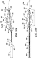
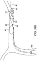
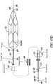
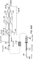
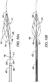
- the basket 54 has an open proximal end 60 and a substantially closed distal end 62, which is formed by distal tube 76.
- the distal and proximal hubs 74 and 76 and the distal basket 54 are comprised of a nitinol having the same material composition.
- the size of the mesh openings 58 decreases from the proximal end 60 of the basket 54 to the distal end 62.
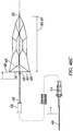
- the distal basket 54 is best seen in FIG. 2 and can be comprised of a different number of cell patterns.
- the distal basket 54 is not shown in FIGs. 3-10 for ease of illustrating the other components in the system 10.
- the method further includes attaching the pull wire 16 to the distal tube 76 so that the distal tube 76 is not slideable along the pull wire 16 but instead the distal tube 76 moves with the pull wire 16.
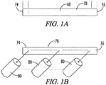
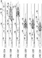
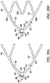
- Figures 11-29 illustrate an alternate embodiment 200 that includes one or more of the following additional features, as described below: twisting proximal strips/tethers 252, unattached/free distal-pointing crowns 258 that optionally curve inward and have x-ray markers 244, and enlarged openings/drop zones 262 in the basket 246 immediately distal to the unattached, distal-pointing crowns 258 that allow the obstruction or other object 270 to enter the distal basket interior 222.
- At least one of (and preferably all) the unattached, distal-pointing crowns 258A, 258B, 258C or 258D comprise an x-ray marker 244 that is more visible under x-ray as compared to the basket strips 291 when the distal body 216 is located in a cranial blood vessel 266 inside the body of a human and the x-ray is taken from outside the human's body.
- the x-ray marker 244 is a radiopaque material.
- radiopaque materials can include, but are not limited to, gold, platinum, palladium, tantalum, tungsten alloy, polymer material loaded with radiopaque filler, and the like.
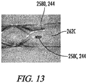
- the unattached, distal-pointing crowns 258 of the at least two cells 250 also each form part (namely a portion of the proximal boundary) of an enlarged cell 262 (which is the entry point of hard thrombus 270B into the basket interior 222) and further wherein the surface area of the enlarged cells 262 in the relaxed state is greater than the surface area of the other cells of the basket 246 in the relaxed state.
- the unattached, distal-pointing crowns 258 serve several functions: 1) they form flex points of the basket 246, which makes it easier for the system 200 to navigate the curves of the blood vessels 266 of the brains; 2) through the use of x-ray markers 244 on the unattached, distal-pointing crowns 258, they allow the operator to locate the enlarged cells 262 of the basket 246 that form the point at which hard thrombuses 270B enter the basket 246; and 3) they allow the operator to ratchet or force the object 270 into the basket 246 by moving the unattached, distal-pointing crowns 258 proximally and distally relative to the object 270.
- the x-ray marker 244 is a radiopaque material.
- radiopaque materials can include, but are not limited to, gold, platinum, palladium, tantalum, tungsten alloy, polymer material loaded with radiopaque filler, and the like.
- the basket strips 291 are comprised of nitinol and the x-ray marker 244 is comprised of a material having a density greater than the nitinol.
- the proximal and distal hubs/tube interiors 234 and 242 may comprise tantalum welded or otherwise attached to the interior 234 and 242 of the proximal and distal hubs/tubes 228 and 236.
- the proximal and the distal tubes 228 and 236 are generally cylindrical in shape and each has an outer diameter and an inner diameter, the inner diameter forming apertures of the proximal and distal tubes 228 and 236 and further wherein the outer diameters of the proximal and distal tubes 228 and 236 are substantially the same size and further wherein the inner diameters of the proximal and distal tubes 228 and 236 are substantially the same size.
- the mandrel 900 includes a generally cylindrical body 901 with tapered proximal and distal ends 902 and 903 that slope like the ends of a pencil.
- the cylindrical body 901 includes two grooves 904 that extend around the circumference of the cylindrical body 901.
- the grooves 904 include tapered portions 905 that slope towards the distal end 903, which are designed to shape the unattached distal-pointing crowns 258.
- the grooves 904 are generally in the shape of a truncated cone, as shown in FIGs. 63-64 ).
- the two proximal, unattached distal-pointing crowns 258A and 258B are located approximately the same distance from the proximal hub/tube 228 and are oriented approximately 180 degrees relative to each other.
- the two proximal enlarged openings/drop zones 262A and 262B distal to the proximal, unattached distal pointing crowns 258A and 258B are located approximately the same distance from the proximal hub/tube 228 and the centres of the two proximal enlarged openings/drop zones 262A and 262B are oriented approximately 180 degrees relative to each other.
- the proximal, unattached distal-pointing crowns 258A and 258B form part of the proximal boundary of the proximal, enlarged cells/drop zones 262A and 262B
- the distal, unattached distal-pointing crowns 258C and 258C form part of the proximal boundary of the distal, enlarged cells/drop zones 262C and 262D).
- the distal body 216 has four rows of x-ray markers namely, 1) a first row of one x-ray marker, which is located inside the proximal tube denominated by the numeral 228, 244; 2) a second row of two x-ray markers, which are located at the two proximal, unattached distal-pointing crowns (the two markers are oriented 180 degrees relative to each other) denominated by the numerals 258A, 244 and 258B, 244; 3) a third row of two x-ray markers, which are located at the two distal, unattached distal-pointing crowns (these two markers are oriented 180 degrees relative to each other and 90 degrees relative to the two proximal, unattached distal-pointing crowns) denominated by the numerals 258C, 244 and 258D, 244; and 4) a fourth row of one x-ray marker, which is located inside the distal tube denominated by the numeral 236, 24
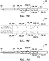
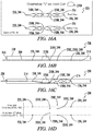
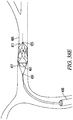
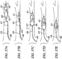
- FIGs. 15A-G illustrate stepwise use of the distal body 216 in retrieving a soft clot 270A in a human intracranial artery 266.
- the distal body 216 in FIGS. 15A-15G is in Orientation 1).
- the surgeon determines the location of the clot 270A in the vessel 266 using, for example, a contrast dye injected proximal and distal to the clot 270A.
- the delivery catheter 208 which is enveloping the distal body 216, is positioned in the blood vessel 266 so that the two proximal, unattached distal-pointing crowns 258A and 258B are immediately distal to the clot 270A. See FIG.
- the first vantage point shows four rows of x-ray markers.
- the first row is a single point, which represents the x-ray marker located in the proximal tube 228, 244; the proximal tube x-ray marker 228, 244 always appears as a single point.
- the second row is a single point, which represents the x-ray marker located at the front, proximal, unattached distal-pointing crown 258B, 244; the reason that this second row of markers is a single point is that the rear x-ray marker of the second row 258A, 244 is hidden from view because it is directly behind the front x-ray marker of the second row 258B, 244.
- the fourth row is a single point, which represents the x-ray marker located in the distal tube 236, 244; the distal tube x-ray marker 236, 244 always appears as a single point. Without moving the distal body 216, the surgeon then irradiates the four rows of x-ray markers from a second vantage point 90 degrees offset from the first vantage point (i.e., from the bottom of the distal body 216 in the orientation shown in FIG. 15A ). As shown, the first row is, as always, a single point, which represents the x-ray marker located in the proximal tube 228, 244.
- the surgeon concludes that the clot is a soft clot 270A that has entered into the distal body interior 222 and the surgeon removes the distal body 216 and the soft clot 270A, captured by the distal body 216, by moving the distal body 216 proximally out of the vessel 266, as shown in FIG. 15G .
- the distal body 216 is then deployed from the delivery catheter 208 by moving the catheter 208 proximally.
- the hard clot 270B which is located above the distal body 216, collapses the distal body 216, as shown in FIG. 16C .
- the surgeon is unaware that the clot 270B has collapsed the distal body 216.
- the surgeon irradiates the x-ray markers at a first vantage point (i.e., from the front of the distal body 216; i.e., into the page).
- the first vantage point shows four rows of x-ray markers.
- the first row is, as always, a single point, representing the x-ray marker located in the proximal tube - i.e., 228, 244.
- the second row is a single point, which represents the x-ray marker located at the front, proximal, unattached distal-pointing crown 258B, 244; the reason that this second row of markers is a single point is that the rear x-ray marker of the second row 258A, 244 is hidden from view because it is directly behind the front x-ray marker of the second row 258B, 244.
- the surgeon then irradiates the markers from a second vantage point 90 degrees offset from the first vantage point (i.e., from the bottom of the distal body 216).
- the first row is, as always, a single point, which represents the x-ray marker located in the proximal tube 228, 244.
- the second row has two points, which represents the two x-ray markers located at the proximal, unattached distal-pointing crowns 258A, 244 and 258B, 244; the reason that this second row of markers shows up as two points is that neither marker in the second row is hidden from view on the x-ray at this offset angle - rather, one marker 258B, 244 is located above the other marker 258A, 244 - and although the distal body 216 is collapsed at the proximal, unattached distal-pointing crowns as shown in FIG. 16C , the second row of x-ray markers have not converged because the clot 270B is on top of the second row of x-ray markers.
- the third row is a single point, which represents the x-ray marker located at the bottom, distal, unattached distal-pointing crown 258D, 244; the reason that this third row of markers is a single point is that the top x-ray marker of the third row 258C, 244 is directly behind the bottom x-ray marker of the third row 258D, 244, and thus, hidden from view.
- the fourth row is, as always, a single point, which represents the x-ray marker located in the distal tube 236, 244.
- the surgeon concludes that neither the second row 258A, 244 and 258B, 244 nor the third row 258C, 244 and 258D, 244 of x-ray markers (i.e., the x-ray markers at both the proximal and distal unattached distal pointing-crowns) has converged.
- the surgeon then moves the distal body 216 proximally so that the distal, unattached distal-pointing crowns 258C, 244 and 258D, 244 are immediately distal to the clot 270B and the surgeon then irradiates the x-markers again from the first vantage point.
- FIG. 16E the surgeon then moves the distal body 216 proximally so that the distal, unattached distal-pointing crowns 258C, 244 and 258D, 244 are immediately distal to the clot 270B and the surgeon then irradiates the x-markers again from the first vantage point.
- the first row is, as always, a single point, representing the x-ray marker located in the proximal tube 228, 244.
- the second row is a single point, which represents the x-ray marker located at the front, proximal, unattached distal-pointing crown 258B, 244; the reason that this second row of markers is a single point is that the rear x-ray marker of the second row 258A, 244 is hidden from view because it is directly behind the front x-ray marker of the second row 258B, 244.
- the first row is, as always, a single point, which represents the x-ray marker located in the proximal tube 228, 244.
- the second row has two points, which represents the two x-ray markers located at the proximal, unattached distal-pointing crown 258A, 244 and 258B, 244; the reason that this second row of markers shows up as two points is that neither marker in the second row is hidden from view on the x-ray at this offset angle and the distal body 216 is not collapsed at the proximal, unattached distal-pointing crowns 258A, 244 and 258B, 244.
- 16H shows that the distal, unattached distal-pointing crowns 258C, 244 and 258D, 244 are not converged, and, thus, the surgeon concludes that the hard clot 270B has entered the distal body interior 222. The surgeon then removes the distal body 216 and the hard clot 270B, captured by the distal body 216, by moving the distal body 216 proximally out of the vessel 266.
- the distal body 216 is then deployed from the catheter 208 by moving the catheter 208 proximally.
- the soft clot 270A which is unable to collapse the distal body 216, then enters the distal body interior 222. See FIG. 17C .
- the surgeon is unaware that the clot 270A has entered into the distal body interior 222.
- the surgeon irradiates the x-ray markers at a first vantage point (i.e., from the front of the distal body; into the page).
- the first vantage point shows four rows of x-ray markers.
- the third row has a single point, which represents the x-ray marker located at the front (in Orientation 2), distal, unattached distal-pointing crown 258C, 244; the reason that this third row of markers is a single point is that the rear (in Orientation 2) x-ray marker 258D, 244 of the third row is hidden from view because it is directly behind the front x-ray marker 258C, 244 of the third row.
- the fourth row is, as always, a single point, representing the x-ray marker located in the distal tube 236, 244.
- the surgeon then irradiates the markers from a second vantage point 90 degrees offset from the first vantage point (i.e., from the bottom of the distal body, as shown in this view).
- the first row is, as always, a single point, which represents the x-ray marker located in the proximal tube 228, 244.
- the third row has two points, which represents the two x-ray markers located at the distal, unattached distal-pointing crowns 258C, 244 and 258D, 244; the reason that this third row of markers shows up as two points is that neither marker in the third row is hidden from view on the x-ray at this offset angle and the distal body 216 is not collapsed at the distal, unattached distal-pointing crowns 258C, 244 and 258D, 244.
- the fourth row is, as always, a single point, which represents the x-ray marker located in the distal tube 236, 244.
- the results are the same as FIG. 17D .
- the surgeon concludes that neither the second row 258A, 244 and 258B, 244 nor the third row of x-ray markers 258C, 244 and 258D, 244 (i.e., the x-ray markers at both the proximal and distal unattached distal pointing-crowns) were converged at either the original position of the distal body 216 ( FIG. 17C and 17D ) or the position after moving the distal body 216 proximally ( FIG. 17E and 17F ), and, thus, the distal body 216 was expanded in the vessel 266 in both positions.
- the surgeon concludes that the clot 270A is a soft clot 270A that has entered into the distal body interior 222 and the surgeon removes the distal body 216 and the soft clot 270A, captured by the distal body 216, by moving the distal body 216 proximally out of the vessel 266, as shown in FIG. 17G .
- the clot 270B enters the distal body interior 222 in an enlarged cell/drop zone 262C immediately distal to one of the distal, unattached distal-pointing crowns 258C).
- the surgeon determines the location of the clot 270B in the vessel 266 using, for example, a contrast dye injected proximal and distal to the clot 270B.
- the delivery catheter 208 which is enveloping the distal body 216, is positioned in the blood vessel 266 so that the two proximal, unattached distal-pointing crowns 258A and 258B are immediately distal to the clot 270B. See FIG. 18B .
- the distal body 216 is then deployed from the catheter 208 by moving the catheter 208 proximally.
- the hard clot 270B which is located above the distal body 216, collapses the distal body 216, as shown in FIG. 18C .
- the surgeon is unaware that the clot 270B has collapsed the distal body 216.
- the surgeon irradiates the x-ray markers at a first vantage point (i.e., from the front of the distal body in Orientation 2; into the page).
- the first vantage point shows four rows of x-ray markers.
- the first row is, as always, a single point, representing the x-ray marker located in the proximal tube 228, 244.
- the second row has only one point because the clot 270B, which is on top of the second row of x-ray markers 258A, 244 and 258B, 244 (i.e., the markers at the proximal, unattached distal-pointing crowns), has pushed them together.
- the first row is, as always, a single point, which represents the x-ray marker located in the proximal tube 228, 244.
- the second row has a single point because the top (in Orientation 2) x-ray marker of the second row 258A, 244 is located behind the bottom (in Orientation 2) x-ray marker 258B, 244 and thus, the top x-ray marker of the second row 258A, 244 is hidden from view.
- the third row has two points, which represents the x-ray markers located at the distal, unattached distal-pointing crowns 258C, 244 and 258D, 244; in this x-ray view neither of the x-ray markers of the third row is hidden from view.
- the fourth row is, as always, a single point, which represents the x-ray marker located in the distal tube 236, 244.
- the surgeon concludes that the second row of x-ray markers 258A, 244 and 258B, 244 (i.e., the x-ray markers at the proximal, unattached distal pointing-crowns) has converged.
- the surgeon then moves the distal body 216 proximally so that the distal, unattached distal-pointing crowns 258C, 244 and 258D, 244 are immediately distal to the clot 270B.
- the clot 270B enters the distal body interior 222 immediately distal to the top (in Orientation 2), proximal unattached distal-pointing crown 258A and the distal body 216 is no longer collapsed. The surgeon then irradiates the x-markers again from the first vantage point. As shown in FIG. 18F , the first row is, as always, a single point, representing the x-ray marker located in the proximal tube 228, 244.
- the second row has two x-ray markers because the distal body 216 is not collapsed and neither the top (in Orientation 2) 258A, 244 nor the bottom 258B, 244 (in Orientation 2) x-ray marker of the second row (i.e., the marker at the proximal, unattached distal-pointing crowns) is hidden from view.
- the third row has only one point because the rear (in Orientation 2), distal unattached distal-pointing crown 258D, 244 is hidden behind the front (in Orientation 2), distal, unattached distal pointing-crown 258C, 244.
- the fourth row is, as always, a single point, representing the x-ray marker located in the distal tube 236, 244.
- the third row has two points because neither the front nor the rear x-ray markers at the distal, unattached, distal-pointing crowns 258C, 244 and 258D, 244 is hidden from view.
- the fourth row is, as always, a single point, which represents the x-ray marker located in the distal tube 236, 244. Based on the information from FIGs. 18D and 18F , the surgeon concludes that the clot 270B has entered into the distal body interior 222. The surgeon then removes the distal body 216 and the hard clot 270B, captured by the distal body 216, by moving the distal body 216 proximally out of the vessel 266, as shown in FIG. 18G . Upon comparing FIGs.
- the orientation of the enlarged cells/drop zone 262A-D relative to the orientation of a hard clot 270B determine which enlarged cell/drop zone 262A, 262B, 262C, or 262D, the hard clot 270 enters the distal body interior 222 through.
- the hard clot 270B is located above the distal body 216, and thus, the hard clot 270B must enter through the enlarged cell/drop zone located at the top of the distal body, which in the orientation of the distal body shown in FIGs.
- the hard clot 270B is again located above the distal body and, thus, the hard clot 270B must enter through the enlarged cell/drop zone located at the top of the distal body.
- the enlarged cell/drop zone located at the top of the distal body 216, in the orientation of the distal body 216 shown in FIGs. 18A-G is the enlarged cell/drop zone 262A immediately distal to the top, proximal, unattached, distal-pointing crown 258A.
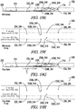
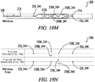
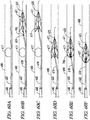
- FIGs. 19A-N illustrate stepwise use of the distal body 216 in retrieving a deformable cohesive, adherent clot 270C- i.e., a clot that is difficult to break up and is tightly adhered to the vessel wall 268 - in a human intracranial artery 266.
- the distal body 216 is in Orientation 2.
- the surgeon determines the location of the clot 270C in the vessel 266 using, for example, a contrast dye injected proximal and distal to the clot 270C.
- the delivery catheter 208 which is enveloping the distal body 216, is positioned in the blood vessel 266 so that the two proximal, unattached distal-pointing crowns 258A and 258B are immediately distal to the clot 270C. See FIG. 19B .
- the distal body 216 is then deployed from the catheter 208 by moving the catheter 208 proximally.
- the deformable, cohesive adherent clot 270C which is located above the distal body 216, collapses the distal body 216, as shown in FIG. 19C . However, at this time, the surgeon is unaware that the clot 270C has collapsed the distal body 216.
- the surgeon irradiates the x-ray markers at a first vantage point (i.e., from the front of the distal body; i.e., into the page).
- a first vantage point i.e., from the front of the distal body; i.e., into the page.
- the first vantage point shows four rows of x-ray markers.
- the first row is, as always, a single point, representing the x-ray marker located in the proximal tube 228, 244.
- the second row has a single point, corresponding to the top (in Orientation 2) and bottom (in Orientation 2), proximal, unattached distal-pointing crowns 258A, 244 and 258B, 244, which have converged because the clot 270C is collapsing the distal body 216.
- the third row has a single point, which represents the x-ray marker located at the front (in Orientation 2), distal, unattached distal-pointing crown 258C, 244; the x-ray marker located at the rear, distal, unattached distal-pointing crown 258D, 244 is hidden from view.
- the fourth row is, as always, a single point, representing the x-ray marker located in the distal tube 236, 244. Without moving the distal body 216, the surgeon then irradiates the markers from a second vantage point 90 degrees offset from the first vantage point (i.e., from the bottom of the distal body). As shown, the first row is, as always, a single point, which represents the x-ray marker located in the proximal tube 228, 244.
- the second row has a single point, which corresponds to the bottom (in Orientation 2), proximal, unattached distal-pointing crown 258B, 244; the top (in Orientation 2), proximal, unattached distal-pointing crown 258A, 244 is located behind the bottom, proximal, unattached distal-pointing crown 258B, 244 and hidden from view.
- the third row has two points, which correspond to the front (in Orientation 2) 258C, 244 and rear 258D, 244 (in Orientation 2), distal, unattached distal-pointing crowns, neither of which is blocked in this view.
- the fourth row is, as always, a single point, which represents the x-ray marker located in the distal tube 236, 244.
- the surgeon then moves the distal body 216 proximally (i.e., slightly withdraws the distal body 216).
- the surgeon then irradiates the x-markers again from the first and second vantage points.
- FIG. 19F the results are exactly the same as in FIG. 19D .
- the surgeon concludes that the clot 270C is a deformable cohesive, adherent clot 270C.
- the surgeon then oscillates the distal body 216 proximally and distally a small distance (e.g., about 1mm to about 2 mm) in the vessel 266, and the clot 270C begins to enter the distal body 216, as shown in FIG. 19G .
- the surgeon then irradiates the x-markers again from the first and second vantage points.
- the results are exactly the same as in FIG. 19D and FIG. 19F except that the second row of markers 258A, 244 and 258B, 244 (at the proximal, unattached distal-pointing crowns) are beginning to move apart.
- the surgeon then moves the distal body 216 proximally again, as shown in FIG. 19I .
- the surgeon then irradiates the x-markers again from the first and second vantage points.
- FIG. 19J the results are exactly the same as in FIGs. 19D and 19F , as the clot 270C has caused the second row of markers 258A, 244 and 258B, 244 to reconverge.
- the surgeon then irradiates the x-markers again from the first and second vantage points.
- the results show that the second row of markers 258A, 244 and 258B, 244 (at the proximal, unattached distal-pointing crowns) have moved apart.
- the surgeon concludes that the deformable cohesive, adherent clot 270C has been sufficiently captured by the distal body 216 and the surgeon then removes the distal body 216 and the clot 270C, captured by the distal body 216, by moving the distal body 216 proximally out of the vessel 266.
- distal body 216 has four enlarged cells/drop zones: one enlarged cells/drop zone at 0 degrees 262B, one enlarged cells/drop zone at 90 degrees 262C, one enlarged cells/drop zone at 180 degrees 262A and one enlarged cells/drop zone at 270 degrees 262D).
- an enlarged cell/drop zone 262A, 262B, 262C, or 262D is properly oriented to the clot 270B when the x-ray markers at the proximal, unattached distal-pointing crowns 258A, 244 and 258B, 244 or the distal, unattached distal pointing crowns 258C, 244 and 258D, 244 are together at both a first x-ray view and a second x-ray view 90 degrees relative to the first x-ray view, and the hard clot 270B can enter the enlarged cell/drop zone 262A, 262B, 262C, or 262D by moving the distal body 216 proximally. See FIG.
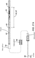
- the suction catheter 272 that is locked at between about 10 to about 60 cubic centimetres (cc).
- the suction catheter 272 has an outer diameter of between about 1.27 mm (0.05 inches) and about 2.3 mm (0.09 inches) and its outer diameter is substantially larger than the outer diameter of the delivery catheter 208.
- the clot 270 is located in the vessel 266 through the use of, for example, contrast dye injected proximal and distal to the clot 270.
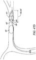
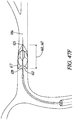
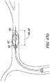
- a delivery catheter 208 containing the distal body 216 of FIGs. 20A, 20B and 20C is positioned in the tortuous vessel 266 distal to the clot 270. The delivery catheter 208 is withdrawn, deploying the distal body 216.
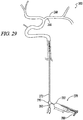
- the distal body 216 is moved proximally relative to the clot 270 and tension is exerted on pull wire 202. See FIG. 23 . While maintaining tension on the pull wire 202, a suction catheter 272 having a proximal end 274 and a distal end 276 is delivered over the pull wire 202 that is attached to the distal body 216. See FIG. 24 . (The reason for exerting tension on the pull wire 202 is that the pull wire 202 serves as the guide/track for the movement of the suction catheter 272 and without tension, the suction catheter 272 and pull wire 202 could end up in the ophthalmic artery 288).
- the distal end 276 of the suction catheter 272 is positioned against the clot 270.
- a syringe 278 is attached to the suction catheter 272 using a rotating haemostatic valve 290, which allows the surgeon to aspirate while a pull wire 202 is in the system.
- the surgeon aspirates the syringe 278 by pulling back on the lever 280 to a mark on the base 282 corresponding to between about 10 and about 60 cubic centimetres of fluid.
- the surgeon then locks the lever 280 (and attached plunger) into place, leaving the suction catheter 272 under suction.
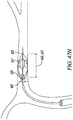
- the surgeon captures the clot 270 in the distal body 216 using the techniques described in FIGs. 15-19 .
- the distal body 216 and clot 270 become captured by the suction catheter 272. See FIGs. 27 and 28 .
- the surgeon then removes the suction catheter 272 and the distal body 216 and the clot 270, captured by the suction catheter 272, by moving the suction catheter 272 proximally out of the vessel 266. See FIG. 29 . It is believed that the suction catheter 272 would be helpful in the event that a small portion of the clot 270 breaks off when retrieving the clot 270 using the distal body 216.
- the systems 200 of FIGs. 11-20 were used to retrieve soft and hard clots 270A and 270B induced in a pig weighing between 30 to 50 kg.
- the weight of the pig was chosen so that the size of its vessels 266 would be approximate to the size of a human vessel.
- the pig was anesthetized.
- Several hard clots 270B were prepared by mixing pig blood and barium and incubating the mixture for 2 hours.
- Several soft clots 270A were prepared by mixing pig blood, thrombin and barium and incubating the mixture for 1 hour.
- the clots 270A and 270B were then inserted into a vessel 266 having a diameter of 2 to 4 mm. (Only one clot 270A and 270B was located in the vessel 266 at a time). Angiograms were then performed to confirm occlusion. After waiting ten minutes after confirming occlusion, the distal bodies 216 of FIGs. 11-20 were then delivered distal to the clots 270A and 270B as described above and were used to retrieve the clots 270A and 270B as described in FIGs. 11-19 . In each case, the distal bodies 216 were successful in retrieving the clots 270A and 270B.
- Figures 30-35 illustrate additional embodiments of object retrieval system.
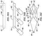
- the system 300 of FIGs. 30-35 includes:
- the distal basket 322 is comprised of a memory metal and has:
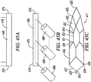
- each proximal crown 340 comprises a proximal tip 344 and further wherein each proximal strip 352 is configured to cover a proximal tip 344 when the distal basket 322 is in the distal collapsed state. See FIG. 35C , where the proximal strip 352 is folding back on itself to cover the proximal tip 344.
- each proximal crown 340 comprises an eyelet 370 and further wherein each proximal strip 352 passes through an eyelet 370.
- the distal end 356 of each proximal strip 352 comprises a loop 372 attaching the proximal strip 352 to an eyelet 370.
- each proximal crown 340 has an interior surface 348 facing the distal basket interior 324 and an exterior surface 350 opposite the interior surface 348 and further wherein each proximal strip 352 contacts an exterior surface 350 of a proximal crown 340 in the proximal collapsed state and the distal collapsed states, as best seen in FIGs. 35A-C .
- 35A-35C helps protect the proximal crowns 340 (in particular, the proximal tips 344 of the proximal crowns 340) from damaging the vessel wall 306 when the proximal crowns 340 move towards each other and the pull wire 308 when the distal basket 322 moves to the distal collapsed state and the proximal collapsed state.
- the pull wire 308 extends through the distal basket interior 324 and further wherein the proximal crowns 340 are configured to move towards each other and towards the pull wire 308 when the distal basket 322 moves from the gaping state to the distal collapsed state.
- the proximal crowns 340 are configured to remain a fixed distance from the distal end 328 of the distal basket 322 when the distal basket 322 moves from the relaxed state to the distal collapsed state. In other words, preferably, the distal basket length 330 does not change when the distal basket 322 moves from the distal basket relaxed state to the distal basket.
- the coaxial sheath 316 is a braided catheter comprised of a plurality of braids and further wherein the proximal segments of the braids are wound/woven together to form the braided catheter and further wherein an unwound/unwoven distal segment of each braid forms a proximal strip 352, as shown in FIG. 34 .
- At least one component of the system 300 (e.g., the proximal crown 340 or the distal tube 334) comprises an x-ray marker 374 that is more visible under x-ray as compared to the other components when the distal basket 322 is located in a cranial blood vessel 304 inside the body of a human and the x-ray is taken from outside the human's body.
- the x-ray marker 374 is a radiopaque material.
- radiopaque materials can include, but are not limited to, gold, platinum, palladium, tantalum, tungsten alloy, polymer material loaded with radiopaque filler, and the like.
- the non x-ray marker components are comprised of nitinol and the x-ray marker 374 is comprised of a material having a density greater than the nitinol.
- the proximal ends 354 of the proximal strips 352 are integral with the coaxial sheath 316. In other embodiments, as shown in FIG. 33 , the proximal ends 354 of the proximal strips 352 are attached to the coaxial sheath 316.
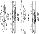
- the system 300 comprises between two and four proximal strips 352 and the proximal strips 352 are spaced substantially evenly apart (e.g., if there are two proximal strips 252, the strips are located about 180 degrees relative to each other, as shown in FIG. 30D ; if there are three proximal strips 252, the strips are located about 120 degrees relative to each other, as shown in FIG. 30C ; and if there are four proximal strips 252, the strips are located about 1200 degrees relative to each other, as shown in FIG. 30E ).
- the proximal strips 352 have a length 358 of from about 5 mm to about 40 mm in the relaxed state.
- the pull wire 308 extends through the basket interior 324 from the distal basket proximal end 326 to the distal basket distal end 328.
- the coaxial sheath interior has a size and shape, and further wherein the size and shape of the coaxial sheath interior are configured to prevent a segment 376 of the pull wire 308 located in the basket interior 322 and distal relative to the distal end 320 of the coaxial sheath 316 from moving through the coaxial sheath interior.
- the pull wire 308 has a stop 376 that consists of a knot or other enlargement.
- the system 300 is used in method of removing a clot 302 from a blood vessel 304 of an animal, the blood vessel 304 having an interior wall 306 forming the blood vessel 304, the method comprising the steps of:
- Figures 36-44 further illustrate other embodiments of a modular, easy-to-manufacture platform of systems for retrieving hard clots and other objects in animal lumens.
- the system includes a proximal tube, a distal tube, and a plurality of memory metal strips between the proximal and distal tubes.
- the plurality of memory metal strips form a wide range of basket designs.
- the proximal tube, memory metal strips, and distal tube are derived from a standard, off-the-shelf single tube of memory metal (e.g., nitinol), with the proximal tube and distal tube having the same inner diameter and outer diameter as the native tube from which they were derived and with the basket formed by cutting the middle portion of the native tube and expanding and shape-setting this cut portion.
- a standard, off-the-shelf single tube of memory metal e.g., nitinol
- the proximal tube and distal tube have an outer diameter that is from about 0.51 mm (0.02 inches) to about 0.76 mm (0.03 inches) (e.g., about 0.69 mm (0.027 inches)) so that the device fits inside a standard microcatheter and an inner diameter that is from about 0.25 mm (0.01 inches) to about 0.51 mm (0.02 inches).
- there are no welded parts between the proximal tube and distal tube which makes the system easy and cheap to reliably manufacture.
- the system also includes one or more catheters for deploying the system, and a first wire that is attached to the proximal tube and a second wire that is attached to the distal tube.
- the system includes two catheters - a guide catheter and a microcatheter.
- the plurality of memory metal strips attached to the proximal hub include a plurality of proximal tether memory metal strips, which have a proximal end attached to the distal end of the proximal tube.
- the present disclosure also provides a system for removing objects within an interior lumen of an animal.
- the system includes a pull wire having a proximal end, a distal end and a pull wire longitudinal axis extending from said proximal end to said distal end; a distal basket attached to said pull wire, said distal basket comprising a proximal end, a distal end, a distal basket length extending from said distal basket proximal end to said distal end, a distal basket height perpendicular to said distal basket length and said pull wire longitudinal axis, a proximal tube located at said proximal end of the distal basket, said proximal tube comprising a hollow interior, a plurality of proximal tether memory metal strips, a row of proximal cells defined by a plurality of proximal cell memory metal strips, each proximal cell comprising a proximal crown located at the proximal end of the proximal
- said proximal tether memory metal strips rotate about said pull wire longitudinal axis such that a distal end of a proximal tether memory metal strip is located between about 90 and about 270 degrees relative to said proximal end of the same proximal tether memory metal strip.
- said proximal tether memory metal strips and said proximal cell memory metal strips each have a thickness and further wherein said thickness of said proximal tether memory metal strips is between about 100 to about 175 percent of the thickness of the proximal cell memory metal strips.
- the length of said proximal tether memory metal strips is about 10 mm to about 20 mm in the relaxed state (and the length of the remainder of the basket is about 10 to about 20 mm in the relaxed state so that the total basket length is between about 20 to about 40 mm in the relaxed state).
- said distal end of said pull wire is attached to said proximal tube.
- Some or all of the proximal crowns of said proximal cells may be attached to a proximal tether memory metal strip.
- said distal basket further comprises a row of strut memory metal strips, each strut memory metal strip having a proximal end attached to a distal crown of a proximal cell and a distal end attached to a proximal crown of a distal cell.
- the distal basket comprises between two and four proximal tether memory metal strips.
- said proximal tether memory metal strips are integral with said proximal tube.
- said distal body further comprises a lead wire extending distally from said distal tube.
- said distal tube, said proximal tube, and said basket are comprised of a nitinol having the same material composition.
- said distal body further comprises an x-ray marker.
- said proximal and said distal tubes are generally cylindrical in shape and each has an outer diameter and an inner diameter, the inner diameter forming the apertures of the proximal and distal tubes and further wherein the outer diameters of the proximal and distal tubes are substantially the same size and further wherein the inner diameters of the proximal and distal tubes are substantially the same size.
- the outer diameters of the proximal and distal tubes are from about 0.28 mm (0.011 inches) to about 1.37 mm (0.054 inches), and further wherein the inner diameters of the proximal and distal tubes are from about 0.20 mm (0.008 inches) to about 1.30 mm (0.051 inches).
- the pull wire is generally cylindrical and further wherein the diameter of the pull wire is between about 0.20 mm (0.008 inches) and about 1.30 mm (0.051 inches).
- the first height is between about 2 millimetres and about 8 millimetres.
- the present disclosure also provides a method of removing an object from an interior lumen of an animal, said lumen having an interior wall forming said lumen, the method comprising the steps of:
- said interior lumen is an intracranial artery and said obstruction is a blood clot.
- the system includes:
- said tether memory metal strips rotate about said pull wire longitudinal axis such that a distal end of a tether memory metal strip is located between about 90 and about 270 degrees relative to said proximal end of the same proximal tether memory metal strip.
- the present disclosure provides a deployable system, generally designated by the numeral 410, for removing an obstruction such as a blood clot 417 or other object from a blood vessel 488 or other interior lumen of an animal.
- an obstruction such as a blood clot 417 or other object from a blood vessel 488 or other interior lumen of an animal.
- the obstruction may be, for example, extruded coils during aneurysm treatment, intravascular embolic material such as onyx or other obstructions requiring mechanical intravascular removal from small distal vessels.
- the drawings not all reference numbers are included in each drawing for the sake of clarity.
- FIGs. 37A-37B , 38A-E and 39A One example of a deployable basket system 410 is shown in FIGs. 37A-37B , 38A-E and 39A .
- the system 410 includes a pull wire 443 having a proximal end 445, a distal end 444 and a pull wire longitudinal axis 446 extending from said proximal end 445 to said distal end 444.
- the diameter of the pull wire 443 is between about 0.20 mm (0.008 inches) and about 1.30 mm (0.051 inches).
- the system 410 further includes a distal basket 411 attached to said pull wire 443, said distal basket 411 comprising a proximal end 469, a distal end 465, a distal basket length 467 extending from said distal basket proximal end 469 to said distal end 465, a distal basket height 461 perpendicular to said distal basket length 467 and said pull wire longitudinal axis 446, a proximal hub 439 located at said proximal end 469 of the distal basket 411 and comprising a hollow interior 441, said distal end 444 of said pull wire 443 attached to said proximal hub 439, a plurality of proximal tether memory metal strips 457, a plurality of proximal cells 436 defined by a plurality of proximal cell memory metal strips 466, each proximal cell 436 comprising a proximal crown 438 located at the proximal end of the proximal cell 436 and pointing generally in
- the proximal hub 439 and distal hub 425 are hollow tubes formed from the same tube of memory metal, as described below.
- the basket 411 includes a first row of two crowns (i.e., the proximal crowns 438 of the proximal cells 436) and then subsequent repeating rows of twice as many crowns as compared to the number of proximal crowns 438 (i.e., four crowns) along the basket length 467.
- the basket 410 further comprises a row 447 of distal cells 422 located distal to said proximal cells 436 and connected to said distal crowns 424 of said proximal cells 436, each distal cell 422 defined by a plurality of memory metal strips 466 and comprising a proximal crown 437 located at a proximal end of the cell 422 and pointing in the proximal direction and a distal crown 423 located at a distal end of the cell 422 and pointing in the distal direction, and further wherein the number of distal cells 422 is twice the number of proximal cells 436.
- the system further includes a coaxial tube, said coaxial tube configured to be received in said catheter, said coaxial tube having a proximal end, a distal end attached to said proximal hub, and a hollow interior, said pull wire passing through said coaxial tube hollow interior, said coaxial tube slideable along at least a segment of said pull wire.
- said proximal tether memory metal strips and said proximal cell memory metal strips each have a thickness and further wherein said thickness of said proximal tether memory metal strips is between about 25 to about 75 percent of the thickness of the proximal cell memory metal strips.
- the proximal tether memory metal strips are as thick or thicker than the memory metal strips forming the proximal cells and in such embodiments, the length of the proximal tether memory metal strips may be between about 10 mm and about 20 mm in the relaxed state.
- proximal tether memory metal strips rotate about said pull wire longitudinal axis such that a distal end of a proximal tether memory metal strip is located between about 90 and about 270 degrees relative to said proximal end of the same proximal tether memory metal strip.
- the distal basket further comprises a distal collapsed state in which said coaxial tube is located distal to said proximal crowns and wherein said distal basket, as measured at the proximal-most crown, has a third height, said third height less than said first height, wherein said catheter is configured to envelope said distal basket when said distal basket is in said distal collapsed state, and further wherein said distal basket is configured to move from said relaxed state to said distal collapsed state by moving said coaxial tube distally relative to said distal hub.
- said cord is comprised of a material selected from the group consisting of plastic, rubber, nylon, suture material, and braided catheter material.
- said cords are integral with said coaxial sheath.
- said cords are glued to said coaxial sheath.
- said cords are shrink wrapped to said coaxial sheath.
- said cords have a thickness of about 0.025 mm to about 2.5 mm (about 0.001 to about 0.1 inches) (more preferably, from about 0.1 mm to 0.46 mm (about 0.004 to 0.018 inches)) and have a length of from about 3 mm to about 20 mm in said relaxed state.
- said pull wire extends from said distal basket proximal end to said distal basket distal end and said pull wire is attached to said distal hub.
- all proximal crowns of said proximal cells are attached to a cord.
- said distal hub is generally cylindrical in shape and has an outer diameter and an inner diameter, the inner diameter forming the aperture of the distal hub and further wherein the outer diameter of the distal hub from about 0.28 mm (0.011 inches) to about 1.37 mm (0.054 inches), and further wherein the inner diameter of the distal hub is from about 0.20 mm (0.008 inches) to about 1.30 mm (0.051 inches).
- the distal tube has an outer diameter that is from about 0.51 mm (0.02 inches) to about 0.76 mm (0.03 inches) and an inner diameter that is from about 0.25 mm (0.01 inches) to about 0.51 mm (0.02 inches).
- the system includes a pull wire having a proximal end, a distal end and a pull wire longitudinal axis extending from said proximal end to said distal end; a coaxial tube having a proximal end, a distal end and a hollow interior, said pull wire passing through said coaxial tube hollow interior, said coaxial tube slideable along at least a segment of said pull wire; a distal basket attached to said pull wire and said coaxial tube, said distal basket comprising a proximal end, a distal end, a distal basket length extending from said distal basket proximal end to said distal end, a distal basket height perpendicular to said distal basket length and said pull wire longitudinal axis, a plurality of proximal tether memory metal strips, a plurality of cords, a plurality of proximal cells defined by a plurality of proximal cell memory metal strips, each proximal
- said cords have a thickness of from about 0.1 mm to about 0.25 mm (about 0.004 to about 0.1 inches) (more preferably about 0.1 mm to about 0.46 mm (about 0.004 inches to about 0.018 inches)) and further wherein said cords have a length of from about 3 mm to about 20 mm in said relaxed state.
- said pull wire extends from said distal basket proximal end to said distal basket distal end and said pull wire is attached to said distal hub.
- all proximal crowns of said proximal cells are attached to a cord.
- the distal basket comprises between two and four cords.
- said distal hub is attached to said pull wire such that said distal hub is not slideable along said pull wire.
- said distal basket further comprises a lead wire extending distally from said distal hub.
- said distal hub and said basket are comprised of a nitinol having the same material composition.
- said distal basket and/or said coaxial tube further comprises an x-ray marker that is more visible under x-ray as compared to the other components when the distal basket is located in a cranial blood vessel inside the body of a human and the x-ray is taken from outside the human's body.
- the x-ray marker is a radiopaque material.
- said distal hub is generally cylindrical in shape and has an outer diameter and an inner diameter, the inner diameter forming the aperture of the distal hub and further wherein the outer diameter of the distal hub is from about 0.28 mm (0.011 inches) to about 1.37 mm (0.054 inches), and further wherein the inner diameter of the distal hub is from about 0.20 mm (0.008 inches to about 1.30 mm (0.051 inches).
- the distal tube has an outer diameter that is from about 0.51 mm (0.02 inches) to about 0.76 mm (0.03 inches) and an inner diameter that is from about 0.25 mm (0.01 inches) to about 0.51 mm (0.02 inches).
- said interior lumen is an intracranial artery and said obstruction is a blood clot.
- the present disclosure provides a deployable system, generally designated by the numeral 610, for removing an obstruction such as a blood clot 617 or other object from a blood vessel 688 or other interior lumen of an animal.
- an obstruction such as a blood clot 617 or other object from a blood vessel 688 or other interior lumen of an animal.
- the obstruction may be, for example, extruded coils during aneurysm treatment, intravascular embolic material such as onyx or other obstructions requiring mechanical intravascular removal from small distal vessels.
- the drawings not all reference numbers are included in each drawing for the sake of clarity.
- the system 610 further includes a distal basket 611 attached to said pull wire 643, said distal basket 611 comprising a proximal end 669, a distal end 665, a distal basket length 667 extending from said distal basket proximal end 669 to said distal end 665, a distal basket height 661 perpendicular to said distal basket length 667 and said pull wire longitudinal axis 646, a proximal hub 639 located at said proximal end 669 of the distal basket 611, said proximal hub 639 comprising a hollow interior 641, said pull wire 643 passing through said proximal hub hollow interior 641, said proximal hub 639 slideable along at least a segment of the pull wire 643, a plurality of proximal tether memory metal strips 657, a plurality of proximal cells 636 defined by a plurality of proximal cell memory metal strips 666, each proximal cell 636 comprising a proximal crown 6
- the system further includes a guide catheter 630 and a microcatheter 632, which is wider and shorter than the guide catheter 630, so that the microcatheter 632 can fit inside the guide catheter 630.
- the microcatheter 632 has a hollow interior 615, a proximal end 616 leading to said interior 615 and a distal end 614 leading to said interior 615.
- the microcatheter 632 is comprised of a biocompatible material.
- guide catheter As used herein, the terms "guide catheter”, “microcatheter” and “catheter” generally refers to any suitable tube through which the system 610 can be deployed.
- the system 610 may utilize a plurality of catheters as described above, such as, for example, a wider catheter that travels to the brain and a very flexible, smaller diameter microcatheter that is delivered from the first catheter and travels through the small arteries of the brain.
- FIG. 46A shows the distal basket 611 collapsed inside a microcatheter 632.
- the distal basket 611 is in what's referred to as the proximal collapsed state. In this state, the system 610 is able to be located inside the microcatheter 632 and the basket height 661 is collapsed.
- the basket height 661 generally refers to the height at a particular location (e.g., at the proximal-most crown 638 of the distal basket 611 or the distal-most crown 623 of the proximal basket 633), it being understood that the height of the distal basket 611 and proximal basket 633 may vary along the distal basket length 667 and the length of the proximal basket 633.
- the proximal hub 639 is located a maximum distance from the distal hub 625.
- the distance from the proximal hub 639 to the distal hub 625 changes by exerting force on the proximal hub 639, as described herein, and the distance is shown in the drawings using the numeral 663. This distance is also generally equal to the length of the basket 667, as shown.
- FIG. 46B shows the same basket system as FIG. 46A , except that the basket 611 has been deployed from the distal end 614 of the microcatheter 632 by pulling the microcatheter 632 proximally.
- the basket 611 is now in a relaxed state and the basket height 661 has increased.
- the proximal tube 639 is located a short distance 629 proximal to the proximal-most crown 638.
- the basket length 667 and the distance 663 between the proximal and distal hubs 639 and 625 has decreased as the basket 611 has relaxed.
- the proximal stop 664 is merely an enlargement or x-ray marker 658 in the pull wire 643 that is taller and/or wider than the open coaxial tube interior 620 (i.e., the inner diameter of the coaxial tube 618).
- the pull wire 643 may be etched to provide guidance to the surgeon on the distance to push and pull the coaxial tube 618.
- FIG. 46C exemplifies what is referred to as the gaping state of the basket 611.
- a user merely pushes the proximal hub 639 distally towards the stationary distal hub 625. This causes the proximal tether memory metal strips 657 to increase the height 661 of the distal basket 611 at the proximal-most crown 638.
- the proximal tether memory metal strips 657 of the embodiment shown in FIGs. 46 , 47 and 50 are relatively short.
- the proximal tether memory metal strips 657 are relatively thin compared to the memory metal strips 666 that make up the proximal cells 636, which makes the proximal tether memory metal strips 657 easy to bend.
- the proximal memory metal strips 657 are substantially perpendicular (e.g., about 75 to about 105 degrees) relative to the longitudinal axis of the pull wire 646.
- FIG. 46D exemplifies what is referred to as the distal collapsed state.
- a user merely pushes the proximal hub 639 distally towards the stationary distal hub 625.
- This causes the proximal tether memory metal strips 657 to reduce the height 661 of the distal basket at the proximal-most crown 638, which in certain embodiments, allows the user to recapture the system 610 in the microcatheter 632. This is particularly helpful if the system 610 was deployed at the wrong location.
- the pull wire 643 includes a distal stop 660, which prevents the proximal hub 39 from moving too far distally and breaking.
- FIG. 46E also exemplifies the proximal collapsed state.
- a user merely pulls the proximal hub 639 away from the stationary distal hub 625.
- This causes the proximal tether memory metal strips 657 to reduce the height 661 of the distal basket at the proximal-most crown 638, which in certain embodiments, allows the user to recapture the system 610 in the microcatheter 632. This is particularly helpful if the system 610 was deployed at the wrong location.
- the pull wire 643 includes a middle stop 655, which prevents the proximal hub 639 from moving too far proximally.
- the basket 611 is moved closer to the clot 617 by a user pulling the pull wire 643 and coaxial tube 618 proximally at the same time. Then, as shown in FIG. 47E , the user uses the coaxial tube 618 to move the proximal hub 639 toward the distal hub 625 so that the basket 611 is in the gaping state.
- the gaping state is particularly important, as it believed to allow the basket 611 to capture the clot 617 without having the clot 617 collapse the basket 611.
- FIG. 47F the basket 611 is moved proximally over the clot 617. Then, as shown in FIG.
- the coaxial tube 618 is moved further proximally to close the proximal end 669 around the clot 617.
- the system 611 is moved proximally by moving the pull wire 643 and the coaxial tube 618 proximally simultaneously.
- FIG. 50A shows a close-up view of the proximal end of the basket 611, including the proximal tube interior 641, the attachment of the proximal tether memory metal strips 657 at the distal end 655 of the proximal hub 639, and the proximal crowns 638 of the proximal cells 636.
- all proximal crowns 638 of the proximal cells 636 are attached to a proximal tether memory metal strip 657.
- FIG. 56 illustrates a side, perspective view of a basket system 610 with relatively thick and short proximal tether memory metal strips 657 (i.e., the proximal tether memory metal strips 657 are slightly thicker than the memory metal strips 666 making up the proximal cells 636.
- the proximal tether memory metal strips 657 are thicker than the memory metal strips 666 forming the proximal cells 636 of the distal basket 611.
- the proximal tether memory metal strips 657 resist deforming when the proximal hub 635 is translated distally toward the stationary distal hub 629 and instead the proximal tether memory metal strips 657 are bowed out laterally, dissecting through or around the clot 617 and centering, buttressing and strengthening the opening of the basket 611.
- the basket 611 is deployed distal to the clot 617.
- the basket 611 is move distally so that the clot 617 partially collapses the proximal tether memory metal strips 657. See FIG. 57B .
- the proximal hub 614C is moved distally to slice the proximal tether memory metal strips 657 through the clot 617. See FIG. 57C .
- the basket 611 is moved proximally to ensnare the clot 617. See FIG.57 .
- the tether proximal memory metal strips 657 are partially withdrawn into the microcatheter 632 and the system is removed from the body. See FIG. 57E .
- FIG. 51 illustrates a similar to basket system 610 to FIGs. 46 , 47 and 50 .
- the proximal tether memory metal strips 657 are relatively thin and short and the proximal memory metal strips making up the remainder of the basket are thickest at the proximal-most crown 38 and decrease gradually along the distal basket length 667.
- FIG. 52 illustrates a similar to basket system 610 to FIGs. 46 , 47 , 50 , and 51 .
- the proximal tether memory metal strips 657 are relatively thin and short.
- the length 654A of the first proximal memory metal strip 657A and the length 654B of the second proximal memory metal strip 657B are equal to the height 661 of the basket 611 in the relaxed state, as measured at the proximal-most crown 638, plus or minus two mm.
- the height of the vessel 688 is 4 mm and the length of the proximal tether memory metal strips is 3 mm
- the height 661 of the basket 611 as measured at the proximal-most crown 638 could be 4 mm. This is believed to allow the basket 611 in the gaping state to fill the vessel 688.
- FIG. 48 illustrates another embodiment of the basket system 610.
- the pull wire 643 does not extend through the entire basket 611 but rather ends at distal stop 660.
- the proximal tether memory metal strips 657 of the embodiment of FIG. 48 are about the same thickness as the thickness 656 of the proximal cell memory metal strips 666, which makes the basket 611 relatively rigid and the proximal tether memory metal strips 657 relatively inflexible, which may be desired for certain applications.
- moving the basket 611 from the relaxed state (see FIG. 48A ) to the gaping state by moving the coaxial tube 618 proximally does not greatly enhance the basket height 661 in this embodiment due to the rigidity.
- FIGs. 49A-49C illustrate stepwise deployment and use of a basket system 610 with three relatively thin and short proximal tether memory metal strips 657; the system 610 is deployed in a blood vessel 688 to retrieve a clot 617.
- the length 654A of the first proximal tether memory metal strip 657A also may be two times the height 661 of the basket 611, as measured at the proximal-most crown 638 plus or minus 2 mm and the length 654B of the second proximal tether memory metal strip 657B may be two times the height 661 of the basket 611 plus or minus 2mm.
- the vessel 688 has a height of 4 mm and the length 654A and 654B of the proximal tether memory metal strips 657A and 657B are 7 mm each
- the height 661 of the distal basket 611 as measured at the proximal-most crown may be set to for example 4 mm in the relaxed state.
- the proximal end of the system 610 is shown at the bottom end of FIGs. 45-62 and the distal end of the system 610 is shown at the top end of FIGs. 45-62 because a principal use of the system 610 is to remove a blood clot 617 from a human intracranial artery 688, in which case the system 610 generally will enter the artery 688 at its proximal end by the surgeon entering the patient's body near the groin and pushing the catheter 632 towards the brain.
- the diameter of human arteries 688 generally decrease from their proximal end to their distal end.
- the distal basket 611 may be located proximally relative to the catheter 632 as the term proximally and distally are used in that lumen.
- FIG. 54 illustrates another embodiment of a basket system 611.
- the system 611 includes a proximal hub 639 that is slideable towards a distal hub 625 (similar to the prior embodiments). The difference is that the tether memory metal strips 657 actually join the proximal basket 633 and the distal basket 611.
- the proximal basket 633 is comprised of a plurality of proximal cells 636 attached to the proximal hub 639 and a plurality of distal cells 622 and the distal basket is comprised of a plurality of proximal cells 636 attached to the proximal hub 639 and a plurality of distal cells 622 and the tether memory metal strips 657 join a distal crown 623 of a distal cell 622 of the distal basket 611 with a proximal crown 638 of a proximal cell 636 of the proximal basket 633.
- FIG. 54B movement of the proximal hub 639 toward the distal hub 625 increases the height 634 of the proximal basket 633 as measured at the distal-most crown 623 of the distal basket 611.
- FIG. 55A and 55B illustrate an embodiment of the proximal tether memory metal strips 657 rotating about said pull wire longitudinal axis 646 such that the distal end 653 of a proximal tether memory metal strip 657 is located between about 90 and about 270 degrees relative to said proximal end 655 of the same proximal tether memory metal strip 657.
- proximal tether memory metal strips 657 may rotate around their longitudinal axis 654 such that a distal end 653 of a proximal tether memory metal strip 657 rotates about 90 and about 270 degrees around this tether longitudinal axis 654 from the distal end 653 to the proximal end 655 of the same proximal memory metal strip 657.
- 55C illustrates an exemplary embodiment, where the proximal end 655A of the first proximal tether memory metal strip 657A is located attached to the proximal tube 639 at the 12 o'clock position and the distal end 653A of the same proximal tether memory metal strip 657A is attached to a proximal-most crown 639 at the 9 o'clock position.
- the second proximal tether memory metal strip 657B is located attached to the proximal tube 639 at the 6 o'clock position and the distal end 653B of the same proximal tether memory metal strip 657b is attached to the other proximal-most crown 639 at the 3 o'clock position.
- FIG. 55D and 55E illustrate a similar embodiment with the proximal tether memory metal strips 657A and 657B rotating 180 degrees.
- FIG. 55D illustrates an exemplary embodiment, where the proximal end 655A of the first proximal tether memory metal strip 657A is located attached to the proximal tube 639 at the 12 o'clock position and the distal end 653A of the same proximal tether memory metal strip 657A is attached to a proximal-most crown 639 at the 6 o'clock position.
- the second proximal tether memory metal strip 657B is located attached to the proximal tube 639 at the 6 o'clock position and the distal end 653B of the same proximal tether memory metal strip 657b is attached to the other proximal-most crown 639 at the 12 o'clock position.
- the basket system 610 is prepared by a process that includes one or more of the following steps, as illustrated in FIG. 45 :
- steps h) and i) above replaced with the steps of inserting a pull wire comprising a proximal end, a distal end, a stop located adjacent to said distal end, through said proximal tube interior, said stop having a width and/or height that is greater than said proximal tube interior, said stop located distal relative to said proximal tube interior, so that said proximal tube is slideable distally until the proximal hub reaches said stop, said pull wire not contacting said distal tube; and attaching a leader wire to said distal tube.
- the middle portion 678 is expanded by heating the mandrel and the middle portion 678 by, for example, placing the mandrel and the middle portion 678 in a fluidized sand bath at about 500°C for about 3 to about 7 minutes. As the middle portion 678 is heated, the heating causes the crystalline structure of the memory metal tube 668 to realign.
- the mandrel is tapered (e.g., substantially conical or bullet in shape) so that the portion of the distal basket 611 formed from the middle portion 678 tapers from the proximal-most crown 638 to the distal end 666.
- the proximal and distal ends of the tube 674 and 676 are not shape set by the mandrel and are not cut by the laser 680 so that the proximal and distal ends 674 and 676 do not change in shape and only slightly expand in size under heating and return to the size of the native tube 668 after the heat is removed.
- the laser cuts are programmed via a computer.
- the laser 680 is preferably focused between the inner and outer diameter of the desired cutting surface and a coolant is passed through the memory metal tube 668 so that the laser 680 cools before reaching the surface directly opposite the desired cutting surface.
- the portions of the wall not cut by the laser 680 create the proximal and distal tubes 674 and 676 as well as the other components of the distal basket 611, and memory metal strips 657 and 666, as described.
- the memory metal selected for the native tube 668 has a heat of transformation below average human body temperature (37°C) so that the distal basket 611 has sufficient spring and flexibility after deployment from the catheter 632 in the human blood vessel 688.
- the native tube 668 (and hence the distal and proximal tubes 674 and 676) have an outer diameter of less than about 1.33 mm (4 French), e.g., a diameter of about 0.33 mm to about 1.33 mm (about 1 to about 4 French).
- the diameter of the pull wire 643 is between about 0.20 mm (0.008 inches) and about 1.30 mm (0.051 inches), as noted above, and in such embodiments, the diameter of the pull wire 43 may be approximately equal to the inner diameter 672 of the native nitinol tube 668.
- distal basket 611 from a single memory metal tube 668 provides ease of manufacturing and safety from mechanical failure and provides tensile strength necessary for the system 610 to remove hard thrombus 617 and other obstructions.
- the method further includes providing a coaxial tube 618, said coaxial tube 618 comprising a hollow interior 620 receiving said pull wire 643, a proximal end 621, and a distal end 619, and attaching said distal end 619 of said coaxial tube 643 to said proximal tube 625.
- the method of attaching said distal end 619 of said coaxial tube 618 to said proximal tube 625 comprises welding said distal end 619 of said coaxial tube 618 to said proximal tube 625.
- the method of attaching said distal end 619 of said coaxial tube 618 to said proximal tube 625 comprises shrink wrapping said distal end 619 of said coaxial tube 618 to said proximal tube 625. In other embodiments, the method of attaching said distal end 619 of said coaxial tube 618 to said proximal tube 625 comprises gluing said distal end 619 of said coaxial tube 618 to said proximal tube 625.
- the basket 611 further comprises a row 648 of proximal cells 636, each proximal cell 636 defined by a plurality of memory metal strips 666 and comprising a proximal crown 638 located at a proximal end of the cell 636 and pointing in the proximal direction and a distal crown 624 located at a distal end of the cell and pointing in the distal direction and further wherein each of said proximal crowns 638 of said proximal cells 636 is attached to a distal end 653 of a proximal tether memory metal strip 657.
- the basket 610 further comprises a row 647 of distal cells 622 located distal to said proximal cells 636 and connected to said distal crowns 624 of said proximal cells 636, each distal cell 622 defined by a plurality of memory metal strips 666 and comprising a proximal crown 637 located at a proximal end of the cell 622 and pointing in the proximal direction and a distal crown 623 located at a distal end of the cell 622 and pointing in the distal direction, and further wherein the number of distal cells 622 is twice the number of proximal cells 636.
- the basket system 610 further comprises a row 649 of strut memory metal strips 652, each strut memory metal strip 652 having a proximal end 651 attached to a distal crown 624 of a proximal cell 636 and a distal end 650 attached to a proximal crown 637 of a distal cell 622.
- the basket 611 comprises no welded components and said proximal tether memory metal strips 657 are integral with said proximal cell crowns 638.
- the basket system 611 comprises between two and four proximal tether memory metal strips 657.
- the memory metal tube 668 prior to cutting the memory metal tube 668, has an outer diameter 686 that is from about 0.28 mm (0.011 inches) to about 1.37 mm (0.054 inches) and an inner diameter 684 that is from about 0.20 mm (0.008 inches) to about 1.30 mm (0.051 inches).
- the proximal tube 639 and distal tube 625 have an outer diameter that is from about 0.51 mm (0.02 inches) to about 0.76 mm (0.03 inches) and an inner diameter that is from about 0.25 mm (0.01 inches) to about 0.51 mm (0.02 inches).
- the method further includes placing said basket 611 inside a catheter 632 comprised of a biocompatible material.
- the method further includes the steps of placing the basket 611 inside a lumen 688 of an animal and using the basket to retrieve an object 617 located inside said lumen 688.
- the basket system 610 does not include a proximal hub 639 and the system 610 includes a plurality of cords 703 (e.g., 2-4 cords 703) instead of or in addition to said proximal tether memory metal strips 657.
- FIG. 15-17 shows a first set of embodiments, where soft cords made of rubber, nylon, suture material, braided catheter material, platinum coils, and ultrathin nitinol for example, are used.
- the cords 703 have a proximal end 704 attached to the distal end 619 of the coaxial tube 618 and a distal end 705 attached to a proximal crown 638 of a proximal cell 636.
- FIG. 58 illustrates one embodiment in which the cords 703 are relatively long.
- FIG. 59 illustrates another embodiment in which the cords 703 are relatively short.
- the system 610 is used in a method that includes
- steps g)-h) above are replaced with the steps below:
- an advantage of this embodiment is that the cords 703 move distally to the proximal-most crowns 638 so they do not obstruct entry way of the clot 617 into the distal basket 611.
- the system 610 includes cords 703 and proximal tether memory metal strips 657.
- the proximal tether memory metal strips 657 have a proximal end 655 attached to the distal end 619 of the coaxial tube 618.
- the cords have a proximal end attached to the distal end 653 of the proximal memory metal strips 657 and a distal end attached to a proximal crown 638 of a proximal cell 636.
- the system 610 is used in a method of removing an object from an interior lumen 688 of an animal, said lumen 688 having an interior wall forming said lumen 688 that includes:
Landscapes
- Health & Medical Sciences (AREA)
- Life Sciences & Earth Sciences (AREA)
- Surgery (AREA)
- Veterinary Medicine (AREA)
- Public Health (AREA)
- General Health & Medical Sciences (AREA)
- Animal Behavior & Ethology (AREA)
- Heart & Thoracic Surgery (AREA)
- Engineering & Computer Science (AREA)
- Molecular Biology (AREA)
- Biomedical Technology (AREA)
- Nuclear Medicine, Radiotherapy & Molecular Imaging (AREA)
- Medical Informatics (AREA)
- Vascular Medicine (AREA)
- Orthopedic Medicine & Surgery (AREA)
- Surgical Instruments (AREA)
- Chemical & Material Sciences (AREA)
- Epidemiology (AREA)
- Birds (AREA)
- Zoology (AREA)
- Wood Science & Technology (AREA)
- Inorganic Chemistry (AREA)
- Animal Husbandry (AREA)
- Chemical Kinetics & Catalysis (AREA)
- Prostheses (AREA)
Priority Applications (2)
| Application Number | Priority Date | Filing Date | Title |
|---|---|---|---|
| EP24214650.4A EP4520290A3 (fr) | 2014-05-18 | 2015-05-18 | Système de récupération de caillot |
| EP22182531.8A EP4098215B1 (fr) | 2014-05-18 | 2015-05-18 | Système de récupération de caillot |
Applications Claiming Priority (8)
| Application Number | Priority Date | Filing Date | Title |
|---|---|---|---|
| US201461994919P | 2014-05-18 | 2014-05-18 | |
| US201461994934P | 2014-05-18 | 2014-05-18 | |
| US14/558,712 US9155552B2 (en) | 2014-01-03 | 2014-12-02 | Clot retrieval system |
| US14/558,705 US9173668B2 (en) | 2014-01-03 | 2014-12-02 | Clot retrieval system |
| PCT/US2015/010178 WO2015103547A1 (fr) | 2014-01-03 | 2015-01-05 | Système d'extraction de caillot |
| EP15796711.8A EP3145424B1 (fr) | 2014-05-18 | 2015-05-18 | Système d'extraction de caillot |
| PCT/US2015/031447 WO2015179324A2 (fr) | 2014-05-18 | 2015-05-18 | Système d'extraction de caillot |
| EP18172665.4A EP3378419B1 (fr) | 2014-05-18 | 2015-05-18 | Système de récupération de caillot |
Related Parent Applications (2)
| Application Number | Title | Priority Date | Filing Date |
|---|---|---|---|
| EP15796711.8A Division EP3145424B1 (fr) | 2014-05-18 | 2015-05-18 | Système d'extraction de caillot |
| EP18172665.4A Division EP3378419B1 (fr) | 2014-05-18 | 2015-05-18 | Système de récupération de caillot |
Related Child Applications (3)
| Application Number | Title | Priority Date | Filing Date |
|---|---|---|---|
| EP24214650.4A Division EP4520290A3 (fr) | 2014-05-18 | 2015-05-18 | Système de récupération de caillot |
| EP22182531.8A Division EP4098215B1 (fr) | 2014-05-18 | 2015-05-18 | Système de récupération de caillot |
| EP22182531.8A Division-Into EP4098215B1 (fr) | 2014-05-18 | 2015-05-18 | Système de récupération de caillot |
Publications (2)
| Publication Number | Publication Date |
|---|---|
| EP3685773A1 true EP3685773A1 (fr) | 2020-07-29 |
| EP3685773B1 EP3685773B1 (fr) | 2022-08-10 |
Family
ID=54554954
Family Applications (5)
| Application Number | Title | Priority Date | Filing Date |
|---|---|---|---|
| EP20159390.2A Active EP3685773B1 (fr) | 2014-05-18 | 2015-05-18 | Système de récupération de caillot |
| EP24214650.4A Pending EP4520290A3 (fr) | 2014-05-18 | 2015-05-18 | Système de récupération de caillot |
| EP22182531.8A Active EP4098215B1 (fr) | 2014-05-18 | 2015-05-18 | Système de récupération de caillot |
| EP15796711.8A Active EP3145424B1 (fr) | 2014-05-18 | 2015-05-18 | Système d'extraction de caillot |
| EP18172665.4A Active EP3378419B1 (fr) | 2014-05-18 | 2015-05-18 | Système de récupération de caillot |
Family Applications After (4)
| Application Number | Title | Priority Date | Filing Date |
|---|---|---|---|
| EP24214650.4A Pending EP4520290A3 (fr) | 2014-05-18 | 2015-05-18 | Système de récupération de caillot |
| EP22182531.8A Active EP4098215B1 (fr) | 2014-05-18 | 2015-05-18 | Système de récupération de caillot |
| EP15796711.8A Active EP3145424B1 (fr) | 2014-05-18 | 2015-05-18 | Système d'extraction de caillot |
| EP18172665.4A Active EP3378419B1 (fr) | 2014-05-18 | 2015-05-18 | Système de récupération de caillot |
Country Status (15)
| Country | Link |
|---|---|
| EP (5) | EP3685773B1 (fr) |
| JP (2) | JP6517838B2 (fr) |
| KR (2) | KR20170001960A (fr) |
| CN (2) | CN106659513B (fr) |
| AU (1) | AU2015264434B2 (fr) |
| BR (1) | BR112016026974B1 (fr) |
| CA (2) | CA3050883A1 (fr) |
| DK (3) | DK3378419T3 (fr) |
| EA (1) | EA033045B1 (fr) |
| ES (3) | ES2688187T3 (fr) |
| IL (2) | IL248776B (fr) |
| MX (2) | MX383240B (fr) |
| PH (1) | PH12016502299B1 (fr) |
| SG (1) | SG11201609354SA (fr) |
| WO (1) | WO2015179324A2 (fr) |
Families Citing this family (61)
| Publication number | Priority date | Publication date | Assignee | Title |
|---|---|---|---|---|
| US9402707B2 (en) | 2008-07-22 | 2016-08-02 | Neuravi Limited | Clot capture systems and associated methods |
| EP2629684B1 (fr) | 2010-10-22 | 2018-07-25 | Neuravi Limited | Système de mise en prise et de retrait de caillot |
| US12076037B2 (en) | 2011-03-09 | 2024-09-03 | Neuravi Limited | Systems and methods to restore perfusion to a vessel |
| US11259824B2 (en) | 2011-03-09 | 2022-03-01 | Neuravi Limited | Clot retrieval device for removing occlusive clot from a blood vessel |
| ES3029850T3 (en) | 2011-03-09 | 2025-06-25 | Neuravi Ltd | A clot retrieval device for removing occlusive clot from a blood vessel |
| US9642635B2 (en) | 2013-03-13 | 2017-05-09 | Neuravi Limited | Clot removal device |
| US9433429B2 (en) | 2013-03-14 | 2016-09-06 | Neuravi Limited | Clot retrieval devices |
| EP3536252B1 (fr) | 2013-03-14 | 2023-09-13 | Neuravi Limited | Dispositif de récupération de caillot pour éliminer un caillot d'occlusion d'un vaisseau sanguin |
| TR201901830T4 (tr) | 2013-03-14 | 2019-03-21 | Neuravi Ltd | Kan damarlarından akut tıkanıkların giderilmesine yönelik cihazlar ve metotlar. |
| US10285720B2 (en) | 2014-03-11 | 2019-05-14 | Neuravi Limited | Clot retrieval system for removing occlusive clot from a blood vessel |
| ES2989493T3 (es) | 2014-06-13 | 2024-11-26 | Neuravi Ltd | Dispositivos para eliminar las obstrucciones agudas de los vasos sanguíneos |
| US10792056B2 (en) | 2014-06-13 | 2020-10-06 | Neuravi Limited | Devices and methods for removal of acute blockages from blood vessels |
| US10265086B2 (en) | 2014-06-30 | 2019-04-23 | Neuravi Limited | System for removing a clot from a blood vessel |
| HK1247066A1 (zh) | 2014-11-26 | 2018-09-21 | Neuravi Limited | 从血管除去阻塞性血栓的取血栓装置 |
| US10617435B2 (en) | 2014-11-26 | 2020-04-14 | Neuravi Limited | Clot retrieval device for removing clot from a blood vessel |
| US11253278B2 (en) | 2014-11-26 | 2022-02-22 | Neuravi Limited | Clot retrieval system for removing occlusive clot from a blood vessel |
| EP3782562A1 (fr) | 2016-08-17 | 2021-02-24 | Neuravi Limited | Dispositif de récupération de caillot pour éliminer un caillot d'occlusion dans un vaisseau sanguin |
| CN109906058B (zh) | 2016-09-06 | 2022-06-07 | 尼尔拉维有限公司 | 用于从血管移除闭塞凝块的凝块取回装置 |
| US11399854B2 (en) * | 2017-01-27 | 2022-08-02 | Legacy Ventures LLC | Clot retrieval system |
| AU2018204059A1 (en) * | 2017-06-28 | 2019-01-17 | Neuravi Limited | Clot retrieval system for removing occlusive clot from a blood vessel |
| CN111246811B (zh) * | 2017-10-16 | 2023-05-02 | 上海沃比医疗科技有限公司 | 治疗血管闭塞的装置及方法 |
| US10842498B2 (en) | 2018-09-13 | 2020-11-24 | Neuravi Limited | Systems and methods of restoring perfusion to a vessel |
| US11406416B2 (en) | 2018-10-02 | 2022-08-09 | Neuravi Limited | Joint assembly for vasculature obstruction capture device |
| US12285182B2 (en) | 2018-10-10 | 2025-04-29 | Innova Vascular, Inc. | Devices and methods for removing an embolus |
| CN111053594B (zh) * | 2018-10-17 | 2022-06-21 | 先健科技(深圳)有限公司 | 取栓器 |
| CN111067592B (zh) * | 2018-10-22 | 2021-11-26 | 先健科技(深圳)有限公司 | 取栓装置 |
| CN109512486B (zh) * | 2018-11-12 | 2021-05-28 | 中国人民解放军总医院 | 分段式取栓支架 |
| KR102829457B1 (ko) * | 2019-02-08 | 2025-07-04 | 주식회사 엔벤트릭 | 폐색 혈전 제거 장치 및 폐색 혈전 제거 방법 |
| WO2020162724A1 (fr) * | 2019-02-08 | 2020-08-13 | 주식회사 엔벤트릭 | Dispositif d'élimination de thrombus occlusif et procédé d'élimination de thrombus occlusif |
| EP4000540B1 (fr) | 2019-03-04 | 2024-02-14 | Neuravi Limited | Cathéter de récupération de caillot actionné |
| ES2987037T3 (es) | 2019-09-11 | 2024-11-13 | Neuravi Ltd | Catéter bucal expansible |
| US11712231B2 (en) | 2019-10-29 | 2023-08-01 | Neuravi Limited | Proximal locking assembly design for dual stent mechanical thrombectomy device |
| US11839725B2 (en) | 2019-11-27 | 2023-12-12 | Neuravi Limited | Clot retrieval device with outer sheath and inner catheter |
| US12539130B2 (en) | 2019-11-27 | 2026-02-03 | Neuravi Limited | Aspiration catheter, systems, and methods thereof |
| US11779364B2 (en) | 2019-11-27 | 2023-10-10 | Neuravi Limited | Actuated expandable mouth thrombectomy catheter |
| US11517340B2 (en) | 2019-12-03 | 2022-12-06 | Neuravi Limited | Stentriever devices for removing an occlusive clot from a vessel and methods thereof |
| US11944327B2 (en) | 2020-03-05 | 2024-04-02 | Neuravi Limited | Expandable mouth aspirating clot retrieval catheter |
| US11633198B2 (en) | 2020-03-05 | 2023-04-25 | Neuravi Limited | Catheter proximal joint |
| US11883043B2 (en) | 2020-03-31 | 2024-01-30 | DePuy Synthes Products, Inc. | Catheter funnel extension |
| US11759217B2 (en) | 2020-04-07 | 2023-09-19 | Neuravi Limited | Catheter tubular support |
| US11717308B2 (en) | 2020-04-17 | 2023-08-08 | Neuravi Limited | Clot retrieval device for removing heterogeneous clots from a blood vessel |
| US11871946B2 (en) | 2020-04-17 | 2024-01-16 | Neuravi Limited | Clot retrieval device for removing clot from a blood vessel |
| US11730501B2 (en) | 2020-04-17 | 2023-08-22 | Neuravi Limited | Floating clot retrieval device for removing clots from a blood vessel |
| CN113633343B (zh) * | 2020-04-27 | 2023-05-02 | 先健科技(深圳)有限公司 | 取栓装置 |
| JP2023524042A (ja) * | 2020-04-28 | 2023-06-08 | マヨ ファウンデーション フォー メディカル エデュケーション アンド リサーチ | 硬膜内区画へのアクセスおよび頭蓋内血腫の治療のための装置および方法 |
| US12151058B2 (en) | 2022-11-04 | 2024-11-26 | Mayo Foundation For Medical Education And Research | Systems, devices, and methods for accessing a subdural space |
| US11737771B2 (en) | 2020-06-18 | 2023-08-29 | Neuravi Limited | Dual channel thrombectomy device |
| US11937836B2 (en) | 2020-06-22 | 2024-03-26 | Neuravi Limited | Clot retrieval system with expandable clot engaging framework |
| US11439418B2 (en) | 2020-06-23 | 2022-09-13 | Neuravi Limited | Clot retrieval device for removing clot from a blood vessel |
| US11395669B2 (en) | 2020-06-23 | 2022-07-26 | Neuravi Limited | Clot retrieval device with flexible collapsible frame |
| US11864781B2 (en) | 2020-09-23 | 2024-01-09 | Neuravi Limited | Rotating frame thrombectomy device |
| US11937837B2 (en) | 2020-12-29 | 2024-03-26 | Neuravi Limited | Fibrin rich / soft clot mechanical thrombectomy device |
| US12029442B2 (en) | 2021-01-14 | 2024-07-09 | Neuravi Limited | Systems and methods for a dual elongated member clot retrieval apparatus |
| US11986196B2 (en) | 2021-02-18 | 2024-05-21 | Boston Scientific Scimed, Inc. | Thrombectomy apparatuses and methods |
| US11471183B1 (en) * | 2021-02-18 | 2022-10-18 | Boston Scientific Scimed, Inc. | Thrombectomy methods |
| US11872354B2 (en) | 2021-02-24 | 2024-01-16 | Neuravi Limited | Flexible catheter shaft frame with seam |
| US12064130B2 (en) | 2021-03-18 | 2024-08-20 | Neuravi Limited | Vascular obstruction retrieval device having sliding cages pinch mechanism |
| US11974764B2 (en) | 2021-06-04 | 2024-05-07 | Neuravi Limited | Self-orienting rotating stentriever pinching cells |
| US11937839B2 (en) | 2021-09-28 | 2024-03-26 | Neuravi Limited | Catheter with electrically actuated expandable mouth |
| US12011186B2 (en) | 2021-10-28 | 2024-06-18 | Neuravi Limited | Bevel tip expandable mouth catheter with reinforcing ring |
| CN116271501B (zh) * | 2023-04-26 | 2024-06-11 | 心擎医疗(苏州)股份有限公司 | 导管泵 |
Citations (3)
| Publication number | Priority date | Publication date | Assignee | Title |
|---|---|---|---|---|
| US20120116440A1 (en) * | 2004-09-10 | 2012-05-10 | Penumbra, Inc. | System and method for treating ischemic stroke |
| US20130345739A1 (en) | 2011-03-09 | 2013-12-26 | Neuravi Limited | Clot retrieval device for removing occlusive clot from a blood vessel |
| WO2014139845A1 (fr) * | 2013-03-14 | 2014-09-18 | Neuravi Limited | Dispositif de retrait d'un caillot occlusif dans un vaisseau sanguin |
Family Cites Families (16)
| Publication number | Priority date | Publication date | Assignee | Title |
|---|---|---|---|---|
| JP4328888B2 (ja) | 1997-11-07 | 2009-09-09 | サルヴィアック・リミテッド | 塞栓防止器具 |
| US6511492B1 (en) * | 1998-05-01 | 2003-01-28 | Microvention, Inc. | Embolectomy catheters and methods for treating stroke and other small vessel thromboembolic disorders |
| JP5102931B2 (ja) * | 2001-01-09 | 2012-12-19 | マイクロベンション インコーポレイテッド | 塞栓摘出用カテーテルおよび該カテーテルを有するシステム |
| US7029488B2 (en) | 2001-08-22 | 2006-04-18 | Gore Enterprise Holdings, Inc. | Mechanical thrombectomy device for use in cerebral vessels |
| US20040068314A1 (en) * | 2002-01-16 | 2004-04-08 | Jones Donald K. | Detachable self -expanding aneurysm cover device |
| JP4440787B2 (ja) | 2002-09-19 | 2010-03-24 | メモリー・メタル・ホーランド・ベスローテン・フェンノートシャップ | 強度および可撓性を改善した血管フィルタ |
| US20080167679A1 (en) * | 2007-01-06 | 2008-07-10 | Papp John E | Cage and Sleeve Assembly for a Filtering Device |
| CN201079423Y (zh) * | 2007-09-29 | 2008-07-02 | 成正辉 | 血管内血栓及栓塞物切除器 |
| US8066757B2 (en) * | 2007-10-17 | 2011-11-29 | Mindframe, Inc. | Blood flow restoration and thrombus management methods |
| WO2009076482A1 (fr) * | 2007-12-10 | 2009-06-18 | Incept, Llc | Appareil d'extraction, et procédés d'utilisation |
| WO2010102307A1 (fr) * | 2009-03-06 | 2010-09-10 | Lazarus Effect, Inc. | Systèmes d'extraction et leur procédé d'utilisation |
| WO2011119872A1 (fr) * | 2010-03-24 | 2011-09-29 | Nexgen Medical Systems, Inc. | Système et procédé d'élimination de thrombus |
| DE102010045367B4 (de) * | 2010-05-18 | 2019-08-08 | Acandis Gmbh | Medizinische Vorrichtung zum Entfernen von Konkrementen |
| DE102011011510B4 (de) * | 2011-02-17 | 2022-12-29 | Acandis Gmbh | Medizinische Vorrichtung zum Entfernen von Konkrementen und System mit einer derartigen medizinischen Vorrichtung |
| US8771341B2 (en) * | 2011-11-04 | 2014-07-08 | Reverse Medical Corporation | Protuberant aneurysm bridging device and method of use |
| US9393035B2 (en) * | 2013-04-12 | 2016-07-19 | Yongyi Alan Yu | Systems and methods for restoring blood flow to a vessel |
-
2015
- 2015-05-18 CN CN201580037755.1A patent/CN106659513B/zh active Active
- 2015-05-18 KR KR1020167035511A patent/KR20170001960A/ko not_active Ceased
- 2015-05-18 EA EA201692112A patent/EA033045B1/ru not_active IP Right Cessation
- 2015-05-18 SG SG11201609354SA patent/SG11201609354SA/en unknown
- 2015-05-18 DK DK18172665.4T patent/DK3378419T3/da active
- 2015-05-18 EP EP20159390.2A patent/EP3685773B1/fr active Active
- 2015-05-18 CA CA3050883A patent/CA3050883A1/fr not_active Abandoned
- 2015-05-18 JP JP2016568975A patent/JP6517838B2/ja active Active
- 2015-05-18 BR BR112016026974-8A patent/BR112016026974B1/pt active IP Right Grant
- 2015-05-18 EP EP24214650.4A patent/EP4520290A3/fr active Pending
- 2015-05-18 CA CA2947201A patent/CA2947201C/fr active Active
- 2015-05-18 EP EP22182531.8A patent/EP4098215B1/fr active Active
- 2015-05-18 AU AU2015264434A patent/AU2015264434B2/en active Active
- 2015-05-18 CN CN201911301522.4A patent/CN111012443B/zh active Active
- 2015-05-18 DK DK20159390.2T patent/DK3685773T3/da active
- 2015-05-18 ES ES15796711.8T patent/ES2688187T3/es active Active
- 2015-05-18 EP EP15796711.8A patent/EP3145424B1/fr active Active
- 2015-05-18 MX MX2016014437A patent/MX383240B/es unknown
- 2015-05-18 EP EP18172665.4A patent/EP3378419B1/fr active Active
- 2015-05-18 ES ES20159390T patent/ES2926834T3/es active Active
- 2015-05-18 KR KR1020167034879A patent/KR101945845B1/ko active Active
- 2015-05-18 WO PCT/US2015/031447 patent/WO2015179324A2/fr not_active Ceased
- 2015-05-18 DK DK15796711.8T patent/DK3145424T3/en active
- 2015-05-18 ES ES18172665T patent/ES2782178T3/es active Active
-
2016
- 2016-11-03 MX MX2020011850A patent/MX2020011850A/es unknown
- 2016-11-06 IL IL248776A patent/IL248776B/en active IP Right Grant
- 2016-11-17 PH PH12016502299A patent/PH12016502299B1/en unknown
-
2018
- 2018-03-04 IL IL257857A patent/IL257857A/en unknown
-
2019
- 2019-04-18 JP JP2019079156A patent/JP6741821B2/ja active Active
Patent Citations (3)
| Publication number | Priority date | Publication date | Assignee | Title |
|---|---|---|---|---|
| US20120116440A1 (en) * | 2004-09-10 | 2012-05-10 | Penumbra, Inc. | System and method for treating ischemic stroke |
| US20130345739A1 (en) | 2011-03-09 | 2013-12-26 | Neuravi Limited | Clot retrieval device for removing occlusive clot from a blood vessel |
| WO2014139845A1 (fr) * | 2013-03-14 | 2014-09-18 | Neuravi Limited | Dispositif de retrait d'un caillot occlusif dans un vaisseau sanguin |
Also Published As
Similar Documents
| Publication | Publication Date | Title |
|---|---|---|
| EP3685773B1 (fr) | Système de récupération de caillot | |
| US9833253B1 (en) | Clot retrieval system | |
| US9839506B2 (en) | Catheter-delivered endovascualar devices | |
| US9155552B2 (en) | Clot retrieval system | |
| US9801644B2 (en) | Clot retrieval system | |
| US9826998B2 (en) | Clot retrieval system | |
| US9820764B2 (en) | Clot retrieval system | |
| WO2016089451A1 (fr) | Système d'élimination de caillots | |
| WO2015103547A1 (fr) | Système d'extraction de caillot | |
| US10258356B2 (en) | Clot retrieval system | |
| US10492809B2 (en) | Clot retrieval system | |
| US20190365398A1 (en) | Clot retrieval system | |
| US20220226008A1 (en) | Clot retrieval system | |
| EP3801307A1 (fr) | Système de retrait de caillot | |
| WO2017201299A1 (fr) | Procédé de fabrication à partir d'un tube d'un dispositif médical posé par cathéter |
Legal Events
| Date | Code | Title | Description |
|---|---|---|---|
| PUAI | Public reference made under article 153(3) epc to a published international application that has entered the european phase |
Free format text: ORIGINAL CODE: 0009012 |
|
| STAA | Information on the status of an ep patent application or granted ep patent |
Free format text: STATUS: THE APPLICATION HAS BEEN PUBLISHED |
|
| AC | Divisional application: reference to earlier application |
Ref document number: 3145424 Country of ref document: EP Kind code of ref document: P Ref document number: 3378419 Country of ref document: EP Kind code of ref document: P |
|
| AK | Designated contracting states |
Kind code of ref document: A1 Designated state(s): AL AT BE BG CH CY CZ DE DK EE ES FI FR GB GR HR HU IE IS IT LI LT LU LV MC MK MT NL NO PL PT RO RS SE SI SK SM TR |
|
| STAA | Information on the status of an ep patent application or granted ep patent |
Free format text: STATUS: REQUEST FOR EXAMINATION WAS MADE |
|
| 17P | Request for examination filed |
Effective date: 20210128 |
|
| RBV | Designated contracting states (corrected) |
Designated state(s): AL AT BE BG CH CY CZ DE DK EE ES FI FR GB GR HR HU IE IS IT LI LT LU LV MC MK MT NL NO PL PT RO RS SE SI SK SM TR |
|
| GRAP | Despatch of communication of intention to grant a patent |
Free format text: ORIGINAL CODE: EPIDOSNIGR1 |
|
| STAA | Information on the status of an ep patent application or granted ep patent |
Free format text: STATUS: GRANT OF PATENT IS INTENDED |
|
| INTG | Intention to grant announced |
Effective date: 20220228 |
|
| GRAS | Grant fee paid |
Free format text: ORIGINAL CODE: EPIDOSNIGR3 |
|
| GRAA | (expected) grant |
Free format text: ORIGINAL CODE: 0009210 |
|
| STAA | Information on the status of an ep patent application or granted ep patent |
Free format text: STATUS: THE PATENT HAS BEEN GRANTED |
|
| AC | Divisional application: reference to earlier application |
Ref document number: 3145424 Country of ref document: EP Kind code of ref document: P Ref document number: 3378419 Country of ref document: EP Kind code of ref document: P |
|
| AK | Designated contracting states |
Kind code of ref document: B1 Designated state(s): AL AT BE BG CH CY CZ DE DK EE ES FI FR GB GR HR HU IE IS IT LI LT LU LV MC MK MT NL NO PL PT RO RS SE SI SK SM TR |
|
| REG | Reference to a national code |
Ref country code: AT Ref legal event code: REF Ref document number: 1509925 Country of ref document: AT Kind code of ref document: T Effective date: 20220815 Ref country code: CH Ref legal event code: EP |
|
| REG | Reference to a national code |
Ref country code: IE Ref legal event code: FG4D |
|
| REG | Reference to a national code |
Ref country code: DE Ref legal event code: R096 Ref document number: 602015080336 Country of ref document: DE |
|
| REG | Reference to a national code |
Ref country code: DK Ref legal event code: T3 Effective date: 20220830 |
|
| REG | Reference to a national code |
Ref country code: NL Ref legal event code: FP |
|
| REG | Reference to a national code |
Ref country code: ES Ref legal event code: FG2A Ref document number: 2926834 Country of ref document: ES Kind code of ref document: T3 Effective date: 20221028 |
|
| REG | Reference to a national code |
Ref country code: LT Ref legal event code: MG9D |
|
| PG25 | Lapsed in a contracting state [announced via postgrant information from national office to epo] |
Ref country code: SE Free format text: LAPSE BECAUSE OF FAILURE TO SUBMIT A TRANSLATION OF THE DESCRIPTION OR TO PAY THE FEE WITHIN THE PRESCRIBED TIME-LIMIT Effective date: 20220810 Ref country code: RS Free format text: LAPSE BECAUSE OF FAILURE TO SUBMIT A TRANSLATION OF THE DESCRIPTION OR TO PAY THE FEE WITHIN THE PRESCRIBED TIME-LIMIT Effective date: 20220810 Ref country code: PT Free format text: LAPSE BECAUSE OF FAILURE TO SUBMIT A TRANSLATION OF THE DESCRIPTION OR TO PAY THE FEE WITHIN THE PRESCRIBED TIME-LIMIT Effective date: 20221212 Ref country code: NO Free format text: LAPSE BECAUSE OF FAILURE TO SUBMIT A TRANSLATION OF THE DESCRIPTION OR TO PAY THE FEE WITHIN THE PRESCRIBED TIME-LIMIT Effective date: 20221110 Ref country code: LV Free format text: LAPSE BECAUSE OF FAILURE TO SUBMIT A TRANSLATION OF THE DESCRIPTION OR TO PAY THE FEE WITHIN THE PRESCRIBED TIME-LIMIT Effective date: 20220810 Ref country code: LT Free format text: LAPSE BECAUSE OF FAILURE TO SUBMIT A TRANSLATION OF THE DESCRIPTION OR TO PAY THE FEE WITHIN THE PRESCRIBED TIME-LIMIT Effective date: 20220810 Ref country code: FI Free format text: LAPSE BECAUSE OF FAILURE TO SUBMIT A TRANSLATION OF THE DESCRIPTION OR TO PAY THE FEE WITHIN THE PRESCRIBED TIME-LIMIT Effective date: 20220810 |
|
| REG | Reference to a national code |
Ref country code: AT Ref legal event code: MK05 Ref document number: 1509925 Country of ref document: AT Kind code of ref document: T Effective date: 20220810 |
|
| PG25 | Lapsed in a contracting state [announced via postgrant information from national office to epo] |
Ref country code: PL Free format text: LAPSE BECAUSE OF FAILURE TO SUBMIT A TRANSLATION OF THE DESCRIPTION OR TO PAY THE FEE WITHIN THE PRESCRIBED TIME-LIMIT Effective date: 20220810 Ref country code: IS Free format text: LAPSE BECAUSE OF FAILURE TO SUBMIT A TRANSLATION OF THE DESCRIPTION OR TO PAY THE FEE WITHIN THE PRESCRIBED TIME-LIMIT Effective date: 20221210 Ref country code: HR Free format text: LAPSE BECAUSE OF FAILURE TO SUBMIT A TRANSLATION OF THE DESCRIPTION OR TO PAY THE FEE WITHIN THE PRESCRIBED TIME-LIMIT Effective date: 20220810 Ref country code: GR Free format text: LAPSE BECAUSE OF FAILURE TO SUBMIT A TRANSLATION OF THE DESCRIPTION OR TO PAY THE FEE WITHIN THE PRESCRIBED TIME-LIMIT Effective date: 20221111 |
|
| PG25 | Lapsed in a contracting state [announced via postgrant information from national office to epo] |
Ref country code: SM Free format text: LAPSE BECAUSE OF FAILURE TO SUBMIT A TRANSLATION OF THE DESCRIPTION OR TO PAY THE FEE WITHIN THE PRESCRIBED TIME-LIMIT Effective date: 20220810 Ref country code: RO Free format text: LAPSE BECAUSE OF FAILURE TO SUBMIT A TRANSLATION OF THE DESCRIPTION OR TO PAY THE FEE WITHIN THE PRESCRIBED TIME-LIMIT Effective date: 20220810 Ref country code: CZ Free format text: LAPSE BECAUSE OF FAILURE TO SUBMIT A TRANSLATION OF THE DESCRIPTION OR TO PAY THE FEE WITHIN THE PRESCRIBED TIME-LIMIT Effective date: 20220810 Ref country code: AT Free format text: LAPSE BECAUSE OF FAILURE TO SUBMIT A TRANSLATION OF THE DESCRIPTION OR TO PAY THE FEE WITHIN THE PRESCRIBED TIME-LIMIT Effective date: 20220810 |
|
| REG | Reference to a national code |
Ref country code: DE Ref legal event code: R097 Ref document number: 602015080336 Country of ref document: DE |
|
| PG25 | Lapsed in a contracting state [announced via postgrant information from national office to epo] |
Ref country code: SK Free format text: LAPSE BECAUSE OF FAILURE TO SUBMIT A TRANSLATION OF THE DESCRIPTION OR TO PAY THE FEE WITHIN THE PRESCRIBED TIME-LIMIT Effective date: 20220810 Ref country code: EE Free format text: LAPSE BECAUSE OF FAILURE TO SUBMIT A TRANSLATION OF THE DESCRIPTION OR TO PAY THE FEE WITHIN THE PRESCRIBED TIME-LIMIT Effective date: 20220810 |
|
| PLBE | No opposition filed within time limit |
Free format text: ORIGINAL CODE: 0009261 |
|
| STAA | Information on the status of an ep patent application or granted ep patent |
Free format text: STATUS: NO OPPOSITION FILED WITHIN TIME LIMIT |
|
| P01 | Opt-out of the competence of the unified patent court (upc) registered |
Effective date: 20230524 |
|
| PG25 | Lapsed in a contracting state [announced via postgrant information from national office to epo] |
Ref country code: AL Free format text: LAPSE BECAUSE OF FAILURE TO SUBMIT A TRANSLATION OF THE DESCRIPTION OR TO PAY THE FEE WITHIN THE PRESCRIBED TIME-LIMIT Effective date: 20220810 |
|
| 26N | No opposition filed |
Effective date: 20230511 |
|
| PG25 | Lapsed in a contracting state [announced via postgrant information from national office to epo] |
Ref country code: SI Free format text: LAPSE BECAUSE OF FAILURE TO SUBMIT A TRANSLATION OF THE DESCRIPTION OR TO PAY THE FEE WITHIN THE PRESCRIBED TIME-LIMIT Effective date: 20220810 |
|
| REG | Reference to a national code |
Ref country code: CH Ref legal event code: PL |
|
| PG25 | Lapsed in a contracting state [announced via postgrant information from national office to epo] |
Ref country code: MC Free format text: LAPSE BECAUSE OF FAILURE TO SUBMIT A TRANSLATION OF THE DESCRIPTION OR TO PAY THE FEE WITHIN THE PRESCRIBED TIME-LIMIT Effective date: 20220810 |
|
| REG | Reference to a national code |
Ref country code: BE Ref legal event code: MM Effective date: 20230531 |
|
| PG25 | Lapsed in a contracting state [announced via postgrant information from national office to epo] |
Ref country code: MC Free format text: LAPSE BECAUSE OF FAILURE TO SUBMIT A TRANSLATION OF THE DESCRIPTION OR TO PAY THE FEE WITHIN THE PRESCRIBED TIME-LIMIT Effective date: 20220810 Ref country code: LU Free format text: LAPSE BECAUSE OF NON-PAYMENT OF DUE FEES Effective date: 20230518 Ref country code: LI Free format text: LAPSE BECAUSE OF NON-PAYMENT OF DUE FEES Effective date: 20230531 Ref country code: CH Free format text: LAPSE BECAUSE OF NON-PAYMENT OF DUE FEES Effective date: 20230531 |
|
| PG25 | Lapsed in a contracting state [announced via postgrant information from national office to epo] |
Ref country code: IT Free format text: LAPSE BECAUSE OF FAILURE TO SUBMIT A TRANSLATION OF THE DESCRIPTION OR TO PAY THE FEE WITHIN THE PRESCRIBED TIME-LIMIT Effective date: 20220810 Ref country code: BE Free format text: LAPSE BECAUSE OF NON-PAYMENT OF DUE FEES Effective date: 20230531 |
|
| PG25 | Lapsed in a contracting state [announced via postgrant information from national office to epo] |
Ref country code: BG Free format text: LAPSE BECAUSE OF FAILURE TO SUBMIT A TRANSLATION OF THE DESCRIPTION OR TO PAY THE FEE WITHIN THE PRESCRIBED TIME-LIMIT Effective date: 20220810 |
|
| PG25 | Lapsed in a contracting state [announced via postgrant information from national office to epo] |
Ref country code: BG Free format text: LAPSE BECAUSE OF FAILURE TO SUBMIT A TRANSLATION OF THE DESCRIPTION OR TO PAY THE FEE WITHIN THE PRESCRIBED TIME-LIMIT Effective date: 20220810 |
|
| REG | Reference to a national code |
Ref country code: DE Ref legal event code: R081 Ref document number: 602015080336 Country of ref document: DE Owner name: VESALIO, INC. (N.D. GES. D. STAATES DELAWARE),, US Free format text: FORMER OWNER: LEGACY VENTURES LLC, NASHVILLE, TN, US |
|
| REG | Reference to a national code |
Ref country code: NL Ref legal event code: HC Owner name: VESALIO, INC.; US Free format text: DETAILS ASSIGNMENT: CHANGE OF OWNER(S), CHANGE OF OWNER(S) NAME; FORMER OWNER NAME: LEGACY VENTURES LLC Effective date: 20250311 |
|
| PGFP | Annual fee paid to national office [announced via postgrant information from national office to epo] |
Ref country code: NL Payment date: 20250526 Year of fee payment: 11 |
|
| PGFP | Annual fee paid to national office [announced via postgrant information from national office to epo] |
Ref country code: DE Payment date: 20250529 Year of fee payment: 11 |
|
| PGFP | Annual fee paid to national office [announced via postgrant information from national office to epo] |
Ref country code: ES Payment date: 20250602 Year of fee payment: 11 Ref country code: GB Payment date: 20250527 Year of fee payment: 11 Ref country code: DK Payment date: 20250526 Year of fee payment: 11 |
|
| PGFP | Annual fee paid to national office [announced via postgrant information from national office to epo] |
Ref country code: FR Payment date: 20250526 Year of fee payment: 11 |
|
| PG25 | Lapsed in a contracting state [announced via postgrant information from national office to epo] |
Ref country code: CY Free format text: LAPSE BECAUSE OF FAILURE TO SUBMIT A TRANSLATION OF THE DESCRIPTION OR TO PAY THE FEE WITHIN THE PRESCRIBED TIME-LIMIT; INVALID AB INITIO Effective date: 20150518 |
|
| PGFP | Annual fee paid to national office [announced via postgrant information from national office to epo] |
Ref country code: IE Payment date: 20250527 Year of fee payment: 11 |
|
| PG25 | Lapsed in a contracting state [announced via postgrant information from national office to epo] |
Ref country code: HU Free format text: LAPSE BECAUSE OF FAILURE TO SUBMIT A TRANSLATION OF THE DESCRIPTION OR TO PAY THE FEE WITHIN THE PRESCRIBED TIME-LIMIT; INVALID AB INITIO Effective date: 20150518 |
|
| PG25 | Lapsed in a contracting state [announced via postgrant information from national office to epo] |
Ref country code: TR Free format text: LAPSE BECAUSE OF FAILURE TO SUBMIT A TRANSLATION OF THE DESCRIPTION OR TO PAY THE FEE WITHIN THE PRESCRIBED TIME-LIMIT Effective date: 20220810 |