EP3685809A1 - Stimulationsvorrichtung für einen männlichen penis - Google Patents
Stimulationsvorrichtung für einen männlichen penis Download PDFInfo
- Publication number
- EP3685809A1 EP3685809A1 EP19153494.0A EP19153494A EP3685809A1 EP 3685809 A1 EP3685809 A1 EP 3685809A1 EP 19153494 A EP19153494 A EP 19153494A EP 3685809 A1 EP3685809 A1 EP 3685809A1
- Authority
- EP
- European Patent Office
- Prior art keywords
- applicator
- pressure
- penis
- pressure chamber
- stimulation
- Prior art date
- Legal status (The legal status is an assumption and is not a legal conclusion. Google has not performed a legal analysis and makes no representation as to the accuracy of the status listed.)
- Granted
Links
Images


Classifications
-
- A—HUMAN NECESSITIES
- A61—MEDICAL OR VETERINARY SCIENCE; HYGIENE
- A61F—FILTERS IMPLANTABLE INTO BLOOD VESSELS; PROSTHESES; DEVICES PROVIDING PATENCY TO, OR PREVENTING COLLAPSING OF, TUBULAR STRUCTURES OF THE BODY, e.g. STENTS; ORTHOPAEDIC, NURSING OR CONTRACEPTIVE DEVICES; FOMENTATION; TREATMENT OR PROTECTION OF EYES OR EARS; BANDAGES, DRESSINGS OR ABSORBENT PADS; FIRST-AID KITS
- A61F5/00—Orthopaedic methods or devices for non-surgical treatment of bones or joints; Nursing devices ; Anti-rape devices
- A61F5/41—Devices for promoting penis erection
-
- A—HUMAN NECESSITIES
- A61—MEDICAL OR VETERINARY SCIENCE; HYGIENE
- A61H—PHYSICAL THERAPY APPARATUS, e.g. DEVICES FOR LOCATING OR STIMULATING REFLEX POINTS IN THE BODY; ARTIFICIAL RESPIRATION; MASSAGE; BATHING DEVICES FOR SPECIAL THERAPEUTIC OR HYGIENIC PURPOSES OR SPECIFIC PARTS OF THE BODY
- A61H19/00—Massage for the genitals; Devices for improving sexual intercourse
- A61H19/30—Devices for external stimulation of the genitals
- A61H19/32—Devices for external stimulation of the genitals for inserting the genitals therein, e.g. vibrating rings for males or breast stimulating devices
-
- A—HUMAN NECESSITIES
- A61—MEDICAL OR VETERINARY SCIENCE; HYGIENE
- A61H—PHYSICAL THERAPY APPARATUS, e.g. DEVICES FOR LOCATING OR STIMULATING REFLEX POINTS IN THE BODY; ARTIFICIAL RESPIRATION; MASSAGE; BATHING DEVICES FOR SPECIAL THERAPEUTIC OR HYGIENIC PURPOSES OR SPECIFIC PARTS OF THE BODY
- A61H9/00—Pneumatic or hydraulic massage
- A61H9/0007—Pulsating
-
- A—HUMAN NECESSITIES
- A61—MEDICAL OR VETERINARY SCIENCE; HYGIENE
- A61H—PHYSICAL THERAPY APPARATUS, e.g. DEVICES FOR LOCATING OR STIMULATING REFLEX POINTS IN THE BODY; ARTIFICIAL RESPIRATION; MASSAGE; BATHING DEVICES FOR SPECIAL THERAPEUTIC OR HYGIENIC PURPOSES OR SPECIFIC PARTS OF THE BODY
- A61H9/00—Pneumatic or hydraulic massage
- A61H9/005—Pneumatic massage
- A61H9/0057—Suction
-
- A—HUMAN NECESSITIES
- A61—MEDICAL OR VETERINARY SCIENCE; HYGIENE
- A61F—FILTERS IMPLANTABLE INTO BLOOD VESSELS; PROSTHESES; DEVICES PROVIDING PATENCY TO, OR PREVENTING COLLAPSING OF, TUBULAR STRUCTURES OF THE BODY, e.g. STENTS; ORTHOPAEDIC, NURSING OR CONTRACEPTIVE DEVICES; FOMENTATION; TREATMENT OR PROTECTION OF EYES OR EARS; BANDAGES, DRESSINGS OR ABSORBENT PADS; FIRST-AID KITS
- A61F5/00—Orthopaedic methods or devices for non-surgical treatment of bones or joints; Nursing devices ; Anti-rape devices
- A61F5/41—Devices for promoting penis erection
- A61F2005/412—Devices for promoting penis erection by vacuum means
-
- A—HUMAN NECESSITIES
- A61—MEDICAL OR VETERINARY SCIENCE; HYGIENE
- A61H—PHYSICAL THERAPY APPARATUS, e.g. DEVICES FOR LOCATING OR STIMULATING REFLEX POINTS IN THE BODY; ARTIFICIAL RESPIRATION; MASSAGE; BATHING DEVICES FOR SPECIAL THERAPEUTIC OR HYGIENIC PURPOSES OR SPECIFIC PARTS OF THE BODY
- A61H2201/00—Characteristics of apparatus not provided for in the preceding codes
- A61H2201/14—Special force transmission means, i.e. between the driving means and the interface with the user
- A61H2201/1409—Hydraulic or pneumatic means
-
- A—HUMAN NECESSITIES
- A61—MEDICAL OR VETERINARY SCIENCE; HYGIENE
- A61H—PHYSICAL THERAPY APPARATUS, e.g. DEVICES FOR LOCATING OR STIMULATING REFLEX POINTS IN THE BODY; ARTIFICIAL RESPIRATION; MASSAGE; BATHING DEVICES FOR SPECIAL THERAPEUTIC OR HYGIENIC PURPOSES OR SPECIFIC PARTS OF THE BODY
- A61H2201/00—Characteristics of apparatus not provided for in the preceding codes
- A61H2201/16—Physical interface with patient
- A61H2201/1602—Physical interface with patient kind of interface, e.g. head rest, knee support or lumbar support
- A61H2201/1645—Physical interface with patient kind of interface, e.g. head rest, knee support or lumbar support contoured to fit the user
Definitions
- the invention relates to a stimulation device for a male penis and in particular to an applicator for such a stimulation device.
- the stimulation device has a pressure field generating device for generating a pneumatic pressure alternating field, which can be applied to an area of a penis to be stimulated by means of the applicator.
- Such stimulation devices for the male penis which lead to sexual arousal or can possibly increase sexual arousal up to the climax.
- Such stimulation devices usually have a receiving space which is essentially closed and has an opening into which the (erect) penis can be inserted.
- the front end of the receiving space is often closed, so that in particular the glans of the penis is enclosed.
- the inside of the receiving space lies against the penis and can have structures, such as knobs, to increase the stimulation.
- automatic devices are known.
- Such automatic devices can either mimic a manual movement or perform other stimulation-like movements.
- the shape or volume of the receiving space can be changed in whole or in part by mechanical or pneumatic devices acting on the receiving space in order to generate a stimulation.
- the receiving space can be designed as a flexible sleeve made of a soft material and can be located in a solid housing which, in addition to the receiving space, can accommodate corresponding drives, pumps, stimulation heads, batteries and the like.
- Stimulation devices are also known in which the receiving space on the shaft of the penis is sealed, so that a stimulating effect can be achieved by means of a varying negative pressure.
- the stimulation effect is often perceived as unsatisfactory.
- the entire penis is usually inserted into the receiving space, so that due to the large housing, these devices are relatively unwieldy.
- Such devices are usually only available in a standard size and are often insufficiently adaptable to different penis sizes. Due to the closed shape of the receiving space, cleaning can also be difficult, also because lubricant or the like is often necessary to avoid skin irritation due to friction.
- the object of the present invention is therefore to create a stimulation device for a male penis which is improved with regard to stimulation of the penis and application.
- an applicator for a stimulation device for a male penis and a stimulation device with such an applicator with the features of the independent claims.
- An article with such a stimulation device and at least one further applicator is also provided.
- an applicator for a stimulation device for a male penis comprises an applicator body with an abutment area, which is set up to at least partially come into abutment against a penis. Furthermore, the applicator comprises a pressure chamber, which is formed on the applicator body and is set up to receive a pneumatic pressure alternating field from a pressure field generating device. The pressure chamber has an opening in the contact area so that the alternating pressure field can be applied via the opening to an area of the penis to be stimulated.
- a sealing device is formed on the applicator body and is set up to seal the pressure chamber from the environment when the applicator body is placed on the penis.
- a stimulation device for a male penis which comprises at least one such applicator and a pressure field generating device for generating a pneumatic pressure alternating field.
- the pressure field generating device has a pneumatic output, via which a generated pneumatic pressure change field can be output, the pneumatic output being connectable or connected to the applicator, so that the pneumatic pressure change field can be transferred to the pressure space of the applicator.
- an article is created with such a stimulation device for a male penis and at least one further such applicator, the applicators contained in the article preferably being different.
- the article can also be called a set and allows a modular structure of the stimulation device.
- the applicator is detachably connected to the pressure field generating device, either directly or by means of a connecting part as described in more detail below, so that it can be separated from the pressure field generating device for cleaning or replacement and connected to it again.
- the applicator can be fixedly connected to the pressure field generating device or can be formed integrally therewith.
- Applicators of an article or set can differ in particular with regard to shape, size, geometry and the like.
- the applicators can also differ in further functional parts described above and below, such as, for example, the sealing device or the shape of the contact area.
- the applicators differ with regard to the geometry and / or size of their pressure space, as a result of which stimulations of different intensities can be effected while the pressure field generating device remains in operation.
- the applicators are the same, so that an applicator can be replaced in the event of loss, damage, wear or the like.
- the applicators are particularly advantageously releasably connectable to the pressure field generating device, for example via a connecting part as described in more detail below, which can also be regarded as part of the article.
- the article can comprise more than one connecting part, wherein the connecting parts can be the same or different.
- an alternating pressure field generated by the pressure field generating device can be applied to a part of the penis to be stimulated.
- the applicator with the contact area is placed on a part of the penis to be stimulated, for example the glans, the glans coronary furrow and or the frenulum (foreskin band), as will be described in more detail below.
- the opening of the pressure chamber is arranged in the contact area and points in the direction of the penis so that there is no contact between the penis and the applicator in the area of the opening of the pressure chamber and the pressure chamber borders directly on the skin of the penis. The alternating pressure field is thus applied directly to the penis.
- the stimulating excitation is thus carried out by contactless transmission of a stimulation force by means of the alternating pressure field.
- parts of the pressure field generating device for example a flexible wall or membrane of the pressure field generating device, which is deflected accordingly to generate pressure alternating field, do not come into contact with the penis, especially in no phase of the operation.
- the flexible wall or flexible membrane is spaced from the opening of the pressure chamber and thus also from the sealing device, in particular different from it.
- a special stimulation effect can thus be created which differs from the effect of conventional tactile stimulation devices.
- the applicator is compact and can be easily attached to the penis, making it easy to use and easy to clean.
- the sealing device is designed such that the pressure chamber is sealed off from the environment when the applicator is placed on the penis.
- an alternating pressure field can be built up and the part of the penis to be stimulated, in particular the part of the penis that is located in the area of the opening of the pressure chamber immediately adjacent to the pressure chamber, can be stimulated by means of the alternating pressure field.
- An alternating pressure field is understood to mean such a varying pressure field which has both negative and positive pressures with respect to the ambient pressure, for example alternating negative pressure phases and positive pressure phases or in another predetermined pattern of possibly identical or different negative and positive pressures.
- This alternating pressure field prevails in the pressure chamber of the applicator, in particular in the area of the opening of the pressure chamber, ie parameters such as frequency and amplitude of the alternating pressure field are to be measured at the opening.
- the pressure can change at a frequency of 5 Hz to 250 Hz, preferably 10 Hz to 200 Hz, further preferably 20 Hz to 100 Hz, for example 60 Hz.
- the pressure difference can be 20 mbar to 800 mbar, preferably 50 mbar to 750 mbar , further preferably 100 mbar to 700 mbar, for example 200 mbar, the There is a pressure difference between the highest overpressure and the lowest underpressure and is preferably arranged symmetrically around an ambient pressure.
- the pressure alternating field can, for example, lead to a pressure of 0.7 bar to 1.3 bar in the pressure chamber, which corresponds to a pressure difference of 0.6 bar (600 mbar).
- the pressure alternating field is in particular a pneumatic alternating pressure field, ie air is used in particular as the pressure medium.
- the pressure alternating field is transmitted via another medium, for example via a fluid, such as water, gel or the like, which is introduced into the pressure chamber.
- the sealing device is thus in particular set up to seal the pressure chamber from the environment with respect to both negative and positive pressures relative to an ambient pressure of the environment.
- the sealing device is set up to handle flows, in particular air flows, in both directions, i.e. to prevent or at least approximately prevent from the pressure chamber into the environment and from the environment into the pressure chamber. Areas in particular include areas outside the pressure space or outside the applicator.
- the sealing device can, in particular, be formed and set up in the contact area to come into contact with the penis at least in sections when the applicator body is applied, in order to seal the pressure chamber from the surroundings.
- the sealing device can be formed around the opening of the pressure chamber, for example circular, oval or the like.
- the sealing device can also be designed in such a way that it comprises a plurality of sections, which deform elastically when a contact pressure is applied, in order to form a circumferential seal for sealing the pressure chamber from the environment.
- the sealing device can also have other shapes which are suitable for sealing contact with the penis.
- the sealing device does not surround the penis all the way round, but rests laterally on the penis, for example in the region of the frenulum.
- the sealing device can also be formed at least in sections in an outer edge region of the applicator body, in particular in the contact region.
- the sealing device can be designed as a raised structure in the contact area and can have, for example, a sealing lip, a sealing membrane, a bead, a projection or the like.
- the sealing device is advantageously formed from a soft material, so that it adapts to the anatomical conditions when it is applied to the penis and lies sealingly against the skin of the penis.
- the sealing device can, for example, have a round, for example semicircular, cross-sectional profile.
- a contact pressure can be applied to the sealing device in order to improve the seal. This can be done manually or by a holding device, as described in more detail below.
- the sealing device can in particular be designed to seal the pressure chamber when the applicator is stationary on the penis, i. H. is not moved.
- the sealing device can be designed and designed as a sliding seal in such a way that at least a partial sealing of the pressure chamber or an approximate seal is achieved, as in the unmoved state, even when the applicator is moved along the penis.
- the sealing device is advantageously designed in such a way that, despite effective sealing in the unmoved state, it permits or at least does not hinder movement of the applicator along the penis.
- the sealing device can be particularly soft and rounded. If necessary, additional stimulation of the penis can be achieved when the applicator moves through the sealing device if the sealing device is designed as a raised structure in the contact area.
- At least one anatomically shaped projection can be arranged in the contact area of the applicator body, which protrusion preferably at least in sections follows the course of an acorn ring furrow of the penis.
- the anatomically shaped projection can be connected to or separated from the sealing device. It can support the sealing effect and also serve to facilitate correct positioning of the applicator on the penis.
- the anatomically shaped projection can be adapted to the desired anatomy with regard to its position, its course and / or its cross-sectional profile.
- the protrusion can follow at least part of the acorn ring furrow, for example in the area of the frenulum.
- the anatomically shaped projection can be formed from two sections which enclose an angle.
- the projection can be designed, for example, as a bead or lip.
- the pressure space which can also be referred to as the application space, is preferably designed to at least partially accommodate a penile frenulum when the applicator body is placed on the penis.
- the opening of the pressure chamber in the contact area of the applicator body is dimensioned and shaped accordingly. that it at least partially or completely surrounds the frenulum.
- the opening for the total or partial reception of the frenulum can have a diameter of less than 40 mm, preferably less than 30 mm, more preferably less than 20 mm.
- the alternating pressure field can thus act directly on the frenulum, for example by slightly pulling the frenulum into the pressure chamber in the negative pressure phases.
- the type of stimulation by a pneumatic alternating pressure field is particularly effective since the erogenous zone is sensitized in the negative pressure phase by increased blood flow and stimulated in the positive pressure phase. This region of the penis is one of the strongest erogenous zones in the male body, so that suitable stimulation can lead to sexual arousal or increase sexual arousal.
- stimulation by means of an alternating pressure field that is to say the contactless application of a stimulation force, is particularly suitable for the sensitive frenulum.
- the applicator can have a connection which is arranged on the applicator body and set up to be connected to a pressure field generating device and to receive a pneumatic pressure alternating field from the latter, the pressure chamber being fluidly connected to the connection.
- a connection it is advantageous to provide a connection if the applicator can be detachably connected to a pressure field generating device.
- the pressure field generating device can be arranged on one side of the connection and the pressure chamber on another, in particular opposite side of the connection.
- a flexible membrane set up for generating pressure alternating fields thus does not form a boundary of the pressure space, but is arranged outside the pressure space, preferably at a distance from the pressure space.
- a fluid channel can be formed in the applicator body, via which the connection and the pressure chamber are fluidly connected to one another.
- the fluid channel can have a smaller cross section than the pressure chamber or the pressure chamber a larger one Cross section than the fluid channel. In this way, the pressure alternating field can be effectively transferred from the connection to the pressure chamber.
- the opening of the pressure chamber can, for example, have the same cross section as the pressure chamber, so that the pressure alternating field can be applied to the part of the penis to be stimulated in as large an area as possible.
- the connection to the pressure generating device can be kept small in cross section.
- the pressure chamber can expand toward the opening.
- the pressure chamber can have a constant cross section and can be cylindrical, for example.
- the cross section of the pressure chamber decreases towards the opening.
- a cross section of the fluid channel and / or connection can also be larger than a cross section of the pressure chamber and / or the opening. In this way, the pressure in the area of the opening can be increased.
- the opening can also have a smaller cross-sectional area than the region of the pressure chamber adjacent to the opening.
- a connection-side opening of the pressure chamber, via which the pneumatic pressure alternating field can be introduced into the pressure chamber, can be arranged opposite the opening of the pressure chamber in the contact area of the applicator body.
- This arrangement is advantageous for the transmission of the alternating pressure field from the pressure generating device via the connection into the pressure chamber to the opening of the pressure chamber and finally onto the penis, since the pressure forces act along an axis.
- the connection is arranged at a different location in the applicator relative to the pressure chamber, for example laterally in the pressure chamber. If, as mentioned above, a fluid channel is provided, the fluid channel can either run in a straight line or take any other curved or angled course in order to fluidly connect the connection to the pressure chamber.
- the contact area of the applicator body can define a receiving space which is delimited by the contact area and set up to at least partially receive the penis, so that the contact area lies along at least part of the circumference of the penis. Since the opening of the pressure chamber is arranged in the contact area, it opens directly into the receiving space. In other words, as already described above, the pressure space is open towards the receiving space and thus also towards the penis when the applicator lies against the penis, so that the alternating pressure field can act directly on the skin of the penis, for example the frenulum.
- the opening of the pressure chamber and the sealing device can thus lie in particular in a contact surface defined by the contact area.
- the receiving space can in particular have two open ends lying opposite one another along a longitudinal direction, the penis being able to be inserted into the applicator through one of the ends and possibly exiting from the other end.
- the receiving space can be formed, for example, symmetrically with respect to a plane perpendicular to the longitudinal axis.
- the receiving space can be closed or open along its circumference. If the receiving space is open along the circumference, the contact area lies only along part of the circumference of the penis, for example in an area which encompasses the frenulum.
- the receiving space can be opened wide, so that the contact area rests only on part of the circumference of the penis, for example along a quarter to half of the circumference. To stimulate the frenulum, it may in particular be sufficient if the contact area rests only on the underside of the penis. This allows a particularly compact design of the applicator and easy application without the penis having to be inserted into the applicator.
- the contact area can further surround the penis and, for example, come to bear on more than half of the circumference of the penis up to the entire circumference. This can improve the applicator's hold on the penis, but may require the penis to be inserted into the applicator.
- the contact area or the receiving space can be formed by a particularly soft material which conforms to the surface of the penis, for example a silicone or a silicone mixture with a low Shore hardness, for example less than 5, preferably less than 3, more preferably less as 2. It can also be a self-lubricating Silicone can be used to avoid or reduce the use of lubricant, especially if it is intended to move the applicator.
- the contact area can be provided with raised structures, such as knobs, ribs or the like.
- the pressure chamber and the connection of the applicator can be formed in a part of the applicator which is made of a stiffer material and which can form, for example, a formwork around a soft insert which forms the contact area.
- the material for this can be, for example, a silicone or a silicone mixture with a higher Shore hardness, for example greater than 20, preferably greater than 30, further preferably greater than 40, or a hard plastic, such as acrylonitrile-butadiene-styrene (ABS) and the like can be used.
- the applicator can consist entirely of one material, in particular be made from one piece.
- plastics are particularly suitable, which on the one hand are not too hard and are suitable for contact with the penis and on the other hand have sufficient rigidity to form the pressure chamber and the connection, such as silicones or suitable silicone mixtures.
- the applicator can be manufactured using an injection molding process and in particular also in a two- or multi-component injection molding process, with silicones of different hardness being joined together to form one part.
- the applicator can further comprise a holding device which is set up to hold the applicator body after it has been placed on the penis.
- “Holding device” is understood to mean, in particular, those devices which hold the applicator in place without being held by the user after being placed on the penis, without the applicator falling down.
- the holding device is designed such that it holds the applicator at a point on the penis at which the opening of the pressure chamber is located above a part of the penis to be stimulated, for example above the frenulum. As a result, the applicator can be used "hands-free" without the user having to hold the applicator.
- the holding device can serve to make it easier for the user to hold the applicator.
- the holding device can also be referred to as a “gripping device”, for example.
- flexible wings can be provided, which can wrap around at least part of the circumference of the penis and thus hold the Lighten the applicator by hand. It goes without saying that other handle-like structures that make it easier to hold the applicator in place are also conceivable.
- the holding device can extend from the applicator body and can be arranged to come into contact with at least part of the circumference of the penis. This is particularly advantageous if the contact area of the applicator body extends only over part of the circumference of the penis.
- the holding device can then extend from the applicator body over at least part of the rest or the entire rest of the circumference of the penis.
- the holding device can have, for example, wings, bands, straps or the like. Means for attaching or tightening the tapes or straps can optionally be provided.
- the holding device can comprise, for example, an optionally flexible, ring-like structure which extends around the circumference of the penis. Regardless of the design of the holding device, the holding device can be detachably or firmly connected to the applicator body.
- the holding device can be set up to increase the contact pressure of the sealing device against the penis.
- the holding device can be adjustable in order to change the contact pressure of the sealing device.
- the holding device can comprise means for tightening, wherein, for example, an inner diameter of the receiving space can be reduced, so that the contact pressure of the sealing device on the penis increases.
- the applicator can also have a pressure device, for example in the form of one or more air cushions, which can be inflated in order to strengthen the position of the applicator on the penis and to increase the contact pressure.
- the applicator has an outer formwork which can consist of two or more parts which can be moved, for example displaced or pivoted, in such a way that an inner diameter of the receiving space is reduced.
- the contact pressure can also be increased by hand.
- the holding device can have a fixing device in order to fix the holding device in a desired position.
- a desired contact pressure can be held in this way without the user having to hold the applicator or the holding device by hand.
- the fixing device can comprise, for example, a latching mechanism which prevents the holding device from being released after tightening.
- Appropriate means for releasing the fixing device for example a button or lever, can be provided so that the applicator can be removed from the penis or at least the contact pressure on the penis can be reduced.
- the stimulation device can comprise a connecting part for connecting the applicator to the pressure field generating device.
- the connecting part can have a first connection, which is set up to be fluidly connected to the pneumatic output of the pressure field generating device, and a second connection, which is set up to be fluidly connected to the connection of the applicator, so that the pneumatic pressure alternating field by means of the connecting part of the pressure field generating device can be transferred to the pressure chamber of the applicator.
- the connecting part can be provided as a separate part and can be releasably connected to both the applicator and the pressure field generating device. This allows a modular structure of the stimulation device, in particular if several, possibly different, applicators are to be used. Furthermore, cleaning of the stimulation device is facilitated, so that hygiene can be improved.
- the connecting part can be firmly connected to the applicator or the pressure field generating device or both.
- the connecting part can comprise, for example, a hose, in particular a flexible hose, a tube or another suitable structure which has a corresponding cavity for transmitting the alternating pressure field from the pressure generating device for connecting the applicator.
- a hose in particular a longer hose, allows a spatial distance between the applicator and the pressure field generating device, which can facilitate hands-free use of the stimulation device, since the pressure field generating device can be parked next to the user, for example.
- a short connecting part or a direct connection of the pressure field generating device to the connection of the applicator allows one compact design of the stimulation device, but the stimulation device may then have to be held by hand due to the higher weight of the overall device compared to the applicator.
- Plug connections are advantageously used to connect the connecting part to the pressure field generating device and the applicator or to directly connect the applicator to the pressure field generating device. This allows a quick and easy connection, so that the application of the stimulation device is facilitated.
- the plug connections can have corresponding seals, such as sealing lips, O-rings or the like, or be inherently sufficiently tight to transmit the pressure alternating field essentially without losses. It goes without saying that other connection mechanisms, such as screw connections, bayonet connections, snap connections or the like, are also possible.
- the connecting part can have a coupling device which is arranged and set up between the first connection and the second connection to transmit the pneumatic pressure alternating field and to prevent a fluid flow, in particular a fluid flow from the second connection to the first connection, that is to say from the applicator to the pressure field generating device.
- a fluid flow in particular a fluid flow from the second connection to the first connection, that is to say from the applicator to the pressure field generating device.
- the coupling device thus serves as a non-return valve.
- the coupling device between the first and second connection of the connecting part is advantageously arranged closer to the second connection, that is to say closer to the applicator, in order to keep that part of the connecting part into which liquids can potentially get as small as possible.
- the coupling device can be formed directly at the second connection or form the connection to the applicator.
- the coupling device can be separable, so that a first part of the connecting part can remain connected to the pressure field generating device and a second part of the connecting part, which is located between the coupling device and the applicator, can be cleaned separately.
- the coupling device By providing a coupling device, it can be avoided that fluids flow from the applicator through the connecting part.
- the coupling device allows a transfer of the pressure alternating field from the pressure generating device to the applicator in the opposite direction.
- the coupling device can have a flexible and fluid-impermeable membrane.
- the membrane can be impermeable to fluids of any viscosity.
- a semi-permeable membrane and / or another filter device can also be provided which at least prevents solids.
- the membrane can form a separation between two chambers in the coupling device, one of the chambers being on the side of the membrane facing the pressure field generating device and the other of the chambers being on the side of the membrane facing the applicator.
- the chambers allow the flexible membrane to be deflected in order to transmit the alternating pressure field.
- a cross-sectional area of the coupling device is preferably larger than that of the connecting part.
- FIG. 1 relevant aspects of the anatomy of a human, male penis (or limb), in particular with regard to a desired stimulation by means of a stimulation device according to the invention.
- the glans 4 and the frenulum 24 of the male member are among the strongest erogenous zones of the male body, whereby suitable stimulation or irritation can lead to sexual arousal or increase sexual arousal.
- sexual arousal can lead to male orgasm and ejaculation reflex.
- the blood flow to the stimulated area can also be promoted by a negative pressure and a stimulating force can be applied by an excess pressure.
- frenulum 24 and the acorn ring furrow 25, i.e. the transition between glans 4 and penis shaft are particularly sensitive to the stimulation or irritation mentioned.
- a stimulation device in particular with a corresponding applicator according to the invention, it is possible to, in particular, the glans 4 of the male member the frenulum, in the constant alternation of overpressure and underpressure, to be supplied with blood and stimulated in a suitable strength, so that a pressure field stimulation suitable in its frequency and amplitude leads to sexual excitement of the man, in the best case to male orgasm.
- an applicator with an opening is provided, as explained below, in order to apply a pressure alternating field generated by means of a pressure field generating device directly to the skin of the penis.
- the applicator is adapted to the anatomy of the male member and is designed in particular for laying on the frenulum 24 and the glans ring furrow 25, and also in particular for receiving the frenulum 24.
- the pressure alternating field required for stimulation can be built up to a sufficient extent by sealing a pressure chamber of the applicator from the environment.
- the stimulation device is designed in such a way that the stimulation does not lead to the mucous membranes drying out, which would happen, for example, through a constant exchange of air with the surroundings.
- the device is designed for hygienic use, i.e. Cavities that are difficult to access and therefore difficult to clean and in which body fluids can collect, for example in valves, are avoided.
- the temperature of the relatively small air volume enclosed in the pressure chamber of the applicator can quickly adapt to the body temperature, so that a pleasant use is ensured.
- the stimulation device is simple in construction and therefore easy to use, so that distraction of the user during use and the effort for use are minimized.
- Suitable sexual stimulation of the glans 4 of the male member is in particular a comparatively high-frequency alternating frequency between 5 Hz to 250 Hz and a pressure difference of 20 mbar to 800 mbar around the ambient pressure of about 1 bar, preferably symmetrically around the Ambient pressure, advantageous.
- Such an alternating pressure field consisting of an alternation of negative and positive pressures with an alternating frequency between 5 Hz to 250 Hz and pressure differences from 20 mbar to 800 mbar can be generated by means of a pressure field generating device, which in the FIG. 2 to 9 schematically is shown.
- Various embodiments of applicators are in the FIG. 10 to 21 shown. It goes without saying that the different exemplary embodiments or aspects of the different exemplary embodiments can be combined as desired.
- FIG. 2nd A first exemplary embodiment of a stimulation device with a pressure field generating device 1 is shown.
- the pressure field generating device 1 has at least one wall 5 or membrane which consists of an elastic material, for example silicone or rubber, this flexible wall 5 being deflected by means of a drive 6 in order to generate a positive and negative volume change dV in the pressure field generating device 1 of the pressure field, in particular alternating pressure field from negative pressure and positive pressure phases.
- a pressure chamber 2 is provided in which the pressure alternating field generated by deflecting the wall 5 is built up.
- the flexible wall 5 serves in particular only to generate the alternating pressure field in the pressure chamber 2 and is spaced from the opening 3, ie does not make contact with the penis during operation (in particular in any deflected position).
- the pressure chamber 2 can have an invariable cross section in the flow direction, so that the pressure chamber is essentially cylindrical.
- the pressure chamber 2 has an opening 3, which is designed in such a way that the pressure chamber 2, when placed on an area of the penis to be stimulated, such as the glans penis 4 or in particular the frenulum 24, against the environment, i.e. against areas outside the pressure chamber, is sealed or almost sealed, so that the alternating pressure field can be built up.
- a sealing device 32 is provided, which is set up both for sealing against negative and positive pressures relative to the ambient pressure. It surrounds the opening 3 and can be applied sealingly to the glans 4, in particular in such a way that the frenulum 24 is at least partially received in the opening 3.
- the area of the opening 3 is equal to the cross-sectional area of the pressure chamber 2.
- a stimulation of the frenulum 24 can have a particularly strong effect with regard to sexual arousal.
- Approximately sealing placement over the male glans 4 means in particular that an at least largely closed flow system is formed by means of the pressure field generating device 1.
- Media flows are generated in the flow system, in particular pneumatic flows, ie air flows, which are directed alternately in time towards the male glans 4 (excess pressure) and directed away from the male glans 4
- FIG. 3rd An exemplary embodiment of a stimulation device is shown, in which the pressure field generating device 1 is connected to an applicator 11.
- the applicator 11 has an applicator body 29 in which the pressure chamber 2 is formed.
- the applicator 11 also has a connection 30 which is connected to the pressure chamber 2 via a fluid channel 7 in order to transmit a pressure alternating field generated by the pressure field generating device 1 through the opening 3 to the penis.
- the connection 30 lies opposite the opening 3 with respect to a longitudinal axis of the pressure chamber 2.
- the flexible membrane 5 lies on a side of the connection 30 opposite the pressure chamber 2 outside the pressure chamber 2 and is in particular spaced apart from the pressure chamber 2 by the fluid channel 7.
- a sealing device 32 for example a sealing lip or bead, is formed all around the opening 3 in order to seal the pressure chamber 2 from the environment.
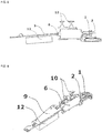
- FIG. 4th shows an embodiment in which the applicator 11 is connected via a connecting part 8 in the form of a hose to the pressure field generating device 1 in order to transmit the pressure alternating field generated by the pressure field generating device 1 to the applicator 11 and to apply it to the penis through the opening 3.
- a first connection 36 of the connecting part 8 is connected to a pneumatic outlet 35 of the pressure field generating device 1, while a second connection 37 of the connecting part 8 is connected to the connection 30 of the applicator 11.
- the connecting part 8 can be configured in sections or completely flexibly.
- the configuration of the stimulation device with a hose as the connecting part 8 can serve the simple use of the stimulation device, since the user only has to hold the applicator 11 with his hand. If necessary, this can also be possible without a tube with a suitable design of the shape of the stimulation device, if necessary with a short connecting piece (cf. for example FIG. 17th ). If a corresponding holding device is provided at the same time, as described in more detail below, a "hands-free" Use possible, since the pressure field generating device 1 (for example, next to or on the user) can be stored.
- a change in cross-section of the pressure chamber 2 or of a pressure or flow system, which in addition to the pressure chamber 2 can also include the fluid channel 7, the connecting part 8 and / or other cavities exposed to the pressure alternating field, can affect the flow velocity of the medium (in particular air), i.e. a cross-sectional constriction means a flow acceleration and a cross-sectional widening correspondingly a flow deceleration.
- a cross-sectional constriction means a flow acceleration and a cross-sectional widening correspondingly a flow deceleration.
- the pressure chamber 2 Since the pressure chamber 2 is placed in an almost sealing manner on the penis and thus an at least largely closed flow system is formed, there is virtually no air exchange with the surroundings, which is why the removal of body fluid from the pressure field generating device is avoided and the stimulation does not lead to the mucous membranes drying out .
- the temperature of the air volume enclosed in the closed system quickly adjusts to the body temperature due to the relatively small volume.
- the stimulation device can do without valves, which facilitates hygienic use.
- a receiving area or receiving space 34 of the applicator 11 defined by a contact area 31 in the area of the tip of the glans 4 is preferably open.
- the stimulation device according to the invention in particular due to the compact shape of the applicator 11, which is preferably set up to stimulate the frenulum 24 and thus only has to seal a small part of the penis against the surroundings, the ejaculate can escape during orgasm. Cleaning is thus simplified. This creates a stimulation device which is improved in terms of hygiene in particular in comparison to conventional closed stimulation devices.
- the stimulation device has, in addition to the pressure field generating device 1, a control device 9 which can control a drive unit 6 and in which the modulation of the pressure field can be pre-stored.
- the control device 9 has at least one control element 10, the respective modulation of the pressure field can be changeable by means of the control element 10.
- the stimulation device has a housing (not shown) which can include the control device 9, the drive unit 6, the pressure field generating device 1 and an internal battery 12, the stimulation device preferably being designed as a portable hand-held device.
- the control device 9 makes it possible to set a stimulation pattern from the stimulation patterns of the control device 9 by means of an operating element 10, the drive unit 6 being controlled in accordance with the set stimulation pattern.
- the drive unit 6 coupled to the flexible wall 5 of the pressure field generating device 1 can consist, for example, of a rotating electric motor 13 with mechanical transmission.
- the mechanical translation of the rotation of the electric motor 13 into a translatory movement of the flexible wall 5 of the pressure field generating device 1 can take place, for example, by means of an eccentric 14, as shown schematically in FIG FIG. 7 shown.
- the drive unit 6 is shown schematically in the form of a rotating electric motor with mechanical translation and coupling to the flexible wall 5 of the pressure field generating device.
- the control current supplied by the rotating electric motor 13 for example in the form of direct current, the rotational speed of the electric motor 13 and thus ultimately the frequency of the flexible wall 5 is varied or controlled.
- the flexible wall 5 can have a bead that mechanically largely follows the strokes of the flexible wall 5 without mechanical stresses.
- the stroke of the flexible wall 5 is determined by the defined eccentric path.
- the fixed piston stroke means a fixed reduction and enlargement of the chamber volume dV and thus correspondingly a fixed pressure increase or pressure reduction, ie an approximately fixed amplitude of the changing overpressure and underpressure.
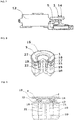
- the drive unit 6 coupled to the flexible wall 5 of the pressure field generating device 1 can consist of a linear electric motor 15, as in FIGS FIG. 8 and 9 shown.
- the flexible wall 5 is connected to a carrier 16 by means of at least one oscillating or immersing coil 17 attached to it and moved in accordance with the coil supply by means of the control current in the air gap 18.
- the flexible wall 5 of the pressure field generating device 1 is fastened to a carrier 16.
- the flexible wall 5 can have a bead that mechanically largely follows the strokes of the flexible wall 5 without mechanical stresses.
- a voice coil 17 is wound around the carrier 16 and is fed in operation by the control current from a control unit.
- the voice coil 17 consists of electrical conductors made of a material which is as electrically conductive as possible (preferably copper) and which are insulated from one another and from the carrier 16 using an electrically insulating lacquer.
- the magnetic field is generated by at least one permanent magnet 19, preferably in the form of a ring.
- the magnetic flux is conducted, for example, by means of a rear pole plate 20 (preferably in the form of a cylinder) via the upper pole plate 21 (preferably in the form of a ring) via the preferably annular air gap to the cylindrical pole core 22.
- the rear pole plate 20 and the upper pole plate 21, like the pole core 22, are made of a magnetically highly permeable material (preferably a soft magnetic material alloy).
- a cylindrical permanent magnet can be used instead of the pole core 22 and, correspondingly, an annular pole instead of the permanent magnet 19.
- the carrier 16 with the voice coil 17 is structurally centered and guided in the air gap 18 by at least one holder or suspension 23 (preferably made of plastic, textile fabric or paper) in order to prevent the voice coil 17 from wobbling.
- the bracket 23 is attached to a frame.
- the voice coil 17 is fed with a control alternating current from a control unit. Depending on the current direction or current polarity, the voice coil 17 is moved up or down in the magnetic field of the air gap 18 by the Lorentz force. The stroke of the deflection of the voice coil 17 is determined by the amplitude of the control current.
- the frequency of the alternating current corresponds to the frequency of the voice coil movement and thus the frequency of the piston or membrane movement. The frequency and the stroke of the voice coil 17 and thus the movement of the flexible wall 5 can thus be controlled relatively easily independently of one another by the current frequency and current amplitude. Due to the direct transmission, an extended frequency range is possible with this principle from less than 1 Hz to several hundred Hz.
- a Direct current from a battery or an accumulator is converted into an alternating current signal.
- the sealing of the pressure chamber 2 from the surroundings is decisive for the construction of the desired pressure alternating field, in particular with the negative and excess pressures mentioned in the order of magnitude of pressure differences of 20 mbar to 800 mbar the penis, in particular the glans 4, and the formation of an at least largely closed flow system.
- the contact area 31 and in particular the sealing device 32 are suitably designed with regard to shape and material, as described below with reference to preferred exemplary embodiments.
- a contact pressure sufficient to build up the above-mentioned negative and positive pressures can be applied to the sealing device 32, as is also described below with the aid of preferred exemplary embodiments.
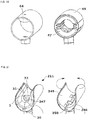
- FIG. 10th An exemplary embodiment of an applicator 11 is shown which, in addition to the sealing device 32, has anatomically shaped projections 33 in the contact area 31.
- the contact area 31 is designed such that it has a surface shape that supports the seal.
- a sealing device 32 is provided which surrounds the opening 3 of the pressure chamber 2 of the applicator 11.
- the sealing device 32 is designed as a rounded, flexible bead around the opening 3, which can adapt to the shape of the penis when the applicator 11 is placed on the penis.
- the projections 33 are provided, which essentially follow the course of the glans ring furrow 25. This can support the sealing effect of the sealing device 32, so that the projections 33 can also be regarded as part of the sealing device 32. Due to their anatomical shape, the projections 33 can facilitate the correct positioning of the applicator 11 on the penis, in particular in such a way that the frenulum 24 is at least partially received in the pressure chamber 2.
- the material of the sealing device 32 is preferably soft, for example a soft silicone or rubber.
- the projections 33 can be made of the same material or of a different, for example harder or softer material be educated.
- the opening 3 of the pressure chamber 2 is designed such that it can at least partially accommodate the frenulum 24, so that the pressure alternating field in the pressure chamber 2 can act directly on the frenulum 24.
- the contact pressure required for a seal can be applied by the user's own hand pressure.
- FIG. 11 Such an applicator 11 is shown schematically, applied to a penis, in which the pressure chamber 2 is sealed against the glans 4 by the contact pressure applied by means of the hand pressure.
- a holding device or gripping device is formed in the form of wing-like extensions 23, which the user can position flexibly on the penis or glans 4. In this way, the sealing device is pressed against the penis.
- the opening 3 is designed to receive the frenulum 24 and parts or the entire glans ring 25.
- the pressure chamber 2 widens towards the opening 3, as in the sectional view in FIG FIG. 11 can be seen.
- the necessary contact pressure can be achieved, for example, by an essentially ring-shaped holding device 26, the material residual stresses occurring when the ring 26 is elastically deformed acting on the penis and on the sealing device.
- the holding device 26 is advantageously open in the region of the tip of the glans 4.
- a cap-like structure closed at the tip is also conceivable, which, like the annular holding device 26, is elastically deformable and thus holds the applicator 11 on the glans 4.
- the opening 3 of the pressure chamber 2 is in the FIG. 12th illustrated embodiment after stretching and placing the annular holding device 26 sealed against the glans 4, the opening 3 receiving the frenulum 24 and parts or the entire glans ring 25.
- ring-shaped and elastically deformable holding device 26 can be reinforced by a belt with a tightening mechanism 27 such as FIG. 13 shown.
- the sealing is achieved by means of the material's internal tension in the event of elastic deformation and additionally by means of a force applied by means of a belt against the glans 4 of the male member.
- the necessary contact pressure can be applied solely by means of a belt-like or band-shaped holding device 26 with a fixing or tightening mechanism 27, as in FIG FIG. 14 shown.
- the strap is particularly easy to fix and position on the glans ring 25.
- this holding device 26 of the applicator 11 can be particularly easily adapted to different diameters of the male member in the area of the glans 4.
- the holding device can be formed separately from the applicator body 29.
- the seal can be improved even with different limb or glans diameters and the use with regard to putting on and taking off the stimulation device and cleaning can be simplified.
- This multi-partness is in FIG. 15 exemplified on the belt sealing system.
- a holding body 28 with a belt separate from the applicator body 29 is arranged above the applicator body 29, so that the necessary contact pressure can be applied to the sealing device.
- the two parts can be made of the same material or different materials.
- the in the FIG. 10 to 15 are designed in particular for stationary or stationary use of the stimulation device or the applicator 11.
- the applicator 11 can be designed, in particular with regard to the shape, in particular the contact area 31 and the sealing device 32, in such a way that it is placed on the penis and, if appropriate, fastened with a holding device, but without being moved.
- the alternating pressure field is applied via the opening 3, in particular to the frenulum 24.
- the applicator can be moved over the penis shaft, the glans ring groove 25, the glans ring and the glans 4.
- a contact pressure or a pressure force is applied, a sealing connection is to be established in order to achieve the stimulation, as in the other exemplary embodiments, by applying the alternating pressure field via the opening 3.
- the applicator according to the embodiments of the FIG. 16 to 21 is designed in such a way that it can be moved along the penis shaft in particular by loosening or at least loosening the contact pressure. However, movement can also be possible while maintaining the contact pressure.
- the sealing device 32 is preferably designed in such a way that, on the one hand, it adapts and seals against the surface of the glans groove and other areas on the penis due to the pressure applied and bulge-like lips around the opening 3 of the pressure chamber 2, and on the other hand when the contact pressure is released or loosened or can move even when applying or maintaining a contact pressure.
- the contact area 31 advantageously extends around the entire circumference of the penis and defines a circumferentially closed receiving space 34 ( FIG. 16 to 20 ), but can also be open in scope ( FIG. 21 ).
- the holding devices described below are also suitable on the one hand for fixing the applicator to the penis, but can be loosened or loosened accordingly in order to allow movement of the applicator along the penis shaft.
- the pressure alternating field can continue to be generated or switched off during a movement.
- the sealing device can form a sliding seal so that even when moving at least partially up to the same or approximately the same sealing effect can be achieved as in stationary operation and the alternating pressure field can be built up in the pressure chamber 2 and applied to the penis through the opening 3.
- FIG. 16 An embodiment of an applicator 111 is shown, which has a circumferentially connected contact area 31 and thus a circumferentially closed receiving space 34, into which the penis can be inserted.
- the applicator 111 has a connection 30, via which a pressure alternating field generated by a pressure field generating device 1 into a pressure chamber 2 of the applicator 111 and finally via the opening 3 onto a part of the penis to be stimulated, such as the frenulum, can be applied.
- a sealing device 32 is formed around the opening 3 in the contact area 31.
- the applicator 111 has a rigid formwork which comprises a first part 45 with the connection 30 and an opposite second part 46.
- a soft insert 47 for example made of silicone, is arranged in the formwork and has the contact area 31 and abuts the penis when in use.
- the parts 45, 46 of the formwork are spaced apart from one another in the unloaded state of the applicator 111 and can be moved towards one another by hand.
- the soft insert 47 is compressed so that the contact pressure the sealing device 32 is enlarged on the penis.
- the compression of the insert 47 can be facilitated by providing one or more notches 48.
- the sealing device 32 is also designed such that it is soft and rounded, for example, so that the applicator 111 can also be moved along the penis shaft. It is possible that an adequate contact pressure and thus an adequate sealing of the pressure chamber 2 for applying an alternating pressure field is achieved even when moving. However, if the contact pressure is too low, the structure of the alternating pressure field can be impaired. Combined stimulation can thus be achieved in use, the applicator 111 being able to be moved, for example, in such a way that, in addition to the friction generated, it lies at least in phases in a sealing position on the penis, so that pneumatic stimulation is generated in these positions by means of the pressure field.
- the sealing position can also be in motion depending on the location of the penis.
- a moving seal in the area of the penis shaft can be simpler than in the area of the glans.
- structures such as knobs, ribs and the like (not shown) can be provided on the surface of the insert 47, that is to say in the contact region 31, in order to increase the stimulation by friction in this case.
- FIG. 17th the applicator 111 is shown connected to a pressure field generating device 1.
- the hand of a user is indicated, which holds the applicator 111 or compresses it if necessary.
- the pneumatic outlet 35 of the pressure field generating device 1 is connected directly to the connection 30 of the applicator 111.
- a connecting part 8 for example a hose, can be arranged between the pressure field generating device 1 and the applicator 111 for the connection.
- FIG. 18th shows part of an embodiment of an applicator 111, which the in FIG. 16 is similar, an increase in the pressing force is also achieved by manually compressing the two parts 45, 46 of the formwork.
- a fixing device is provided which fixes the formwork in a desired position and the contact pressure maintained even after releasing the applicator.
- a latching mechanism 61 is provided, as a result of which the clamping force which arises as a result of the compression is maintained even when no force is exerted on the formwork from outside. This is achieved by interlocking corresponding surface profiles, such as teeth.
- a mechanism 62 is provided, which releases the latching mechanism 61 by suitable displacement of the surface profiles relative to one another.
- an increase in the contact pressure is achieved by means of a clamping device.
- Pulling ropes 63 are tensioned by actuating the tensioning device, for example by means of a rotary knob 60.
- the pull cables 63 can be located in a guide channel (not shown) in the two parts 45 and 46 of the formwork.
- a rotary movement of the rotary knob 60 tensions the pulling ropes 63, as a result of which the parts 45 and 46 are moved towards one another and the contact pressure on the penis is increased.
- the tensioning device preferably has a fixing device (not shown) with a latching function which prevents the applied tensioning force from being released unintentionally. A mechanism for releasing the latching function is advantageously provided.
- an increase in the contact pressure is achieved by means of at least one air cushion 64, which is arranged between the formwork 49 formed here in one piece and the insert 47.
- the air cushion 64 By inflating the air cushion 64, in particular with air, the diameter of the receiving space 34 of the applicator 111 can be reduced at least in sections and the contact pressure on the penis can be increased.
- a one-way valve (not shown) can be provided to release the air from the air cushion 64 and thus reduce the contact pressure again.
- the applicator 211 has a wing-like formwork with a first part 245 and a second part 246, which are connected to one another via a hinge 250 so as to be movable, in particular pivotable.
- the contact area 31 does not completely enclose the penis.
- a torsion spring (not shown) is preferably provided, which forces the parts 245 and 246 of the formwork to move away from one another into an open position.
- a fixing device (not shown) with a snap-in function can be provided which fixes the applicator 211 in a narrowed position caused by a user by applying a force.
- a mechanism for releasing the locked position can also be provided.
- FIG. 22 shows a coupling device 40, which serves in particular as a non-return valve.
- the coupling device 40 is attached between the hose 8 and the applicator 11 or between two sections 38, 39 of the hose 8, the section 38 leading to the pressure field generating device 1, while the section 39 leads to the applicator 11.
- the coupling device 40 is advantageously positioned close to the applicator 11, so that the section 39 of the hose 8 to be cleaned, which points towards the applicator 11, is as short as possible.
- the coupling device 40 has a membrane 41 which divides a cavity of the coupling device 40 into two chambers 42, 43, so that no fluid can get from the chamber 43 into the chamber 42, that is to say in the direction from the applicator 11 to the pressure field generating device 1. in particular due to the pressure alternating field generated by the pressure field generating device 1 causes a deflection of the membrane 41, so that the pressure alternating field is transmitted despite the prevention of a fluid flow.
- the coupling device 40 can be separated by loosening a fastening mechanism 44 and the section 39 of the hose 8 can be cleaned with the applicator 11. It is not necessary to clean the section 38 of the hose 8, since no fluid can get into the section 38 due to the fluid-impermeable membrane 41.
- connection mechanism in the form of a fluid-tight plug connection is shown.
- Any applicator 11 for example one of the applicators described above, can be connected directly to a pressure field generating device 1 by means of the connection mechanism.
- the connection mechanism can be used to connect a connection part 8, for example a hose, to an applicator 11 or a pressure field generating device 1 or both.
- a plug connection allows a stimulation device to be assembled easily.
- the connector shown has a first part 51 with a receptacle into which an extension of a second part 52 can be inserted.
- an O-ring can be provided in at least one of the plug parts or in both.
- any aspects of the preferred exemplary embodiments described above can be combined with one another in a suitable manner.
- the preferred exemplary embodiments are only exemplary.
- various aspects of the applicator such as, for example, sealing device, pressure chamber, opening, contact area, receiving space and holding device, can be combined in any way in order to apply an applicator according to the invention for applying an alternating pressure field to an area of a penis to be stimulated, in particular the glans, preferably the frenulum, to accomplish.
- the applicator can also be connected or connectable directly to a pressure field generating device, or a connection part such as a hose can be provided for this purpose.
- one or more of the applicators described or also several applicators of the same type are provided in a set together with a pressure field generating device and, if appropriate, a suitable connecting part.
Landscapes
- Health & Medical Sciences (AREA)
- Veterinary Medicine (AREA)
- Life Sciences & Earth Sciences (AREA)
- Animal Behavior & Ethology (AREA)
- General Health & Medical Sciences (AREA)
- Public Health (AREA)
- Pain & Pain Management (AREA)
- Epidemiology (AREA)
- Physical Education & Sports Medicine (AREA)
- Rehabilitation Therapy (AREA)
- Reproductive Health (AREA)
- Vascular Medicine (AREA)
- Heart & Thoracic Surgery (AREA)
- Nursing (AREA)
- Biomedical Technology (AREA)
- Engineering & Computer Science (AREA)
- Orthopedic Medicine & Surgery (AREA)
- Orthopedics, Nursing, And Contraception (AREA)
- Percussion Or Vibration Massage (AREA)
Abstract
Description
- Die Erfindung betrifft eine Stimulationsvorrichtung für einen männlichen Penis und insbesondere einen Applikator für eine solche Stimulationsvorrichtung. Die Stimulationsvorrichtung weist eine Druckfelderzeugungseinrichtung zur Erzeugung eines pneumatischen Druckwechselfeldes auf, welches mittels des Applikators auf einen zu stimulierenden Bereich eines Penis appliziert werden kann.
- Es sind verschiedene Stimulationsvorrichtungen für den männlichen Penis bekannt, welche zu einer sexuellen Erregung führen beziehungsweise eine sexuelle Erregung gegebenenfalls bis zum Höhepunkt steigern können. Derartige Stimulationsvorrichtungen weisen üblicherweise einen Aufnahmeraum auf, welcher im Wesentlichen geschlossen ist und eine Öffnung aufweist, in welche der (erigierte) Penis eingeführt werden kann. Oftmals ist das vordere Ende des Aufnahmeraums verschlossen, sodass insbesondere die Eichel des Penis umschlossen ist. Die Innenseite des Aufnahmeraums liegt am Penis an und kann zur Verstärkung der Stimulation Strukturen, wie beispielsweise Noppen aufweisen. Neben manuellen Vorrichtungen, bei denen ein Benutzer selbst gewünschte Bewegungen zur Stimulation durch Reibung ausführen muss, sind automatische Vorrichtungen bekannt.
- Derartige automatische Vorrichtungen können entweder eine manuelle Bewegung nachahmen oder andere stimulationsartige Bewegungen ausführen. Beispielsweise kann der Aufnahmeraum ganz oder teilweise in seiner Form oder seinem Volumen durch auf den Aufnahmeraum wirkende mechanische oder pneumatische Vorrichtungen verändert werden, um eine Stimulation zu erzeugen. Der Aufnahmeraum kann dazu als flexible Hülle aus einem weichen Material gestaltet sein und sich in einem festen Gehäuse befinden, welches neben dem Aufnahmeraum entsprechende Antriebe, Pumpen, Stimulationsköpfe, Batterien und dergleichen beherbergen kann. Bekannt sind auch Stimulationsvorrichtungen, bei denen der Aufnahmeraum am Schaft des Penis abgedichtet wird, sodass mittels eines variierenden Unterdrucks eine Stimulationswirkung erzielt werden kann.
- Da bei den bekannten Vorrichtungen oftmals lediglich eine Stimulationsfunktion realisiert ist, wird der Stimulationseffekt oftmals als nicht zufriedenstellend wahrgenommen. Außerdem wird bei bekannten Stimulationsvorrichtungen zumeist der gesamte Penis in den Aufnahmeraum eingeführt, sodass auch aufgrund des großen Gehäuses diese Vorrichtungen relativ unhandlich sind. Auch sind solche Vorrichtungen meist nur in einer Standardgröße erhältlich und sind für verschiedene Penisgrößen oft unzureichend anpassungsfähig. Durch die geschlossene Form des Aufnahmeraums kann zudem die Reinigung schwierig sein, auch da oftmals Gleitgel oder ähnliches notwendig ist, um Hautreizungen durch Reibung zu vermeiden.
- Aufgabe der vorliegenden Erfindung ist es daher, eine Stimulationsvorrichtung für einen männlichen Penis zu schaffen, welche hinsichtlich Stimulation des Penis und Anwendung verbessert ist.
- Die Aufgabe wird gelöst durch einen Applikator für eine Stimulationsvorrichtung für einen männlichen Penis und eine Stimulationsvorrichtung mit einem solchen Applikator mit den Merkmalen der unabhängigen Ansprüche. Es ist ferner ein Artikel mit einer derartigen Stimulationsvorrichtung und mindestens einem weiteren Applikator vorgesehen.
- Gemäß einem ersten Aspekt ist ein Applikator für eine Stimulationsvorrichtung für einen männlichen Penis geschaffen. Der Applikator umfasst einen Applikatorkörper mit einem Anlagebereich, welcher eingerichtet ist, beim Anlegen an einen Penis hieran wenigstens teilweise zur Anlage zu kommen. Des Weiteren umfasst der Applikator einen Druckraum, welcher an dem Applikatorkörper gebildet und eingerichtet ist, von einer Druckfelderzeugungseinrichtung ein pneumatisches Druckwechselfeld zu empfangen. Der Druckraum weist eine Öffnung im Anlagebereich auf, sodass das Druckwechselfeld über die Öffnung auf einen zu stimulierenden Bereich des Penis applizierbar ist. Eine Dichteinrichtung ist an dem Applikatorkörper gebildet und eingerichtet, beim Anlegen des Applikatorkörpers an den Penis den Druckraum gegenüber der Umgebung abzudichten.
- Gemäß einem weiteren Aspekt ist eine Stimulationsvorrichtung für einen männlichen Penis geschaffen, welche zumindest einen derartigen Applikator und eine Druckfelderzeugungseinrichtung zur Erzeugung eines pneumatischen Druckwechselfeldes umfasst. Die Druckfelderzeugungseinrichtung weist einen pneumatischen Ausgang auf, über welchen ein erzeugtes pneumatisches Druckwechselfeld ausgebbar ist, wobei der pneumatische Ausgang mit dem Applikator verbindbar oder verbunden ist, sodass das pneumatische Druckwechselfeld auf den Druckraum des Applikators übertragbar ist.
- Gemäß noch einem weiteren Aspekt ist ein Artikel mit einer derartigen Stimulationsvorrichtung für einen männlichen Penis und wenigstens einem weiteren derartigen Applikator geschaffen, wobei die in dem Artikel enthaltenen Applikatoren vorzugsweise verschieden sind. Der Artikel kann auch als Set bezeichnet werden und erlaubt einen modularen Aufbau der Stimulationsvorrichtung.
- Gemäß einem bevorzugten Ausführungsbeispiel ist der Applikator lösbar mit der Druckfelderzeugungseinrichtung verbunden, entweder direkt oder mittels eines Verbindungsteils wie unten detaillierter beschrieben, sodass er zur Reinigung oder zum Austausch von der Druckfelderzeugungseinrichtung getrennt und wieder mit dieser verbunden werden kann. Alternativ kann der Applikator jedoch fest mit der Druckfelderzeugungseinrichtung verbunden beziehungsweise integral mit dieser gebildet sein.
- Applikatoren eines Artikels beziehungsweise Sets können insbesondere hinsichtlich Form, Größe, Geometrie und dergleichen verschieden sein. Auch können sich die Applikatoren in weiteren zuvor und im Folgenden beschriebenen funktionalen Teilen, wie beispielsweise der Dichteinrichtung oder der Gestalt des Anlagebereichs unterscheiden. Es kann vorgesehen sein, dass sich die Applikatoren hinsichtlich der Geometrie und/oder Größe ihres Druckraums unterscheiden, wodurch bei gleichbleibendem Betrieb der Druckfelderzeugungseinrichtung Stimulationen unterschiedlicher Intensität bewirkt werden können. Alternativ kann jedoch vorgesehen sein, dass die Applikatoren gleich sind, sodass ein Applikator bei Verlust, Beschädigung, Abnutzung oder dergleichen ersetzt werden kann. Besonders vorteilhaft sind die Applikatoren dazu lösbar mit der Druckfelderzeugungseinrichtung verbindbar, beispielsweise über ein Verbindungsteil wie unten detaillierter beschrieben, welches ebenfalls als Teil des Artikels angesehen werden kann. Der Artikel kann in einer Variante mehr als ein Verbindungsteil umfassen, wobei die Verbindungsteile gleich oder verschieden sein können.
- Mittels des Applikators kann ein von der Druckfelderzeugungseinrichtung erzeugtes Druckwechselfeld auf einen zu stimulierenden Teil des Penis appliziert werden. Dazu wird der Applikator mit dem Anlagebereich auf einen zu stimulierenden Teil des Penis, beispielsweise die Eichel, die Eichelkranzfurche und oder das Frenulum (Vorhautbändchen) aufgelegt, wie weiter unten detaillierter beschrieben wird. Die Öffnung des Druckraums ist im Anlagebereich angeordnet und weist bei Benutzung in Richtung des Penis, sodass im Bereich der Öffnung des Druckraums kein Kontakt zwischen dem Penis und dem Applikator besteht und der Druckraum direkt an die Haut des Penis grenzt. Das Druckwechselfeld wird somit direkt auf den Penis appliziert.
- Im Gegensatz zu bekannten Stimulationsvorrichtung erfolgt die stimulierende Anregung somit durch kontaktloses Übertragen einer Stimulationskraft mittel des Druckwechselfeldes. Insbesondere kommen auch Teile der Druckfelderzeugungseinrichtung, beispielsweise eine flexible Wand oder Membran der Druckfelderzeugungseinrichtung, die zur Druckwechselfelderzeugung entsprechend ausgelenkt wird, nicht in Kontakt mit dem Penis, insbesondere in keiner Phase des Betriebs. Mit anderen Worten, die flexible Wand oder flexible Membran ist zur Öffnung des Druckraums beabstandet und somit auch zur Dichteinrichtung beabstandet, insbesondere von dieser verschieden. Dies ist insbesondere für die Stimulation des empfindlichen Frenulums vorteilhaft, wie unten genauer beschrieben werden wird. Es kann somit ein besonderer Stimulationseffekt geschaffen werden, der sich vom Effekt üblicher taktiler Stimulationsvorrichtungen unterscheidet. Der Applikator ist kompakt und kann einfach an den Penis angelegt werden, sodass er einfach benutzt und auch einfach gereinigt werden kann.
- Die Dichteinrichtung ist derart ausgestaltet, dass beim Anlegen des Applikators an den Penis der Druckraum gegenüber der Umgebung abgedichtet wird. Auf diese Weise kann sich ein Druckwechselfeld aufbauen und der zu stimulierende Teil des Penis, also insbesondere der Teil des Penis, welcher sich im Bereich der Öffnung des Druckraums unmittelbar angrenzend an den Druckraum befindet, mittels des Druckwechselfeldes stimuliert werden.
- Unter Druckwechselfeld wird dabei ein solches variierendes Druckfeld verstanden, welches bezüglich des Umgebungsdrucks sowohl Unterdrücke als auch Überdrücke aufweist, beispielsweise abwechselnde Unterdruckphasen und Überdruckphasen oder in einem anderen vorgegebenen Muster von gegebenenfalls gleichen oder unterschiedlichen Unter- und Überdrücken. Dieses Druckwechselfeld herrscht im Druckraum des Applikators, insbesondere im Bereich der Öffnung des Druckraums, d.h. Parameter, wie Frequenz und Amplitude des Druckwechselfelds sind an der Öffnung zu messen. Der Druck kann dabei mit einer Frequenz von 5 Hz bis 250 Hz wechseln, vorzugsweise 10 Hz bis 200 Hz, weiter vorzugsweise 20 Hz bis 100 Hz, beispielsweise 60 Hz. Die Druckdifferenz kann 20 mbar bis 800 mbar betragen, vorzugsweise 50 mbar bis 750 mbar, weiter vorzugsweise 100 mbar bis 700 mbar, beispielsweise 200 mbar, wobei die Druckdifferenz zwischen dem höchsten Überdruck und dem niedrigsten Unterdruck besteht und vorzugsweise symmetrisch um einen Umgebungsdruck angeordnet ist. Bei einem Normaldruck der Umgebung von etwa 1 bar kann das Druckwechselfeld beispielsweise zu einem Druck von 0,7 bar bis 1,3 bar in dem Druckraum führen, was einer Druckdifferenz von 0,6 bar (600 mbar) entspricht. Das Druckwechselfeld ist insbesondere ein pneumatisches Druckwechselfeld, d. h. als Druckmedium wird insbesondere Luft verwendet. Es ist jedoch denkbar, dass das Druckwechselfeld über ein anderes Medium übertragen wird, beispielsweise über ein Fluid, wie Wasser, Gel oder dergleichen, welches in den Druckraum eingebracht wird.
- Die Dichteinrichtung ist somit insbesondere dazu eingerichtet, den Druckraum sowohl bezüglich Unterdrücken als auch Überdrücken relativ zu einem Umgebungsdruck der Umgebung gegen die Umgebung abzudichten. Mit anderen Worten, die Dichteinrichtung ist eingerichtet, Strömungen, insbesondere Luftströmungen, in beide Richtungen, d.h. aus dem Druckraum in die Umgebung und von der Umgebung in den Druckraum zu verhindern oder zumindest annähernd zu verhindern. Zur Umgebung gehören insbesondere Bereiche außerhalb des Druckraums oder außerhalb des Applikators.
- Die Dichteinrichtung kann insbesondere im Anlagebereich gebildet und eingerichtet sein, beim Anlegen des Applikatorkörpers zumindest abschnittsweise am Penis zur Anlage zu kommen, um den Druckraum gegenüber der Umgebung abzudichten. Insbesondere kann die Dichteinrichtung um die Öffnung des Druckraums herum umlaufend gebildet sein, beispielsweise kreisförmig, oval oder dergleichen. Die Dichteinrichtung kann dabei auch derart ausgebildet sein, dass sie mehrere Abschnitte umfasst, welche sich beim Aufbringen eines Anpressdrucks elastisch verformen, um eine umlaufende Dichtung zur Abdichtung des Druckraums gegenüber der Umgebung zu bilden.
- Es versteht sich, dass die Dichteinrichtung auch andere Formen aufweisen kann, die zur dichtenden Anlage am Penis geeignet sind. Insbesondere ist jedoch vorzugsweise vorgesehen, dass die Dichteinrichtung den Penis nicht umlaufend umschließt, sondern seitlich am Penis anliegt, beispielsweise im Bereich des Frenulums. Die Dichteinrichtung kann alternativ oder zusätzlich auch zumindest abschnittweise in einem äußeren Randbereich des Applikatorkörpers gebildet sein, insbesondere im Anlagebereich.
- Die Dichteinrichtung kann als erhabene Struktur im Anlagebereich ausgebildet sein und kann beispielsweise eine Dichtlippe, eine Dichtmembran, einen Wulst, einen Vorsprung oder dergleichen aufweisen. Vorteilhaft ist die Dichteinrichtung aus einem weichen Material gebildet, sodass sie sich beim Anlegen an den Penis den anatomischen Gegebenheiten anpasst und dichtend an der Haut des Penis anliegt. Die Dichteinrichtung kann zum Beispiel ein rundes, beispielsweise halbkreisförmiges Querschnittsprofil aufweisen. Es kann ein Anpressdruck auf die Dichteinrichtung aufgebracht werden, um die Abdichtung zu verbessern. Dies kann manuell oder durch eine Halteeinrichtung erfolgen, wie unten detaillierter beschrieben wird.
- Die Dichteinrichtung kann insbesondere dazu ausgebildet sein, den Druckraum abzudichten, wenn der Applikator stationär am Penis anliegt, d. h. nicht bewegt wird. Die Dichteinrichtung kann jedoch derart beschaffen und als Gleitdichtung ausgebildet sein, dass zumindest eine teilweise Abdichtung des Druckraums oder auch eine annähernde Dichtung wie im unbewegten Zustand auch bei einer Bewegung des Applikators entlang des Penis erreicht wird. Vorteilhaft ist die Dichteinrichtung derart ausgebildet, dass sie trotz effektiver Abdichtung im unbewegten Zustand eine Bewegung des Applikators entlang des Penis zulässt oder zumindest nicht behindert. Beispielsweise kann die Dichteinrichtung dazu besonders weich und abgerundet ausgebildet sein. Gegebenenfalls kann bei einer Bewegung des Applikators durch die Dichteinrichtung eine zusätzliche Stimulation des Penis erreicht werden, wenn die Dichteinrichtung als erhabene Struktur im Anlagebereich ausgebildet ist.
- Im Anlagebereich des Applikatorkörpers kann zumindest ein anatomisch geformter Vorsprung angeordnet sein, welcher vorzugsweise zumindest abschnittsweise dem Verlauf einer Eichelkranzfurche des Penis folgt. Der anatomisch geformte Vorsprung kann mit der Dichteinrichtung verbunden oder von dieser getrennt sein. Er kann die Dichtwirkung unterstützen und auch dazu dienen, eine korrekte Positionierung des Applikators am Penis zu erleichtern. Der anatomisch geformte Vorsprung kann hinsichtlich seiner Lage, seines Verlaufs und/oder seines Querschnittprofils an die gewünschte Anatomie angepasst sein. Beispielsweise kann der Vorsprung zumindest einem Teil der Eichelkranzfurche, beispielsweise im Bereich des Frenulums folgen. In diesem Fall kann der anatomisch geformte Vorsprung aus zwei Abschnitten gebildet sein, die einen Winkel einschließen. Der Vorsprung kann wie die Dichteinrichtung beispielsweise als Wulst oder Lippe ausgebildet sein.
- Der Druckraum, welcher auch als Applikationsraum bezeichnet werden kann, ist vorzugsweise dazu eingerichtet, beim Anlegen des Applikatorkörpers an den Penis ein Frenulum des Penis zumindest teilweise aufzunehmen. Insbesondere ist die Öffnung des Druckraums im Anlagebereich des Applikatorkörpers dazu entsprechend bemessen und geformt. dass sie das Frenulum zumindest teilweise oder vollständig umgibt. Beispielsweise kann die Öffnung für die gesamte oder teilweise Aufnahme des Frenulums einen Durchmesser kleiner als 40 mm, vorzugsweise kleiner als 30 mm, weiter vorzugsweise kleiner als 20 mm aufweisen.
- Da der Druckraum zum Penis hin offen ist, kann das Druckwechselfeld somit auf diese Weise direkt auf das Frenulum einwirken, beispielsweise durch leichtes Hineinziehen des Frenulums in den Druckraum in den Unterdruckphasen. Die Art der Stimulation durch ein pneumatisches Druckwechselfeld ist besonders effektiv, da die erogene Zone in der Unterdruckphase durch eine verstärkte Durchblutung sensibilisiert und in der Überdruckphase stimuliert wird. Diese Region des Penis zählt zu den stärksten erogenen Zonen des männlichen Körpers, sodass eine geeignete Stimulation zu sexueller Erregung führen beziehungsweise sexuelle Erregung steigern kann. Insbesondere die Stimulation mittels eines Druckwechselfeldes, also das kontaktlose Aufbringen einer Stimulationskraft, ist für das sensible Frenulum besonders geeignet.
- Der Applikator kann einen Anschluss aufweisen, welcher an dem Applikatorkörper angeordnet und eingerichtet ist, an eine Druckfelderzeugungseinrichtung angeschlossen zu werden und von dieser ein pneumatisches Druckwechselfeld zu empfangen, wobei der Druckraum mit dem Anschluss fluidisch verbunden ist. Insbesondere ist es vorteilhaft, einen Anschluss vorzusehen, wenn der Applikator lösbar mit einer Druckfelderzeugungseinrichtung verbindbar ist. Insbesondere kann die Druckfelderzeugungseinrichtung auf einer Seite des Anschlusses und der Druckraum auf einer anderen, insbesondere gegenüberliegenden Seite des Anschlusses angeordnet sein. Beispielsweise eine zur Druckwechselfelderzeugung eingerichtete flexible Membran bildet somit keine Begrenzung des Druckraums, sondern ist außerhalb des Druckraums, vorzugsweise vom Druckraum beabstandet angeordnet.
- In dem Applikatorkörper kann ein Fluidkanal gebildet sein, über welchen der Anschluss und der Druckraum fluidisch miteinander verbunden sind. Insbesondere kann der Fluidkanal einen kleineren Querschnitt aufweisen als der Druckraum beziehungsweise der Druckraum einen größeren Querschnitt als der Fluidkanal. Auf diese Weise kann das Druckwechselfeld effektiv vom Anschluss in den Druckraum übertragen werden.
- Die Öffnung des Druckraums kann beispielsweise den gleichen Querschnitt wie der Druckraum aufweisen, sodass das Druckwechselfeld auf einer möglichst großen Fläche auf den zu stimulierenden Teil des Penis appliziert werden kann. Gleichzeitig kann der Anschluss an die Druckerzeugungseinrichtung im Querschnitt klein gehalten werden.
- Um die Fläche, auf welche das Druckwechselfeld auf den Penis einwirkt, also insbesondere die Fläche der Öffnung des Druckraums im Anlagebereich weiter zu vergrößern, kann sich der Druckraum zur Öffnung hin erweitern. Alternativ kann der Druckraum jedoch einen gleich bleibenden Querschnitt aufweisen und beispielsweise zylindrisch ausgebildet sein.
- Umgekehrt kann vorgesehen sein, dass sich der Querschnitt des Druckraums zur Öffnung hin verkleinert. Beispielsweise kann unabhängig davon auch ein Querschnitt des Fluidkanals und/oder Anschlusses größer sein als ein Querschnitt des Druckraums und/oder der Öffnung. Auf diese Weise kann der Druck im Bereich der Öffnung verstärkt werden. Auch kann unabhängig von der Geometrie des Druckraums die Öffnung eine kleinere Querschnittsfläche aufweisen als der an die Öffnung angrenzende Bereich des Druckraums.
- Eine anschlussseitige Öffnung des Druckraums, über die das pneumatische Druckwechselfeld in den Druckraum einleitbar ist, kann der Öffnung des Druckraums im Anlagebereich des Applikatorkörpers gegenüberliegend angeordnet sein. Diese Anordnung ist vorteilhaft für die Übertragung des Druckwechselfeldes von der Druckerzeugungseinrichtung über den Anschluss in den Druckraum bis hin zur Öffnung des Druckraums und schließlich auf den Penis, da die Druckkräfte entlang einer Achse wirken. Alternativ kann es jedoch vorgesehen sein, dass der Anschluss an einer anderen Stelle im Applikator relativ zum Druckraum angeordnet ist, beispielsweise seitlich im Druckraum. Falls wie oben erwähnt ein Fluidkanal vorgesehen ist, kann der Fluidkanal entweder geradlinig verlaufen oder einen beliebigen anderen gekrümmten oder abgewinkelten Verlauf einnehmen, um den Anschluss mit dem Druckraum fluidisch zu verbinden.
- Der Anlagebereich des Applikatorkörpers kann einen Aufnahmeraum definieren, welcher durch den Anlagebereich begrenzt und eingerichtet ist, den Penis zumindest teilweise aufzunehmen, sodass der Anlagebereich entlang zumindest eines Teils des Umfangs des Penis anliegt. Da die Öffnung des Druckraums im Anlagebereich angeordnet ist, mündet sie direkt in den Aufnahmeraum. Mit anderen Worten, wie oben bereits beschrieben, ist der Druckraum zum Aufnahmeraum hin und damit auch zum Penis hin offen, wenn der Applikator am Penis anliegt, sodass das Druckwechselfeld direkt auf die Haut des Penis, beispielsweise das Frenulum, einwirken kann. Die Öffnung des Druckraums und die Dichteinrichtung können somit insbesondere in einer durch den Anlagebereich definierten Anlagefläche liegen.
- Der Aufnahmeraum kann insbesondere zwei entlang einer Längsrichtung gegenüberliegende offene Enden aufweisen, wobei der Penis durch eines der Enden in den Applikator eingeführt werden und gegebenenfalls aus dem anderen Ende wieder austreten kann. Hierzu kann der Aufnahmeraum beispielsweise symmetrisch bezüglich einer Ebene senkrecht zur Längsachse ausgebildet sein. Der Aufnahmeraum kann entlang seines Umfangs geschlossen oder offen sein. Wenn der Aufnahmeraum entlang des Umfangs offen ist, liegt der Anlagebereich nur entlang eines Teils des Umfangs des Penis an, beispielsweise in einem Bereich, welcher das Frenulum umfasst.
- Der Aufnahmeraum kann weit geöffnet sein, sodass der Anlagebereich lediglich an einem Teil des Umfangs des Penis, beispielsweise entlang eines Viertels bis zur Hälfte des Umfangs anliegt. Zur Stimulation des Frenulums kann es insbesondere ausreichend sein, wenn der Anlagebereich nur auf der Unterseite des Penis anliegt. Dies erlaubt eine besonders kompakte Ausgestaltung des Applikators und ein einfaches Anlegen, ohne dass der Penis in den Applikator eingeführt werden muss.
- In anderen Ausgestaltungen kann der Anlagebereich den Penis weiter umgeben, und beispielsweise an mehr als der Hälfte des Umfangs des Penis bis hin zum gesamten Umfang zur Anlage kommen. Dies kann den Halt des Applikators am Penis verbessern, erfordert jedoch gegebenenfalls das Einführen des Penis in den Applikator.
- Der Anlagebereich beziehungsweise der Aufnahmeraum kann durch ein besonders weiches Material gebildet sein, welches sich an die Oberfläche des Penis anschmiegt, beispielsweise ein Silikon oder eine Silikonmischung mit einer geringen Shore-Härte, zum Beispiel kleiner als 5, vorzugsweise kleiner als 3, weiter vorzugsweise kleiner als 2. Es kann auch ein selbstschmierendes Silikon verwendet werden, um den Einsatz von Gleitgel zu vermeiden oder zu reduzieren, insbesondere falls es beabsichtigt ist, den Applikator zu bewegen. Zur Verstärkung der Stimulation bei einer Bewegung des Applikators entlang des Penis, kann der Anlagebereich mit erhabenen Strukturen, wie beispielsweise Noppen, Rippen oder dergleichen versehen sein. Der Druckraum und der Anschluss des Applikators können in einem Teil des Applikators gebildet sein, welcher aus einem steiferen Material gebildet ist und welches beispielsweise eine Schalung um eine weiche Einlage herum bilden kann, welche den Anlagebereich bildet. Als Material kann dafür beispielsweise ein Silikon oder eine Silikonmischung mit einer höheren Shore-Härte, zum Beispiel größer als 20, vorzugsweise größer als 30, weiter vorzugsweise größer als 40, oder ein harter Kunststoff, wie beispielsweise Acrylnitril-Butadien-Styrol (ABS) und dergleichen verwendet werden.
- Alternativ kann der Applikator insgesamt aus einem Material bestehen, insbesondere aus einem Stück hergestellt sein. Hierzu eignen sich insbesondere Kunststoffe, welche einerseits nicht zu hart sind und sich zur Anlage am Penis eignen und andererseits zur Ausbildung des Druckraums und des Anschlusses ausreichende Steifigkeit aufweisen, wie Silikone oder geeignete Silikonmischungen. Der Applikator dabei mittels Spritzgussverfahren und insbesondere auch im Zwei- oder Mehrkomponenten-Spritzgussverfahren hergestellt werden, wobei Silikone unterschiedlicher Härte zu einem Teil zusammengefügt werden.
- Der Applikator kann des Weiteren eine Halteeinrichtung umfassen, die eingerichtet ist, den Applikatorkörper nach einem Anlegen an dem Penis zu halten. Unter "Halteeinrichtung" werden dabei insbesondere solche Einrichtungen verstanden, welche den Applikator ohne Festhalten durch den Benutzer nach dem Anlegen am Penis an Ort und Stelle halten, ohne dass er herunterfällt. Insbesondere ist die Halteeinrichtung derart ausgebildet, dass sie den Applikator an einer Stelle am Penis hält, bei welcher sich die Öffnung des Druckraums über einem zu stimulierenden Teil des Penis, beispielsweise über dem Frenulum, befindet. Dadurch kann der Applikator "freihändig" benutzt werden, ohne dass der Benutzer den Applikator festhalten muss.
- Alternativ kann die Halteeinrichtung dazu dienen, das Halten des Applikators durch den Benutzer zu erleichtern. In diesem Fall kann die Halteeinrichtung beispielsweise auch als "Greifeinrichtung" bezeichnet werden. Es können beispielsweise flexible Flügel vorgesehen sein, welche sich um zumindest einen Teil des Umfangs des Penis legen können und so das Halten des Applikators mit der Hand erleichtern. Es versteht sich, dass andere griffartige Strukturen, die das Festhalten des Applikators erleichtern, ebenfalls denkbar sind.
- Die Halteeinrichtung kann sich von dem Applikatorkörper erstrecken und eingerichtet sein, an zumindest einem Teil des Umfangs des Penis zur Anlage zu kommen. Dies ist insbesondere dann vorteilhaft, wenn sich der Anlagebereich des Applikatorkörpers nur über einen Teil des Umfangs des Penis erstreckt. Die Halteeinrichtung kann sich dann vom Applikatorkörper über zumindest einen Teil des Restes oder den gesamten Rest des Umfangs des Penis erstrecken. Die Halteeinrichtung kann beispielsweise Flügel, Bänder, Riemen oder dergleichen aufweisen. Es können gegebenenfalls Mittel zum Befestigen oder Festziehen der Bänder oder Riemen vorgesehen sein. Ferner kann die Halteeinrichtung beispielsweise eine gegebenenfalls flexible, ringartige Struktur, welche sich um den Umfang des Penis herum erstreckt, umfassen. Unabhängig von der Ausgestaltung der Halteeinrichtung kann die Halteeinrichtung lösbar oder fest mit dem Applikatorkörper verbunden sein.
- Die Halteeinrichtung kann eingerichtet sein, einen Anpressdruck der Dichteinrichtung an den Penis zu erhöhen. Mit anderen Worten, anstatt den Applikator lediglich festzuhalten, kann die Halteeinrichtung einstellbar sein, um den Anpressdruck der Dichteinrichtung zu verändern. Beispielsweise kann die Halteeinrichtung Mittel zum Festziehen umfassen, wobei beispielsweise ein Innendurchmesser des Aufnahmeraums verkleinert werden kann, sodass sich der Anpressdruck der Dichteinrichtung auf den Penis erhöht. Anstatt eines Mechanismus zum Festziehen kann der Applikator auch eine Andruckeinrichtung, beispielsweise in Form eines oder mehrerer Luftkissen aufweisen, welche aufgepumpt werden können, um den Sitz des Applikators am Penis zu verstärken und den Anpressdruck zu erhöhen.
- Es kann beispielsweise vorgesehen sein, dass der Applikator eine äußere Schalung aufweist, welche aus zwei oder mehreren Teilen bestehen kann, die derart relativ zueinander bewegt, beispielsweise verschoben oder verschwenkt werden können, dass sich ein Innendurchmesser des Aufnahmeraums verkleinert. Durch Erhöhen des Anpressdrucks kann die Stimulationswirkung gegebenenfalls erhöht werden und das Risiko des Abrutschens des Applikators kann reduziert werden. Alternativ, insbesondere falls die Halteeinrichtung lediglich als Greifeinrichtung ausgebildet ist, kann der Anpressdruck auch mit der Hand erhöht werden.
- Die Halteeinrichtung kann eine Fixiereinrichtung aufweisen, um die Halteeinrichtung in einer gewünschten Stellung zu fixieren. Insbesondere kann auf diese Weise ein gewünschter Anpressdruck gehalten werden, ohne dass der Benutzer den Applikator oder die Halteeinrichtung mit der Hand festhalten muss. Die Fixiereinrichtung kann beispielsweise einen Rastmechanismus umfassen, welcher ein Lösen der Haltevorrichtung nach dem Festziehen verhindert. Es können entsprechende Mittel zum Lösen der Fixiereinrichtung, beispielsweise ein Knopf oder Hebel, vorgesehen sein, sodass der Applikator vom Penis entfernt oder zumindest der Anpressdruck auf den Penis verringert werden kann.
- Wie oben bereits erwähnt kann die Stimulationsvorrichtung ein Verbindungsteil zum Verbinden des Applikators mit der Druckfelderzeugungseinrichtung umfassen. Das Verbindungsteil kann einen ersten Anschluss aufweisen, welcher eingerichtet ist, mit dem pneumatischen Ausgang der Druckfelderzeugungseinrichtung fluidisch verbunden zu werden, und einen zweiten Anschluss, welcher eingerichtet ist, mit dem Anschluss des Applikators fluidisch verbunden zu werden, sodass das pneumatische Druckwechselfeld mittels des Verbindungsteils von der Druckfelderzeugungseinrichtung auf den Druckraum des Applikators übertragbar ist.
- Das Verbindungsteil kann als separates Teil bereitgestellt sein und sowohl mit dem Applikator als auch der Druckfelderzeugungseinrichtung lösbar verbindbar sein. Dies erlaubt einen modularen Aufbau der Stimulationsvorrichtung, insbesondere falls mehrere, gegebenenfalls verschiedene Applikatoren zur Anwendung kommen sollen. Ferner wird die Reinigung der Stimulationsvorrichtung erleichtert, sodass die Hygiene verbessert werden kann. Das Verbindungsteil kann jedoch mit dem Applikator oder der Druckfelderzeugungseinrichtung oder beiden fest verbunden sein. Das Verbindungsteil kann beispielsweise als Schlauch, insbesondere flexibler Schlauch, als Rohr oder eine andere geeignete Struktur umfassen, welche einen entsprechenden Hohlraum zur Übertragung des Druckwechselfeldes von der Druckerzeugungseinrichtung zum Anschluss des Applikators aufweist.
- Ein Schlauch, insbesondere ein längerer Schlauch, erlaubt eine räumliche Distanz zwischen dem Applikator und der Druckfelderzeugungseinrichtung, was eine freihändige Benutzung der Stimulationsvorrichtung erleichtern kann, da die Druckfelderzeugungseinrichtung beispielsweise neben dem Benutzer abgestellt werden kann. Ein kurzes Verbindungsteil oder eine direkte Verbindung der Druckfelderzeugungseinrichtung mit dem Anschluss des Applikators erlaubt ein kompaktes Design der Stimulationsvorrichtung, wobei die Stimulationsvorrichtung im Betrieb dann jedoch möglicherweise aufgrund des höheren Gewichts der Gesamtvorrichtung verglichen mit dem Applikator alleine mit der Hand gehalten werden muss.
- Vorteilhaft kommen Steckverbindungen zum Verbinden des Verbindungsteils mit der Druckfelderzeugungseinrichtung und dem Applikator oder zur direkten Verbindung des Applikators mit der Druckfelderzeugungseinrichtung zum Einsatz. Dies erlaubt eine schnelle und einfache Verbindung, sodass die Anwendung der Stimulationsvorrichtung erleichtert wird. Die Steckverbindungen können entsprechende Dichtungen, wie Dichtlippen, O-Ringe oder dergleichen, aufweisen oder von sich aus ausreichend dicht sein, um das Druckwechselfeld im Wesentlichen ohne Verluste zu übertragen. Es versteht sich, dass auch andere Verbindungsmechanismen, wie Schraubverbindungen, Bajonettverbindungen, Schnappverbindungen oder dergleichen möglich sind.
- Das Verbindungsteil kann eine Koppelungseinrichtung aufweisen, welche zwischen dem ersten Anschluss und dem zweiten Anschluss angeordnet und eingerichtet ist, das pneumatische Druckwechselfeld zu übertragen und einen Fluidfluss zu verhindern, insbesondere einen Fluidfluss vom zweiten Anschluss zum ersten Anschluss, also vom Applikator zur Druckfelderzeugungseinrichtung. Dadurch kann vermieden werden, dass Wasser, Körperflüssigkeiten oder andere Verschmutzungen von der Öffnung des Druckraums über den Druckraum und den Anschluss des Applikators in das Verbindungsteil und möglicherweise sogar in die Druckfelderzeugungseinrichtung gelangen, was insbesondere durch Kapillarkräfte in einem dünnen Schlauch verursacht werden könnte. Die Koppelungseinrichtung dient somit als Rückflussverschluss.
- Vorteilhaft ist die Koppelungseinrichtung zwischen dem ersten und zweiten Anschluss des Verbindungsteils näher am zweiten Anschluss, also näher am Applikator angeordnet, um denjenigen Teil des Verbindungsteils, in den potentiell Flüssigkeiten gelangen können, möglichst klein zu halten. Gegebenenfalls kann die Koppelungseinrichtung direkt am zweiten Anschluss gebildet sein oder den Anschluss zum Applikator bilden. Die Koppelungseinrichtung kann trennbar sein, sodass ein erster Teil des Verbindungsteils mit der Druckfelderzeugungseinrichtung verbunden bleiben kann und ein zweiter Teil des Verbindungsteils, welcher sich zwischen der Koppelungseinrichtung und dem Applikator befindet, separat gereinigt werden kann.
- Durch Vorsehen einer Koppelungseinrichtung kann vermieden werden, dass Fluide vom Applikator durch das Verbindungsteil fließen. Gleichzeitig erlaubt die Koppelungseinrichtung in der umgekehrten Richtung eine Übertragung des Druckwechselfeldes von der Druckerzeugungseinrichtung zum Applikator. Dazu kann die Koppelungseinrichtung eine flexible und fluidundurchlässige Membran aufweisen. Insbesondere kann die Membran undurchlässig für Fluide jeglicher Viskosität sein. Es kann jedoch alternativ oder zusätzlich jedoch auch eine semi-permeable Membran und/oder eine andere Filtereinrichtung vorgesehen sein, welche zumindest Feststoffe aufhält.
- Die Membran kann eine Trennung zwischen zwei Kammern in der Koppelungseinrichtung bilden, wobei sich eine der Kammern auf der der Druckfelderzeugungseinrichtung zugewandten Seite der Membran und die andere der Kammern auf der dem Applikator zugewandten Seite der Membran befindet. Die Kammern erlauben eine Auslenkung der flexiblen Membran, um das Druckwechselfeld zu übertragen. Dazu ist eine Querschnittsfläche der Koppelungseinrichtung vorzugsweise größer als die des Verbindungsteils.
- Die Erfindung wird im Folgenden beispielhaft anhand der begleitenden Zeichnungen beschrieben. Die Zeichnungen zeigen zum besseren Verständnis der Erfindung lediglich schematisch bevorzugte Ausführungsbeispiele der Erfindung, wobei die Erfindung nicht auf die gezeigten bevorzugten Ausführungsbeispiele beschränkt ist.
-
FIG. 1 zeigt einen männlichen Penis. -
FIG. 2 zeigt ein Ausführungsbeispiel einer Stimulationsvorrichtung. -
FIG. 3 zeigt ein weiteres Ausführungsbeispiel einer Stimulationsvorrichtung. -
FIG. 4 zeigt noch ein weiteres Ausführungsbeispiel einer Stimulationsvorrichtung. -
FIG. 5 zeigt ein Ausführungsbeispiel einer Druckfelderzeugungseinrichtung. -
FIG. 6 zeigt die Druckfelderzeugungseinrichtung ausFIG. 5 in einer perspektivischen Ansicht. -
FIG. 7 zeigt eine Antriebseinheit der Druckfelderzeugungseinrichtung. -
FIG. 8 zeigt einen elektrischen Antrieb einer Druckfelderzeugungseinrichtung. -
FIG. 9 zeigt eine andere Ansicht des elektrischen Antriebs ausFIG. 8 . -
FIG. 10 zeigt ein Ausführungsbeispiel eines Applikators in verschiedenen Ansichten. -
FIG. 11 zeigt ein weiteres Ausführungsbeispiel eines Applikators, angelegt an einen Penis, in verschiedenen Ansichten. -
FIG. 12 zeigt ein weiteres Ausführungsbeispiel eines Applikators, angelegt an einen Penis, in verschiedenen Ansichten. -
FIG. 13 zeigt ein weiteres Ausführungsbeispiel eines Applikators, angelegt an einen Penis, in verschiedenen Ansichten. -
FIG. 14 zeigt ein weiteres Ausführungsbeispiel eines Applikators, angelegt an einen Penis, in verschiedenen Ansichten. -
FIG. 15 zeigt ein weiteres Ausführungsbeispiel eines Applikators, angelegt an einen Penis, in verschiedenen Ansichten. -
FIG. 16 zeigt ein weiteres Ausführungsbeispiel eines Applikators. -
FIG. 17 zeigt eine Stimulationsvorrichtung mit dem Applikator ausFIG. 16 . -
FIG. 18 zeigt eine Halteeinrichtung eines Applikators. -
FIG. 19 zeigt ein weiteres Ausführungsbeispiel eines Applikators und dessen Halteeinrichtung. -
FIG. 20 zeigt ein weiteres Ausführungsbeispiel eines Applikators. -
FIG. 21 zeigt ein weiteres Ausführungsbeispiel eines Applikators. -
FIG. 22 zeigt eine Koppelungseinrichtung für ein Verbindungsteil zwischen einem Applikator und einer Druckfelderzeugungseinrichtung. -
FIG. 23 zeigt ein Ausführungsbeispiel einer Steckverbindung. - Zum besseren Verständnis der Erfindung werden mit Bezug auf
FIG. 1 relevante Aspekte der Anatomie eines menschlichen, männlichen Penis (beziehungsweise Glieds), insbesondere hinsichtlich einer gewünschten Stimulation mittels einer Stimulationsvorrichtung gemäß der Erfindung erläutert. Die Eichel 4 und das Frenulum 24 des männlichen Glieds gehören zu den stärksten erogenen Zonen des männlichen Körpers, wobei eine geeignete Stimulation beziehungsweise Reizung zu sexueller Erregung führen beziehungsweise sexuelle Erregung steigern kann. Die sexuelle Erregung kann zum männlichen Orgasmus und Ejakulationsreflex führen. Auch kann durch einen Unterdruck die Durchblutung des stimulierten Bereichs gefördert und durch einen Überdruck eine stimulierende Kraft aufgebracht werden. - Das Frenulum 24 und die Eichelkranzfurche 25, d.h. der Übergang zwischen Eichel 4 und Penisschaft, sind besonders sensibel für die genannte Stimulation beziehungsweise Reizung.
- Mit einer Stimulationsvorrichtung gemäß der Erfindung, insbesondere mit einem entsprechenden erfindungsgemäßen Applikator ist es möglich, die Eichel 4 des männlichen Glieds, insbesondere das Frenulum, im ständigen Wechsel von Über- und Unterdrücken in geeigneter Stärke zu durchbluten und zu stimulieren, so dass eine in ihrer Frequenz und Amplitude geeignete Druckfeldstimulation zur sexuellen Erregung des Mannes, im besten Fall bis zum männlichen Orgasmus, führt.
- Um ein zur sexuellen Stimulation geeignetes Druckwechselfeld (im Folgenden auch einfach Druckfeld genannt) mit ausreichender Stärke aufbauen zu können, ist wie nachfolgend erläutert ein Applikator mit einer Öffnung vorgesehen, um ein mittels einer Druckfelderzeugungseinrichtung erzeugtes Druckwechselfeld direkt auf die Haut des Penis zu applizieren. Der Applikator ist an die Anatomie des männlichen Glieds angepasst und insbesondere zum Auflegen über das Frenulum 24 und die Eichelkranzfurche 25, sowie auch insbesondere zur Aufnahme des Frenulums 24 konzipiert. Durch Vorsehen einer Dichteinrichtung kann das zur Stimulation erforderliche Druckwechselfeld im ausreichenden Maße aufgebaut werden, indem ein Druckraum des Applikators gegen die Umgebung abgedichtet wird.
- Die Stimulationsvorrichtung ist derart gestaltet, dass die Stimulation nicht zu einem Austrocknen der Schleimhäute führt, was beispielsweise durch einen ständigen Luftaustausch mit der Umgebung passieren würde. Außerdem ist die Vorrichtung für eine hygienische Benutzung gestaltet, d.h. schwer zugängliche und damit schwer zu reinigende Hohlräume, in denen sich beispielsweise Körperflüssigkeit sammeln können, wie zum Beispiel in Ventilen, werden vermieden. Darüber hinaus kann sich die Temperatur des in dem Druckraum des Applikators eingeschlossenen, relativ kleinen Luftvolumens schnell der Körpertemperatur angleichen, sodass eine angenehme Benutzung gewährleistet wird. Zudem ist die Stimulationsvorrichtung einfach im Aufbau und damit einfach in der Benutzung, sodass eine Ablenkung des Nutzers bei der Benutzung und der Aufwand zur Benutzung minimiert sind.
- Als geeignete sexuelle Stimulation der Eichel 4 des männlichen Glieds, bestenfalls bis zum Orgasmus, ist insbesondere eine vergleichsweise hochfrequente Wechselfrequenz zwischen 5 Hz bis 250 Hz und eine Druckdifferenz von 20 mbar bis 800 mbar um den Umgebungsdruck von in etwa 1 bar, vorzugsweise symmetrisch um den Umgebungsdruck, vorteilhaft. Ein derartiges Druckwechselfeld bestehend aus einem Wechsel von Unter- und Überdrücken mit einer Wechselfrequenz zwischen 5 Hz bis 250 Hz und Druckdifferenzen von 20 mbar bis 800 mbar kann mittels einer Druckfelderzeugungseinrichtung generiert werden, die in den
FIG. 2 bis 9 schematisch dargestellt ist. Verschiedene Ausführungsbeispiele von Applikatoren sind in denFIG. 10 bis 21 dargestellt. Es versteht sich, dass die verschiedenen Ausführungsbeispiele oder Aspekte der verschiedenen Ausführungsbeispiele beliebig kombiniert werden können. - In
FIG. 2 ist ein erstes Ausführungsbeispiel einer Stimulationsvorrichtung mit einer Druckfelderzeugungseinrichtung 1 dargestellt. Die Druckfelderzeugungseinrichtung 1 weist zumindest eine Wand 5 oder Membran auf, welche aus einem elastischen Material, beispielsweise Silikon oder Gummi, besteht, wobei diese flexible Wand 5 mittels eines Antriebs 6 ausgelenkt wird, um eine positive und negative Volumenänderung dV in der Druckfelderzeugungseinrichtung 1 zur Erzeugung des Druckfelds, insbesondere Druckwechselfelds aus Unterdruck- und Überdruckphasen, zu bewirken. Es ist ein Druckraum 2 vorgesehen, in welchem sich das durch Auslenkung der Wand 5 erzeugte Druckwechselfeld aufbaut. Die flexible Wand 5 dient insbesondere nur zur Erzeugung des Druckwechselfeldes im Druckraum 2 und ist von der Öffnung 3 beabstandet, d.h. kontaktiert im Betrieb (also insbesondere in jeder ausgelenkten Stellung) nicht den Penis. Der Druckraum 2 kann in Strömungsrichtung einen unveränderlichen Querschnitt aufweisen, so dass der Druckraum im Wesentlichen zylindrisch ausgebildet ist. - Der Druckraum 2 weist eine Öffnung 3 auf, welche derart gestaltet ist, dass der Druckraum 2 beim Aufsetzen auf einen zu stimulierenden Bereich des Penis, wie die Eichel 4 oder insbesondere das Frenulum 24, gegen die Umgebung, d.h. gegen Bereiche außerhalb des Druckraums, abdichtet oder annähernd abgedichtet wird, sodass das Druckwechselfeld aufgebaut werden kann. Dazu ist eine Dichteinrichtung 32 vorgesehen, welche sowohl zur Abdichtung gegen Unterdrücke als auch Überdrücke relativ zum Umgebungsdruck eingerichtet ist. Sie umgibt die Öffnung 3 und kann an die Eichel 4 dichtend angelegt werden, insbesondere derart, dass das Frenulum 24 in der Öffnung 3 zumindest teilweise aufgenommen wird. Die Fläche der Öffnung 3 ist gleich der Querschnittsfläche des Druckraums 2. Eine Stimulation des Frenulums 24 kann einen besonders starken Effekt hinsichtlich sexueller Erregung bewirken.
- Annähernd dichtendes Aufsetzen über die männliche Eichel 4 bedeutet dabei insbesondere, dass mittels der Druckfelderzeugungseinrichtung 1 ein zumindest weitgehend abgeschlossenes Strömungssystem ausgebildet wird. In dem Strömungssystem werden Medienströmungen erzeugt, insbesondere pneumatische Strömungen, d.h. Luftströmungen, die zeitlich abwechselnd auf die männliche Eichel 4 gerichtet (Überdruck) und von der männlichen Eichel 4 weg gerichtet
- (Unterdruck) sind. Es versteht sich, dass dies gleichermaßen für jeden anderen gewünschten zu stimulierenden Bereich des Penis möglich ist. In diesem abgeschlossenen Strömungssystem wird einen Abtransport von Körperflüssigkeit aus der Druckfelderzeugungseinrichtung 1 weitgehend vermieden.
- In
FIG. 3 ist ein Ausführungsbeispiel einer Stimulationsvorrichtung dargestellt, in welcher die Druckfelderzeugungseinrichtung 1 mit einem Applikator 11 verbunden ist. Der Applikator 11 weist einen Applikatorkörper 29 auf, in welchem der Druckraum 2 gebildet ist. Der Applikator 11 weist ferner einen Anschluss 30 auf, welcher über einen Fluidkanal 7 mit dem Druckraum 2 verbunden ist, um ein mittels der Druckfelderzeugungseinrichtung 1 erzeugtes Druckwechselfeld durch die Öffnung 3 auf den Penis zu übertragen. Der Anschluss 30 liegt bezüglich einer Längsachse des Druckraums 2 der Öffnung 3 gegenüber. Die flexible Membran 5 liegt auf einer dem Druckraum 2 gegenüberliegenden Seite des Anschlusses 30 außerhalb des Druckraums 2 und ist insbesondere durch den Fluidkanal 7 von dem Druckraum 2 beabstandet. Im Anlagebereich 31 ist um die Öffnung 3 umlaufend eine Dichteinrichtung 32, beispielsweise eine Dichtlippe oder -wulst ausgebildet, um den Druckraum 2 gegen die Umgebung abzudichten. -
FIG. 4 zeigt ein Ausführungsbeispiel, in welchem der Applikator 11 über ein Verbindungsteil 8 in Form eines Schlauchs mit der Druckfelderzeugungseinrichtung 1 verbunden ist, um das mittels der Druckfelderzeugungseinrichtung 1 erzeugte Druckwechselfeld auf den Applikator 11 zu übertragen und es durch die Öffnung 3 auf den Penis aufzubringen. Insbesondere ist ein erster Anschluss 36 des Verbindungsteils 8 mit einem pneumatischen Ausgang 35 der Druckfelderzeugungseinrichtung 1 verbunden, während ein zweiter Anschluss 37 des Verbindungsteils 8 mit dem Anschluss 30 des Applikators 11 verbunden ist. Dies kann beispielsweise über Steckverbindungen erfolgen, wie unten detaillierter beschrieben. Das Verbindungsteil 8 kann abschnittsweise oder vollständig flexibel ausgestaltet sein. - Die Konfiguration der Stimulationsvorrichtung mit einem Schlauch als Verbindungsteil 8 kann der einfachen Benutzung der Stimulationsvorrichtung dienen, da der Benutzer nur den Applikator 11 mit der Hand halten muss. Gegebenenfalls kann dies auch ohne Schlauch bei geeigneter Gestaltung der Form der Stimulationsvorrichtung gegebenenfalls mit einem kurzen Verbindungstück möglich sein (vgl. beispielsweise
FIG. 17 ). Bei gleichzeitigem Vorsehen einer entsprechenden Halteeinrichtung, wie unten detaillierter beschrieben, kann so auch insbesondere eine "freihändige" Benutzung möglich sein, da die Druckfelderzeugungseinrichtung 1 (beispielsweise neben oder auf dem Benutzer) abgelegt werden kann. - Eine Querschnittsänderung des Druckraums 2 beziehungsweise eines Druck- oder Strömungssystems, welches neben dem Druckraum 2 auch den Fluidkanal 7, das Verbindungsteil 8 und/oder andere dem Druckwechselfeld ausgesetzte Hohlräume umfassen kann, kann sich auf die Strömungsgeschwindigkeit des Mediums (insbesondere Luft) auswirken, d.h. eine Querschnittsverengung bedeutet eine Strömungsbeschleunigung und eine Querschnittserweiterung entsprechend eine Strömungsverzögerung.
- Da der Druckraum 2 annähernd dichtend auf den Penis aufgesetzt und damit ein zumindest weitgehend abgeschlossenes Strömungssystem ausgebildet wird, findet so gut wie kein Luftaustausch mit der Umgebung statt, weshalb der Abtransport von Körperflüssigkeit aus der Druckfelderzeugungseinrichtung vermieden wird und die Stimulation nicht zum Austrocknen der Schleimhäute führt. Die Temperatur des im abgeschlossenen System eingeschlossenen Luftvolumens gleicht sich aufgrund des relativ kleinen Volumens schnell der Körpertemperatur an. Des Weiteren kann die Stimulationsvorrichtung ohne Ventile auskommen, was eine hygienische Nutzung erleichtert.
- Auch im Hinblick auf eine hygienische Nutzung ist ein durch einen Anlagebereich 31 definierter Aufnahmebereich oder Aufnahmeraum 34 des Applikators 11 im Bereich der Spitze der Eichel 4 vorzugsweise offen. Somit ist bei Benutzung der erfindungsgemäßen Stimulationsvorrichtung, insbesondere aufgrund der kompakten Form des Applikators 11, welcher vorzugsweise zur Stimulation des Frenulums 24 eingerichtet ist und somit nur einen kleinen Teil des Penis gegen die Umgebung abdichten muss, der Austritt des Ejakulats beim Orgasmus möglich. Eine Reinigung wird somit vereinfacht. Dies schafft eine Stimulationsvorrichtung, welche insbesondere im Vergleich zu herkömmlichen geschlossenen Stimulationsvorrichtungen hinsichtlich Hygiene verbessert ist.
- Wie in den
FIG. 5 und 6 dargestellt ist, weist die Stimulationsvorrichtung neben der Druckfelderzeugungseinrichtung 1 eine Steuereinrichtung 9 auf, welche eine Antriebseinheit 6 ansteuern kann und in der die Modulation des Druckfelds vorgespeichert sein kann. Die Steuereinrichtung 9 weist zumindest ein Bedienelement 10 auf, wobei die jeweilige Modulation des Druckfeldes mittels des Bedienelements 10 veränderbar sein kann. Außerdem besitzt die Stimulationsvorrichtung ein Gehäuse (nicht dargestellt), welches die Steuereinrichtung 9, die Antriebseinheit 6, die Druckfelderzeugungseinrichtung 1 und eine interne Batterie 12 umfassen kann, wobei die Stimulationsvorrichtung vorzugsweise als ein tragbares Handgerät ausgebildet ist. Die Steuereinrichtung 9 ermöglicht mittels eines Bedienelements 10 ein Stimulationsmuster aus den Stimulationsmustern der Steuereinrichtung 9 einzustellen, wobei die Antriebseinheit 6 entsprechend dem eingestellten Stimulationsmuster angesteuert wird. - Die an die flexible Wand 5 der Druckfelderzeugungseinrichtung 1 gekoppelte Antriebseinheit 6 kann beispielweise aus einem rotierenden Elektromotor 13 mit mechanischer Übersetzung bestehen. Die mechanische Übersetzung der Rotation des Elektromotors 13 in eine translatorische Bewegung der flexiblen Wand 5 der Druckfelderzeugungseinrichtung 1 kann beispielsweise mittels eines Exzenters 14 erfolgen, wie schematisch in
FIG. 7 gezeigt. - In
FIG. 7 ist schematisch die Antriebseinheit 6 in Form eines rotierenden Elektromotors mit mechanischer Übersetzung und Koppelung an die flexible Wand 5 der Druckfelderzeugungseinrichtung dargestellt. Mittels des durch den rotierenden Elektromotor 13 zugeführten Steuerstroms, beispielsweise in Form von Gleichstrom, wird die Drehzahl des Elektromotors 13 und damit letztlich die Frequenz der flexiblen Wand 5 variiert beziehungsweise gesteuert. Die flexible Wand 5 kann eine Sicke aufweisen, die den Hüben der flexiblen Wand 5 mechanisch weitestgehend ohne mechanische Spannungen folgt. Der Hub der flexiblen Wand 5 ist durch den definierten Exzenterweg festgelegt. Der feste Kolbenhub bedeutet eine feste Verringerung und Vergrößerung des Kammervolumens dV und damit entsprechend eine feste Druckerhöhung beziehungsweise Druckverringerung, d.h. eine annähernd feste Amplitude des wechselnden Über- und Unterdrucks. - Alternativ kann die an die flexible Wand 5 der Druckfelderzeugungseinrichtung 1 gekoppelte Antriebseinheit 6 aus einem linearen Elektromotor 15 bestehen, wie in den
FIG. 8 und 9 dargestellt. Beim dem inFIG. 8 und 9 dargestellten elektromagnetischen Wandler wird die flexible Wand 5 verbunden mit einem Träger 16 durch mit mindestens einer daran befestigten Schwingbeziehungsweise Tauchspule 17 entsprechend der Spulenspeisung mittels des Steuerstroms im Luftspalt 18 hin und her bewegt. - Die flexible Wand 5 der Druckfelderzeugungseinrichtung 1 ist an einem Träger 16 befestigt. Die flexible Wand 5 kann eine Sicke aufweisen, die den Hüben der flexiblen Wand 5 mechanisch weitestgehend ohne mechanische Spannungen folgt. Um den Träger 16 ist eine Schwingspule 17 gewickelt, welche im Betrieb durch den Steuerstrom aus einer Steuereinheit gespeist wird. Die Schwingspule 17 besteht aus elektrischen Leitern aus einem elektrisch möglichst leitfähigen Material (bevorzugt Kupfer), die mit einem elektrisch isolierenden Lack gegeneinander und gegen den Träger 16 isoliert sind. Das Magnetfeld wird durch mindestens einen Permanentmagneten 19 bevorzugt in Ringform erzeugt.
- Der magnetische Fluss wird beispielsweise mittels einer hinteren Polplatte 20 (bevorzugt in Zylinderform) über die obere Polplatte 21 (bevorzugt in Ringform) über den bevorzugt ringförmigen Luftspalt zum zylinderförmigen Polkern 22 geführt. Die hintere Polplatte 20 und die obere Polplatte 21 sind ebenso wie der Polkern 22 aus magnetisch hochpermeablem Material (bevorzugt einer weichmagnetischen Werkstofflegierung). Alternativ kann auch ein zylinderförmiger Permanentmagnet anstelle des Polkerns 22 und entsprechend ein Ringpol anstelle des Permanentmagneten 19 verwendet werden.
- Der Träger 16 mit der Schwingspule 17 wird konstruktiv durch mindestens eine Halterung beziehungsweise Aufhängung 23 (bevorzugt aus Kunststoff, Textilgewebe oder Papier) im Luftspalt 18 zentriert und geführt, um Taumelbewegungen der Schwingspule 17 zu verhindern. Die Halterung beziehungsweise Aufhängung 23 wird an einem Rahmen befestigt.
- Zur Bewegung der flexiblen Wand 5 wird die Schwingspule 17 mit einem Steuerwechselstrom aus einer Steuereinheit gespeist. Die Schwingspule 17 wird je nach Stromrichtung beziehungsweise Strompolarität im Magnetfeld des Luftspalts 18 durch die Lorentz-Kraft nach oben oder nach unten bewegt. Der Hub der Auslenkung der Schwingspule 17 wird durch die Amplitude des Steuerstroms bestimmt. Die Frequenz des Wechselstroms entspricht der Frequenz der Schwingspulenbewegung und damit der Frequenz der Kolben- beziehungsweise Membranbewegung. Die Frequenz und der Hub der Schwingspule 17 und damit die Bewegung der flexiblen Wand 5 können somit vergleichsweise einfach durch die Stromfrequenz und Stromamplitude unabhängig voneinander gesteuert werden. Aufgrund der direkten Übertragung ist ein erweiterter Frequenzbereich mit diesem Prinzip von unter 1 Hz bis zu mehreren Hundert Hz möglich. Ein Gleichstrom aus einer Batterie oder einem Akkumulator wird in ein Wechselstromsignal umgerichtet.
- Entscheidend für den Aufbau des gewünschten Druckwechselfeldes, insbesondere mit den genannten Unter- und Überdrücken in der Größenordnung von Druckdifferenzen von 20 mbar bis 800 mbar ist die Abdichtung des Druckraums 2 gegen die Umgebung, mit anderen Worten das Aufliegen des Anlagebereichs 31 mit der Dichteinrichtung 32 auf dem Penis, insbesondere der Eichel 4, und das Ausbilden ein zumindest weitgehend abgeschlossenes Strömungssystems. Zu diesem Zwecke ist der Anlagebereich 31 und insbesondere die Dichteinrichtung 32 bezüglich Form und Material geeignet ausgestaltet, wie im Folgenden anhand bevorzugter Ausführungsbeispiele beschrieben. Des Weiteren kann eine für den Aufbau der genannten Unter- und Überdrücken ausreichende Anpresskraft auf die Dichteinrichtung 32 aufgebracht werden, wie ebenfalls im Folgenden anhand bevorzugter Ausführungsbeispiele beschrieben wird. Es versteht sich, dass relevante Merkmale insbesondere hinsichtlich der Übertragung des Druckwechselfeldes auf den Penis allen Ausführungsbeispielen gemein ist und lediglich zur Vermeidung von Wiederholungen nicht bezüglich jedes Ausführungsbeispiels beschrieben wird.
- In
FIG. 10 ist ein Ausführungsbeispiel eines Applikators 11 dargestellt, welcher neben der Dichteinrichtung 32 anatomisch geformte Vorsprünge 33 im Anlagebereich 31 aufweist. Außerdem ist der Anlagebereich 31 derart ausgestaltet, dass er eine die Dichtung unterstützende Oberflächenform aufweist. Es ist eine Dichteinrichtung 32 vorgesehen, welche die Öffnung 3 des Druckraums 2 des Applikators 11 umgibt. Die Dichteinrichtung 32 ist als abgerundeter nachgiebiger Wulst um die Öffnung 3 herum ausgebildet, welcher sich beim Anlegen des Applikators 11 an den Penis der Form des Penis anpassen kann. - Darüber hinaus sind die Vorsprünge 33 vorgesehen, welche im Wesentlichen dem Verlauf der Eichelkranzfurche 25 folgen. Dies kann die Dichtwirkung der Dichteinrichtung 32 unterstützen, sodass die Vorsprünge 33 auch als Teil der Dichteinrichtung 32 angesehen werden können. Die Vorsprünge 33 können aufgrund ihrer anatomischen Form das korrekte Positionieren des Applikators 11 auf dem Penis erleichtern, insbesondere derart, dass das Frenulum 24 zumindest teilweise in dem Druckraum 2 aufgenommen wird. Das Material der Dichteinrichtung 32 ist vorzugsweise weich, beispielsweise ein weiches Silikon oder Gummi. Die Vorsprünge 33 können aus demselben Material oder aus einem anderen, beispielsweise härteren oder weicheren Material gebildet sein. Die Öffnung 3 des Druckraums 2 ist derart ausgebildet, dass sie das Frenulum 24 zumindest teilweise aufnehmen kann, sodass das Druckwechselfeld im Druckraum 2 direkt auf das Frenulum 24 wirken kann.
- Gemäß einem Ausführungsbeispiel kann die für eine Abdichtung nötige Anpresskraft durch den Handdruck des Nutzers selbst aufgebracht werden. In
FIG. 11 ist schematisch ein solcher Applikator 11, angelegt an einen Penis, dargestellt, bei welchem der Druckraum 2 durch die mittels des Handdrucks aufgebrachte Anpresskraft gegen die Eichel 4 abgedichtet wird. Es ist eine Halteeinrichtung beziehungsweise Greifeinrichtung in Form von flügelartigen Fortsätzen 23 gebildet, welche der Nutzer weitgehend flexibel auf dem Penis beziehungsweise der Eichel 4 positionieren kann. Auf diese Weise wird die Dichteinrichtung gegen den Penis gedrückt. Die Öffnung 3 ist ausgebildet, das Frenulum 24 und Teile oder den gesamten Eichelkranz 25 aufzunehmen. In diesem Ausführungsbeispiel erweitert sich der Druckraum 2 zur Öffnung 3 hin, wie in der Schnittansicht inFIG. 11 zu erkennen ist. - Gemäß einem weiteren Ausführungsbeispiels, wie in
FIG. 12 dargestellt, kann die nötige Anpresskraft beispielsweise durch eine im Wesentlichen ringförmige Halteeinrichtung 26 erreicht werden, wobei die bei elastischer Verformung des Rings 26 auftretenden Materialeigenspannungen auf den Penis und auf die Dichteinrichtung wirken. Vorteilhaft ist die Halteeinrichtung 26 im Bereich der Spitze der Eichel 4 offen. Denkbar ist jedoch auch eine an der Spitze geschlossene kappenartige Struktur, welche wie die ringförmige Halteeinrichtung 26 elastisch verformbar ist und den Applikator 11 so auf der Eichel 4 festhält. Die Öffnung 3 des Druckraums 2 wird bei dem inFIG. 12 dargestellten Ausführungsbeispiel nach Dehnung und Aufsetzen der ringförmigen Halteeinrichtung 26 gegen die Eichel 4 gedichtet, wobei die Öffnung 3 das Frenulum 24 und Teile oder den gesamten Eichelkranz 25 aufnimmt. - Die in
FIG. 12 gezeigte ringförmige und elastisch verformbare Halteeinrichtung 26 kann durch einen Riemen mit einem Straffungsmechanismus 27 verstärkt werden wieFIG. 13 dargestellt. Hierbei wird die Abdichtung durch die mittels Materialeigenspannung bei elastischer Verformung und zusätzlich durch eine mittels eines Riemens aufgebrachte Kraft gegen die Eichel 4 des männlichen Glieds erreicht. - Alternativ kann gemäß einem weiteren Ausführungsbeispiel die nötige Anpresskraft allein durch eine riemen- oder bandförmige Halteeinrichtung 26 mit einem Fixier- oder Straffungsmechanismus 27 aufgebracht werden wie in
FIG. 14 dargestellt. Der Riemen lässt sich besonders einfach am Eichelkranz 25 fixieren und damit positionieren. Darüber hinaus lässt sich diese Halteeinrichtung 26 des Applikators 11 besonders einfach unterschiedlichen Durchmessern des männlichen Gliedes im Bereich der Eichel 4 anpassen. - In einer weiteren Variante des Applikators wie in
FIG. 15 gezeigt kann die Halteeinrichtung separat vom Applikatorkörper 29 ausgebildet sein. Dadurch kann durch Wahl einer passenden Halteeinrichtung die Abdichtung auch bei unterschiedlichen Glied- beziehungsweise Eicheldurchmessern verbessert und die Benutzung im Hinblick auf An- und Ablegen der Stimulationsvorrichtung sowie der Reinigung vereinfacht werden. Diese Mehrstückigkeit wird inFIG. 15 beispielhaft am Riemendichtungssystem aufgezeigt. Ein von dem Applikatorkörper 29 separater Haltekörper 28 mit Riemen wird über dem Applikatorkörper 29 angeordnet, so dass die nötige Anpresskraft auf die Dichteinrichtung aufgebracht werden kann. Die beiden Teile können aus dem gleichen Material oder aus unterschiedlichen Materialien sein. - Die in den
FIG. 10 bis 15 gezeigten Ausführungsbeispiele sind insbesondere für eine stationäre oder unbewegte Benutzung der Stimulationsvorrichtung beziehungsweise des Applikators 11 konzipiert. Mit anderen Worten, der Applikator 11 kann insbesondere hinsichtlich Form, insbesondere des Anlagebereichs 31 und der Dichteinrichtung 32 derart gestaltet sein, dass er auf den Penis aufgelegt und gegebenenfalls mit einer Halteeinrichtung befestigt wird, jedoch ohne bewegt zu werden. Dabei wird zur Stimulation das Druckwechselfeld über die Öffnung 3 insbesondere auf das Frenulum 24 appliziert. - Es kann jedoch gewünscht sein, dass der Applikator über den Penisschaft, die Eichelkranzfurche 25, den Eichelkranz und die Eichel 4 bewegt werden kann. Gleichzeitig soll jedoch beim Aufbringen eines Anpressdrucks beziehungsweise einer Druckkraft eine Dichtverbindung hergestellt werden, um die Stimulation wie in den anderen Ausführungsbeispielen durch Applizieren des Druckwechselfeldes über die Öffnung 3 zu erreichen. Der Applikator gemäß den Ausführungsbeispielen der
FIG. 16 bis 21 ist derart gestaltet, dass er insbesondere durch Lösen oder zumindest Lockern des Anpressdrucks entlang des Penisschafts bewegt werden kann. Eine Bewegung kann jedoch auch bei Aufrechterhalten des Anpressdrucks möglich sein. - Die Dichteinrichtung 32 ist dazu vorzugsweise derart gestaltet, dass sie sich einerseits sich aufgrund der auferlegten Anpresskraft und wulstartigen Lippen um die Öffnung 3 des Druckraums 2 an die Oberfläche der Eichelfurche und andere Bereiche am Penis anpasst und dichtend anlegt und andererseits bei Lösen oder Lockern des Anpressdrucks oder auch bei Aufbringen oder Aufrechterhalten eines Anpressdrucks bewegen lässt. Vorteilhaft erstreckt sich dazu der Anlagebereich 31 um den gesamten Umfang des Penis herum und definiert einen umlaufend geschlossenen Aufnahmeraum 34 (
FIG. 16 bis 20 ), kann jedoch auch am Umfang offen sein (FIG. 21 ). Auch die im Folgenden beschriebenen Halteeinrichtungen sind einerseits für eine Fixierung des Applikators am Penis geeignet, können jedoch entsprechend gelockert oder gelöst werden, um eine Bewegung des Applikators entlang des Penisschafts zu erlauben. Bei einer Bewegung kann das Druckwechselfeld weiterhin erzeugt oder abgeschaltet werden. Die Dichteinrichtung kann dabei eine Gleitdichtung bilden, sodass auch bei Bewegung zumindest eine teilweise bis hin zur gleichen oder annähernd gleichen Dichtwirkung wie beim stationären Betrieb erreicht werden kann und das Druckwechselfeld im Druckraum 2 aufgebaut und durch die Öffnung 3 auf den Penis appliziert werden kann. - In
FIG. 16 ist ein Ausführungsbeispiel eines Applikators 111 dargestellt, welches einen umlaufend zusammenhängenden Anlagebereich 31 und damit einen umlaufend geschlossenen Aufnahmeraum 34 aufweist, in welchen der Penis eingeführt werden kann. Der Applikator 111 weist analog zu den oben beschriebenen Ausführungsbeispielen einen Anschluss 30 auf, über den ein von einer Druckfelderzeugungseinrichtung 1 erzeugtes Druckwechselfeld in einen Druckraum 2 des Applikators 111 und schließlich über die Öffnung 3 auf einen zu stimulierenden Teil des Penis, wie beispielsweise das Frenulum, aufgebracht werden kann. Zum Abdichten des Druckraums 2 gegenüber der Umgebung ist eine Dichteinrichtung 32 um die Öffnung 3 im Anlagebereich 31 ausgebildet. - Der Applikator 111 weist eine steife Schalung auf, welche einen ersten Teil 45 mit dem Anschluss 30 und einen gegenüberliegenden zweiten Teil 46 umfasst. In der Schalung ist eine weiche Einlage 47, beispielsweise aus Silikon, angeordnet, welche den Anlagebereich 31 aufweist und bei Benutzung am Penis anliegt. Die Teile 45, 46 der Schalung sind im unbelasteten Zustand des Applikators 111 voneinander beabstandet und können mit der Hand aufeinander zu bewegt werden. Dadurch wird die weiche Einlage 47 zusammengedrückt, so dass der Anpressdruck der Dichteinrichtung 32 auf den Penis vergrößert wird. Das Zusammendrücken der Einlage 47 kann durch Vorsehen einer oder mehrerer Einkerbungen 48 erleichtert werden. Durch Aufbringen eines ausreichenden Anpressdrucks wird der Druckraum 2 gegen die Umgebung abgedichtet und ein Druckwechselfeld kann auf den Penis appliziert werden.
- Die Dichteinrichtung 32 ist ferner derart konzipiert, beispielsweise weich und abgerundet ausgebildet, dass der Applikator 111 auch entlang des Penisschafts bewegt werden kann. Es ist möglich, dass auch bei Bewegung ein ausreichender Anpressdruck und damit eine ausreichende Abdichtung des Druckraums 2 zum Applizieren eines Druckwechselfeldes erreicht wird. Wenn der Anpressdruck jedoch zu gering ist, kann der Aufbau des Druckwechselfeldes jedoch beeinträchtigt sein. Bei Benutzung kann somit eine kombinierte Stimulation erreicht werden, wobei der Applikator 111 beispielsweise derart bewegt werden kann, dass er neben der erzeugten Reibung zumindest phasenweise in einer dichtenden Position auf dem Penis aufliegt, sodass in diesen Positionen eine pneumatische Stimulation mittels des Druckfeldes erzeugt wird. Die dichtende Position kann dabei abhängig von der Stelle des Penis auch in Bewegung sein. Beispielsweise kann eine bewegte Abdichtung im Bereich des Penisschafts einfacher sein als im Bereich der Eichel. Möglicherweise kann es von einem Benutzer jedoch gewünscht sein, die Druckfelderzeugungseinrichtung 1 abzuschalten und den Applikator nur zur manuellen Stimulation zu verwenden. Es können gegebenenfalls Strukturen, wie Noppen, Rippen und der gleichen (nicht dargestellt) auf der Oberfläche der Einlage 47, also im Anlagebereich 31, vorgesehen sein, um in diesem Fall die Stimulation durch Reibung zu verstärken.
- In
FIG. 17 ist der Applikator 111 verbunden mit einer Druckfelderzeugungseinrichtung 1 dargestellt. Es ist die Hand eines Benutzers angedeutet, welche den Applikator 111 hält oder gegebenenfalls zusammendrückt. Hier ist der pneumatische Ausgang 35 der Druckfelderzeugungseinrichtung 1 direkt mit dem Anschluss 30 des Applikators 111 verbunden. Es versteht sich, dass zur Verbindung ein Verbindungsteil 8, beispielsweise ein Schlauch, wie oben beschrieben zwischen der Druckfelderzeugungseinrichtung 1 und dem Applikator 111 angeordnet werden kann. -
FIG. 18 zeigt einen Teil eines Ausführungsbeispiel eines Applikators 111, welches dem inFIG. 16 gezeigten ähnlich ist, wird eine Erhöhung der Anpresskraft ebenso durch manuelles Zusammendrücken der beiden Teile 45, 46 der Schalung erreicht. Es ist jedoch eine Fixiereinrichtung vorgesehen, welche die Schalung in einer gewünschten Stellung fixiert und den Anpressdruck auch nach Loslassen des Applikators aufrechterhält. Insbesondere ist ein Rastmechanismus 61 vorgesehen, wodurch die Spannkraft, die durch das Zusammendrücken entsteht, aufrecht erhalten bleibt auch wenn keine Kraft von außen auf die Schalung wirkt. Dies wird durch Ineinandergreifen entsprechender Oberflächenprofile, wie beispielsweise Zähnen, erreicht. Ein Mechanismus 62 ist vorgesehen, welcher durch geeignetes Verschieben der Oberflächenprofile relativ zueinander den Rastmechanismus 61 löst. - In dem in
FIG. 19 dargestellten Ausführungsbeispiel eines Applikators 111, welches dem inFIG. 16 gezeigten ansonsten ähnlich ist, wird eine Erhöhung der Anpresskraft mittels einer Spanneinrichtung erreicht. Durch Betätigen der Spanneinrichtung, beispielsweise mittels eines Drehknopfes 60 werden Zugseile 63 gespannt. Die Zugseile 63 können sich in einem Führungskanal (nicht dargestellt) in den beiden Teilen 45 und 46 der Schalung befinden. Eine Drehbewegung des Drehknopfes 60 spannt die Zugseile 63, wodurch die Teile 45 und 46 aufeinander zu bewegt werden und die Anpresskraft auf den Penis erhöht wird. Die Spanneinrichtung besitzt vorzugsweise eine Fixiereinrichtung (nicht dargestellt) mit einer Einrastfunktion, die verhindert, dass die aufgebrachte Spannkraft ungewollt gelöst wird. Es ist vorteilhaft ein Mechanismus zum Lösen der Einrastfunktion vorgesehen. - In dem in
FIG. 20 dargestellten Ausführungsbeispiel eines Applikators 111, welches dem inFIG. 16 gezeigten ansonsten ähnlich ist, wird eine Erhöhung der Anpresskraft mittels zumindest eines Luftkissens 64 erreicht, welches zwischen der hier einteilig ausgebildeten Schalung 49 und der Einlage 47 angeordnet ist. Durch Aufpumpen des Luftkissens 64, insbesondere mit Luft, kann der Durchmesser des Aufnahmeraums 34 des Applikators 111 zumindest abschnittsweise reduziert und der Anpressdruck auf den Penis erhöht werden. Ein Einwegventil (nicht dargestellt) kann vorgesehen sein, um die Luft aus dem Luftkissen 64 zu entlassen und so den Anpressdruck wieder zu reduzieren. - Gemäß dem in
FIG. 21 gezeigten Ausführungsbeispiel weist der Applikator 211 eine flügelähnliche Schalung mit einem ersten Teil 245 und einem zweiten Teil 246 auf, die über ein Scharnier 250 beweglich, insbesondere verschwenkbar miteinander verbunden sind. Der Anlagebereich 31 umschließt den Penis nicht vollständig. Es ist vorzugsweise eine Torsionsfeder (nicht dargestellt) vorgesehen, welche eine Bewegung der Teile 245 und 246 der Schalung voneinander weg in eine geöffnete Position erzwingt. Eine Fixiereinrichtung (nicht dargestellt) mit einer Einrastfunktion kann vorgesehen sein, welche den Applikator 211 in einer von einem Benutzer durch Aufbringen einer Kraft bewirkte verengten Stellung fixiert. Ein Mechanismus zum Lösen der eingerasteten Stellung kann ebenso vorgesehen sein. -
FIG. 22 zeigt eine Koppelungseinrichtung 40, welche insbesondere als Rückflussverschluss dient. Aufgrund hygienischer Gesichtspunkte ist bei der Verwendung eines Verbindungsteils 8 in Form eines Schlauches darauf zu achten, dass kein Sekret, infolge von Kapillarwirkung, in den Schlauch gesogen wird und sich darin auch nicht ablagert. Die Koppelungseinrichtung 40 wird zwischen dem Schlauch 8 und dem Applikator 11 oder zwischen zwei Abschnitten 38, 39 des Schlauchs 8 angebracht, wobei der Abschnitt 38 zur Druckfelderzeugungseinrichtung 1 führt, während der Abschnitt 39 zum Applikator 11 führt. Vorteilhaft ist die Koppelungseinrichtung 40 nahe am Applikator 11 positioniert, sodass der zu reinigende Abschnitt 39 des Schlauchs 8, welcher zum Applikator 11 hin weist, möglichst kurz ist. - Die Koppelungseinrichtung 40 weist eine Membran 41 auf, welche einen Hohlraum der Koppelungseinrichtung 40 in zwei Kammern 42, 43 teilt, sodass kein Fluid von der Kammer 43 in die Kammer 42 gelangen kann, also in Richtung vom Applikator 11 zur Druckfelderzeugungseinrichtung 1. Eine Druckänderung, insbesondere aufgrund des von der Druckfelderzeugungseinrichtung 1 erzeugten Druckwechselfeldes bewirkt eine Auslenkung der Membran 41, so dass das Druckwechselfeld trotz Verhinderung eines Fluidflusses übertragen wird. Insbesondere zur Reinigung kann die Koppelungseinrichtung 40 durch Lösen eines Befestigungsmechanismus 44 getrennt und der Abschnitt 39 des Schlauchs 8 mit dem Applikator 11 gereinigt werden. Eine Reinigung des Abschnitts 38 des Schlauchs 8 ist nicht notwendig, da aufgrund der fluidundurchlässigen Membran 41 kein Fluid in den Abschnitt 38 gelangen kann.
- In
FIG. 23 ist beispielhaft ein Ausführungsbeispiel eines Verbindungsmechanismus in Form einer fluiddichten Steckverbindung dargestellt. Mittels des Verbindungsmechanismus kann ein beliebiger Applikator 11, beispielweise einer der oben beschriebenen Applikatoren, direkt mit einer Druckfelderzeugungseinrichtung 1 verbunden werden. Alternativ kann der Verbindungsmechanismus zum Verbinden eines Verbindungsteils 8, beispielsweise eines Schlauchs, mit einem Applikator 11 oder einer Druckfelderzeugungseinrichtung 1 oder beiden verwendet werden. Eine Steckverbindung erlaubt ein einfaches Zusammensetzen einer Stimulationsvorrichtung. Die inFIG. 23 gezeigte Steckverbindung weist einen ersten Teil 51 mit einer Aufnahme auf, in welche ein Fortsatz eines zweiten Teils 52 eingeführt werden kann. Zur Abdichtung kann beispielsweise ein O-Ring in zumindest einem der Steckerteile oder in beiden vorgesehen sein. - Es versteht sich, dass beliebige Aspekte der oben beschriebenen bevorzugten Ausführungsbeispiele auf geeignete Weise miteinander kombiniert werden können. Insbesondere sind die bevorzugten Ausführungsbeispiele lediglich beispielhaft. Beispielsweise können verschiedene Aspekte des Applikators, wie beispielsweise Dichteinrichtung, Druckraum, Öffnung, Anlagebereich, Aufnahmeraum und Halteeinrichtung auf beliebige Weise kombiniert werden, um einen erfindungsgemäßen Applikator zum Applizieren eines Druckwechselfelds auf einen zu stimulierenden Bereich eines Penis, insbesondere die Eichel, vorzugsweise das Frenulum, zu schaffen. Auch kann unabhängig von der konkreten Ausgestaltung des Applikators, der Applikator direkt mit einer Druckfelderzeugungseinrichtung verbunden oder verbindbar sein, oder dazu ein Verbindungsteil, wie ein Schlauch bereitgestellt sein. Ferner kann vorgesehen sein, dass einer oder mehrere der beschriebenen Applikatoren oder auch mehrere Applikatoren des gleichen Typs in einem Set zusammen mit einer Druckfelderzeugungseinrichtung und gegebenenfalls einem geeigneten Verbindungsteil bereitgestellt werden.
Claims (15)
- Applikator (11; 111; 211) für eine Stimulationsvorrichtung für einen männlichen Penis, umfassend:- einen Applikatorkörper (29) mit einem Anlagebereich (31), weicher eingerichtet ist, beim Anlegen an einen Penis hieran wenigstens teilweise zur Anlage zu kommen;- einen Druckraum (2), welcher an dem Applikatorkörper (29) gebildet und eingerichtet ist, von einer Druckfelderzeugungseinrichtung (1) ein pneumatisches Druckwechselfeld zu empfangen, wobei der Druckraum (2) eine Öffnung (3) im Anlagebereich (31) aufweist, so dass das Druckwechselfeld über die Öffnung (3) auf einen zu stimulierenden Bereich des Penis applizierbar ist; und- eine Dichteinrichtung (32), welche an dem Applikatorkörper (29) gebildet und eingerichtet ist, beim Anlegen des Applikatorkörpers (29) an den Penis den Druckraum (2) gegenüber der Umgebung abzudichten.
- Applikator nach Anspruch 1, wobei die Dichteinrichtung (32) im Anlagebereich (31) gebildet und eingerichtet ist, beim Anlegen des Applikatorkörpers (29) zumindest abschnittsweise am Penis zur Anlage zu kommen, um den Druckraum (2) gegenüber der Umgebung abzudichten.
- Applikator nach Anspruch 1 oder 2, wobei die Dichteinrichtung (32) um die Öffnung des Druckraums herum umlaufend gebildet ist.
- Applikator nach mindestens einem der vorhergehenden Ansprüche, wobei im Anlagebereich (31) des Applikatorkörpers (29) zumindest ein anatomisch geformter Vorsprung (33) angeordnet ist, welcher vorzugsweise zumindest abschnittsweise einem Verlauf einer Eichelkranzfurche (25) des Penis folgt.
- Applikator nach mindestens einem der vorhergehenden Ansprüche, wobei der Druckraum (2) eingerichtet ist, beim Anlegen des Applikatorkörpers (29) an den Penis ein Frenulum (24) des Penis zumindest teilweise aufzunehmen.
- Applikator nach mindestens einem der vorhergehenden Ansprüche, des Weiteren umfassend einen Anschluss (30), welcher an dem Applikatorkörper (29) angeordnet und eingerichtet ist, an eine Druckfelderzeugungseinrichtung (1) angeschlossen zu werden und von dieser ein pneumatisches Druckwechselfeld zu empfangen, wobei der Druckraum (2) mit dem Anschluss (30) fluidisch verbunden ist.
- Applikator nach Anspruch 6, wobei im Applikatorkörper (29) ein Fluidkanal (7) gebildet ist, über welchen der Anschluss (30) und der Druckraum (2) fluidisch verbunden sind.
- Applikator nach mindestens einem der vorhergehenden Ansprüche, wobei der Anlagebereich (31) des Applikatorkörpers (29) einen Aufnahmeraum (34) definiert, welcher an den Anlagebereich (31) grenzt und eingerichtet ist, den Penis zumindest teilweise aufzunehmen, so dass der Anlagebereich (31) entlang zumindest eines Teils des Umfangs des Penis zur Anlage kommt.
- Applikator nach mindestens einem der vorhergehenden Ansprüche, des Weiteren umfassend eine Halteeinrichtung (26), welche eingerichtet ist, den Applikatorkörper (29) nach einem Anlegen am Penis zu halten, wobei die Halteeinrichtung (26) vorzugsweise weiter eingerichtet ist, einen Anpressdruck der Dichteinrichtung (32) an den Penis zu erhöhen.
- Applikator nach Anspruch 9, wobei sich die Halteeinrichtung (26) von dem Applikatorkörper (29) erstreckt und eingerichtet ist, an zumindest einem Teil des Umfangs des Penis zur Anlage zu kommen.
- Applikator nach Anspruch 9 oder 10, wobei die Halteeinrichtung (26) eine Fixiereinrichtung (27) aufweist, welche eingerichtet ist, die Halteeinrichtung (27) in einer gewünschten Stellung zu fixieren.
- Stimulationsvorrichtung für einen männlichen Penis, umfassend- einen Applikator (11; 111; 211) nach mindestens einem der vorhergehenden Ansprüche und- eine Druckfelderzeugungseinrichtung (1), welche eingerichtet ist, ein pneumatisches Druckwechselfeld zu erzeugen und welche einen pneumatischen Ausgang (35) aufweist, über den ein erzeugtes pneumatisches Druckwechselfeld ausgebbar ist, wobei der pneumatische Ausgang (35) mit dem Applikator (11) verbindbar oder verbunden ist, sodass das pneumatische Druckwechselfeld von der Druckfelderzeugungseinrichtung (1) auf den Druckraum (2) des Applikators (11) übertragbar ist.
- Stimulationsvorrichtung nach Anspruch 12, wobei der Applikator (11; 111; 211) einen Anschluss (30) umfasst, welcher mit dem Druckraum (2) fluidisch verbunden und mit dem pneumatischen Ausgang (35) verbindbar oder verbunden ist, sodass das pneumatische Druckwechselfeld von der Druckfelderzeugungseinrichtung (1) auf den Druckraum (2) des Applikators (11) übertragbar ist,wobei die Stimulationsvorrichtung des Weiteren ein Verbindungsteil (8) mit einem ersten Anschluss (36), welcher eingerichtet ist, mit dem pneumatischen Ausgang (35) der Druckfelderzeugungseinrichtung (1) fluidisch verbunden zu werden, und einem zweiten Anschluss (37), welcher eingerichtet ist, mit dem Anschluss (30) des Applikators (11) fluidisch verbunden zu werden, so dass das pneumatische Druckwechselfeld mittels des Verbindungsteils (8) von der Druckfelderzeugungseinrichtung (1) auf den Druckraum (2) des Applikators (11) übertragbar ist, umfasst.
- Stimulationsvorrichtung nach Anspruch 13, wobei das Verbindungsteil (8) eine Koppelungseinrichtung (40) aufweist, welche zwischen dem ersten Anschluss (36) und dem zweiten Anschluss (37) des Verbindungsteils (8) angeordnet und eingerichtet ist, das pneumatische Druckwechselfeld zu übertragen und einen Fluidfluss zu verhindern, wobei die Koppelungseinrichtung (40) vorzugsweise eine flexible und fluidundurchlässige Membran (41) aufweist.
- Artikel mit einer Stimulationsvorrichtung für einen männlichen Penis nach mindestens einem der Ansprüche 12 bis 14, wobei der Applikator (11; 111; 211) ein erster Applikator ist, und wenigstens einem weiteren Applikator (11; 111; 211) nach mindestens einem der Ansprüche 1 bis 11, welcher von dem ersten Applikator verschieden ist.
Priority Applications (9)
| Application Number | Priority Date | Filing Date | Title |
|---|---|---|---|
| FIEP19153494.0T FI3685809T4 (fi) | 2019-01-24 | 2019-01-24 | Miehen peniksen stimulointilaite |
| EP21175706.7A EP3903747A1 (de) | 2019-01-24 | 2019-01-24 | Stimulationsvorrichtung für einen männlichen penis |
| ES19153494T ES2882822T5 (en) | 2019-01-24 | 2019-01-24 | Stimulation device for a male penis |
| EP19153494.0A EP3685809B2 (de) | 2019-01-24 | 2019-01-24 | Stimulationsvorrichtung für einen männlichen penis |
| DK19153494.0T DK3685809T4 (da) | 2019-01-24 | 2019-01-24 | Stimuleringsanordning til en mands penis |
| AU2020200457A AU2020200457B2 (en) | 2019-01-24 | 2020-01-22 | Stimulation device for a male penis |
| CA3069463A CA3069463A1 (en) | 2019-01-24 | 2020-01-23 | Stimulation device for a male penis |
| US16/752,283 US12171709B2 (en) | 2019-01-24 | 2020-01-24 | Stimulation device for a male penis |
| US18/953,707 US20250143959A1 (en) | 2019-01-24 | 2024-11-20 | Stimulation device for a male penis |
Applications Claiming Priority (1)
| Application Number | Priority Date | Filing Date | Title |
|---|---|---|---|
| EP19153494.0A EP3685809B2 (de) | 2019-01-24 | 2019-01-24 | Stimulationsvorrichtung für einen männlichen penis |
Related Child Applications (2)
| Application Number | Title | Priority Date | Filing Date |
|---|---|---|---|
| EP21175706.7A Division EP3903747A1 (de) | 2019-01-24 | 2019-01-24 | Stimulationsvorrichtung für einen männlichen penis |
| EP21175706.7A Division-Into EP3903747A1 (de) | 2019-01-24 | 2019-01-24 | Stimulationsvorrichtung für einen männlichen penis |
Publications (3)
| Publication Number | Publication Date |
|---|---|
| EP3685809A1 true EP3685809A1 (de) | 2020-07-29 |
| EP3685809B1 EP3685809B1 (de) | 2021-05-26 |
| EP3685809B2 EP3685809B2 (de) | 2025-10-01 |
Family
ID=65228451
Family Applications (2)
| Application Number | Title | Priority Date | Filing Date |
|---|---|---|---|
| EP19153494.0A Active EP3685809B2 (de) | 2019-01-24 | 2019-01-24 | Stimulationsvorrichtung für einen männlichen penis |
| EP21175706.7A Pending EP3903747A1 (de) | 2019-01-24 | 2019-01-24 | Stimulationsvorrichtung für einen männlichen penis |
Family Applications After (1)
| Application Number | Title | Priority Date | Filing Date |
|---|---|---|---|
| EP21175706.7A Pending EP3903747A1 (de) | 2019-01-24 | 2019-01-24 | Stimulationsvorrichtung für einen männlichen penis |
Country Status (7)
| Country | Link |
|---|---|
| US (2) | US12171709B2 (de) |
| EP (2) | EP3685809B2 (de) |
| AU (1) | AU2020200457B2 (de) |
| CA (1) | CA3069463A1 (de) |
| DK (1) | DK3685809T4 (de) |
| ES (1) | ES2882822T5 (de) |
| FI (1) | FI3685809T4 (de) |
Families Citing this family (10)
| Publication number | Priority date | Publication date | Assignee | Title |
|---|---|---|---|---|
| DE202013012252U1 (de) | 2013-09-23 | 2015-11-12 | Novoluto Gmbh | Stimulationsvorrichtung |
| DE202015105689U1 (de) | 2015-03-13 | 2015-11-11 | Novoluto Gmbh | Stimulationsvorrichtung mit Fortsatz |
| DE202016008412U1 (de) | 2016-10-05 | 2017-11-09 | Novoluto Gmbh | Stiftförmige Stimulationsvorrichtung |
| DE102018107961A1 (de) | 2018-04-04 | 2019-10-10 | Novoluto Gmbh | Vorrichtung zum Stimulieren der Klitoris mit einem veränderlichen Druckfeld und Verfahren zum Erzeugen eines veränderlichen Druckfelds |
| USD935044S1 (en) * | 2019-04-19 | 2021-11-02 | Velvet Holding Company, LLC | Sexual stimulation device |
| US20210212669A1 (en) * | 2020-01-15 | 2021-07-15 | Tsc, Llc | Sleeve |
| ES2851848B2 (es) * | 2021-02-22 | 2023-04-26 | Gutierrez Villanueva Margarita | Dispositivo de masaje de doble generacion de ondas de presion, con carga solar y desinfeccion ultravioleta |
| CN215385793U (zh) * | 2021-04-29 | 2022-01-04 | 金成� | 一种具备敲击、吸吮功能的按摩装置 |
| US12465549B2 (en) * | 2021-08-18 | 2025-11-11 | Hytto Pte. Ltd. | Sexual stimulation device |
| FR3151499B1 (fr) * | 2023-07-29 | 2025-11-21 | Penelup Care | Dispositif d’aide à l’injection dans la verge. |
Citations (3)
| Publication number | Priority date | Publication date | Assignee | Title |
|---|---|---|---|---|
| US5647837A (en) * | 1995-03-30 | 1997-07-15 | Mccarty; Donald L. | Tumescence sustaining applicator |
| US20150105609A1 (en) * | 2011-09-22 | 2015-04-16 | Herbert Jochum | Vacuum attachment for a penis extension device |
| DE202015005041U1 (de) * | 2015-07-14 | 2015-10-20 | Chung-Liang Lee | Vakuumsaugvorrichtung |
Family Cites Families (375)
| Publication number | Priority date | Publication date | Assignee | Title |
|---|---|---|---|---|
| US15626A (en) | 1856-08-26 | Cupping | ||
| US787443A (en) | 1904-01-28 | 1905-04-18 | Emory J Godman | Massaging apparatus. |
| US809810A (en) | 1904-11-29 | 1906-01-09 | John Frederick W Jost | Incandescent gas-lamp. |
| US847360A (en) | 1905-09-25 | 1907-03-19 | Us Standard Electrical Works | Massaging implement. |
| US907749A (en) | 1908-07-29 | 1908-12-29 | Walter D Davenport | Massage-machine. |
| GB191018973A (en) | 1910-08-12 | 1910-11-03 | John Heywood | A New and Improved Pneumatic Appliance for Massage. |
| US1042058A (en) | 1911-01-17 | 1912-10-22 | Kate Van Hook | Massage apparatus. |
| DE278733C (de) | 1912-08-06 | |||
| US1179129A (en) | 1915-04-27 | 1916-04-11 | Charles W Smith | Suction and compression cupping apparatus. |
| US1378922A (en) | 1919-05-31 | 1921-05-24 | George A Ward | Intermittent-vacuum massage-machine |
| US1502440A (en) | 1922-06-10 | 1924-07-22 | Herbert F Robert | Massaging implement |
| US1762692A (en) | 1927-01-28 | 1930-06-10 | Abraham W Lair | Massage machine |
| US1730535A (en) | 1927-07-25 | 1929-10-08 | Alfred P Rudolph | Hand-operated vacuum massage device |
| US1732310A (en) | 1928-11-01 | 1929-10-22 | Frank J Naibert | Vacuum skin cleanser |
| DE582196C (de) | 1929-07-12 | 1933-08-11 | Johann Boerlage Dr | Einfach wirkende Luftpumpe fuer Massage |
| US1805675A (en) | 1930-01-18 | 1931-05-19 | Alfred P Rudolph | Massage device |
| US1882040A (en) | 1930-03-08 | 1932-10-11 | William A Roehm | Suction-massage apparatus |
| US1898652A (en) | 1930-07-08 | 1933-02-21 | George A Williams | Direct air pulsator |
| US1941665A (en) | 1930-08-06 | 1934-01-02 | Walt Raymond E De | Massage apparatus |
| DE538578C (de) | 1930-08-17 | 1931-11-14 | Henri Robert Hochstrasser | Einrichtung zur wechselweisen Erzeugung von Druck und Unterdruck fuer Heilzwecke |
| US1914290A (en) | 1930-08-26 | 1933-06-13 | Martin E Popkin | Pneumatic massaging and cleansing machine |
| US1998696A (en) | 1931-11-04 | 1935-04-23 | Andis Mathew | Massaging mechanism |
| US1964590A (en) | 1931-11-28 | 1934-06-26 | Muller Friederich | Vibrator |
| US2052098A (en) | 1934-04-14 | 1936-08-25 | Andrew M Lockett | Therapeutic vibrator |
| US2017284A (en) | 1934-04-16 | 1935-10-15 | Walter E Lembright | Massaging device |
| US2076410A (en) | 1935-04-08 | 1937-04-06 | Automatic Musical Instr Co | Massage instrument |
| US2064418A (en) | 1935-08-20 | 1936-12-15 | Knapp Monarch Co | Electric vibrator |
| US2154427A (en) | 1935-10-29 | 1939-04-18 | Automatic Instr Company | Electric vibrator |
| US2112646A (en) | 1936-08-10 | 1938-03-29 | Biederman Joseph Bear | Device for the treatment of diseases of the genital organs |
| US2218081A (en) | 1937-03-27 | 1940-10-15 | Brichieri-Colombi Luigi | Massage device |
| US2234102A (en) | 1937-04-26 | 1941-03-04 | Automatic Instr Company | Vibrator |
| US2189116A (en) | 1939-07-26 | 1940-02-06 | Harriette E Niemiec | Massage device |
| US2218443A (en) | 1939-09-14 | 1940-10-15 | Tweddle David | Massage apparatus |
| US2314590A (en) | 1940-08-26 | 1943-03-23 | John D Grey | Electrovacuum vibrator |
| US2470660A (en) | 1945-04-07 | 1949-05-17 | Knapp Monarch Co | Electric vibrator |
| US2519790A (en) | 1948-12-09 | 1950-08-22 | William H Quinn | Massaging apparatus |
| US2561034A (en) | 1949-03-19 | 1951-07-17 | Arlis F Phillips | Combination vibrator and vacuum massage device |
| DE856788C (de) | 1949-10-12 | 1952-11-24 | Wolfgang Wehl | Saug-Druck-Wechselmassageapparat |
| US2616417A (en) | 1950-05-23 | 1952-11-04 | Louis S Holbrook | Device for massaging by means of air suction |
| US2674994A (en) | 1952-06-19 | 1954-04-13 | Owen K Murphy | Motor operated kinesitherapy device |
| US2661736A (en) | 1952-08-20 | 1953-12-08 | Republic Electric & Mfg Corp | Electric vibrator for massage purposes |
| CH329193A (de) | 1954-07-24 | 1958-04-15 | Maurice Dr Med Fuchs | Massagevorrichtung |
| DE1463673A1 (de) | 1963-11-08 | 1969-03-27 | Standard Elek K Lorenz Ag | Schaltungsanordnung zur Gleichlastregelung |
| GB1049973A (en) | 1964-06-30 | 1966-11-30 | Leo Entpr Ltd | Improvements in or relating to massage vibrators |
| US3396720A (en) | 1964-10-30 | 1968-08-13 | Ohkubo Shigeyuki | Cosmetic massage device |
| GB1060507A (en) | 1965-05-13 | 1967-03-01 | Kot Pak Sang | Vibrator |
| JPS4728781Y1 (de) | 1967-06-02 | 1972-08-30 | ||
| FR2072609A5 (de) | 1969-12-01 | 1971-09-24 | Kawada Sohji | |
| DE7237890U (de) | 1972-10-16 | 1973-03-15 | Hueckel H | Massagestab |
| US3841323A (en) | 1973-07-23 | 1974-10-15 | D Stoughton | Massage apparatus |
| US3906940A (en) | 1974-08-26 | 1975-09-23 | Sohji Kawada | Facial treatment device |
| US3910262A (en) | 1974-11-04 | 1975-10-07 | Dan T Stoughton | Therapeutic apparatus |
| GB1513605A (en) | 1975-09-04 | 1978-06-07 | Mabuchi Motor Co | Beauty treatment device |
| JPS547433Y2 (de) | 1976-05-24 | 1979-04-06 | ||
| US4033338A (en) | 1976-06-04 | 1977-07-05 | Kingsley Igwebike | Vibratory feminine hygiene vacuum device |
| JPS53135768A (en) | 1977-04-30 | 1978-11-27 | Matsushita Electric Works Ltd | Face treating apparatus |
| JPS5927576B2 (ja) | 1977-05-06 | 1984-07-06 | 松下電工株式会社 | 美顔器 |
| JPS53149442A (en) | 1977-05-31 | 1978-12-26 | Matsushita Electric Works Ltd | Cosmetic device |
| JPS594135B2 (ja) | 1978-02-28 | 1984-01-27 | 松下電工株式会社 | 吸引型美顔器のフィルタ装置 |
| US4175554A (en) * | 1978-03-16 | 1979-11-27 | Gerow Frank J | Prosthesis of male impotence |
| US4312350A (en) | 1979-08-23 | 1982-01-26 | Doan Rosetta C | Apparatus for collecting seminal fluids |
| US4428368A (en) | 1980-09-29 | 1984-01-31 | Masakatsu Torii | Massage device |
| JPS6041956B2 (ja) | 1980-12-10 | 1985-09-19 | 松下電工株式会社 | 電気かみそりのトリマ装置 |
| GB2137097A (en) * | 1983-03-28 | 1984-10-03 | Kam Weng Tong | Sexual Intercourse Aid |
| DE3515691A1 (de) | 1985-05-02 | 1986-02-27 | Günter 2071 Siek Straten | Saugstossmassagemaschine (fuer den unterleib) |
| JPS62231663A (ja) | 1986-04-01 | 1987-10-12 | 林原 健 | 振動刺激装置 |
| JPS63102758A (ja) | 1986-10-18 | 1988-05-07 | 株式会社 アズ・インタ−ナシヨナル | 肌用吸引式クリ−ナ |
| JPH0636819Y2 (ja) | 1988-10-15 | 1994-09-28 | 鐘紡株式会社 | 吸引器 |
| US6183414B1 (en) * | 1999-04-26 | 2001-02-06 | Michael S. Wysor | Technique for restoring plasticity to tissues of a male or female organ |
| USD323034S (en) | 1990-01-12 | 1992-01-07 | Conair Corporation | Therapeutic massager or the like |
| USD329563S (en) | 1990-05-07 | 1992-09-22 | Vectra Fitness, Inc. | Storage rack for dumbbells |
| DE9011708U1 (de) | 1990-08-11 | 1990-10-18 | Kainka, Silvia, 2000 Hamburg | Massagevorrichtung für Körperhöhlen |
| EP0503027B1 (de) | 1990-10-01 | 1995-04-12 | BAGNOUD, Marius | Gerät zum lymphatischen drainage |
| RU2014059C1 (ru) | 1991-03-14 | 1994-06-15 | Владимир Леонидович Муранивский | Оргастический пояс с комплектом насадок |
| JPH0537234A (ja) | 1991-07-26 | 1993-02-12 | Nec Corp | 誘電体発振器 |
| JP2555943Y2 (ja) | 1991-10-28 | 1997-11-26 | 紀伊産業株式会社 | 吸引器 |
| USD351236S (en) | 1992-01-10 | 1994-10-04 | Metronic Electronic Gmbh | Combined heat massager and receptacle |
| CN1056276C (zh) | 1992-03-23 | 2000-09-13 | 方存云 | 吻式美容器 |
| CN2153351Y (zh) | 1992-10-22 | 1994-01-19 | 管程霄 | 气体保健按摩器 |
| US5336158A (en) | 1992-11-12 | 1994-08-09 | Huggins Freddie L | Pneumatic vacuum vibrator apparatus |
| DE4243876A1 (de) | 1992-12-23 | 1994-06-30 | Michael Lenke | Gerät zur Hautbehandlung sowie Verfahren zur kosmetischen Hautbehandlung |
| DE4304091C2 (de) | 1993-02-11 | 1995-04-13 | Frenkel Gmbh | Massagegerät |
| JP2739090B2 (ja) | 1993-04-15 | 1998-04-08 | 株式会社ビバリーコーポレーション | 美容器 |
| DE9309994U1 (de) | 1993-04-30 | 1993-10-07 | Lenke, Michael, 94526 Metten | Massagegerät |
| CN2157772Y (zh) | 1993-06-04 | 1994-03-02 | 王兆源 | 正负气压肢体治疗仪的气压发生装置 |
| US5501650A (en) | 1993-09-08 | 1996-03-26 | Gellert; Reinhard R. | Automated masturbatory device |
| DE4341790A1 (de) | 1993-12-08 | 1995-06-14 | Liebig Otto | Pneumatisch regulierbare Potenzstütze |
| USD359563S (en) | 1994-03-28 | 1995-06-20 | Jimmy Chi | Massager |
| CN2198900Y (zh) | 1994-07-22 | 1995-05-31 | 刘剑虹 | 便携通络治疗器 |
| US5593381A (en) | 1994-07-25 | 1997-01-14 | Neptune Pundak & Ayalon Ltd. | Skin and tissue treatment and stimulation device and method |
| US5725473A (en) | 1995-08-28 | 1998-03-10 | Taylor; Larry Thornell | Sexual aid |
| US5690603A (en) | 1995-09-25 | 1997-11-25 | Kain; Melissa Mia | Erogenic stimulator |
| US5662593A (en) | 1995-12-22 | 1997-09-02 | T. Top (1994) Ltd. | Massaging appliance and cream dispenser unit therefor |
| FR2746639B1 (fr) | 1996-04-01 | 1998-07-10 | Grea Alain | dispositif de massage pneumatique local de la peau par variation de pression d'air relative positive et negative en enceinte fermee |
| US5813973A (en) | 1996-05-30 | 1998-09-29 | Gloth; David | Device and method for alleviating female urinary incontinence |
| US5693002A (en) | 1996-09-16 | 1997-12-02 | Topco Sales | Sexual appliance having a suction device which provides stimulation |
| USD402905S (en) | 1997-08-27 | 1998-12-22 | Matsushita Electric Industrial Co., Ltd. | Electronic clinical thermometer |
| USD414582S (en) | 1997-11-28 | 1999-09-28 | Hyeon-Bae Hwang | Skin beauty apparatus |
| JP3324990B2 (ja) | 1998-01-14 | 2002-09-17 | 松下電工株式会社 | 美顔器 |
| DE29809041U1 (de) | 1998-05-19 | 1998-11-05 | Szwajcowski, Monika, 26160 Bad Zwischenahn | Gummi-Saugglocke für Akupunktur und Massage manuell bedienbar |
| DE29809828U1 (de) | 1998-06-02 | 1998-11-12 | Bossert, Matthias, 63927 Bürgstadt | Vibrierende Komponente zum Einsatz im Bereich der sexuellen Stimulation |
| KR100476041B1 (ko) | 1998-06-23 | 2005-07-07 | 비오이 하이디스 테크놀로지 주식회사 | 액정 패널과 테이프 캐리어 패키지 연결 구조 |
| US6099463A (en) | 1998-08-03 | 2000-08-08 | Hockhalter; Robert | Female stimulator comprising close-fitting clitoral suction chamber |
| TW558982U (en) | 1998-10-26 | 2003-10-21 | Matsushita Electric Works Ltd | Facial aesthetic treatment apparatus |
| US6964643B2 (en) | 1998-11-18 | 2005-11-15 | Nugyn, Inc. | Devices and methods for treatment of incontinence |
| WO2000028939A2 (en) | 1998-11-18 | 2000-05-25 | Urometrics, Inc. | Clitoral treatment devices and methods |
| DE19853353C2 (de) | 1998-11-19 | 2002-05-02 | Hubertus Bordfeld | Vorrichtung zum Entfernen von Insektenstichen |
| US6666875B1 (en) | 1999-03-05 | 2003-12-23 | Olympus Optical Co., Ltd. | Surgical apparatus permitting recharge of battery-driven surgical instrument in noncontact state |
| US7104950B2 (en) | 1999-07-02 | 2006-09-12 | Th, Inc. | Sexual stimulation |
| WO2001058393A1 (en) * | 2000-02-11 | 2001-08-16 | Potencia Medical Ag | Impotence treatment apparatus with energy transforming means |
| USD443057S1 (en) | 2000-02-18 | 2001-05-29 | Urometrics, Inc. | Clitoral therapy device |
| DE10011289A1 (de) | 2000-03-08 | 2001-09-20 | Sven Harzbecker | Vorrichtung zur Reinigung der Haut |
| CN1116064C (zh) | 2000-12-15 | 2003-07-30 | 刘周鲁鄂 | 治疗骨质增生的药物 |
| DE10100795A1 (de) | 2001-01-10 | 2002-08-14 | Braun Gmbh | Aufladbares Elektrogerät, Ladestation für ein solches Elektrogerät und Verfahren zur Datenübertragung zwischen einem solchen Elektrogerät und einer Ladestation hierfür |
| DE20106065U1 (de) | 2001-03-30 | 2001-11-08 | Kadri, Asis, 13125 Berlin | Massagestab mit integrierter Nachtsichtkamera |
| USD463862S1 (en) | 2001-05-31 | 2002-10-01 | Specialife Industries Ltd. | Water massager |
| US6517511B2 (en) | 2001-06-22 | 2003-02-11 | Tzu-Chiang Yao | Cleansable multi-purpose nasal discharge aspirator |
| US6758826B2 (en) | 2001-07-03 | 2004-07-06 | Water Pik, Inc. | Vibrating personal massager |
| DE20112384U1 (de) | 2001-07-27 | 2001-10-31 | W.+ W. Frenkel GmbH & Co. KG, 72514 Inzigkofen | Massage-Saugglocke für Schwing-Massagegeräte |
| US20040260209A1 (en) | 2003-06-23 | 2004-12-23 | Engli (2001) Ltd. | System and method for face and body treatment |
| US20040260210A1 (en) | 2003-06-23 | 2004-12-23 | Engii (2001) Ltd. | System and method for face and body treatment |
| CN100434058C (zh) | 2001-12-17 | 2008-11-19 | 皇家飞利浦电子股份有限公司 | 带有至少两个吸嘴的个人护理设备 |
| US6723060B2 (en) | 2002-02-07 | 2004-04-20 | Edward W. Miller | Vibrator |
| US20030176817A1 (en) | 2002-03-12 | 2003-09-18 | Shun-Yi Chang | Electrical multi-functional fitness and body slimming massage device |
| DE10218124B4 (de) | 2002-04-23 | 2004-07-15 | Siemens Ag | Ladevorrichtung zur kontaktlosen Ladung batteriebetriebener Geräte |
| US7318811B1 (en) | 2002-06-03 | 2008-01-15 | Charles Corbishley | Vibrating body jewelry device |
| DE10392886B4 (de) | 2002-07-09 | 2007-12-06 | Kyung-Sam Byon | Tragbarer elektronischer peniler Gefässerweiterer |
| US20130041295A1 (en) * | 2002-08-22 | 2013-02-14 | J. Frank Koenig | Stretch and compress muscle exercise and simultaneous aerobic and strength training exercise method for motionless patient or non-patient [...] as applied to alzheimer, parkinson and cancer studies |
| US8308631B2 (en) | 2002-10-17 | 2012-11-13 | Kobashikawa Alvin Y | Electronic variable stroke devices and system for remote control and interactive play |
| USD478385S1 (en) | 2002-11-04 | 2003-08-12 | Wahl Clipper Corporation | Massager |
| US7079898B2 (en) | 2002-11-25 | 2006-07-18 | Salomon Cohn | Pain relieving and healing device |
| US6733438B1 (en) | 2002-12-23 | 2004-05-11 | Jeffrey Dann | Female stimulation device |
| US6976970B2 (en) | 2003-03-24 | 2005-12-20 | Health Devices Corporation | Hub assembly for simultaneously mounting plural vibrating devices |
| ITBO20030186A1 (it) | 2003-04-01 | 2004-10-02 | Gen Project Srl | Apparecchiatura per il massaggio cutaneo. |
| EP1477149B1 (de) | 2003-05-14 | 2009-07-22 | Rocks off Limited | Stimulationshilfe |
| US7258675B2 (en) | 2003-05-21 | 2007-08-21 | Thomas Nichols | Facial rejuvenation device and method |
| JP4075001B2 (ja) | 2003-06-17 | 2008-04-16 | ドクタース テック カンパニー リミティッド | 皮膚美容装置 |
| TW595494U (en) | 2003-06-26 | 2004-06-21 | Biboting Int Co Ltd | Underbelly exercise device |
| AU156617S (en) | 2003-07-25 | 2004-10-08 | Lrc Products | Stimulation device |
| WO2005061042A1 (ja) | 2003-12-18 | 2005-07-07 | Cms Co., Ltd. | 育毛・発毛用真空含浸具 |
| USD510441S1 (en) | 2004-01-06 | 2005-10-04 | Brookstone Purchasing, Inc. | Massager |
| JP2005198988A (ja) | 2004-01-19 | 2005-07-28 | Matsushita Electric Works Ltd | 美顔器 |
| JP3952021B2 (ja) | 2004-01-19 | 2007-08-01 | 松下電工株式会社 | 美顔器 |
| JP3991990B2 (ja) | 2004-01-19 | 2007-10-17 | 松下電工株式会社 | 美顔器 |
| JP4109640B2 (ja) | 2004-02-25 | 2008-07-02 | 株式会社エム・アイ・ラボ | 自動励振マッサージ器 |
| US20090038069A1 (en) | 2004-03-05 | 2009-02-12 | David Heilman | Hydro-therapeutic massage device |
| US7824351B2 (en) | 2004-03-05 | 2010-11-02 | David Heilman | Feminine hydro-therapeutic massage device |
| US8100887B2 (en) | 2004-03-09 | 2012-01-24 | Bluesky Medical Group Incorporated | Enclosure-based reduced pressure treatment system |
| JP2005288079A (ja) | 2004-03-31 | 2005-10-20 | Nippori Gift:Kk | 性感帯開発鍛練具 |
| WO2005099366A2 (en) | 2004-04-05 | 2005-10-27 | Christopher Kargula | Sexual intercourse simulation device |
| CN2696611Y (zh) | 2004-04-06 | 2005-05-04 | 崔新军 | 吸附式按摩器 |
| DE102004017702A1 (de) | 2004-04-10 | 2005-10-27 | Kannengießer, Wilhelm | Intimsaugschale mit Einführsonde |
| US6949067B1 (en) | 2004-05-11 | 2005-09-27 | Dann Jeffrey A | Device and method for enhancing female sexual stimulation |
| US8147399B2 (en) | 2004-05-11 | 2012-04-03 | Gloth David A | Device and method for applying a biocompatible substance to a female stimulation device |
| USD523561S1 (en) | 2004-09-24 | 2006-06-20 | Plum Tree Uk Ltd. | Vibrator |
| USD523562S1 (en) | 2004-09-24 | 2006-06-20 | Plum Tree Uk Ltd. | Vibrator |
| USD523963S1 (en) | 2004-09-24 | 2006-06-27 | Plum Tree Uk Ltd. | Vibrator |
| ES2251885B1 (es) * | 2004-10-29 | 2007-07-16 | Invenciones Medico Sanitarias, S.L. | Dispositivo incentivador del placer sexual. |
| US7588533B2 (en) | 2004-11-26 | 2009-09-15 | Joanne Drysdale | Sexual therapy device |
| CA2491249A1 (en) | 2004-12-17 | 2006-06-17 | Bruce Murison | Electro-mechanical sexual stimulation device |
| CN2765609Y (zh) | 2004-12-21 | 2006-03-22 | 周学谦 | 电子按摩治疗仪 |
| DE102005042092B4 (de) | 2005-03-17 | 2021-06-17 | Kastriot Merlaku | Vibrator für Erotik-Zwecke zum Einführen in eine Vagina |
| DE202005004843U1 (de) | 2005-03-17 | 2005-07-14 | Merlaku, Kastriot | Vibrator |
| US7261685B2 (en) * | 2005-04-12 | 2007-08-28 | Wu Chang Jy Richard | On-genital erection device and system for coital use |
| US20070100259A1 (en) | 2005-11-02 | 2007-05-03 | Nanma Manufacturing Co. Ltd. | Massage apparatus |
| USD613417S1 (en) | 2005-12-09 | 2010-04-06 | Jimmyjane, Inc. | Vibrating massager |
| US9132058B2 (en) | 2006-02-01 | 2015-09-15 | LELO Inc. | Rechargeable personal massager |
| CA2535276A1 (en) | 2006-02-06 | 2007-08-06 | John Kennedy | Therapy device and system and method for reducing harmful exposure to electromagnetic radiation |
| DE102006016401B3 (de) | 2006-04-07 | 2007-08-30 | Witt, Florian M. | Kupplung zweier Fluidleitungsenden mit Halbkugelabschnitten |
| WO2007119034A1 (en) | 2006-04-13 | 2007-10-25 | Libertybelle Marketing Ltd | Glide 'hands free' prostate massager/sex aid |
| US20080011310A1 (en) * | 2006-05-03 | 2008-01-17 | Gt Urological, Llc | External penile compression cuff with absorbent pouch |
| KR20090034925A (ko) | 2006-06-27 | 2009-04-08 | 팔로마 메디칼 테크놀로지스, 인코포레이티드 | 핸드헬드 광미용 장치 |
| EP2059210B1 (de) | 2006-08-30 | 2019-05-01 | Ohmea Medical Technologies, LLC | Therapeutische vorrichtungen zur behandlung verschiedener frauenleiden |
| US20080119913A1 (en) | 2006-10-26 | 2008-05-22 | Lumiport, Llc | Light therapy personal care device |
| US20080106896A1 (en) | 2006-11-03 | 2008-05-08 | Biboting International Co., Ltd. | Illumination device for coupling with cup structure |
| JP2008125577A (ja) | 2006-11-17 | 2008-06-05 | Eisuke Imanaga | 薬効成分送達システム、施術用カップ及び薬効成分含有組成物 |
| KR200439531Y1 (ko) | 2006-12-18 | 2008-04-17 | 연성흠 | 불감증치료용 팽창기구 |
| USD545446S1 (en) | 2007-01-26 | 2007-06-26 | Zhejiang Lover Health Science And Technology Development Co., Ltd. | Control device |
| WO2009087627A2 (en) | 2008-01-08 | 2009-07-16 | Placeo | Stimulation device |
| US20090275796A1 (en) | 2007-02-05 | 2009-11-05 | Noam Gil | Stimulation device |
| US7534203B2 (en) | 2007-02-05 | 2009-05-19 | Placeo | Vibrator device with inflatable, alterable accessories |
| WO2008107902A2 (en) | 2007-03-07 | 2008-09-12 | Galmedics Biotech Ltd. | Devices, systems and methods for shortening menstrual period duration |
| US7824363B2 (en) | 2007-05-04 | 2010-11-02 | Medela Holding Ag | Hands-free breast pump with balanced reciprocating drive |
| US20080304984A1 (en) | 2007-06-08 | 2008-12-11 | Man-Yan Chan | Therapeutic device |
| CN201067499Y (zh) | 2007-06-13 | 2008-06-04 | 陈民欣 | 手持式治疗装置 |
| TW200848010A (en) | 2007-06-15 | 2008-12-16 | Avita Corp | Nose vacuum device |
| WO2009012172A2 (en) | 2007-07-13 | 2009-01-22 | Finger-Fitting Products, Inc. | Portable programmable massage device |
| US20090016563A1 (en) | 2007-07-14 | 2009-01-15 | Aurasound, Inc. | Micro-speaker |
| US8100886B2 (en) | 2007-08-15 | 2012-01-24 | Visiomed Group Sa | Aspirator assembly |
| CN201101685Y (zh) | 2007-09-18 | 2008-08-20 | 碧波庭国际有限公司 | 健胸仪器 |
| JP4400665B2 (ja) | 2007-09-28 | 2010-01-20 | パナソニック電工株式会社 | 超音波美容器具 |
| US7828717B2 (en) | 2007-10-08 | 2010-11-09 | Wing Pow International Corp. | Mechanized dildo |
| WO2010042045A1 (en) | 2008-10-10 | 2010-04-15 | Milux Holding S.A. | A system, an apparatus, and a method for treating a sexual dysfunctional female patient |
| US20090118573A1 (en) | 2007-11-05 | 2009-05-07 | Min-Hao Tsao | Vacuum suction cup |
| DE202007019339U1 (de) | 2007-11-13 | 2011-12-01 | Dieter Olpp | Elektrische Zahnbürste mit zugehöriger Ladestation |
| DE202007016874U1 (de) | 2007-11-30 | 2008-02-14 | Msp Concept Gmbh & Co. Kg | Haltevorrichtung für ein Penisextensionsgerät |
| CN201119979Y (zh) | 2007-12-07 | 2008-09-24 | 邢秀龙 | 振吸式电动按摩器 |
| CN201139737Y (zh) | 2008-01-18 | 2008-10-29 | 杨晓川 | 一种电动吸吹式美容仪 |
| US7530944B1 (en) | 2008-03-14 | 2009-05-12 | Melissa Mia Kain | Erogenic stimulator |
| US10441764B2 (en) | 2008-06-09 | 2019-10-15 | Robert E. Akridge | Sonic applicator for skin formulations |
| US10219974B2 (en) | 2008-06-16 | 2019-03-05 | Udo Blenk | Massage device |
| US9107797B2 (en) | 2008-08-11 | 2015-08-18 | Tricatalyst, Llc | Sexual stimulation devices and methods |
| US8647255B2 (en) | 2008-08-11 | 2014-02-11 | Tricatalyst, Llc | Sexual stimulation devices and methods |
| CN101401739A (zh) | 2008-08-22 | 2009-04-08 | 东莞市雅思电子有限公司 | 一种电动黑头清洁器的负压装置 |
| USD612510S1 (en) | 2008-09-08 | 2010-03-23 | Brookstone Purchasing, Inc. | Light therapy wand |
| AU2009303298B2 (en) | 2008-10-10 | 2013-05-23 | Internet Services, Llc | Haptic output device for use with haptic encoded media |
| NO329077B1 (no) | 2008-11-21 | 2010-08-16 | Vibrotron As | Fremgangsmate og anordning for ereksjonsforsterkning |
| USD621950S1 (en) | 2008-12-19 | 2010-08-17 | Panasonic Electric Works Co., Ltd. | Light irradiation facial apparatus |
| USD652523S1 (en) | 2009-01-07 | 2012-01-17 | Kate Somerville Skin Care, LLC | Skin care device |
| KR101026295B1 (ko) | 2009-02-18 | 2011-03-31 | 장태순 | 마사지장치용 이중 구조 마사지 컵 |
| USD609361S1 (en) | 2009-05-12 | 2010-02-02 | The Gillette Company | Laser hand piece |
| TWM377220U (en) | 2009-05-19 | 2010-04-01 | Biboting Int Co Ltd | Mask used for physical therapy |
| WO2010149168A1 (en) | 2009-06-25 | 2010-12-29 | Ingeniørhøjskolen I Århus | Expandable diffuser |
| KR20120056854A (ko) | 2009-08-26 | 2012-06-04 | 지미제인, 인코포레이티드 | 가요성 하부구조체를 가진 마사지장치 |
| JP2011083423A (ja) | 2009-10-15 | 2011-04-28 | Panasonic Electric Works Co Ltd | 生体用刺激付与装置 |
| US20110098613A1 (en) | 2009-10-23 | 2011-04-28 | Minna Life Llc | Massage Device and Control Methods |
| US9295572B2 (en) | 2010-03-04 | 2016-03-29 | Kelsey MacKenzie Stout | Shared haptic device with sensors for in-situ gesture controls |
| USD666303S1 (en) | 2010-03-05 | 2012-08-28 | Jane Jian Ding | Massage apparatus |
| USD637309S1 (en) | 2010-03-05 | 2011-05-03 | Youn Hoon Park | Beauty massager |
| US8308667B2 (en) | 2010-03-12 | 2012-11-13 | Wing Pow International Corp. | Interactive massaging device |
| JP2011188921A (ja) | 2010-03-12 | 2011-09-29 | Panasonic Electric Works Co Ltd | 振動付与装置 |
| US20110230802A1 (en) | 2010-03-16 | 2011-09-22 | Nanma Manufacturing Co., Ltd. | Massage device with magnetic field effect control capabilities |
| EP2412392A1 (de) | 2010-07-29 | 2012-02-01 | Koninklijke Philips Electronics N.V. | Kolbenpumpe mit verstellbarem Puffer |
| CA139448S (en) | 2010-09-10 | 2011-10-13 | Lrc Products | Stimulation device |
| DE202010012572U1 (de) | 2010-09-28 | 2011-05-26 | Canbulat, Okay, 30823 | Der Länge nach umfangvergrößernder Teilummantelungsaufsatz aus Silikon mit integrierter Vibrationsfunktion für den menschlichen Penis-(Sextoy) |
| FI123981B (fi) | 2010-12-01 | 2014-01-15 | Hld Healthy Life Devices Oy | Pulsaatiohierontalaite |
| US20120150076A1 (en) | 2010-12-13 | 2012-06-14 | Wayne Clarvoe | Equalizer suction/ vibrator & satisfaction guarantee |
| CN202154785U (zh) | 2010-12-31 | 2012-03-07 | 郝新明 | 阳具形系列安全套 |
| USD670398S1 (en) | 2011-01-06 | 2012-11-06 | InControl Medical, LLC | Stimulation device |
| US9987190B2 (en) | 2011-03-04 | 2018-06-05 | Kelsey MacKenzie Stout | Shared cybernetics using gestures |
| USD649657S1 (en) | 2011-03-29 | 2011-11-29 | Brookstone Purchasing, Inc. | Hand-held massager with a plurality of attachable node assemblies |
| WO2012152297A1 (de) | 2011-05-09 | 2012-11-15 | Gabriel Welle | Massagegerät zur sexuellen stimulation |
| KR101305550B1 (ko) * | 2011-12-15 | 2013-09-06 | 홍상현 | 역류 방지 기능을 갖는 모유 착유기용 펌핑 장치 및 이를 적용한 모유 착유기 |
| LT2726048T (lt) | 2011-07-01 | 2017-02-10 | Standard Innovation Corporation | Seksualinės stimuliacijos įrenginys |
| US8870746B2 (en) | 2011-07-07 | 2014-10-28 | Courtney A. Carlson | Female stimulation device |
| US8382656B1 (en) | 2011-09-08 | 2013-02-26 | Ronald Allen Brown | Apparatus and method for facilitating male orgasm |
| CN103796619B (zh) | 2011-09-08 | 2016-10-12 | 罗纳尔多·艾伦·布朗 | 用于促进阴茎疲软的男性的性高潮的装置 |
| CN104203191A (zh) | 2011-10-26 | 2014-12-10 | Jj探测有限责任公司 | 用于个人按摩的系统、设备和方法 |
| WO2013067367A1 (en) | 2011-11-04 | 2013-05-10 | Ohmera Medical Technologies, Inc. | Systems and methods for therapeutic treatments of various conditions of a female person |
| ES2407459B1 (es) | 2011-11-11 | 2013-12-26 | E-Process Consulting And Management 2013, S.L. | Dispositivo para la estimulación sexual femenina. |
| USD750301S1 (en) | 2011-11-15 | 2016-02-23 | Fluke Corporation | Strobe light |
| USD671226S1 (en) | 2012-02-27 | 2012-11-20 | Wahl Clipper Corporation | Massager housing |
| CN202715029U (zh) | 2012-03-06 | 2013-02-06 | 胡智强 | 气囊式震动按摩器 |
| EP2823377A4 (de) | 2012-03-06 | 2016-01-06 | Coactive Drive Corp | Synchronisierte anordnung von schwingungsaktuatoren in einer netztopologie |
| US20130237751A1 (en) | 2012-03-07 | 2013-09-12 | Taylor Lawrence Alexander | Linear Motor and Handheld Unit |
| WO2013138658A1 (en) | 2012-03-14 | 2013-09-19 | Zipper Ralph | Improved sexual stimulation device using light therapy and vibration |
| CN102600034B (zh) | 2012-04-20 | 2013-10-23 | 爱侣健康科技有限公司 | 头部带震动的转珠按摩棒 |
| US10328184B2 (en) * | 2012-05-08 | 2019-06-25 | John M Gvodas, Jr. | Wound treatment device |
| TWM438274U (en) | 2012-05-18 | 2012-10-01 | Jia Shin Internat Co Ltd | Electric massage device and massage driving structure thereof |
| US9849022B2 (en) * | 2012-05-21 | 2017-12-26 | Jacob Sheffy | System and method for use in erectile dysfunction conditions |
| DE202012005414U1 (de) | 2012-06-01 | 2012-06-21 | Frank Bierschenk | Tragbares Elektrogerät zur Intimstimulation und Bindegewebemassage |
| EP2674142A1 (de) | 2012-06-15 | 2013-12-18 | Marlafin AG | Tamponanordnung, Verwendung einer Tamponanordnung, Verfahren und Verwendung eines Druckgasbehälters |
| WO2014008606A1 (en) | 2012-07-12 | 2014-01-16 | Standard Innovation Corporation | G-spot and clitoral stimulation device |
| CN102743276B (zh) | 2012-07-24 | 2014-09-24 | 爱侣健康科技有限公司 | 全方位弯曲震动按摩器 |
| CN102743275B (zh) | 2012-07-24 | 2014-04-09 | 爱侣健康科技有限公司 | 鼠标滚轮式性按摩器 |
| USD681225S1 (en) | 2012-07-24 | 2013-04-30 | Xueliang CHEN | Vibrator |
| DE102012015471B4 (de) | 2012-08-07 | 2024-11-14 | Udo Blenk | Massagegerät |
| US9144531B2 (en) | 2012-08-13 | 2015-09-29 | Crave Innovations, Inc. | Vibratory actuator and device for sexual stimulation |
| USD706444S1 (en) | 2012-09-10 | 2014-06-03 | Ovo Joint Venture LLC | Stimulation device |
| USD706441S1 (en) | 2012-09-10 | 2014-06-03 | Ovo Joint Venture LLC | Stimulation device |
| USD706440S1 (en) | 2012-09-10 | 2014-06-03 | Ovo Joint Venture LLC | Stimulation device |
| USD692570S1 (en) | 2012-09-14 | 2013-10-29 | Derma Dream Group Ltd. | Iontophoresis device |
| DE102012018878A1 (de) | 2012-09-25 | 2014-03-27 | Hansgrohe Se | Duschkopf |
| PL2712600T3 (pl) | 2012-09-26 | 2019-08-30 | Obotics Inc. | Sposoby i urządzenia dla napędzanych płynem urządzeń dla dorosłych |
| US9022925B2 (en) | 2012-09-27 | 2015-05-05 | Nanma Manufacturing Co., Ltd. | Massage apparatus having a sleeve with a lubrication well |
| USD693247S1 (en) | 2012-11-05 | 2013-11-12 | Kaz Usa, Inc. | Thermometer |
| WO2014078444A1 (en) | 2012-11-13 | 2014-05-22 | David Jonathan | Light therapy skin device |
| USD723160S1 (en) | 2012-11-14 | 2015-02-24 | Rodan & Fields, Llc | Exfoliation tool |
| USD689382S1 (en) | 2012-11-19 | 2013-09-10 | Kaz Usa, Inc. | Thermometer |
| WO2014081600A1 (en) | 2012-11-21 | 2014-05-30 | ExploraMed NC6, LLC | Devices and methods for promoting female sexual wellness |
| US20140142374A1 (en) | 2012-11-21 | 2014-05-22 | ExploraMed NC6, LLC | Devices and Methods for Promoting Female Sexual Wellness |
| CN104470485B (zh) | 2012-11-30 | 2016-11-23 | 妮薇尔公司 | 用于促进女性性健康的装置和方法 |
| US20160022533A1 (en) | 2012-11-30 | 2016-01-28 | Exploramed Nc6. Inc. | Devices and methods for promoting female sexual wellness |
| USD739951S1 (en) | 2012-12-18 | 2015-09-29 | Gizmospring.com Dongguan Limited | Personal massager |
| USD704345S1 (en) | 2012-12-18 | 2014-05-06 | Gizmospring.com Dongguan Limited | Personal massager |
| CN103517697B (zh) | 2012-12-31 | 2016-05-18 | 爱侣健康科技有限公司 | 性刺激装置 |
| US9610215B2 (en) | 2013-01-04 | 2017-04-04 | LELO, Inc. | Massager with touch-sensing head |
| CN104334125A (zh) | 2013-01-24 | 2015-02-04 | 李宗亮 | 真空吸引辅助器 |
| DE102013100943A1 (de) | 2013-01-30 | 2014-07-31 | GS Elektromedizinische Geräte G. Stemple GmbH | Vorrichtung zur kardiopulmonalen Massage und/oder Reanimation |
| CN103961246B (zh) | 2013-02-06 | 2016-02-03 | 厦门松霖科技有限公司 | 脉动式负压按摩器及出水装置 |
| CN103070767B (zh) | 2013-02-16 | 2015-06-17 | 俞勇 | 个人按摩设备 |
| WO2014127531A1 (zh) | 2013-02-22 | 2014-08-28 | Chen Qingyue | 男用情趣用具 |
| WO2014131110A1 (en) | 2013-02-26 | 2014-09-04 | Massey Matthew Douglas | Methods and devices for flexural adult devices |
| US20140243590A1 (en) | 2013-02-28 | 2014-08-28 | Winzz, Inc | System and device for simulating interaction and the use of the system and device for sexual interaction |
| AU349708S (en) | 2013-03-20 | 2013-07-10 | Fieldpoint Cyprus Ltd | Therapeutic lamp |
| BR112015023956B1 (pt) | 2013-03-22 | 2021-02-09 | Koninklijke Philips N.V | dispositivo para tratamento de pele |
| USD759256S1 (en) | 2013-04-07 | 2016-06-14 | Healthmate International, LLC | Cleaning and massaging system |
| US9737457B2 (en) | 2013-04-16 | 2017-08-22 | Eugene Allen | Sexual appliances providing improved stimulation of Grafenberg area |
| CN104248500B (zh) | 2013-06-10 | 2016-08-24 | 温州泓呈祥科技有限公司 | 自慰装置 |
| US10251790B2 (en) | 2013-06-28 | 2019-04-09 | Nocira, Llc | Method for external ear canal pressure regulation to alleviate disorder symptoms |
| US9039639B2 (en) | 2013-06-28 | 2015-05-26 | Gbs Ventures Llc | External ear canal pressure regulation system |
| USD708440S1 (en) | 2013-07-23 | 2014-07-08 | Elc Management Llc | Handle for a skin cleansing device |
| US9486388B2 (en) | 2013-07-29 | 2016-11-08 | Eric Vincent Wright, JR. | Stimulator apparatus |
| KR101487323B1 (ko) | 2013-08-08 | 2015-01-29 | (주)에보소닉 | 음향 압력을 이용하는 진동 장치 및 이를 구비하는 인체 자극 장치 |
| US10568803B2 (en) | 2013-08-29 | 2020-02-25 | Gold Corwon Investment Limited | Multi-purpose healthcare apparatus |
| DE202013012252U1 (de) | 2013-09-23 | 2015-11-12 | Novoluto Gmbh | Stimulationsvorrichtung |
| NL2011661C2 (nl) | 2013-10-22 | 2015-04-23 | Kiiroo B V | Inrichting en werkwijze voor seksuele stimulatie van een penis. |
| US9949889B2 (en) | 2013-11-11 | 2018-04-24 | Joylux, Inc. | At-home light-emitting diode and massage device for vaginal rejuvenation |
| US20150133833A1 (en) | 2013-11-11 | 2015-05-14 | Christopher Michael Bradley | Vibrator |
| US20150174387A1 (en) | 2013-12-23 | 2015-06-25 | L'oreal | Combined sonic and ultrasonic skin care device |
| CN104721028A (zh) | 2013-12-24 | 2015-06-24 | 宁小静 | 性按摩器 |
| US12396884B2 (en) | 2013-12-31 | 2025-08-26 | Teeny Clean, Llc | Device and method for stimulating the meibomian glands of the eyelid |
| GB201400170D0 (en) | 2014-01-06 | 2014-02-19 | Blaize Cheryl | A glove |
| US20150351999A1 (en) | 2014-01-15 | 2015-12-10 | Getting in the Mood, LLC | Heating and vibrating personal massager with accompanying cover |
| TW201542190A (zh) | 2014-05-06 | 2015-11-16 | ling-zhi Su | 女性情趣按摩方法及其裝置 |
| US9855186B2 (en) | 2014-05-14 | 2018-01-02 | Aytu Women's Health, Llc | Devices and methods for promoting female sexual wellness and satisfaction |
| JP1511164S (de) | 2014-05-15 | 2014-11-10 | ||
| USD773823S1 (en) | 2014-06-03 | 2016-12-13 | Heroka Industries Ltd. | Facial cleansing device |
| US20160008215A1 (en) | 2014-06-13 | 2016-01-14 | Jeffrey S. Pfeiffer | Device for stimulating upper vagina |
| US20160000647A1 (en) | 2014-07-07 | 2016-01-07 | Mark J. Eberhardt | Battery-Powered Leg Vibration Unit |
| USD723711S1 (en) | 2014-08-22 | 2015-03-03 | Rocks Off Limited | Vibrator |
| EP2995292A3 (de) | 2014-09-13 | 2016-07-06 | Standard Innovation SARL | Vorrichtung zum sexuellen wohlbefinden |
| USD773065S1 (en) | 2014-10-03 | 2016-11-29 | Dimensional Industries, Inc. | Personal massaging device |
| CN104367458A (zh) | 2014-11-03 | 2015-02-25 | 苏州翰墨科技有限公司 | 女性按摩器 |
| US20160120375A1 (en) | 2014-11-03 | 2016-05-05 | Epicare, Ltd. | Dual-Function Skin Cleansing Apparatus |
| USD759261S1 (en) | 2014-11-04 | 2016-06-14 | Yonwoo Co., Ltd. | Skin care massager |
| US20160136036A1 (en) | 2014-11-19 | 2016-05-19 | Danzhi Cai | Massage device |
| USD809150S1 (en) | 2014-12-05 | 2018-01-30 | Redschlag Holding Gmbh | Stimulation and massage apparatus |
| US9717644B2 (en) | 2014-12-22 | 2017-08-01 | John H. Shadduck | Wearable sensing and actuator systems, and methods of use |
| DE202015105689U1 (de) | 2015-03-13 | 2015-11-11 | Novoluto Gmbh | Stimulationsvorrichtung mit Fortsatz |
| DE202015002699U1 (de) | 2015-04-10 | 2016-07-13 | Maria Hristova | Vorrichtung zur sexuellen Stimulation von Geschlechtsorganen |
| USD771388S1 (en) | 2015-04-14 | 2016-11-15 | Starmoon Ltd. | Toothbrush |
| US20180125748A1 (en) | 2015-04-24 | 2018-05-10 | Aytu Women's Health, LLC. | Devices, Mediums, Systems And Methods For Facilitating Female Sexual Arousal |
| USD772419S1 (en) | 2015-07-01 | 2016-11-22 | Joylux, Inc. | Rejuvenating massage device |
| CN104958129A (zh) | 2015-07-31 | 2015-10-07 | 聂琴波 | 一种导电型避孕套及避孕装置 |
| USD771828S1 (en) | 2015-08-04 | 2016-11-15 | LELO Inc. | Personal massager |
| CN204931954U (zh) | 2015-08-21 | 2016-01-06 | 徐明进 | 一种带固定器的多功能避孕套 |
| USD773061S1 (en) | 2015-10-02 | 2016-11-29 | Joylux, Inc. | Light-emitting diode and rejuvenating massage device |
| ES2768993T3 (es) | 2015-10-09 | 2020-06-24 | Stanislav Kotlov | Dispositivo para la estimulación sexual |
| USD768309S1 (en) | 2015-11-18 | 2016-10-04 | John Hetzel | Massage therapy device |
| WO2017087761A1 (en) | 2015-11-18 | 2017-05-26 | Jafri Maqsood | Medical device for constricting venous outflow and for providing vibratory stimulus |
| USD768310S1 (en) | 2015-11-18 | 2016-10-04 | John Hetzel | Massage therapy device |
| CN105616124A (zh) | 2016-01-02 | 2016-06-01 | 辽阳百乐保健品有限公司 | 一种吸气震动按摩器及其使用方法 |
| US20170196801A1 (en) | 2016-01-12 | 2017-07-13 | Flexxsonic Corp. | Application of topical product using a sonic device |
| US20170202731A1 (en) | 2016-01-14 | 2017-07-20 | Nuelle, Inc. | Devices and methods for facilitating female sexual arousal, interest and satisfaction |
| USD796055S1 (en) | 2016-02-01 | 2017-08-29 | Shenzhen Pretty Love Technology Co., Ltd. | Massage vibrator with vacuum suction arrangement |
| USD796054S1 (en) | 2016-02-01 | 2017-08-29 | Shenzhen Pretty Love Technology Co., Ltd. | Massage vibrator with vacuum suction arrangement |
| GB201602735D0 (en) | 2016-02-16 | 2016-03-30 | Cross Jeremy | Stimulation device and method |
| USD802784S1 (en) | 2016-02-25 | 2017-11-14 | Vee International, Inc. | Massager |
| DE102016105019C5 (de) | 2016-03-17 | 2024-08-22 | Fun Factory Gmbh | Massagevorrichtung zur Druckwellen-Massage |
| AU2016208327A1 (en) | 2016-04-04 | 2017-10-19 | EIS GmbH | Pressure wave massager |
| USD819222S1 (en) | 2016-04-07 | 2018-05-29 | Juvalips, Llc | Lip suction device |
| JP3222492U (ja) | 2016-04-06 | 2019-08-08 | ジュバリップス エルエルシー | 豊唇装置 |
| USD793571S1 (en) | 2016-04-21 | 2017-08-01 | Ievgen Iurchenko | Vibrator for massage |
| USD797302S1 (en) | 2016-05-17 | 2017-09-12 | Channel Investments, Llc | Dermatological treatment device |
| GB2551505A (en) | 2016-06-20 | 2017-12-27 | Rocks Off Ltd | Male sexual stimulation device |
| USD804332S1 (en) | 2016-07-08 | 2017-12-05 | Chiat Koo Lim | Infrared thermometer |
| US20180031090A1 (en) | 2016-07-28 | 2018-02-01 | L'oréal | Applicator attachment having a flexible membrane to convert oscillating rotational motion to orthogonal reciprocating motion |
| US20180031089A1 (en) | 2016-07-28 | 2018-02-01 | L'oreal | Applicator attachment having cams to convert oscillating rotational motion to orthogonal reciprocating motion |
| DE102016118911A1 (de) | 2016-10-05 | 2018-04-05 | Novoluto Gmbh | Stiftförmige Stimulationsvorrichtung |
| DE202016008412U1 (de) | 2016-10-05 | 2017-11-09 | Novoluto Gmbh | Stiftförmige Stimulationsvorrichtung |
| USD809945S1 (en) | 2016-11-03 | 2018-02-13 | Helen Of Troy Limited | Thermometer |
| US9889064B1 (en) | 2016-12-06 | 2018-02-13 | Shenzhen Aigan Technology Co. Ltd. | Sexual stimulation device with an oscillator feature |
| USD805781S1 (en) | 2016-12-20 | 2017-12-26 | Ideavillage Products Corporation | Facial brush |
| USD822843S1 (en) | 2017-01-10 | 2018-07-10 | Novoluto Gmbh | Vibromassage device |
| EP3357383B1 (de) | 2017-02-02 | 2019-10-30 | keeeper GmbH | Schüttbehälter zur aufbewahrung rieselfähiger lebensmittel |
| USD825073S1 (en) | 2017-02-03 | 2018-08-07 | Novoluto Gmbh | Erotic massage vibrator |
| DE102017104052A1 (de) | 2017-02-27 | 2018-08-30 | Fun Factory Gmbh | Pulsator mit verringerter Größe |
| EP3589250A1 (de) * | 2017-02-28 | 2020-01-08 | T J Smith & Nephew Limited | Unterdruck-therapiesystem mit mehrfachverband |
| US9737458B1 (en) | 2017-03-21 | 2017-08-22 | Shenzhen Aigan Technology Co. Ltd. | Prostate massager |
| CN107137218A (zh) | 2017-04-24 | 2017-09-08 | 胡建坤 | 仿真器官及其控制方法 |
| HUE056535T2 (hu) * | 2017-05-31 | 2022-02-28 | EIS GmbH | Stimuláló készülék |
| DE202017104021U1 (de) | 2017-07-05 | 2018-10-09 | Fun Factory Gmbh | Massagevorrichtung zur Druckwellen-Massage |
| US10217332B2 (en) | 2017-07-10 | 2019-02-26 | Apple Inc. | Haptic actuator including damper body and related methods |
| US10792214B2 (en) | 2017-07-12 | 2020-10-06 | LELO Inc. | Stimulation devices and methods of use |
| US10959907B2 (en) | 2018-09-15 | 2021-03-30 | Uccellini LLC | Stimulation device having a pressure field stimulator and a roller massager |
| CN108599516A (zh) | 2018-02-02 | 2018-09-28 | 罗绍欢 | 一种磁场高频震动吸吮方法、装置及其应用 |
| DE102018103132A1 (de) | 2018-02-13 | 2019-08-14 | Novoluto Gmbh | Massagevorrichtung mit zumindest einem drehbaren Abschnitt |
| DE102018107939A1 (de) | 2018-04-04 | 2019-10-10 | Novoluto Gmbh | Direkte Stimulationsvorrichtung mit verbessertem Antrieb |
| DE102018107961A1 (de) | 2018-04-04 | 2019-10-10 | Novoluto Gmbh | Vorrichtung zum Stimulieren der Klitoris mit einem veränderlichen Druckfeld und Verfahren zum Erzeugen eines veränderlichen Druckfelds |
| CN211410078U (zh) | 2018-08-09 | 2020-09-04 | 苏州翰墨科技有限公司 | 个人按摩仪 |
| US11318064B2 (en) | 2018-09-15 | 2022-05-03 | Uccellini Inc. | Pressure field stimulation device |
| WO2020056211A1 (en) | 2018-09-15 | 2020-03-19 | Uccellini LLC | Pressure field stimulation device |
| ES2907849T3 (es) | 2019-03-07 | 2022-04-26 | Novoluto Gmbh | Dispositivo de estimulación insertable |
| CN211934809U (zh) | 2019-08-02 | 2020-11-17 | 深圳市中德博恩科技有限公司 | 一种人体局部部位按摩装置 |
-
2019
- 2019-01-24 EP EP19153494.0A patent/EP3685809B2/de active Active
- 2019-01-24 EP EP21175706.7A patent/EP3903747A1/de active Pending
- 2019-01-24 DK DK19153494.0T patent/DK3685809T4/da active
- 2019-01-24 FI FIEP19153494.0T patent/FI3685809T4/fi active
- 2019-01-24 ES ES19153494T patent/ES2882822T5/es active Active
-
2020
- 2020-01-22 AU AU2020200457A patent/AU2020200457B2/en active Active
- 2020-01-23 CA CA3069463A patent/CA3069463A1/en active Pending
- 2020-01-24 US US16/752,283 patent/US12171709B2/en active Active
-
2024
- 2024-11-20 US US18/953,707 patent/US20250143959A1/en active Pending
Patent Citations (3)
| Publication number | Priority date | Publication date | Assignee | Title |
|---|---|---|---|---|
| US5647837A (en) * | 1995-03-30 | 1997-07-15 | Mccarty; Donald L. | Tumescence sustaining applicator |
| US20150105609A1 (en) * | 2011-09-22 | 2015-04-16 | Herbert Jochum | Vacuum attachment for a penis extension device |
| DE202015005041U1 (de) * | 2015-07-14 | 2015-10-20 | Chung-Liang Lee | Vakuumsaugvorrichtung |
Also Published As
| Publication number | Publication date |
|---|---|
| AU2020200457B2 (en) | 2025-01-30 |
| EP3903747A1 (de) | 2021-11-03 |
| EP3685809B2 (de) | 2025-10-01 |
| ES2882822T3 (es) | 2021-12-02 |
| US12171709B2 (en) | 2024-12-24 |
| FI3685809T4 (fi) | 2025-12-18 |
| ES2882822T5 (en) | 2026-03-05 |
| DK3685809T4 (da) | 2025-12-22 |
| EP3685809B1 (de) | 2021-05-26 |
| AU2020200457A1 (en) | 2020-08-13 |
| CA3069463A1 (en) | 2020-07-24 |
| DK3685809T3 (da) | 2021-08-02 |
| US20200237609A1 (en) | 2020-07-30 |
| US20250143959A1 (en) | 2025-05-08 |
Similar Documents
| Publication | Publication Date | Title |
|---|---|---|
| EP3685809B1 (de) | Stimulationsvorrichtung für einen männlichen penis | |
| EP3998055B1 (de) | Einführbare stimulationsvorrichtung | |
| DE3781240T2 (de) | Vorrichtung zur stimulation von gliedversteifungen. | |
| DE69000542T2 (de) | Brustpumpe. | |
| DE60116600T2 (de) | Vorrichtung zur behandlung von analer inkontinenz | |
| EP1202698B1 (de) | Therapiebandage | |
| EP3267960B1 (de) | Stimulationsvorrichtung mit fortsatz | |
| DE69216209T2 (de) | Steuerung für Instrumentenbehandlung in einem Katheter | |
| DE1057729B (de) | Chirurgische Vorrichtung zum Verbinden zweier Darmteile | |
| EP3708128A1 (de) | Prothesenschaft und verfahren zur steuerung einer anpassung eines innenumfanges eines prothesenschaftes | |
| EP2621449A1 (de) | Vorrichtung zur förderung und steigung der sexuellen erregung mit einer vibrationseinheit | |
| EP4259059A1 (de) | Stimulationsgerät | |
| CH621708A5 (de) | ||
| DE2016984A1 (de) | ||
| DE202019005373U1 (de) | Stimulationsvorrichtung für einen männlichen Penis | |
| DE2606869A1 (de) | Massagegeraet | |
| EP2680805B1 (de) | Vorrichtung zur pneumatischen, rekto-sigmoidalen triggerung eines defäkationsreflexes | |
| DE102022115603B3 (de) | Massagevorrichtung für einen Penis | |
| DE102006051889B4 (de) | Penisextensionsgerät | |
| DE202025105417U1 (de) | Sexuelles Stimulationsgerät | |
| DE19500853A1 (de) | Vorrichtung zur Beseitigung von Lähmungen im Hand- und/oder Armbereich | |
| DE2620013C3 (de) | Mastdarmendoprothese | |
| DE102014017926A1 (de) | Einführhilfe für Katheter | |
| DE1639895U (de) | Massagegeraet. | |
| DE7736389U (de) | Abdichtung einer Trokarhülse oder eines Schaftrohres in der Bauchdecke |
Legal Events
| Date | Code | Title | Description |
|---|---|---|---|
| STAA | Information on the status of an ep patent application or granted ep patent |
Free format text: STATUS: EXAMINATION IS IN PROGRESS |
|
| PUAI | Public reference made under article 153(3) epc to a published international application that has entered the european phase |
Free format text: ORIGINAL CODE: 0009012 |
|
| 17P | Request for examination filed |
Effective date: 20200221 |
|
| AK | Designated contracting states |
Kind code of ref document: A1 Designated state(s): AL AT BE BG CH CY CZ DE DK EE ES FI FR GB GR HR HU IE IS IT LI LT LU LV MC MK MT NL NO PL PT RO RS SE SI SK SM TR |
|
| AX | Request for extension of the european patent |
Extension state: BA ME |
|
| GRAP | Despatch of communication of intention to grant a patent |
Free format text: ORIGINAL CODE: EPIDOSNIGR1 |
|
| STAA | Information on the status of an ep patent application or granted ep patent |
Free format text: STATUS: GRANT OF PATENT IS INTENDED |
|
| INTG | Intention to grant announced |
Effective date: 20210118 |
|
| GRAS | Grant fee paid |
Free format text: ORIGINAL CODE: EPIDOSNIGR3 |
|
| GRAA | (expected) grant |
Free format text: ORIGINAL CODE: 0009210 |
|
| STAA | Information on the status of an ep patent application or granted ep patent |
Free format text: STATUS: THE PATENT HAS BEEN GRANTED |
|
| AK | Designated contracting states |
Kind code of ref document: B1 Designated state(s): AL AT BE BG CH CY CZ DE DK EE ES FI FR GB GR HR HU IE IS IT LI LT LU LV MC MK MT NL NO PL PT RO RS SE SI SK SM TR |
|
| REG | Reference to a national code |
Ref country code: GB Ref legal event code: FG4D Free format text: NOT ENGLISH |
|
| REG | Reference to a national code |
Ref country code: CH Ref legal event code: EP |
|
| REG | Reference to a national code |
Ref country code: AT Ref legal event code: REF Ref document number: 1395459 Country of ref document: AT Kind code of ref document: T Effective date: 20210615 |
|
| REG | Reference to a national code |
Ref country code: DE Ref legal event code: R096 Ref document number: 502019001463 Country of ref document: DE |
|
| REG | Reference to a national code |
Ref country code: IE Ref legal event code: FG4D Free format text: LANGUAGE OF EP DOCUMENT: GERMAN |
|
| REG | Reference to a national code |
Ref country code: FI Ref legal event code: FGE |
|
| REG | Reference to a national code |
Ref country code: DK Ref legal event code: T3 Effective date: 20210727 |
|
| REG | Reference to a national code |
Ref country code: NL Ref legal event code: FP |
|
| REG | Reference to a national code |
Ref country code: SE Ref legal event code: TRGR |
|
| REG | Reference to a national code |
Ref country code: LT Ref legal event code: MG9D |
|
| REG | Reference to a national code |
Ref country code: NO Ref legal event code: T2 Effective date: 20210526 |
|
| PG25 | Lapsed in a contracting state [announced via postgrant information from national office to epo] |
Ref country code: BG Free format text: LAPSE BECAUSE OF FAILURE TO SUBMIT A TRANSLATION OF THE DESCRIPTION OR TO PAY THE FEE WITHIN THE PRESCRIBED TIME-LIMIT Effective date: 20210826 Ref country code: HR Free format text: LAPSE BECAUSE OF FAILURE TO SUBMIT A TRANSLATION OF THE DESCRIPTION OR TO PAY THE FEE WITHIN THE PRESCRIBED TIME-LIMIT Effective date: 20210526 Ref country code: LT Free format text: LAPSE BECAUSE OF FAILURE TO SUBMIT A TRANSLATION OF THE DESCRIPTION OR TO PAY THE FEE WITHIN THE PRESCRIBED TIME-LIMIT Effective date: 20210526 |
|
| PG25 | Lapsed in a contracting state [announced via postgrant information from national office to epo] |
Ref country code: IS Free format text: LAPSE BECAUSE OF FAILURE TO SUBMIT A TRANSLATION OF THE DESCRIPTION OR TO PAY THE FEE WITHIN THE PRESCRIBED TIME-LIMIT Effective date: 20210926 Ref country code: GR Free format text: LAPSE BECAUSE OF FAILURE TO SUBMIT A TRANSLATION OF THE DESCRIPTION OR TO PAY THE FEE WITHIN THE PRESCRIBED TIME-LIMIT Effective date: 20210827 Ref country code: PL Free format text: LAPSE BECAUSE OF FAILURE TO SUBMIT A TRANSLATION OF THE DESCRIPTION OR TO PAY THE FEE WITHIN THE PRESCRIBED TIME-LIMIT Effective date: 20210526 Ref country code: LV Free format text: LAPSE BECAUSE OF FAILURE TO SUBMIT A TRANSLATION OF THE DESCRIPTION OR TO PAY THE FEE WITHIN THE PRESCRIBED TIME-LIMIT Effective date: 20210526 Ref country code: RS Free format text: LAPSE BECAUSE OF FAILURE TO SUBMIT A TRANSLATION OF THE DESCRIPTION OR TO PAY THE FEE WITHIN THE PRESCRIBED TIME-LIMIT Effective date: 20210526 Ref country code: PT Free format text: LAPSE BECAUSE OF FAILURE TO SUBMIT A TRANSLATION OF THE DESCRIPTION OR TO PAY THE FEE WITHIN THE PRESCRIBED TIME-LIMIT Effective date: 20210927 |
|
| REG | Reference to a national code |
Ref country code: ES Ref legal event code: FG2A Ref document number: 2882822 Country of ref document: ES Kind code of ref document: T3 Effective date: 20211202 |
|
| PG25 | Lapsed in a contracting state [announced via postgrant information from national office to epo] |
Ref country code: EE Free format text: LAPSE BECAUSE OF FAILURE TO SUBMIT A TRANSLATION OF THE DESCRIPTION OR TO PAY THE FEE WITHIN THE PRESCRIBED TIME-LIMIT Effective date: 20210526 Ref country code: SK Free format text: LAPSE BECAUSE OF FAILURE TO SUBMIT A TRANSLATION OF THE DESCRIPTION OR TO PAY THE FEE WITHIN THE PRESCRIBED TIME-LIMIT Effective date: 20210526 Ref country code: SM Free format text: LAPSE BECAUSE OF FAILURE TO SUBMIT A TRANSLATION OF THE DESCRIPTION OR TO PAY THE FEE WITHIN THE PRESCRIBED TIME-LIMIT Effective date: 20210526 Ref country code: RO Free format text: LAPSE BECAUSE OF FAILURE TO SUBMIT A TRANSLATION OF THE DESCRIPTION OR TO PAY THE FEE WITHIN THE PRESCRIBED TIME-LIMIT Effective date: 20210526 |
|
| REG | Reference to a national code |
Ref country code: DE Ref legal event code: R026 Ref document number: 502019001463 Country of ref document: DE |
|
| PLBI | Opposition filed |
Free format text: ORIGINAL CODE: 0009260 |
|
| PLAX | Notice of opposition and request to file observation + time limit sent |
Free format text: ORIGINAL CODE: EPIDOSNOBS2 |
|
| REG | Reference to a national code |
Ref country code: FI Ref legal event code: MDE Opponent name: EIS GMBH |
|
| 26 | Opposition filed |
Opponent name: EIS GMBH Effective date: 20220228 |
|
| PG25 | Lapsed in a contracting state [announced via postgrant information from national office to epo] |
Ref country code: IS Free format text: LAPSE BECAUSE OF FAILURE TO SUBMIT A TRANSLATION OF THE DESCRIPTION OR TO PAY THE FEE WITHIN THE PRESCRIBED TIME-LIMIT Effective date: 20210926 Ref country code: AL Free format text: LAPSE BECAUSE OF FAILURE TO SUBMIT A TRANSLATION OF THE DESCRIPTION OR TO PAY THE FEE WITHIN THE PRESCRIBED TIME-LIMIT Effective date: 20210526 |
|
| PLBB | Reply of patent proprietor to notice(s) of opposition received |
Free format text: ORIGINAL CODE: EPIDOSNOBS3 |
|
| PG25 | Lapsed in a contracting state [announced via postgrant information from national office to epo] |
Ref country code: MC Free format text: LAPSE BECAUSE OF FAILURE TO SUBMIT A TRANSLATION OF THE DESCRIPTION OR TO PAY THE FEE WITHIN THE PRESCRIBED TIME-LIMIT Effective date: 20210526 |
|
| PG25 | Lapsed in a contracting state [announced via postgrant information from national office to epo] |
Ref country code: LU Free format text: LAPSE BECAUSE OF NON-PAYMENT OF DUE FEES Effective date: 20220124 |
|
| RAP4 | Party data changed (patent owner data changed or rights of a patent transferred) |
Owner name: NOVOLUTO GMBH |
|
| P01 | Opt-out of the competence of the unified patent court (upc) registered |
Effective date: 20230503 |
|
| APBM | Appeal reference recorded |
Free format text: ORIGINAL CODE: EPIDOSNREFNO |
|
| APBP | Date of receipt of notice of appeal recorded |
Free format text: ORIGINAL CODE: EPIDOSNNOA2O |
|
| APAH | Appeal reference modified |
Free format text: ORIGINAL CODE: EPIDOSCREFNO |
|
| APBQ | Date of receipt of statement of grounds of appeal recorded |
Free format text: ORIGINAL CODE: EPIDOSNNOA3O |
|
| PG25 | Lapsed in a contracting state [announced via postgrant information from national office to epo] |
Ref country code: MK Free format text: LAPSE BECAUSE OF FAILURE TO SUBMIT A TRANSLATION OF THE DESCRIPTION OR TO PAY THE FEE WITHIN THE PRESCRIBED TIME-LIMIT Effective date: 20210526 Ref country code: CY Free format text: LAPSE BECAUSE OF FAILURE TO SUBMIT A TRANSLATION OF THE DESCRIPTION OR TO PAY THE FEE WITHIN THE PRESCRIBED TIME-LIMIT Effective date: 20210526 |
|
| PG25 | Lapsed in a contracting state [announced via postgrant information from national office to epo] |
Ref country code: HU Free format text: LAPSE BECAUSE OF FAILURE TO SUBMIT A TRANSLATION OF THE DESCRIPTION OR TO PAY THE FEE WITHIN THE PRESCRIBED TIME-LIMIT; INVALID AB INITIO Effective date: 20190124 |
|
| PG25 | Lapsed in a contracting state [announced via postgrant information from national office to epo] |
Ref country code: TR Free format text: LAPSE BECAUSE OF FAILURE TO SUBMIT A TRANSLATION OF THE DESCRIPTION OR TO PAY THE FEE WITHIN THE PRESCRIBED TIME-LIMIT Effective date: 20210526 |
|
| PG25 | Lapsed in a contracting state [announced via postgrant information from national office to epo] |
Ref country code: MT Free format text: LAPSE BECAUSE OF FAILURE TO SUBMIT A TRANSLATION OF THE DESCRIPTION OR TO PAY THE FEE WITHIN THE PRESCRIBED TIME-LIMIT Effective date: 20210526 |
|
| APBU | Appeal procedure closed |
Free format text: ORIGINAL CODE: EPIDOSNNOA9O |
|
| PUAH | Patent maintained in amended form |
Free format text: ORIGINAL CODE: 0009272 |
|
| STAA | Information on the status of an ep patent application or granted ep patent |
Free format text: STATUS: PATENT MAINTAINED AS AMENDED |
|
| 27A | Patent maintained in amended form |
Effective date: 20251001 |
|
| AK | Designated contracting states |
Kind code of ref document: B2 Designated state(s): AL AT BE BG CH CY CZ DE DK EE ES FI FR GB GR HR HU IE IS IT LI LT LU LV MC MK MT NL NO PL PT RO RS SE SI SK SM TR |
|
| REG | Reference to a national code |
Ref country code: DE Ref legal event code: R102 Ref document number: 502019001463 Country of ref document: DE |
|
| REG | Reference to a national code |
Ref country code: DK Ref legal event code: T4 Effective date: 20251217 |
|
| REG | Reference to a national code |
Ref country code: SE Ref legal event code: RPEO Ref country code: NL Ref legal event code: FP |
|
| PGFP | Annual fee paid to national office [announced via postgrant information from national office to epo] |
Ref country code: FI Payment date: 20251226 Year of fee payment: 8 Ref country code: DK Payment date: 20251230 Year of fee payment: 8 |
|
| REG | Reference to a national code |
Ref country code: CH Ref legal event code: U11 Free format text: ST27 STATUS EVENT CODE: U-0-0-U10-U11 (AS PROVIDED BY THE NATIONAL OFFICE) Effective date: 20260201 |
|
| PGFP | Annual fee paid to national office [announced via postgrant information from national office to epo] |
Ref country code: NL Payment date: 20260122 Year of fee payment: 8 |
|
| REG | Reference to a national code |
Ref country code: ES Ref legal event code: DC2A Ref document number: 2882822 Country of ref document: ES Kind code of ref document: T5 Effective date: 20260305 |
|
| PGFP | Annual fee paid to national office [announced via postgrant information from national office to epo] |
Ref country code: SE Payment date: 20260126 Year of fee payment: 8 |
|
| PGFP | Annual fee paid to national office [announced via postgrant information from national office to epo] |
Ref country code: GB Payment date: 20260126 Year of fee payment: 8 |
|
| PGFP | Annual fee paid to national office [announced via postgrant information from national office to epo] |
Ref country code: ES Payment date: 20260210 Year of fee payment: 8 |
|
| PGFP | Annual fee paid to national office [announced via postgrant information from national office to epo] |
Ref country code: NO Payment date: 20260120 Year of fee payment: 8 Ref country code: DE Payment date: 20260127 Year of fee payment: 8 Ref country code: IE Payment date: 20260120 Year of fee payment: 8 |
|
| PGFP | Annual fee paid to national office [announced via postgrant information from national office to epo] |
Ref country code: AT Payment date: 20260119 Year of fee payment: 8 |
|
| PGFP | Annual fee paid to national office [announced via postgrant information from national office to epo] |
Ref country code: BE Payment date: 20260123 Year of fee payment: 8 Ref country code: IT Payment date: 20260123 Year of fee payment: 8 |
|
| PGFP | Annual fee paid to national office [announced via postgrant information from national office to epo] |
Ref country code: FR Payment date: 20260126 Year of fee payment: 8 |
|
| PGFP | Annual fee paid to national office [announced via postgrant information from national office to epo] |
Ref country code: CH Payment date: 20260201 Year of fee payment: 8 Ref country code: CZ Payment date: 20260116 Year of fee payment: 8 |