EP3685896A2 - Baggerschaufel-baugruppe - Google Patents
Baggerschaufel-baugruppe Download PDFInfo
- Publication number
- EP3685896A2 EP3685896A2 EP19215864.0A EP19215864A EP3685896A2 EP 3685896 A2 EP3685896 A2 EP 3685896A2 EP 19215864 A EP19215864 A EP 19215864A EP 3685896 A2 EP3685896 A2 EP 3685896A2
- Authority
- EP
- European Patent Office
- Prior art keywords
- bucket
- excavator
- arm
- joint
- connecting lever
- Prior art date
- Legal status (The legal status is an assumption and is not a legal conclusion. Google has not performed a legal analysis and makes no representation as to the accuracy of the status listed.)
- Granted
Links
Images












Classifications
-
- A—HUMAN NECESSITIES
- A63—SPORTS; GAMES; AMUSEMENTS
- A63H—TOYS, e.g. TOPS, DOLLS, HOOPS OR BUILDING BLOCKS
- A63H17/00—Toy vehicles, e.g. with self-drive; ; Cranes, winches or the like; Accessories therefor
- A63H17/12—Toy vehicles, e.g. with self-drive; ; Cranes, winches or the like; Accessories therefor with cranes, winches or the like
Definitions
- the invention relates to an excavator bucket assembly with an excavator bucket and a bucket arm connected to it via a bucket swivel joint. Furthermore, the invention relates to an excavator structure for a toy with such an excavator bucket assembly and a toy with such an excavator structure.
- Toys with excavator bodies are known for example from the EP 1 121 965 B1 , of the EP 1 693 093 B1 and EP 3 047 887 B1 .
- a bucket swivel locking device with a rocker connecting lever which can overcome a dead center position, represents a design that is sufficiently safe on the one hand and that can be easily overcome on the other hand for specifying various basic positions of the excavator bucket relative to the bucket arm.
- the delivery pivot position of the excavator shovel can be achieved after overcoming the dead center of the rocker connection lever under a weight of the excavator shovel.
- An actuating handle according to claim 2 facilitates handling of the bucket swivel locking device.
- the actuating handle can in particular be integrally formed on the blade connecting lever.
- the operating handle can be arranged so that one-hand operation of the bucket swivel locking device is possible.
- the operating handle can be arranged so that it can be operated in the same way for right-handed and left-handed users.
- a design of the actuating handle according to claim 3 further facilitates operation of the bucket swivel locking device.
- the advantages of an excavator structure according to claim 4 correspond to those which have already been explained above with reference to the excavator bucket assembly.
- the bucket arm lowering position can be reached after changing the actuation component into the release position, under a weight of the bucket arm.
- the actuation component can be designed as an actuation button.
- Biasing the actuating component according to claim 5 ensures safe and reproducible positioning of the actuating component.
- the prestressing can take place via a spring component which is fastened, for example, to the blade arm and which can in particular be an integral or integral part of the blade arm.
- An articulated connection between the locking element and the frame component according to claim 6 leads to an approximation of a kinematics of the excavator structure during the movement of the bucket arm to a real excavator model.
- the advantages of a toy according to claim 7 correspond to those which have already been explained above in connection with the excavator structure and the excavator bucket.
- the toy can be a toy vehicle.
- the toy can in particular be made entirely of plastic. Some or all of the components of the toy can be injection molded parts.
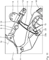
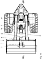
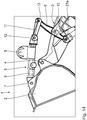
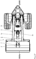
- FIGS Figures 1 to 8 An excavator bucket assembly 1 is shown in FIGS Figures 1 to 8 with an excavator bucket 2 in a bucket lifting position and a bucket arm 3 in a bucket arm lifting position.
- the excavator bucket 2 is connected to the bucket arm 3 via a bucket swivel joint with a joint axis 4.
- the hinge axis 4 runs horizontally.
- the blade arm 3 is, for example, from the Figure 1 evident, executed with two arms with two arms, which in the Figure 1 are designated 3a, 3b.
- a bucket swivel locking device 5 serves to lock or fix the excavator bucket 2 relative to the bucket arm 3.
- the latter has a bucket connecting lever 6 which is connected to the excavator bucket 2 via a bucket connecting joint with articulated axis 7.
- An actuating handle 8 for the excavator bucket assembly 1 is attached to the bucket connecting lever 6.
- the operating handle 8 is integrally formed on the blade connecting lever 6.
- the operating handle 8 is designed in such a way that both tensile and pressure forces can be exerted on the blade connecting lever 6.
- the bucket swivel locking device 5 has a bucket arm connecting lever 9.
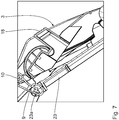
- the latter is connected to the bucket arm 3 via a bucket arm connecting joint with an articulated axis 10 (cf. Fig. 7 ) connected.
- a rocker link lever 11 also belongs to the bucket swivel locking device 5.
- the rocker link lever 11 is connected on the one hand to the bucket link lever 6 via a bucket-rocker link with articulated axis 12 and on the other hand to the bucket arm link lever 9 via a bucket arm.
- Rocker connection joint connected to joint axis 13.
- the hinge axes 7, 12 and 13 run parallel and spaced apart.
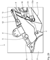
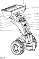
- the bucket connecting joint 7 and the two rocker connecting joints 12, 13 are arranged relative to one another such that the rocker connecting lever has a dead center position at which the bucket arm-rocker connecting joint 13 passes through a dead center joint plane 14 between the in the Figures 1 to 8 shown bucket lifting position and one in the Figures 12 to 14 and for example in the Figures 27 to 29 Shovel delivery position shown is shiftable.
- the dead center joint plane 14 is indicated by the joint axes 7, 12 on the one hand of the blade connecting joint and on the other hand the blade-rocker connecting joint.
- the bucket dead center position is in the Figures 9 to 11 shown. In this dead center position, the hinge axis of the bucket arm-rocker connection joint 13 lies in the dead center joint plane 14.
- the excavator bucket 2 In the bucket raised position, the excavator bucket 2 is in a raised raised pivot position relative to the bucket arm 3. In the bucket delivery position, the excavator bucket 2 lies relative to the bucket arm 3 in a delivery pivot position pivoted downward relative to the bucket lifting position.
- the bucket release position can be reached under the dead weight of the excavator bucket 2, starting from the bucket lifting position.
- the dead center of the rocker connecting lever 11 is overcome, starting from the bucket lifting position, by pulling on the actuating handle 8, so that the bucket connecting lever 6 pivots about the bucket connecting joint 7, starting from the locking position of the bucket swivel locking device 5, for example after Figure 4 the dead center is reached, for example in the Figure 11 is reached.
- the shovel delivery position is determined, for example, according to Figures 12 to 14 reached.
- the bucket arm 3 is connected to the frame component 16 via a bucket arm swivel joint with articulated axis 17.
- An excavation component 15 also includes an actuation component 18, which is designed as an actuation button.
- the actuating component 18 can be displaced relative to the bucket arm 3 in a guided manner, for example in the Figure 7 locking position shown and one example in the Figure 17 shown trigger position.
- a locking element 19 interacts with a stop 20 of the bucket arm 3 for holding the bucket arm 3 in the bucket arm lifting position (cf. Fig. 8 ).
- the locking element 19 is designed in the form of a stylized piston.
- the locking element 19 is connected to the frame component 16 via a locking connecting joint with the joint axis 19a. As with the bucket arm 3, the locking element 19 is also double.
- the locking element 19 is out of engagement with the stop 20 of the bucket arm 3, so that the bucket arm 3 can be displaced into the bucket arm lowering position.
- actuating component 18 is biased in the locking position.
- the excavator structure 15 is part of a toy, in particular a toy vehicle, which can be designed as an excavator.
- the excavator bucket assembly 1, the excavator assembly 15 and the entire toy can be made of plastic.
- the individual components can be manufactured as injection molded parts.
- the operator can switch between the different bucket positions and the different bucket arm positions, which are shown in the figures, with the aid of the actuating handle 8 on the one hand and the actuating component 18 on the other hand. Because of the bucket swivel locking device 5, the excavator bucket 2 remains fixed in the bucket lifting position, regardless of the bucket arm position, provided that the operator does not actively change the bucket.
- the bucket arm connecting lever 9 functions as part of a parallelogram guide, which ensures that when the bucket arm 3 moves between the lifting and lowering positions, the bucket arm 3 remains in the bucket lifting position with the correct angle so it doesn't become an unwanted Emptying the excavator shovel 2 comes.
- Part of this parallelogram guide is a coupling rod 23.
- the coupling rod 23 is connected to the bucket arm connecting lever 9 via a connecting coupling joint with a joint axis 23a.
- the coupling rod 23 is connected to the frame component 16 of the excavator structure 15 via a further bucket arm coupling joint.
- the bucket arm 3 remains, for example, in the bucket arm lifting position 3 when the excavator bucket 2 is changed. If the excavator bucket 2 is moved from the bucket lifting position to the bucket delivery position when the bucket arm 3 is lowered, this leads to the height of the ground, on which a lower edge 2a of the excavator shovel 2 comes to rest, possibly for lifting the shovel arm 3 from that in, for example, FIG Figure 22
- Shovel arm lower position shown in an intermediate shovel arm position ie in a pivoting position of the shovel arm 3 between the shovel arm lower position and the shovel arm raised position.
- Such an intermediate position is for example in the Figure 28 shown.
- the rocker connection lever 11 is around the bucket-rocker connection joint 12 in comparison to the bucket lifting position, for example Figure 4 pivoted by about 180 °, so that the blade connecting lever 6 and the rocker connecting lever 11 are now in a relative position arranged stretched relative to one another and between the blade connecting joint 7 on the one hand and the On the other hand, there is a large distance between the bucket arm-rocker connection joint 13.
- This large distance between the joints 7, 13 allows the excavator bucket 2 to pivot relative to the bucket arm 3 about the bucket swivel joint 4 downward, for example a comparison of the Figures 3 and 13 shows.
Landscapes
- Toys (AREA)
- Shovels (AREA)
Abstract
Description
- Die vorliegende Patentanmeldung nimmt die Priorität der deutschen Patentanmeldung
DE 10 2019 201 054.7 in Anspruch, deren Inhalt durch Bezugnahme hierin aufgenommen wird. - Die Erfindung betrifft eine Baggerschaufel-Baugruppe mit einer Baggerschaufel und einem hiermit über ein Schaufel-Schwenkgelenk verbunden Schaufelarm. Ferner betrifft die Erfindung einen Bagger-Aufbau für ein Spielzeug mit einer derartigen Baggerschaufel-Baugruppe sowie ein Spielzeug mit einem derartigen Bagger-Aufbau.
- Spielzeuge mit Bagger-Aufbauten sind bekannt beispielsweise aus der
EP 1 121 965 B1 , derEP 1 693 093 B1 undEP 3 047 887 B1 . - Es ist eine Aufgabe der vorliegenden Erfindung, verschiedene Grundpositionen der Baggerschaufel sicher, dabei aber gleichzeitig einfach wechselbar zu fixieren, um somit das Spielerlebnis zu steigern.
- Diese Aufgabe ist erfindungsgemäß gelöst durch eine Baggerschaufel-Baugruppe mit dem im Anspruch 1 angegebenen Merkmalen.
- Eine Schaufel-Schwenkarretierungs-Einrichtung mit einem Wipp-Verbindungshebel, der eine Totpunktstellung überwinden kann, stellt eine einerseits hinreichend sichere und andererseits hinreichend einfach überwindbare Gestaltung zur Vorgabe verschiedener Grundpositionen der Baggerschaufel relativ zum Schaufelarm dar.
- Die Abgabe-Schwenkstellung der Baggerschaufel kann nach Überwindung des Totpunktes des Wipp-Verbindungshebels unter einem Eigengewicht der Baggerschaufel erreicht werden.
- Ein Betätigungsgriff nach Anspruch 2 erleichtert eine Handhabung der Schaufel-Schwenkarretierungs-Einrichtung. Der Betätigungsgriff kann an dem Schaufel-Verbindungshebel insbesondere einstückig angeformt sein. Der Betätigungsgriff kann so angeordnet sein, dass eine EinhandBedienung der Schaufel-Schwenkarretierungs-Einrichtung möglich ist. Der Betätigungsgriff kann so angeordnet sein, dass er in gleicher Weise für Rechtshänder und für Linkshänder bedienbar ist.
- Eine Gestaltung des Betätigungsgriffs nach Anspruch 3 führt zu einer weiteren Erleichterung einer Bedienung der Schaufel-Schwenkarretierungs-Einrichtung.
- Die Vorteile eines Bagger-Aufbaus nach Anspruch 4 entsprechen denen, die vorstehend unter Bezugnahme auf die Baggerschaufel-Baugruppe bereits erläutert wurden. Die Schaufelarm-Absenkstellung kann nach Umstellung der Betätigungskomponente in die Auslösestellung, unter einem Eigengewicht des Schaufelarms erreicht werden. Die Betätigungskomponente kann als Betätigungsknopf ausgeführt sein.
- Eine Vorspannung der Betätigungskomponente nach Anspruch 5 sorgt für eine sichere und reproduzierbare Positionierung der Betätigungskomponente. Die Vorspannung kann über eine Federkomponente geschehen, die beispielsweise am Schaufelarm befestigt ist und die insbesondere integraler beziehungsweise einstückiger Bestandteil des Schaufelarms sein kann.
- Eine Gelenkverbindung zwischen dem Riegelelement und der Rahmenkomponente nach Anspruch 6 führt zu einer Annäherung einer Kinematik des Bagger-Aufbaus bei der Bewegung des Schaufelarms an ein reales Bagger-Vorbild.
- Die Vorteile eines Spielzeugs nach Anspruch 7 entsprechen denen, die vorstehend in Zusammenhang mit dem Bagger-Aufbau und der Baggerschaufel bereits erläutert wurden. Bei dem Spielzeug kann es sich um ein Spielfahrzeug handeln. Das Spielzeug kann insbesondere insgesamt aus Kunststoff hergestellt sein. Bei einigen oder allen Komponenten des Spielzeugs kann es sich um Spritzguss-Bauteile handeln.
- Ein Ausführungsbeispiel der Erfindung wird nachfolgend anhand der Zeichnungen näher erläutert. In dieser zeigen:
- Fig. 1
- eine Aufsicht auf einen vorderen Abschnitt eines Bagger-Spielfahrzeugs mit einem Bagger-Aufbau, aufweisend eine Baggerschaufel-Baugruppe, wobei eine Baggerschaufel der Baugruppe in einer Schaufel-Anhebestellung und ein Schau-felarm der Baugruppe in einer Schaufelarm-Anhebestellung vorliegt;
- Fig. 2
- eine Seitenansicht des Fahrzeug-Abschnitts nach
Figur 1 , gesehen aus Blickrichtung II inFigur 1 ; - Fig. 3
- einen Schnitt gemäß Linie III-III in
Figur 1 ; - Fig. 4
- ein Detail IV aus
Figur 3 ; - Fig. 5
- einen Schnitt gemäß Linie V-V in
Figur 1 ; - Fig. 6
- eine Unteransicht eines Details des Fahrzeug-Abschnitts gemäß Linie VI in
Figur 5 ; - Fig. 7
- ein Detail VII aus
Figur 5 ; - Fig. 8
- ein Detail VIII aus
Figur 3 ; - Fig. 9
- in einer zu
Figur 1 ähnlichen Ansicht den Fahrzeug-Abschnitt, wobei die Baggerschaufel in einer Schaufel-Totpunktstellung einer Schaufel-Schwenkarretierungs-Einrichtung und der Schaufelarm weiterhin in der Schaufelarm-Anhebestellung vorliegt; - Fig. 10
- einen Schnitt gemäß Linie X-X in
Figur 9 ; - Fig. 11
- ein Detail XI aus
Figur 10 ; - Fig. 12
- in einer zu
Figur 1 ähnlichen Ansicht den Fahrzeug-Abschnitt mit der Baggerschaufel in einer Schaufel-Abgabestellung und dem Schaufelarm weiterhin in der Schaufelarm-Anhebestellung; - Fig. 13
- einen Schnitt gemäß Linie XIII-XIII in
Figur 12 ; - Fig. 14
- ein Detail XIV aus
Figur 13 ; - Fig. 15
- in einer zu
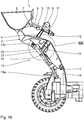
Figur 1 ähnlichen Ansicht den Fahrzeug-Abschnitt mit der Baggerschaufel in der Schaufel-Anhebestellung und einen Betätigungsgriff in einer Auslösestellung, in der der Schaufelarm in eine Schaufelarm-Absenkstellung verlagerbar ist; - Fig. 16
- einen Schnitt gemäß Linie XVI-XVI in
Figur 15 ; - Fig. 17
- ein Detail XVII aus
Figur 16 ; - Fig. 18
- einen Schnitt XVIII-XVIII in
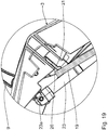
Figur 15 ; - Fig. 19
- ein Detail XIX aus
Figur 18 ; - Fig. 20
- in einer zu
Figur 1 ähnlichen Ansicht den Fahrzeug-Abschnitt mit der Baggerschaufel weiterhin in der SchaufelAnhebestellung und dem Schaufelarm in einer SchaufelarmAbsenkstellung; - Fig. 21
- eine Seitenansicht des Fahrzeug-Abschnitts, gesehen aus Blickrichtung XXI in
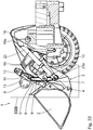
Figur 20 ; - Fig. 22
- einen Schnitt gemäß Linie XXII-XXII in
Figur 20 ; - Fig. 23
- ein Detail XXIII aus
Figur 22 ; - Fig. 24
- in einer zu
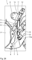
Figur 1 ähnlichen Ansicht den Fahrzeug-Abschnitt mit dem Schaufelarm in der Schaufelarm-Absenkstellung und der Schaufel-Schwenkarretierungs-Einrichtung in der Schaufel-Totpunkt-Stellung; - Fig. 25
- einen Schnitt gemäß Linie XXV-XXV in
Figur 24 ; - Fig. 26
- ein Detail XXVI in
Figur 25 ; - Fig. 27
- in einer zu
Figur 1 ähnlichen Darstellung den FahrzeugAbschnitt mit der Baggerschaufel weiterhin in der SchaufelAbgabestellung, wobei der Schaufelarm in eine Stellung nahe der Schaufelarm-Absenkstellung bis zum Bodenkontakt der Baggerschaufel abgesenkt ist; - Fig. 28
- ein Schnitt gemäß Linie XXVIII-XXVIII in
Figur 27 ; - Fig. 29
- ein Detail XXIX aus
Figur 28 ; und - Fig. 30
- eine perspektivische Darstellung des Fahrzeug-Abschnitts in der Stellung der Baggerschaufel und des Schaufelarms nach den
Figuren 27 bis 29 . - Eine Baggerschaufel-Baugruppe 1 ist in den
Figuren 1 bis 8 mit einer Baggerschaufel 2 in einer Schaufel-Anhebestellung und ein Schaufelarm 3 in einer Schaufelarm-Anhebestellung dargestellt. Die Baggerschaufel 2 ist mit dem Schaufelarm 3 über ein Schaufel-Schwenkgelenk mit Gelenkachse 4 verbunden. Die Gelenkachse 4 verläuft horizontal. Der Schaufelarm 3 ist, wie beispielsweise aus derFigur 1 ersichtlich, doppelarmig mit zwei Teilarmen ausgeführt, die in derFigur 1 mit 3a, 3b bezeichnet sind. - Zur Arretierung beziehungsweise Positionsfixierung der Baggerschaufel 2 relativ zum Schaufelarm 3 dient eine Schaufel-SchwenkarretierungsEinrichtung 5. Letztere hat einen Schaufel-Verbindungshebel 6, der mit der Baggerschaufel 2 über ein Schaufel-Verbindungsgelenk mit Gelenkachse 7 verbunden ist. Am Schaufel-Verbindungshebel 6 ist ein Betätigungsgriff 8 für die Baggerschaufel-Baugruppe 1 befestigt. Der Betätigungsgriff 8 ist einstückig an den Schaufel-Verbindungshebel 6 angeformt. Der Betätigungsgriff 8 ist so gestaltet, dass über diesen sowohl Zug- als auch Drucckräfte auf den Schaufel-Verbindungshebel 6 ausgeübt werden können.
- Weiterhin hat die Schaufel-Schwenkarretierungs-Einrichtung 5 einen Schaufelarm-Verbindungshebel 9. Letzterer ist mit dem Schaufelarm 3 über ein Schaufelarm-Verbindungsgelenk mit einer Gelenkachse 10 (vgl.
Fig. 7 ) verbunden. - Zur Schaufel-Schwenkarretierungs-Einrichtung 5 gehört weiterhin ein Wipp-Verbindungshebel 11. Der Wipp-Verbindungshebel 11 ist einerseits mit dem Schaufel-Verbindungshebel 6 über ein Schaufel-Wipp-Verbindungsgelenk mit Gelenkachse 12 und andererseits mit dem Schaufelarm-Verbindungshebel 9 über ein Schaufelarm-Wipp-Verbindungsgelenk mit Gelenkachse 13 verbunden.
- Die Gelenkachsen 7, 12 und 13 verlaufen parallel und beabstandet zueinander.
- Das Schaufel-Verbindungsgelenk 7 und die beiden Wipp-Verbindungsgelenke 12, 13 sind so zueinander angeordnet, dass der Wipp-Verbindungshebel über eine Totpunktstellung, bei der das Schaufelarm-Wipp-Verbindungsgelenk 13 eine Totpunkt-Gelenkebene 14 durchtritt, zwischen der in den
Figuren 1 bis 8 dargestellten Schaufel-Anhebestellung und einer in denFiguren 12 bis 14 und beispielsweise auch in denFiguren 27 bis 29 dargestellten Schaufel-Abgabestellung verlagerbar ist. - Die Totpunkt-Gelenkebene 14 ist durch die Gelenkachsen 7, 12 einerseits des Schaufel-Verbindungsgelenks und andererseits das Schaufel-Wipp-Verbindungsgelenks angegeben.
- In der Stellung beispielsweise nach den
Figuren 3 und4 liegt die Gelenkachse 13 des Schaufelarm-Wipp-Verbindungsgelenks beabstandet zur Totpunkt-Gelenkebene 14. - Die Schaufel-Totpunktstellung ist in den
Figuren 9 bis 11 gezeigt. In dieser Totpunktstellung liegt die Gelenkachse des Schaufelarm-Wipp-Verbindungsgelenks 13 in der Totpunkt-Gelenkebene 14. - In der Schaufel-Anhebestellung liegt die Baggerschaufel 2 relativ zum Schaufelarm 3 in einer angehobenen Anhebe-Schwenkstellung. In der Schaufel-Abgabestellung liegt die Baggerschaufel 2 relativ zum Schaufelarm 3 in einer relativ zur Schaufel-Anhebestellung nach unten verschwenkten Abgabe-Schwenkstellung.
- Nach Überwindung der Schaufel-Totpunktstellung kann, ausgehend von der Schaufel-Anhebestellung, die Schaufel-Abgabestellung unter dem Eigengewicht der Baggerschaufel 2 erreicht werden. Der Totpunkt des Wipp-Verbindungshebels 11 wird, ausgehend von der Schaufel-Anhebestellung, überwunden, indem am Betätigungsgriff 8 gezogen wird, sodass der Schaufel-Verbindungshebel 6 um das Schaufel-Verbindungsgelenk 7 verschwenkt, bis ausgehend von der Arretierstellung der Schaufel-Schwenkarretierungs-Einrichtung 5, beispielsweise nach
Figur 4 der Totpunkt erreicht ist, der beispielsweise in derFigur 11 erreicht ist. Anschließend wird unter dem Eigengewicht der Baggerschaufel 2 die Schaufel-Abgabestellung beispielsweise nach denFiguren 12 bis 14 erreicht. - Zu einem Bagger-Aufbau 15, von dem die Baggerschaufel-Baugruppe 1 einen Teil darstellt, gehört zudem eine Rahmenkomponente 16, die Bestandteil eines Rahmes des Bagger-Aufbaus 15 ist. Der Schaufelarm 3 ist der Rahmenkomponente 16 über ein Schaufelarm-Schwenkgelenk mit Gelenkachse 17 verbunden.
- Zum Bagger-Aufbau 15 gehört weiterhin eine Betätigungskomponente 18, die als Betätigungsknopf ausgeführt ist. Die Betätigungskomponente 18 ist relativ zum Schaufelarm 3 geführt verlagerbar zwischen einer beispielsweise in der
Figur 7 dargestellten Verriegelungsstellung und einer beispielsweise in derFigur 17 dargestellten Auslösestellung. In der Verriegelungsstellung wirkt ein Riegelelement 19 mit einem Anschlag 20 des Schaufelarms 3 zum Halten des Schaufelarms 3 in der Schaufelarm-Anhebestellung zusammen (vgl.Fig. 8 ). - Das Riegelelement 19 ist in der Form eines stilisierten Kolbens ausgebildet. Das Riegelelement 19 ist mit der Rahmenkomponente 16 über ein Riegel-Verbindungsgelenk mit Gelenkachse 19a verbunden. Wie beim Schaufelarm 3 ist auch das Riegelelement 19 doppelt ausgeführt vorhanden.
- In der Verriegelungsstellung wirkt eine Stirnfläche des Riegelelements 19 mit dem Anschlag 20 des Schaufelarms 3 zusammen. In der Verriegelungsstellung liegt ein Abschnitt 21 der Betätigungskomponente 18 an einer Mantelwand des Riegelelements 19 an (vgl.
Fig. 8 ). - In der Auslösestellung der Betätigungskomponente 18 (vgl.
Figur 19 ) ist auch der am Riegelelement 19 anliegende Abschnitt 21 der Betätigungskomponente 18 mitverlagert und drückt, wie durch Vergleich derFiguren 8 und19 ersichtlich ist, das Riegelelement 19 vom Anschlag 20 weg, sodass das Riegelelement 19 vom Schaufelarm 3 freikommt. - Das Riegelelement 19 ist in der Auslösestellung außer Eingriff mit dem Anschlag 20 des Schaufelarms 3, sodass der Schaufelarm 3 in die Schaufelarm-Absenkstellung verlagerbar ist.
- Über eine als Federzunge ausgeführte Federkomponente 22 (vgl.
Fig. 6 ) ist die Betätigungskomponente 18 in der Verriegelungsstellung vorgespannt. - Der Bagger-Aufbau 15 ist Bestandteil eines Spielzeugs, insbesondere eines Spielfahrzeugs, welches insgesamt als Bagger ausgeführt sein kann.
- Die Baggerschaufel-Baugruppe 1, der Bagger-Aufbau 15 sowie das gesamte Spielzeug können aus Kunststoff gefertigt sein. Die einzelnen Bestandteile können als Spritzgussteile gefertigt sein.
- Beim Spielen mit einem Spielzeug, welches den Bagger-Aufbau 15 aufweist, kann die Bedienperson mit Hilfe einerseits des Betätigungsgriffs 8 und andererseits der Betätigungskomponente 18 zwischen den verschiedenen Schaufelstellungen und den verschiedenen Schaufelarmstellungen wechseln, die in Figuren dargestellt sind. Aufgrund der Schaufel-Schwenkarretierungs-Einrichtung 5 bleibt die Baggerschaufel 2 unabhängig von der Schaufelarmstellung in der Schaufel-Anhebestellung fixiert, sofern nicht von der Bedienperson eine aktive Umstellung der Schaufel herbeigeführt wird.
- Bei in der Schaufel-Anhebestellung fixierter Baggerschaufel 2 fungiert der Schaufelarm-Verbindungshebel 9 als Teil einer Parallelogramm-Führung, die dafür sorgt, dass die Baggerschaufel 2 bei einer Bewegung des Schaufelarms 3 zwischen der Anhebe- und der Absenkstellung winkelrichtig in der Schaufel-Anhebestellung verbleibt, sodass es nicht zu einem unerwünschten Entleeren der Baggerschaufel 2 kommt. Teil dieser Parallelogramm-Führung ist eine Koppelstange 23. Die Koppelstange 23 ist mit dem Schaufelarm-Verbindungshebel 9 über ein Verbindungs-Koppel-Gelenk mit Gelenkachse 23a verbunden. Die Koppelstange 23 ist mit der Rahmenkomponente 16 des Bagger-Aufbaus 15 über ein weiteres Schaufelarm-Koppel-Gelenk verbunden. Diese Funktion der Parallelogramm-Führung, zu der neben dem Schaufelarm-Verbindungshebel 9 und auch die weiteren Hebel der Schaufel-Schwenkarretierungseinrichtung gehören, ergibt sich anschaulich durch Vergleich beispielsweise der
Figuren 3 und22 . - Genauso bleibt der Schaufelarm 3 zum Beispiel in der Schaufelarm-Anhebestellung 3 bei einer Umstellung der Baggerschaufel 2. Wenn die Baggerschaufel 2 von der Schaufel-Anhebestellung in die Schaufel-Abgabestellung bei abgesenktem Schaufelarm 3 verstellt wird, führt dies abhängig von der Höhe des Untergrundes, auf dem eine Unterkante 2a der Baggerschaufel 2 zu liegen kommt, gegebenenfalls zu einem Anheben des Schaufelarms 3 von der beispielsweise in der
Figur 22 dargestellten Schaufelarm-Absenkstellung in eine Schaufelarm-Zwischenstellung, also in eine Schwenkposition des Schaufelarms 3 zwischen der Schaufelarm-Absenkstellung und der Schaufelarm-Anhebestellung. Eine derartige Zwischenstellung ist beispielsweise in derFigur 28 dargestellt. - In der Schaufel-Abgabestellung ist der Wipp-Verbindungshebel 11 um das Schaufel-Wipp-Verbindungsgelenk 12 im Vergleich zur Schaufel-Anhebestellung beispielsweise nach
Figur 4 um etwa 180° verschwenkt, sodass der Schaufel-Verbindungshebel 6 und der Wipp-Verbindungshebel 11 nun in einer zueinander gestreckt angeordneten Relativposition vorliegen und zwischen dem Schaufel-Verbindungsgelenk 7 einerseits und dem Schaufelarm-Wipp-Verbindungsgelenk 13 andererseits ein großer Abstand vorliegt. Dieser große Abstand zwischen den Gelenken 7, 13 ermöglicht ein Verschwenken der Baggerschaufel 2 relativ zum Schaufelarm 3 um das Schaufel-Schwenkgelenk 4 nach unten, wie beispielsweise ein Vergleich derFiguren 3 und13 zeigt.
Claims (7)
- Baggerschaufel-Baugruppe (1)- mit einer Baggerschaufel (2),- mit einem Schaufelarm (3), mit dem die Baggerschaufel (2) über ein Schaufel-Schwenkgelenk (4) verbunden ist,- mit einer Schaufel-Schwenkarretierungs-Einrichtung (5) zur Arretierung der Baggerschaufel (2) relativ zum Schaufelarm (3),- wobei die Schaufel-Schwenkarretierungs-Einrichtung (5) aufweist:-- einen Schaufel-Verbindungshebel (6), der mit der Baggerschaufel (2) über ein Schaufel-Verbindungsgelenk (7) verbunden ist,-- einen Schaufelarm-Verbindungshebel (9), der mit dem Schaufelarm (3) über ein Schaufelarm-Verbindungsgelenk (10) verbunden ist,-- einen Wipp-Verbindungshebel (11), der einerseits mit dem Schaufel-Verbindungshebel (6) über ein Schaufel-Wipp-Verbindungsgelenk (12) und andererseits mit dem Schaufelarm-Verbindunghebel (9) über ein Schaufelarm-Wipp-Verbindungsgelenk (13) verbunden ist,- wobei das Schaufel-Verbindungsgelenk (7) und die beiden Wipp-Verbindungsgelenke (12, 13) so angeordnet sind, dass der Wipp-Verbindungshebel (11) über eine Totpunktstellung, bei der eines der Wipp-Verbindungsgelenke (13) eine Totpunkt-Gelenkebene (14) durchtritt, die über das Schaufel-Verbindungsgelenk (7) und das andere der beiden Wipp-Verbindungsgelenke (12) vorgegeben ist, verlagerbar ist zwischen-- einer Schaufel-Anhebestellung, in der die Baggerschaufel (2) relativ zum Schaufelarm (3) in einer angehobenen Anhebe-Schwenkstellung liegt,-- einer Schaufel-Abgabestellung, in der die Baggerschaufel (2) relativ zum Schaufelarm (3) in einer im Vergleich zur Schaufel-Anhebestellung nach unten verschwenkten Abgabe-Schwenkstellung liegt.
- Baggerschaufel-Baugruppe nach Anspruch 1, gekennzeichnet durch einen Betätigungsgriff (8), der am Schaufel-Verbindungshebel (6) befestigt ist.
- Baggerschaufel-Baugruppe nach Anspruch 2, gekennzeichnet durch eine Gestaltung des Betätigungsgriffs (8) derart, dass über diesen Zug- und Druckkräfte auf den Schaufel-Verbindungshebel (6) ausgeübt werden können.
- Bagger-Aufbau (15) für ein Spielzeug,- mit einer Baggerschaufel-Baugruppe nach einem der Ansprüche 1 bis 3,- mit einer Rahmenkomponente (16),- mit einer Betätigungskomponente (18), die relativ zum Schaufelarm (3) geführt verlagerbar ist zwischen-- einer Verriegelungsstellung, in der ein Riegelelement (19), das mit der Rahmenkomponente (16) verbunden ist, mit einem Anschlag (20) des Schaufelarms (3) zum Halten des Schaufelarms (3) in einer Schaufelarm-Anhebestellung zusammenwirkt, und-- einer Auslösestellung, in der die Betätigungskomponente (18) das Riegelelement (19) so verlagert, dass dieses außer Eingriff mit dem Anschlag (20) des Schaufelarms (3) kommt, sodass der Schaufelarm (3) in eine Schaufelarm-Absenkstellung verlagerbar ist.
- Bagger-Aufbau nach Anspruch 4, dadurch gekennzeichnet, dass die Betätigungskomponente (18) in der Verriegelungsstellung vorgespannt ist.
- Bagger-Aufbau nach Anspruch 4 oder 5, dadurch gekennzeichnet, dass das Riegelelement (19) mit der Rahmenkomponente (16) über ein Riegel-Verbindungsgelenk (19a) verbunden ist.
- Spielzeug mit einem Bagger-Aufbau (15) nach einem der Ansprüche 4 bis 6.
Priority Applications (1)
| Application Number | Priority Date | Filing Date | Title |
|---|---|---|---|
| PL19215864T PL3685896T3 (pl) | 2019-01-28 | 2019-12-13 | Zespół szufli koparki |
Applications Claiming Priority (1)
| Application Number | Priority Date | Filing Date | Title |
|---|---|---|---|
| DE102019201054.7A DE102019201054B3 (de) | 2019-01-28 | 2019-01-28 | Baggerschaufel-Baugruppe |
Publications (3)
| Publication Number | Publication Date |
|---|---|
| EP3685896A2 true EP3685896A2 (de) | 2020-07-29 |
| EP3685896A3 EP3685896A3 (de) | 2020-08-12 |
| EP3685896B1 EP3685896B1 (de) | 2021-04-07 |
Family
ID=68916294
Family Applications (1)
| Application Number | Title | Priority Date | Filing Date |
|---|---|---|---|
| EP19215864.0A Active EP3685896B1 (de) | 2019-01-28 | 2019-12-13 | Baggerschaufel-baugruppe |
Country Status (4)
| Country | Link |
|---|---|
| US (1) | US11135524B2 (de) |
| EP (1) | EP3685896B1 (de) |
| DE (1) | DE102019201054B3 (de) |
| PL (1) | PL3685896T3 (de) |
Families Citing this family (1)
| Publication number | Priority date | Publication date | Assignee | Title |
|---|---|---|---|---|
| DE102020216589A1 (de) * | 2020-12-30 | 2022-06-30 | Bruder Spielwaren Gmbh + Co. Kg | Spielfahrzeug |
Citations (3)
| Publication number | Priority date | Publication date | Assignee | Title |
|---|---|---|---|---|
| EP1121965B1 (de) | 2000-02-02 | 2004-09-08 | Bruder Spielwaren GmbH + Co. KG | Spielzeugfahrzeug nach Art eines Baggerladers |
| EP1693093B1 (de) | 2005-02-05 | 2008-03-12 | Bruder Spielwaren GmbH + Co. KG | Spielfahrzeug-Ladearm für schwenkbare Ladeschaufel |
| EP3047887B1 (de) | 2015-01-21 | 2018-07-18 | Bruder Spielwaren GmbH + Co. KG | Spielfahrzeug-bagger |
Family Cites Families (16)
| Publication number | Priority date | Publication date | Assignee | Title |
|---|---|---|---|---|
| US2563974A (en) * | 1946-06-21 | 1951-08-14 | John A Thierry | Toy excavator |
| US2812869A (en) * | 1954-11-17 | 1957-11-12 | Marx & Co Louis | Toy power shovel |
| US2896802A (en) * | 1958-03-31 | 1959-07-28 | Hope Norris | Toy |
| US2985983A (en) * | 1959-05-01 | 1961-05-30 | Wilbert P Konstenius | Toy power shovel |
| US3161987A (en) * | 1963-01-16 | 1964-12-22 | Structo Mfg Company | Bulldozer toy with automatic dump mechanism |
| US3462874A (en) * | 1968-01-17 | 1969-08-26 | Tonka Corp | Toy loader |
| US3539063A (en) * | 1968-07-03 | 1970-11-10 | Emil S Masura | Toy simulating a boom carrying machine |
| US3624957A (en) * | 1969-05-26 | 1971-12-07 | Tonka Corp | Scoop shovel for toy vehicles |
| US3744181A (en) * | 1972-08-15 | 1973-07-10 | R Gagnon | Toy front loader with caterpillar drive |
| CA1265338A (en) * | 1984-11-13 | 1990-02-06 | George C. Manning | Mechanical digger toy |
| DE29800336U1 (de) * | 1998-01-10 | 1998-03-19 | Bruder Spielwaren GmbH & Co. KG, 90768 Fürth | Spielzeugfahrzeug mit einer Ladeschaufel |
| US6508320B2 (en) * | 2001-02-08 | 2003-01-21 | Mattel, Inc. | Children's ride-on vehicle and bucket assembly |
| DE102004042646B3 (de) * | 2004-09-03 | 2006-03-09 | Franz Schneider Gmbh & Co Kg | Kinderspielfahrzeug |
| EP1955747B1 (de) * | 2007-02-08 | 2009-07-22 | Franz Schneider GmbH & Co. KG | Kinderspielzeug, insbesondere Kinderfahrzeug mit Ladeschaufel |
| DE202008003709U1 (de) * | 2008-03-15 | 2008-07-03 | Bruder Spielwaren Gmbh + Co. Kg | Spielzeugfahrzeug |
| DE102015000666B4 (de) * | 2015-01-23 | 2022-07-07 | Franz Schneider Gmbh & Co. Kg | Spielfahrzeug - Bagger |
-
2019
- 2019-01-28 DE DE102019201054.7A patent/DE102019201054B3/de not_active Expired - Fee Related
- 2019-12-13 EP EP19215864.0A patent/EP3685896B1/de active Active
- 2019-12-13 PL PL19215864T patent/PL3685896T3/pl unknown
-
2020
- 2020-01-27 US US16/752,927 patent/US11135524B2/en active Active
Patent Citations (3)
| Publication number | Priority date | Publication date | Assignee | Title |
|---|---|---|---|---|
| EP1121965B1 (de) | 2000-02-02 | 2004-09-08 | Bruder Spielwaren GmbH + Co. KG | Spielzeugfahrzeug nach Art eines Baggerladers |
| EP1693093B1 (de) | 2005-02-05 | 2008-03-12 | Bruder Spielwaren GmbH + Co. KG | Spielfahrzeug-Ladearm für schwenkbare Ladeschaufel |
| EP3047887B1 (de) | 2015-01-21 | 2018-07-18 | Bruder Spielwaren GmbH + Co. KG | Spielfahrzeug-bagger |
Also Published As
| Publication number | Publication date |
|---|---|
| PL3685896T3 (pl) | 2021-10-18 |
| EP3685896A3 (de) | 2020-08-12 |
| US20200238187A1 (en) | 2020-07-30 |
| EP3685896B1 (de) | 2021-04-07 |
| US11135524B2 (en) | 2021-10-05 |
| DE102019201054B3 (de) | 2020-02-13 |
Similar Documents
| Publication | Publication Date | Title |
|---|---|---|
| EP3423313B1 (de) | Klappenscharnier für eine frontklappe eines fahrzeugs mit einer verschiebbaren lagerung eines hubaktuators | |
| DE4242895C1 (de) | Verriegelung für eine Längsverstellung eines Sitzes | |
| EP1989082B1 (de) | Karosserie für ein kraftfahrzeug | |
| EP0437711B1 (de) | Sicherungsvorrichtung für Schwenkbauteile von Fahrzeugen, insbesondere für Motorhauben von Kraftwagen | |
| DE2533337C3 (de) | Auslöseskibindung | |
| DE2237301C3 (de) | Längeneinstellvorrichtung zum selbsttätigen Einstellen eines Kabelzuges, insbesondere in Kraftfahrzeugen | |
| EP3685896B1 (de) | Baggerschaufel-baugruppe | |
| DE102019101919A1 (de) | Flurförderzeug mit einem schwenkbaren Dreieckhebel | |
| EP3423314A1 (de) | Klappenscharnier für eine frontklappe eines fahrzeugs mit einem teleskopierbaren lenkerhebel | |
| EP0941888B1 (de) | Längsverstellvorrichtung für einen Sitz, insbesondere Kraftfahrzeugsitz | |
| DE19809415A1 (de) | Verriegelungsvorrichtung für eine Klappe, insbesondere eine Kraftfahrzeug-Motorhaube | |
| DE19833402C2 (de) | Schalensitz für Fahrzeuge | |
| WO2014068127A1 (de) | Bodenbearbeitungsvorrichtung zum erzeugen von hohlräumen in einem boden | |
| AT382522B (de) | Fersenniederhalter | |
| CH623103A5 (en) | Setting-out device | |
| DE224558C (de) | ||
| DE102016204100B4 (de) | Verschlussvorrichtung für ein Cabriolet-Fahrzeug | |
| DE912227C (de) | Sicherungseinrichtung fuer Seilbahnkupplungen | |
| DE2440656C2 (de) | Ladewagen mit Heckklappe | |
| DE640818C (de) | Hebelgetriebe fuer drehende Fensterfluegel o. dgl. | |
| EP0683275A2 (de) | Betätigungseinrichtung für eine Ablaufarmatur eines Spülkastens | |
| DE864669C (de) | Tuerschloss, insbesondere fuer Kraftfahrzeuge | |
| DE102020109472A1 (de) | Kraftfahrzeugschloss | |
| DE2544443B2 (de) | Kraftfahrzeugturverschluß | |
| DE7410347U (de) | Schleppvorrichtung, vorzugsweise für einen Gabelhubwagen |
Legal Events
| Date | Code | Title | Description |
|---|---|---|---|
| PUAI | Public reference made under article 153(3) epc to a published international application that has entered the european phase |
Free format text: ORIGINAL CODE: 0009012 |
|
| STAA | Information on the status of an ep patent application or granted ep patent |
Free format text: STATUS: THE APPLICATION HAS BEEN PUBLISHED |
|
| REG | Reference to a national code |
Ref country code: DE Ref legal event code: R079 Ref document number: 502019001180 Country of ref document: DE Free format text: PREVIOUS MAIN CLASS: A63H0017050000 Ipc: A63H0017120000 |
|
| PUAL | Search report despatched |
Free format text: ORIGINAL CODE: 0009013 |
|
| AK | Designated contracting states |
Kind code of ref document: A2 Designated state(s): AL AT BE BG CH CY CZ DE DK EE ES FI FR GB GR HR HU IE IS IT LI LT LU LV MC MK MT NL NO PL PT RO RS SE SI SK SM TR |
|
| AX | Request for extension of the european patent |
Extension state: BA ME |
|
| STAA | Information on the status of an ep patent application or granted ep patent |
Free format text: STATUS: REQUEST FOR EXAMINATION WAS MADE |
|
| AK | Designated contracting states |
Kind code of ref document: A3 Designated state(s): AL AT BE BG CH CY CZ DE DK EE ES FI FR GB GR HR HU IE IS IT LI LT LU LV MC MK MT NL NO PL PT RO RS SE SI SK SM TR |
|
| AX | Request for extension of the european patent |
Extension state: BA ME |
|
| RIC1 | Information provided on ipc code assigned before grant |
Ipc: A63H 17/12 20060101AFI20200704BHEP |
|
| 17P | Request for examination filed |
Effective date: 20200724 |
|
| RBV | Designated contracting states (corrected) |
Designated state(s): AL AT BE BG CH CY CZ DE DK EE ES FI FR GB GR HR HU IE IS IT LI LT LU LV MC MK MT NL NO PL PT RO RS SE SI SK SM TR |
|
| GRAP | Despatch of communication of intention to grant a patent |
Free format text: ORIGINAL CODE: EPIDOSNIGR1 |
|
| STAA | Information on the status of an ep patent application or granted ep patent |
Free format text: STATUS: GRANT OF PATENT IS INTENDED |
|
| INTG | Intention to grant announced |
Effective date: 20201214 |
|
| GRAS | Grant fee paid |
Free format text: ORIGINAL CODE: EPIDOSNIGR3 |
|
| GRAA | (expected) grant |
Free format text: ORIGINAL CODE: 0009210 |
|
| STAA | Information on the status of an ep patent application or granted ep patent |
Free format text: STATUS: THE PATENT HAS BEEN GRANTED |
|
| AK | Designated contracting states |
Kind code of ref document: B1 Designated state(s): AL AT BE BG CH CY CZ DE DK EE ES FI FR GB GR HR HU IE IS IT LI LT LU LV MC MK MT NL NO PL PT RO RS SE SI SK SM TR |
|
| REG | Reference to a national code |
Ref country code: GB Ref legal event code: FG4D Free format text: NOT ENGLISH |
|
| REG | Reference to a national code |
Ref country code: CH Ref legal event code: EP Ref country code: AT Ref legal event code: REF Ref document number: 1378925 Country of ref document: AT Kind code of ref document: T Effective date: 20210415 |
|
| REG | Reference to a national code |
Ref country code: DE Ref legal event code: R096 Ref document number: 502019001180 Country of ref document: DE |
|
| REG | Reference to a national code |
Ref country code: NL Ref legal event code: FP |
|
| REG | Reference to a national code |
Ref country code: IE Ref legal event code: FG4D Free format text: LANGUAGE OF EP DOCUMENT: GERMAN |
|
| REG | Reference to a national code |
Ref country code: LT Ref legal event code: MG9D |
|
| PG25 | Lapsed in a contracting state [announced via postgrant information from national office to epo] |
Ref country code: HR Free format text: LAPSE BECAUSE OF FAILURE TO SUBMIT A TRANSLATION OF THE DESCRIPTION OR TO PAY THE FEE WITHIN THE PRESCRIBED TIME-LIMIT Effective date: 20210407 Ref country code: LT Free format text: LAPSE BECAUSE OF FAILURE TO SUBMIT A TRANSLATION OF THE DESCRIPTION OR TO PAY THE FEE WITHIN THE PRESCRIBED TIME-LIMIT Effective date: 20210407 Ref country code: FI Free format text: LAPSE BECAUSE OF FAILURE TO SUBMIT A TRANSLATION OF THE DESCRIPTION OR TO PAY THE FEE WITHIN THE PRESCRIBED TIME-LIMIT Effective date: 20210407 Ref country code: BG Free format text: LAPSE BECAUSE OF FAILURE TO SUBMIT A TRANSLATION OF THE DESCRIPTION OR TO PAY THE FEE WITHIN THE PRESCRIBED TIME-LIMIT Effective date: 20210707 |
|
| PG25 | Lapsed in a contracting state [announced via postgrant information from national office to epo] |
Ref country code: SE Free format text: LAPSE BECAUSE OF FAILURE TO SUBMIT A TRANSLATION OF THE DESCRIPTION OR TO PAY THE FEE WITHIN THE PRESCRIBED TIME-LIMIT Effective date: 20210407 Ref country code: PT Free format text: LAPSE BECAUSE OF FAILURE TO SUBMIT A TRANSLATION OF THE DESCRIPTION OR TO PAY THE FEE WITHIN THE PRESCRIBED TIME-LIMIT Effective date: 20210809 Ref country code: RS Free format text: LAPSE BECAUSE OF FAILURE TO SUBMIT A TRANSLATION OF THE DESCRIPTION OR TO PAY THE FEE WITHIN THE PRESCRIBED TIME-LIMIT Effective date: 20210407 Ref country code: LV Free format text: LAPSE BECAUSE OF FAILURE TO SUBMIT A TRANSLATION OF THE DESCRIPTION OR TO PAY THE FEE WITHIN THE PRESCRIBED TIME-LIMIT Effective date: 20210407 Ref country code: NO Free format text: LAPSE BECAUSE OF FAILURE TO SUBMIT A TRANSLATION OF THE DESCRIPTION OR TO PAY THE FEE WITHIN THE PRESCRIBED TIME-LIMIT Effective date: 20210707 Ref country code: GR Free format text: LAPSE BECAUSE OF FAILURE TO SUBMIT A TRANSLATION OF THE DESCRIPTION OR TO PAY THE FEE WITHIN THE PRESCRIBED TIME-LIMIT Effective date: 20210708 Ref country code: IS Free format text: LAPSE BECAUSE OF FAILURE TO SUBMIT A TRANSLATION OF THE DESCRIPTION OR TO PAY THE FEE WITHIN THE PRESCRIBED TIME-LIMIT Effective date: 20210807 |
|
| REG | Reference to a national code |
Ref country code: DE Ref legal event code: R097 Ref document number: 502019001180 Country of ref document: DE |
|
| PG25 | Lapsed in a contracting state [announced via postgrant information from national office to epo] |
Ref country code: SK Free format text: LAPSE BECAUSE OF FAILURE TO SUBMIT A TRANSLATION OF THE DESCRIPTION OR TO PAY THE FEE WITHIN THE PRESCRIBED TIME-LIMIT Effective date: 20210407 Ref country code: ES Free format text: LAPSE BECAUSE OF FAILURE TO SUBMIT A TRANSLATION OF THE DESCRIPTION OR TO PAY THE FEE WITHIN THE PRESCRIBED TIME-LIMIT Effective date: 20210407 Ref country code: EE Free format text: LAPSE BECAUSE OF FAILURE TO SUBMIT A TRANSLATION OF THE DESCRIPTION OR TO PAY THE FEE WITHIN THE PRESCRIBED TIME-LIMIT Effective date: 20210407 Ref country code: RO Free format text: LAPSE BECAUSE OF FAILURE TO SUBMIT A TRANSLATION OF THE DESCRIPTION OR TO PAY THE FEE WITHIN THE PRESCRIBED TIME-LIMIT Effective date: 20210407 Ref country code: SM Free format text: LAPSE BECAUSE OF FAILURE TO SUBMIT A TRANSLATION OF THE DESCRIPTION OR TO PAY THE FEE WITHIN THE PRESCRIBED TIME-LIMIT Effective date: 20210407 Ref country code: DK Free format text: LAPSE BECAUSE OF FAILURE TO SUBMIT A TRANSLATION OF THE DESCRIPTION OR TO PAY THE FEE WITHIN THE PRESCRIBED TIME-LIMIT Effective date: 20210407 |
|
| PLBE | No opposition filed within time limit |
Free format text: ORIGINAL CODE: 0009261 |
|
| STAA | Information on the status of an ep patent application or granted ep patent |
Free format text: STATUS: NO OPPOSITION FILED WITHIN TIME LIMIT |
|
| 26N | No opposition filed |
Effective date: 20220110 |
|
| PG25 | Lapsed in a contracting state [announced via postgrant information from national office to epo] |
Ref country code: IS Free format text: LAPSE BECAUSE OF FAILURE TO SUBMIT A TRANSLATION OF THE DESCRIPTION OR TO PAY THE FEE WITHIN THE PRESCRIBED TIME-LIMIT Effective date: 20210807 Ref country code: AL Free format text: LAPSE BECAUSE OF FAILURE TO SUBMIT A TRANSLATION OF THE DESCRIPTION OR TO PAY THE FEE WITHIN THE PRESCRIBED TIME-LIMIT Effective date: 20210407 |
|
| PG25 | Lapsed in a contracting state [announced via postgrant information from national office to epo] |
Ref country code: MC Free format text: LAPSE BECAUSE OF FAILURE TO SUBMIT A TRANSLATION OF THE DESCRIPTION OR TO PAY THE FEE WITHIN THE PRESCRIBED TIME-LIMIT Effective date: 20210407 |
|
| PG25 | Lapsed in a contracting state [announced via postgrant information from national office to epo] |
Ref country code: LU Free format text: LAPSE BECAUSE OF NON-PAYMENT OF DUE FEES Effective date: 20211213 Ref country code: IE Free format text: LAPSE BECAUSE OF NON-PAYMENT OF DUE FEES Effective date: 20211213 |
|
| P01 | Opt-out of the competence of the unified patent court (upc) registered |
Effective date: 20230519 |
|
| PG25 | Lapsed in a contracting state [announced via postgrant information from national office to epo] |
Ref country code: CY Free format text: LAPSE BECAUSE OF FAILURE TO SUBMIT A TRANSLATION OF THE DESCRIPTION OR TO PAY THE FEE WITHIN THE PRESCRIBED TIME-LIMIT Effective date: 20210407 |
|
| PG25 | Lapsed in a contracting state [announced via postgrant information from national office to epo] |
Ref country code: HU Free format text: LAPSE BECAUSE OF FAILURE TO SUBMIT A TRANSLATION OF THE DESCRIPTION OR TO PAY THE FEE WITHIN THE PRESCRIBED TIME-LIMIT; INVALID AB INITIO Effective date: 20191213 |
|
| REG | Reference to a national code |
Ref country code: CH Ref legal event code: PL |
|
| PG25 | Lapsed in a contracting state [announced via postgrant information from national office to epo] |
Ref country code: LI Free format text: LAPSE BECAUSE OF NON-PAYMENT OF DUE FEES Effective date: 20221231 Ref country code: CH Free format text: LAPSE BECAUSE OF NON-PAYMENT OF DUE FEES Effective date: 20221231 |
|
| PG25 | Lapsed in a contracting state [announced via postgrant information from national office to epo] |
Ref country code: MK Free format text: LAPSE BECAUSE OF FAILURE TO SUBMIT A TRANSLATION OF THE DESCRIPTION OR TO PAY THE FEE WITHIN THE PRESCRIBED TIME-LIMIT Effective date: 20210407 |
|
| PG25 | Lapsed in a contracting state [announced via postgrant information from national office to epo] |
Ref country code: MT Free format text: LAPSE BECAUSE OF FAILURE TO SUBMIT A TRANSLATION OF THE DESCRIPTION OR TO PAY THE FEE WITHIN THE PRESCRIBED TIME-LIMIT Effective date: 20210407 |
|
| PG25 | Lapsed in a contracting state [announced via postgrant information from national office to epo] |
Ref country code: TR Free format text: LAPSE BECAUSE OF FAILURE TO SUBMIT A TRANSLATION OF THE DESCRIPTION OR TO PAY THE FEE WITHIN THE PRESCRIBED TIME-LIMIT Effective date: 20210407 |
|
| PGFP | Annual fee paid to national office [announced via postgrant information from national office to epo] |
Ref country code: GB Payment date: 20251218 Year of fee payment: 7 |
|
| PGFP | Annual fee paid to national office [announced via postgrant information from national office to epo] |
Ref country code: FR Payment date: 20251218 Year of fee payment: 7 Ref country code: NL Payment date: 20251217 Year of fee payment: 7 |
|
| PGFP | Annual fee paid to national office [announced via postgrant information from national office to epo] |
Ref country code: BE Payment date: 20251223 Year of fee payment: 7 |
|
| PGFP | Annual fee paid to national office [announced via postgrant information from national office to epo] |
Ref country code: CZ Payment date: 20251128 Year of fee payment: 7 |
|
| PGFP | Annual fee paid to national office [announced via postgrant information from national office to epo] |
Ref country code: PL Payment date: 20251118 Year of fee payment: 7 |
|
| REG | Reference to a national code |
Ref country code: AT Ref legal event code: MM01 Ref document number: 1378925 Country of ref document: AT Kind code of ref document: T Effective date: 20241213 |
|
| PGFP | Annual fee paid to national office [announced via postgrant information from national office to epo] |
Ref country code: DE Payment date: 20260224 Year of fee payment: 7 |
|
| PG25 | Lapsed in a contracting state [announced via postgrant information from national office to epo] |
Ref country code: AT Free format text: LAPSE BECAUSE OF NON-PAYMENT OF DUE FEES Effective date: 20241213 |
|
| PGFP | Annual fee paid to national office [announced via postgrant information from national office to epo] |
Ref country code: AT Payment date: 20260410 Year of fee payment: 5 |
|
| PGFP | Annual fee paid to national office [announced via postgrant information from national office to epo] |
Ref country code: IT Payment date: 20251231 Year of fee payment: 7 |