EP3685931A1 - Inline-verfahren zur wärmebehandlung mit mobiler wärmedämmung durch heisswalzen und wärmebehandlungslinie - Google Patents
Inline-verfahren zur wärmebehandlung mit mobiler wärmedämmung durch heisswalzen und wärmebehandlungslinie Download PDFInfo
- Publication number
- EP3685931A1 EP3685931A1 EP18859703.3A EP18859703A EP3685931A1 EP 3685931 A1 EP3685931 A1 EP 3685931A1 EP 18859703 A EP18859703 A EP 18859703A EP 3685931 A1 EP3685931 A1 EP 3685931A1
- Authority
- EP
- European Patent Office
- Prior art keywords
- thermal insulation
- heat treatment
- hot
- coil
- rolling
- Prior art date
- Legal status (The legal status is an assumption and is not a legal conclusion. Google has not performed a legal analysis and makes no representation as to the accuracy of the status listed.)
- Granted
Links
Images






Classifications
-
- B—PERFORMING OPERATIONS; TRANSPORTING
- B21—MECHANICAL METAL-WORKING WITHOUT ESSENTIALLY REMOVING MATERIAL; PUNCHING METAL
- B21B—ROLLING OF METAL
- B21B45/00—Devices for surface or other treatment of work, specially combined with or arranged in, or specially adapted for use in connection with, metal-rolling mills
- B21B45/004—Heating the product
-
- C—CHEMISTRY; METALLURGY
- C21—METALLURGY OF IRON
- C21D—MODIFYING THE PHYSICAL STRUCTURE OF FERROUS METALS; GENERAL DEVICES FOR HEAT TREATMENT OF FERROUS OR NON-FERROUS METALS OR ALLOYS; MAKING METAL MALLEABLE, e.g. BY DECARBURISATION OR TEMPERING
- C21D9/00—Heat treatment, e.g. annealing, hardening, quenching or tempering, adapted for particular articles; Furnaces therefor
- C21D9/46—Heat treatment, e.g. annealing, hardening, quenching or tempering, adapted for particular articles; Furnaces therefor for sheet metals
-
- B—PERFORMING OPERATIONS; TRANSPORTING
- B21—MECHANICAL METAL-WORKING WITHOUT ESSENTIALLY REMOVING MATERIAL; PUNCHING METAL
- B21B—ROLLING OF METAL
- B21B37/00—Control devices or methods specially adapted for metal-rolling mills or the work produced thereby
- B21B37/74—Temperature control, e.g. by cooling or heating the rolls or the product
-
- C—CHEMISTRY; METALLURGY
- C21—METALLURGY OF IRON
- C21D—MODIFYING THE PHYSICAL STRUCTURE OF FERROUS METALS; GENERAL DEVICES FOR HEAT TREATMENT OF FERROUS OR NON-FERROUS METALS OR ALLOYS; MAKING METAL MALLEABLE, e.g. BY DECARBURISATION OR TEMPERING
- C21D1/00—General methods or devices for heat treatment, e.g. annealing, hardening, quenching or tempering
- C21D1/34—Methods of heating
-
- C—CHEMISTRY; METALLURGY
- C21—METALLURGY OF IRON
- C21D—MODIFYING THE PHYSICAL STRUCTURE OF FERROUS METALS; GENERAL DEVICES FOR HEAT TREATMENT OF FERROUS OR NON-FERROUS METALS OR ALLOYS; MAKING METAL MALLEABLE, e.g. BY DECARBURISATION OR TEMPERING
- C21D1/00—General methods or devices for heat treatment, e.g. annealing, hardening, quenching or tempering
- C21D1/84—Controlled slow cooling
-
- C—CHEMISTRY; METALLURGY
- C21—METALLURGY OF IRON
- C21D—MODIFYING THE PHYSICAL STRUCTURE OF FERROUS METALS; GENERAL DEVICES FOR HEAT TREATMENT OF FERROUS OR NON-FERROUS METALS OR ALLOYS; MAKING METAL MALLEABLE, e.g. BY DECARBURISATION OR TEMPERING
- C21D11/00—Process control or regulation for heat treatments
-
- C—CHEMISTRY; METALLURGY
- C21—METALLURGY OF IRON
- C21D—MODIFYING THE PHYSICAL STRUCTURE OF FERROUS METALS; GENERAL DEVICES FOR HEAT TREATMENT OF FERROUS OR NON-FERROUS METALS OR ALLOYS; MAKING METAL MALLEABLE, e.g. BY DECARBURISATION OR TEMPERING
- C21D8/00—Modifying the physical properties of ferrous metals or ferrous alloys by deformation combined with, or followed by, heat treatment
- C21D8/02—Modifying the physical properties of ferrous metals or ferrous alloys by deformation combined with, or followed by, heat treatment during manufacturing of plates or strips
- C21D8/0247—Modifying the physical properties of ferrous metals or ferrous alloys by deformation combined with, or followed by, heat treatment during manufacturing of plates or strips characterised by the heat treatment
- C21D8/0263—Modifying the physical properties of ferrous metals or ferrous alloys by deformation combined with, or followed by, heat treatment during manufacturing of plates or strips characterised by the heat treatment following hot rolling
-
- C—CHEMISTRY; METALLURGY
- C21—METALLURGY OF IRON
- C21D—MODIFYING THE PHYSICAL STRUCTURE OF FERROUS METALS; GENERAL DEVICES FOR HEAT TREATMENT OF FERROUS OR NON-FERROUS METALS OR ALLOYS; MAKING METAL MALLEABLE, e.g. BY DECARBURISATION OR TEMPERING
- C21D9/00—Heat treatment, e.g. annealing, hardening, quenching or tempering, adapted for particular articles; Furnaces therefor
- C21D9/52—Heat treatment, e.g. annealing, hardening, quenching or tempering, adapted for particular articles; Furnaces therefor for wires; for strips ; for rods of unlimited length
- C21D9/54—Furnaces for treating strips or wire
- C21D9/56—Continuous furnaces for strip or wire
- C21D9/562—Details
- C21D9/563—Rolls; Drums; Roll arrangements
-
- C—CHEMISTRY; METALLURGY
- C21—METALLURGY OF IRON
- C21D—MODIFYING THE PHYSICAL STRUCTURE OF FERROUS METALS; GENERAL DEVICES FOR HEAT TREATMENT OF FERROUS OR NON-FERROUS METALS OR ALLOYS; MAKING METAL MALLEABLE, e.g. BY DECARBURISATION OR TEMPERING
- C21D9/00—Heat treatment, e.g. annealing, hardening, quenching or tempering, adapted for particular articles; Furnaces therefor
- C21D9/52—Heat treatment, e.g. annealing, hardening, quenching or tempering, adapted for particular articles; Furnaces therefor for wires; for strips ; for rods of unlimited length
- C21D9/54—Furnaces for treating strips or wire
- C21D9/56—Continuous furnaces for strip or wire
- C21D9/573—Continuous furnaces for strip or wire with cooling
-
- C—CHEMISTRY; METALLURGY
- C21—METALLURGY OF IRON
- C21D—MODIFYING THE PHYSICAL STRUCTURE OF FERROUS METALS; GENERAL DEVICES FOR HEAT TREATMENT OF FERROUS OR NON-FERROUS METALS OR ALLOYS; MAKING METAL MALLEABLE, e.g. BY DECARBURISATION OR TEMPERING
- C21D9/00—Heat treatment, e.g. annealing, hardening, quenching or tempering, adapted for particular articles; Furnaces therefor
- C21D9/52—Heat treatment, e.g. annealing, hardening, quenching or tempering, adapted for particular articles; Furnaces therefor for wires; for strips ; for rods of unlimited length
- C21D9/54—Furnaces for treating strips or wire
- C21D9/663—Bell-type furnaces
- C21D9/673—Details, accessories, or equipment peculiar to bell-type furnaces
-
- C—CHEMISTRY; METALLURGY
- C21—METALLURGY OF IRON
- C21D—MODIFYING THE PHYSICAL STRUCTURE OF FERROUS METALS; GENERAL DEVICES FOR HEAT TREATMENT OF FERROUS OR NON-FERROUS METALS OR ALLOYS; MAKING METAL MALLEABLE, e.g. BY DECARBURISATION OR TEMPERING
- C21D9/00—Heat treatment, e.g. annealing, hardening, quenching or tempering, adapted for particular articles; Furnaces therefor
- C21D9/52—Heat treatment, e.g. annealing, hardening, quenching or tempering, adapted for particular articles; Furnaces therefor for wires; for strips ; for rods of unlimited length
- C21D9/54—Furnaces for treating strips or wire
- C21D9/663—Bell-type furnaces
- C21D9/675—Arrangements of charging or discharging devices
-
- C—CHEMISTRY; METALLURGY
- C21—METALLURGY OF IRON
- C21D—MODIFYING THE PHYSICAL STRUCTURE OF FERROUS METALS; GENERAL DEVICES FOR HEAT TREATMENT OF FERROUS OR NON-FERROUS METALS OR ALLOYS; MAKING METAL MALLEABLE, e.g. BY DECARBURISATION OR TEMPERING
- C21D9/00—Heat treatment, e.g. annealing, hardening, quenching or tempering, adapted for particular articles; Furnaces therefor
- C21D9/52—Heat treatment, e.g. annealing, hardening, quenching or tempering, adapted for particular articles; Furnaces therefor for wires; for strips ; for rods of unlimited length
- C21D9/54—Furnaces for treating strips or wire
- C21D9/663—Bell-type furnaces
- C21D9/677—Arrangements of heating devices
-
- F—MECHANICAL ENGINEERING; LIGHTING; HEATING; WEAPONS; BLASTING
- F27—FURNACES; KILNS; OVENS; RETORTS
- F27B—FURNACES, KILNS, OVENS OR RETORTS IN GENERAL; OPEN SINTERING OR LIKE APPARATUS
- F27B11/00—Bell-type furnaces
-
- F—MECHANICAL ENGINEERING; LIGHTING; HEATING; WEAPONS; BLASTING
- F27—FURNACES; KILNS; OVENS; RETORTS
- F27D—DETAILS OR ACCESSORIES OF FURNACES, KILNS, OVENS OR RETORTS, IN SO FAR AS THEY ARE OF KINDS OCCURRING IN MORE THAN ONE KIND OF FURNACE
- F27D11/00—Arrangement of elements for electric heating in or on furnaces
- F27D11/02—Ohmic resistance heating
-
- F—MECHANICAL ENGINEERING; LIGHTING; HEATING; WEAPONS; BLASTING
- F27—FURNACES; KILNS; OVENS; RETORTS
- F27D—DETAILS OR ACCESSORIES OF FURNACES, KILNS, OVENS OR RETORTS, IN SO FAR AS THEY ARE OF KINDS OCCURRING IN MORE THAN ONE KIND OF FURNACE
- F27D19/00—Arrangements of controlling devices
-
- B—PERFORMING OPERATIONS; TRANSPORTING
- B21—MECHANICAL METAL-WORKING WITHOUT ESSENTIALLY REMOVING MATERIAL; PUNCHING METAL
- B21B—ROLLING OF METAL
- B21B15/00—Arrangements for performing additional metal-working operations specially combined with or arranged in, or specially adapted for use in connection with, metal-rolling mills
- B21B2015/0057—Coiling the rolled product
-
- C—CHEMISTRY; METALLURGY
- C21—METALLURGY OF IRON
- C21D—MODIFYING THE PHYSICAL STRUCTURE OF FERROUS METALS; GENERAL DEVICES FOR HEAT TREATMENT OF FERROUS OR NON-FERROUS METALS OR ALLOYS; MAKING METAL MALLEABLE, e.g. BY DECARBURISATION OR TEMPERING
- C21D1/00—General methods or devices for heat treatment, e.g. annealing, hardening, quenching or tempering
- C21D1/62—Quenching devices
- C21D1/667—Quenching devices for spray quenching
-
- C—CHEMISTRY; METALLURGY
- C21—METALLURGY OF IRON
- C21D—MODIFYING THE PHYSICAL STRUCTURE OF FERROUS METALS; GENERAL DEVICES FOR HEAT TREATMENT OF FERROUS OR NON-FERROUS METALS OR ALLOYS; MAKING METAL MALLEABLE, e.g. BY DECARBURISATION OR TEMPERING
- C21D1/00—General methods or devices for heat treatment, e.g. annealing, hardening, quenching or tempering
- C21D1/74—Methods of treatment in inert gas, controlled atmosphere, vacuum or pulverulent material
Definitions
- the present disclosure relates to a hot-rolling and heat treatment process, particularly to a hot-rolling on-line thermal insulation heat treatment process and a heat treatment line.
- hot coils are usually sent to a hot-rolled steel finishing warehouse to receive collective slow cooling with the aid of thermal insulation (using thermal insulation walls or thermal insulation pits, etc) or off-line heat treatment (using a roller hearth furnace or a bell furnace, etc.) to alleviate the influence.
- thermal insulation using thermal insulation walls or thermal insulation pits, etc
- off-line heat treatment using a roller hearth furnace or a bell furnace, etc.
- the original process flow is: heating - rolling - laminar cooling - coiling - off-line heat treatment (in a thermal insulation pit or a heat treatment furnace, etc.).
- Chinese Patent Application CN201210338335 discloses a "carrier roller-tray type metal strip coil transport device", wherein a transport chain tray is used to roll up and transport a steel coil after coiling.
- This device comprises a fixed saddle just for transporting a steel coil. It cannot perform on-line thermal insulation of the steel coil during transportation.
- Chinese Patent Application CN201710853613.3 discloses an "on-line thermal insulation slow cooling device" which only has thermal insulation effect. Due to incomplete sealing of its bottom structure, the thermal insulation effect is not good for steel coils.
- Japanese Patent Publication JP2010094710 discloses a "tunnel-type thermal insulation enclosure", wherein special thermal insulation pits and the like are added to the production line, which generally results in high cost. Moreover, it takes a long period of time to retrofit the production line, and thus normal production will be affected.
- Korean Patent KR1589913 (B1 ) discloses a "mobile tunnel thermal insulation enclosure". Although movement and thermal insulation are achieved at the same time, the overall mobile equipment is contained in a thermal insulation chamber, and thus the service life of the equipment is shortened. Independent thermal insulation of individual objects and a perfect combination of a thermal insulation enclosure with a transport line cannot be achieved.
- Chinese Patent CN101413051B discloses a "deep processing system for hot-rolled strip steel", wherein a thermal insulation tunnel structure is used, but the overall mobile equipment is contained in a thermal insulation chamber, and thus the service life of the equipment is shortened.
- An object of the present disclosure is to provide a hot-rolling on-line movable thermal insulation heat treatment process and a heat treatment line, wherein the coiling process temperature for a hot coil is effectively exploited to efficiently perform thermal insulation heat treatment on the hot coil at the earliest time.
- the thermally insulated hot coil moves on-line along with a thermal insulation device to ensure meeting differentiated heat treatment process requirements. Not only product performances can be improved effectively, but also one-time investment is low. The needs of high-speed large-scale production can be satisfied, and energy can be saved.
- a hot-rolling on-line movable thermal insulation heat treatment process wherein a slab is heated, rolled, laminar-flow cooled, and coiled to a hot coil state; after the hot coil is unloaded and bundled, a movable hot coil thermal insulation heat treatment device is applied to the hot coil within 30 minutes to start heat treatment on the hot coil while the hot coil is simultaneously transported on-line to a hot coil thermal insulation treatment zone; after heat treatment for a period of time of 1 to 48 hours, the steel coil is cooled in air and then sent to a warehouse, wherein a coiling temperature is controlled between 250 °C and 750 °C.
- the movable hot coil thermal insulation heat treatment device is applied to the hot coil within 10 minutes after the coiling is completed.
- the movable hot coil thermal insulation heat treatment device is a transport cart with a thermal insulation enclosure.
- a natural cooling rate in the movable hot coil thermal insulation heat treatment device is from 1 to 10 °C/h.
- a heating system and/or a vacuuming system and/or an inert gas filling system are provided in the movable hot coil thermal insulation heat treatment device.
- a coiling process temperature is usually between 250 °C and 750 °C, which is the same as the temperature range for an off-line heat treatment process.
- This technical route can control the coiling temperature precisely, and implement the on-line heat treatment of the hot coil at a reasonable process temperature with the use of a thermal insulation process equipment before the hot coil cools down naturally. Tempering or annealing heat treatment of the hot coil is fulfilled by thermal insulation treatment for a certain period of time. The process treatment effect is equivalent to that of the off-line heat treatment. However, as compared to the off-line heat treatment, equipment investment and energy consumption are saved, and a green, sustainable heat treatment process is realized.
- a hot-rolling on-line movable thermal insulation heat treatment line wherein a heat treatment transport chain roller bed is provided between a bundling device downstream of a hot-rolled steel coiler and a cold rolling set; at least one movable hot coil thermal insulation heat treatment device is provided on the heat treatment transport chain roller bed; correspondingly, a hoisting device capable of loading and unloading a steel coil to the movable hot coil thermal insulation heat treatment device is provided at each end of the heat treatment transport chain roller bed; and a thermal insulation enclosure for closed on-line thermal insulation of the hot-rolled steel coil is provided on the movable hot coil thermal insulation heat treatment device.
- a steel coil thermal insulation zone is provided at one side of the heat treatment transport chain roller bed, and at least one thermal insulation transport chain roller bed coupled to the heat treatment transport chain roller bed is provided in the steel coil thermal insulation zone.
- At least one heat treatment work station is provided on the heat treatment transport chain roller bed or the thermal insulation transport chain roller bed, and a heating system for heating an interior of the thermal insulation enclosure in the movable hot coil thermal insulation heat treatment device and/or a protective cooling gas input system for gas cooling are provided in the heat treatment work station.
- an information code printing device for printing steel coil information on the steel coil is provided at one end of the heat treatment transport chain roller bed facing the cold rolling set.
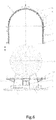
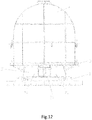
- the movable hot coil thermal insulation heat treatment device comprises a baseboard; a steel coil fixture provided at a central portion of an upper end surface of the baseboard; a tray which is an annular structure and horizontally arranged by nesting at a middle part of the steel coil fixture; a thermal insulation enclosure, which has an open lower end and an inner chamber having a volume larger than the steel coil, wherein the thermal insulation enclosure is arranged on the tray; an electric heating device provided on an inner side wall of the thermal insulation enclosure; a temperature sensor provided in the thermal insulation enclosure; and an information acquisition control module, wherein the electric heating device and the temperature sensor are electrically coupled to the information acquisition control module.
- the movable hot coil thermal insulation heat treatment device further comprises a gas protection device and a gas sensor which are electrically coupled to the information acquisition control module, respectively.
- a signal emitting module is provided in the information acquisition control module.
- the steel coil fixture comprises two juxtaposed support bodies, wherein upper end faces of the two support bodies are inclined surfaces and are arranged symmetrically; and a side sealing device is arranged at a gap between the two support bodies at each of two sides of the two support bodies.
- a bottom sealing device is arranged between bottoms of the two support bodies of the steel coil fixture to close the gap between the bottoms of the two support bodies.
- the bottom sealing device comprises a support plate provided between the two support bodies of the steel coil fixture, wherein the support plate is arranged vertically, and a plurality of rollers are provided on lower parts of two sides of the support plate at even spacings in a length direction to form a slidable mechanism; and a sealing plate provided horizontally on a top surface of the support plate, wherein the sealing plate has a size corresponding to the gap between the bottoms of the two support bodies.
- an electromagnetic block is provided on an end face of the support plate, and correspondingly, a metal stopper matching the electromagnetic block is provided between end portions of the two support bodies of the steel coil fixture at one side.
- the side sealing devices comprise:
- the bearing pedestal is provided on one side of the support body by using a fixing plate, wherein one side of the fixing plate is provided with a through hole for the rack to pass through, and a roller abutted against a top surface of the rack is provided at an outer side of the fixing plate above the through hole.
- the sealing plate and the sealing member have a composite layered structure, wherein an intermediate part of the structure is an insulating felt, and two sides of the intermediate part are cladded with a high temperature resistant steel plate.
- the sealing member is a right angle plate structure.
- a positioning sleeve is provided on a lower part of a side of the thermal insulation enclosure.
- a positioning pin matching the positioning sleeve is provided on the tray for the thermal insulation enclosure.
- the positioning pin is preferably a cone-shaped body.
- the thermal insulation enclosure is provided with a ventilation hole and a corresponding exhaust valve.
- the thermal insulation enclosure has a composite structure, comprising: an outer protection layer, which is a high-strength steel plate; an intermediate layer, which is a thermal insulation material; and an inner layer, which is a high temperature resistant stainless steel plate.
- the thermal insulation enclosure is a composite structure, comprising an inner radiation layer, an electric heating wire layer, an intermediate mesh cover, an intermediate thermal insulation layer, and an outer protection layer in order from inside to outside.
- the electric heating device is an electric heating wire
- the temperature sensor is a thermocouple sensor
- the steel coil transport cart transports the steel coil to the tray, and then the thermal insulation device is placed on the tray to insulate the steel coil at the earliest time.
- the thermal insulation enclosure and the steel coil move normally along the transport chain roller bed with no influence on the production operation of succeeding steel coils, while heat treatment is implemented during transportation.
- Transport cart lateral transmission roller bed device this device transfers an unloaded transport cart device bearing no thermal insulation enclosure from a back-haul transport chain roller bed to the heat treatment transport chain roller bed to realize transmission of the transport cart device to ensure that the transport cart can continue to receive another hot-rolled steel coil coming from the coiling station.
- the thermal insulation enclosure hoisting device lifts the thermal insulation enclosure from the transport cart device that carries the thermal insulation enclosure and moves on the back-haul transport chain roller bed, and then transfers the thermal insulation enclosure to the heat treatment transport chain roller bed to wait for next operation.
- a thermal insulation enclosure up-transfer hoisting device automatically places the thermal insulation enclosure on the transport cart device to achieve thermal insulation of the hot-rolled steel coil after the coiling of the steel.
- the transport cart device bearing a thermal insulation enclosure can satisfy the requirement of on-line heat treatment of a steel coil.
- the transport cart device can move on the transport chain roller bed and transport the steel coil that has been hot rolled and coiled to the thermal insulation zone of the transport chain to accomplish heat treatment.
- the thermal insulation enclosure and the transport cart device can be separated and combined by using a thermal insulation enclosure up-transfer hoisting device and a thermal insulation enclosure down-transfer hoisting device.
- Single thermal insulation enclosure zone a steel coil is subjected to thermal insulation heat treatment in a transport cart device bearing a thermal insulation enclosure.
- the purpose of heat treatment is achieved by controlling the running time of the transport cart device bearing a thermal insulation enclosure on the heat treatment transport chain roller bed.
- the layout of the single thermal insulation enclosure zone needs to be coordinated with the transport cart devices bearing thermal insulation enclosures, with the number of hot-rolled steel coils to be insulated and the time of insulation being taken into account. Assuming that the number of thermal insulation enclosures for hot steel coils is n, the number of steel coil transport carts on the production line should be > n + 1. After a thermal insulation enclosure is separated from a transport cart device at the thermal insulation enclosure down-transfer hoisting device, the thermal insulation enclosure, together with the transport cart, returns to the up-transfer hoisting device along the back-haul transport chain roller bed.
- special batches of hot-rolled strip steel can be subjected to special treatment such as in-depth processing when necessary, and heat treatment work stations can be added in the thermal insulation zone.
- the heat treatment work station is provided with a heating system for heating the interior of the thermal insulation enclosure and a protective cooling gas input system.
- a hot-rolled strip steel transport cart transports the hot-rolled steel coil to a work station where the heating system for heating the interior will heat the hot-rolled strip steel.
- Relevant heat treatment curves and process requirements may be utilized to perform the secondary heating of the steel coil to improve the overall performances of the hot-rolled strip steel.
- the transport cart device carrying a thermal insulation enclosure that has entered the processing work station is coupled to the protective cooling gas input system.
- the requirement for controlling the internal temperature of the thermal insulation enclosure device may be fulfilled by controlling the volume and proportion of the protective gas that is input. Relevant heat treatment curves and process requirements may be utilized to perform the secondary heating of the steel coil to improve the overall performances of the hot-rolled strip steel.
- the hot-rolled strip steel transport cart transports the hot-rolled strip steel to an information code printing station where the coil information will be printed on the steel coil. After it's confirmed that the steel coil separated from the thermal insulation enclosure carries the steel coil information, the steel coil is conveyed to the next production line for further processing.
- the heat-treated steel coil is transported along the transport chain roller bed to a steel coil warehouse, or transported via the transport chain system to the next working procedure of the production line to continue the production.
- the processing line is also provided with a heat treatment work station and an information code printing device.
- a special batch of hot-rolled strip steel may need to be subjected to special treatment such as in-depth processing in the heat treatment work station.
- a heat treatment work station may be added in the thermal insulation zone.
- the heat treatment work station is provided with a heating system for heating the interior of the thermal insulation enclosure and a protective cooling gas input system.
- Information code printing device a hot-rolled strip steel transport cart transports the hot-rolled strip steel to an information code printing station where the coil information will be printed on the steel coil.
- Heat-treated steel coils may be transported along the transport chain roller bed to a steel coil warehouse. If a steel coil needs cold rolling, flattening or trimming, a transport cart rotating roller bed device is used to transfer the steel coil to a transport chain roller bed in the next working procedure.
- thermal insulation enclosure exists individually and independently, and the temperature of each steel coil can be controlled during transportation on the transport chain. This saves time, and also improves production rhythm and efficiency.
- the hot-rolling on-line movable thermal insulation heat treatment process realizes on-line movable heat treatment of a hot coil by using a thermal insulation device directly after coiling of the hot coil.
- this process is used in place of the traditional off-line heat treatment, the purpose of improving product performances and plate shape quality, saving energy and reducing consumption can be achieved.
- Thermal insulation heat treatment of hot-rolled and cold-rolled high-strength steel hot coils in an "on-line mode" avoids the influence of air cooling after coiling on the performances of the steel coils, and improves the performances of the hot-rolled and cold-rolled high-strength steel.
- the present disclosure realizes on-line heat treatment during the transport chain transportation for a hot-rolled steel coil after coiling. After the steel coil leaves a coiler where the coiling is done, a movable hot coil thermal insulation heat treatment device is applied to the steel coil immediately. The heat of the steel coil itself is exploited to implement the heat treatment process including soaking and slow cooling of the steel coil to achieve the goals of high efficiency, energy saving and high yield rate.
- the strip steel coil is subjected to thermal insulation treatment at the earliest time.
- severe fluctuation of rolling force in cold rolling production, and failure to meet the tolerance standard for the thickness of final cold-rolled products are avoided.
- the rolling stability of cold-rolling - pickling - continuous rolling mills is improved, and the yield rate of cold-rolled ultra-high-strength steel is increased.
- a hot-rolling on-line movable thermal insulation heat treatment process is provided according to the present disclosure, wherein a slab is heated, rolled, laminar-flow cooled, and coiled to a hot coil state; after the hot coil is unloaded and bundled, a movable hot coil thermal insulation heat treatment device is applied to the hot coil within 30 minutes to start heat treatment on the hot coil while the hot coil is simultaneously transported on-line to a hot coil thermal insulation treatment zone; after heat treatment for a period of time of 1 to 48 hours, the steel coil is cooled in air and then sent to a warehouse, wherein a coiling temperature is controlled between 250 °C and 750 °C.
- the movable hot coil thermal insulation heat treatment device is applied to the hot coil within 10 minutes after the coiling is completed.
- the movable hot coil thermal insulation heat treatment device is a transport cart with a thermal insulation enclosure.
- a natural cooling rate in the movable hot coil thermal insulation heat treatment device is from 1 to 10 °C/h.
- a heating system and/or a vacuuming system and/or an inert gas filling system are provided in the movable hot coil thermal insulation heat treatment device.
- the thermal insulation heat treatment of hot-rolled and cold-rolled high-strength steel hot coils in an "on-line mode" avoids the influence of air cooling after coiling on the performances of the steel coils, and improves the performances of the hot-rolled and cold-rolled high-strength steel.
- a hot-rolled strip steel heat treatment line wherein a heat treatment transport chain roller bed 30 is provided between a bundling device 20 downstream of a hot-rolled steel coiler 10 and a cold rolling set; at least one movable hot coil thermal insulation heat treatment device 40 is provided on the heat treatment transport chain roller bed 30; correspondingly, hoisting devices 50, 50' capable of loading and unloading a steel coil to the movable hot coil thermal insulation heat treatment device are positioned respectively at two ends of the heat treatment transport chain roller bed 30; and a thermal insulation enclosure for closed on-line thermal insulation of the hot-rolled steel coil is provided on the movable hot coil thermal insulation heat treatment device 40.
- At least one heat treatment work station 80 is provided on the heat treatment transport chain roller bed 30 or the thermal insulation transport chain roller bed 70; a heating system for heating an interior of the thermal insulation enclosure in the movable hot coil thermal insulation heat treatment device and/or a protective cooling gas input system for gas cooling are provided in the heat treatment work station 80; 90 represents a rotating roller bed.
- a steel coil thermal insulation zone 60 is provided on one side of the heat treatment transport chain roller bed 10, wherein at least one thermal insulation transport chain roller bed 70 coupled to the heat treatment transport chain roller bed 70 and a hoisting device 50" are provided in the steel coil thermal insulation zone 60.
- an information code printing device 90 for printing steel coil information on the steel coil is provided at one end of the heat treatment transport chain roller bed 30 facing the cold rolling set.
- the movable hot coil thermal insulation heat treatment device 40 comprises:
- it further comprises a gas protection device and gas sensors 8, 8' which are electrically coupled to the information acquisition control module 7, respectively.
- a signal emitting module is provided in the information acquisition control module 7.
- the steel coil fixture 2 comprises two juxtaposed support bodies 21, 22, wherein upper end faces of the two support bodies 21, 22 are inclined surfaces and are arranged symmetrically; and side sealing devices 9, 9' are arranged at a gap between the two support bodies 21, 22 at two sides of the two support bodies 21, 22.
- a bottom sealing device 11 is arranged between bottoms of the two support bodies 21, 22 of the steel coil fixture 2 to close the gap between the bottoms of the two support bodies 21, 22.
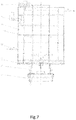
- the bottom sealing device 11 comprises:
- the sealing plate 113 has a composite layered structure, wherein an intermediate part of the structure is consisting of an insulating felt, and two side parts are high temperature resistant steel plates.
- an electromagnetic block 114 is provided on an end face of the support plate 111, and correspondingly, a metal stopper matching the electromagnetic block 114 is provided between end portions of the two support bodies 21, 22 of the steel coil fixture 2 at one side.
- the side sealing device 9 (which is taken as an example; the same below) comprises:
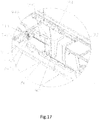
- the bearing pedestal 943 is provided on one side of the support body 221 by using a fixing plate 944, wherein one side of the fixing plate 945 is provided with a through hole 9451 for the rack 941 to pass through, and a roller 946 abutted against a top surface of the rack 941 is provided at an outer side of the fixing plate 945 above the through hole 945.
- the sealing member 93 has a composite layered structure, wherein an intermediate part of the structure is an insulating material, and two sides of the intermediate part are cladded with a high temperature resistant steel plate.
- the sealing member 93 is a right angle plate structure.
- a positioning sleeve 12 is provided on a lower part of a side of the thermal insulation enclosure 4.
- a positioning pin 13 matching the positioning sleeve 12 is provided on the tray 3 for the thermal insulation enclosure.
- the positioning pin 13 is preferably a cone-shaped body.
- the thermal insulation enclosure 4 is provided with a ventilation hole and a corresponding exhaust valve 41.
- the thermal insulation enclosure 4 has a composite structure, comprising: an outer protection layer, which is a high-strength steel plate; an intermediate layer, which is a thermal insulation material; and an inner layer, which is a high temperature resistant stainless steel plate.
- the thermal insulation enclosure 4 is a composite structure, comprising an inner radiation layer 42, an electric heating wire layer 43, an intermediate mesh cover 44, an intermediate thermal insulation layer 45, and an outer protection layer 46 in order from inside to outside.
- the composite structure of the thermal insulation enclosure is fixed with an anchor nail 47.
- the thermal insulation enclosure 4 is a square thermal insulation enclosure or a circular thermal insulation enclosure.
- the electric heating device 5 is an electric heating wire
- the temperature sensor 6 is a thermocouple sensor
- the thermal insulation treatment of a strip steel coil after coiling also fulfils the purpose of annealing treatment by making use of the residual heat in the steel coil that has just been coiled, which greatly addresses the challenges of insufficient performance improvement caused by the excessively long time from coiling to entry of the steel coil to the slow cooling device, and large performance fluctuation of the strip steel in the length and width directions.
- a special batch of hot-rolled strip steel may need to be subjected to special treatment such as in-depth processing.
- the heating device and protective cooling gas input system provided in the thermal insulation enclosure can cooperate to achieve temperature control under necessary conditions.
Landscapes
- Chemical & Material Sciences (AREA)
- Engineering & Computer Science (AREA)
- Mechanical Engineering (AREA)
- Materials Engineering (AREA)
- Crystallography & Structural Chemistry (AREA)
- Thermal Sciences (AREA)
- Physics & Mathematics (AREA)
- Metallurgy (AREA)
- Organic Chemistry (AREA)
- General Engineering & Computer Science (AREA)
- Heat Treatments In General, Especially Conveying And Cooling (AREA)
- Heat Treatment Of Strip Materials And Filament Materials (AREA)
- Winding, Rewinding, Material Storage Devices (AREA)
Applications Claiming Priority (4)
| Application Number | Priority Date | Filing Date | Title |
|---|---|---|---|
| CN201710853613.3A CN107470377A (zh) | 2017-09-20 | 2017-09-20 | 钢带制造流水线在线保温缓冷装置 |
| CN201810632238.4A CN110616307A (zh) | 2018-06-19 | 2018-06-19 | 一种热轧带钢热处理线 |
| CN201810632237.XA CN110616306A (zh) | 2018-06-19 | 2018-06-19 | 一种热轧在线移动保温热处理工艺 |
| PCT/CN2018/106709 WO2019057116A1 (zh) | 2017-09-20 | 2018-09-20 | 一种热轧在线移动保温热处理工艺及热处理线 |
Publications (3)
| Publication Number | Publication Date |
|---|---|
| EP3685931A1 true EP3685931A1 (de) | 2020-07-29 |
| EP3685931A4 EP3685931A4 (de) | 2021-08-11 |
| EP3685931B1 EP3685931B1 (de) | 2023-08-23 |
Family
ID=65810629
Family Applications (1)
| Application Number | Title | Priority Date | Filing Date |
|---|---|---|---|
| EP18859703.3A Active EP3685931B1 (de) | 2017-09-20 | 2018-09-20 | Inline-verfahren zur wärmebehandlung mit mobiler wärmedämmung durch heisswalzen und wärmebehandlungslinie |
Country Status (4)
| Country | Link |
|---|---|
| EP (1) | EP3685931B1 (de) |
| JP (1) | JP7253558B2 (de) |
| KR (1) | KR20200066630A (de) |
| WO (1) | WO2019057116A1 (de) |
Families Citing this family (3)
| Publication number | Priority date | Publication date | Assignee | Title |
|---|---|---|---|---|
| CN113355496B (zh) * | 2021-06-04 | 2022-09-13 | 东北大学 | 一种不锈钢热轧卷轧制余热在线固溶退火工艺 |
| JP7687195B2 (ja) * | 2021-11-17 | 2025-06-03 | 大同特殊鋼株式会社 | 鋼材の製造方法および製造装置 |
| CN116692296A (zh) * | 2023-06-25 | 2023-09-05 | 中冶华天工程技术有限公司 | 一种模块式保温设备 |
Family Cites Families (20)
| Publication number | Priority date | Publication date | Assignee | Title |
|---|---|---|---|---|
| RO75367A (ro) * | 1977-11-25 | 1980-11-30 | Alleghany Ludlum Industries,Inc.,Us | Cuptor pentru recoacerea benzilor metalice sub forma de colaci |
| JPS5837128A (ja) * | 1981-08-26 | 1983-03-04 | Nippon Kokan Kk <Nkk> | 連続焼鈍用Alキルド鋼板の製造方法 |
| JPS60110816A (ja) * | 1983-11-17 | 1985-06-17 | Nippon Steel Corp | 熱延鋼帯の軟化方法 |
| JPS60125329A (ja) * | 1983-12-07 | 1985-07-04 | Kawasaki Steel Corp | 熱間圧延鋼帯の製造方法 |
| JPS60218431A (ja) * | 1984-04-12 | 1985-11-01 | Sumitomo Metal Ind Ltd | 熱間鋼帯コイルの冷却方法 |
| JPS61159534A (ja) * | 1985-01-05 | 1986-07-19 | Nippon Steel Corp | 電縫鋼管用熱延鋼帯の製造方法 |
| JP3449310B2 (ja) | 1999-09-02 | 2003-09-22 | Jfeスチール株式会社 | 酸洗性とコイル内材質均一性に優れた熱延鋼板の製造方法 |
| JP3744279B2 (ja) * | 1999-09-09 | 2006-02-08 | Jfeスチール株式会社 | スケール密着性に優れた高炭素熱延鋼板の製造方法 |
| US20020076289A1 (en) * | 2000-12-15 | 2002-06-20 | National Steel Car Limited | Insulated triple trough coil car |
| CN101413051B (zh) | 2008-06-20 | 2010-11-17 | 北京首钢国际工程技术有限公司 | 在线热处理线材收集运输系统 |
| JP5546118B2 (ja) | 2008-10-16 | 2014-07-09 | 株式会社神戸製鋼所 | コイル徐冷装置 |
| CN202316643U (zh) * | 2011-11-14 | 2012-07-11 | 天津市中重科技工程有限公司 | 双工位无芯移送式热卷箱 |
| CN103057842A (zh) * | 2013-01-15 | 2013-04-24 | 无锡亚中智能装备有限公司 | 车载式硅钢卷恒温装置 |
| CN203064459U (zh) * | 2013-01-15 | 2013-07-17 | 无锡亚中智能装备有限公司 | 车载式硅钢卷恒温装置 |
| CN203497055U (zh) * | 2013-09-23 | 2014-03-26 | 上海宝冶集团有限公司 | 双向保温挂车 |
| CN104087839B (zh) * | 2014-07-18 | 2016-05-25 | 武汉钢铁(集团)公司 | 热轧超薄激光焊接锯片基体用钢及生产方法 |
| KR101589913B1 (ko) | 2014-12-10 | 2016-02-01 | 주식회사 포스코 | Ahss 열연코일의 열처리 방법 및 이를 이용한 냉간 압연방법 |
| CN206447906U (zh) * | 2017-01-05 | 2017-08-29 | 鞍钢集团工程技术有限公司 | 一种移动式缓冷间 |
| CN107470377A (zh) * | 2017-09-20 | 2017-12-15 | 上海贺力液压机电有限公司 | 钢带制造流水线在线保温缓冷装置 |
| CN207170521U (zh) * | 2017-09-20 | 2018-04-03 | 上海贺力液压机电有限公司 | 钢带制造流水线在线保温缓冷装置 |
-
2018
- 2018-09-20 WO PCT/CN2018/106709 patent/WO2019057116A1/zh not_active Ceased
- 2018-09-20 EP EP18859703.3A patent/EP3685931B1/de active Active
- 2018-09-20 KR KR1020207010727A patent/KR20200066630A/ko not_active Ceased
- 2018-09-20 JP JP2020537826A patent/JP7253558B2/ja active Active
Also Published As
| Publication number | Publication date |
|---|---|
| KR20200066630A (ko) | 2020-06-10 |
| EP3685931A4 (de) | 2021-08-11 |
| WO2019057116A1 (zh) | 2019-03-28 |
| JP7253558B2 (ja) | 2023-04-06 |
| EP3685931B1 (de) | 2023-08-23 |
| JP2020534440A (ja) | 2020-11-26 |
Similar Documents
| Publication | Publication Date | Title |
|---|---|---|
| WO2017167147A1 (zh) | 热冲压成形加热装置及热冲压生产线 | |
| CN112872064B (zh) | 一种酸洗用低碳热轧窄带钢氧化铁皮控制工艺 | |
| EP3685931B1 (de) | Inline-verfahren zur wärmebehandlung mit mobiler wärmedämmung durch heisswalzen und wärmebehandlungslinie | |
| CN111346914A (zh) | 一种改善汽车外板表面质量的热轧工艺方法 | |
| KR102397795B1 (ko) | 이동식 열간 압연 열절연 열처리 장치 | |
| CN212444119U (zh) | 一种铝合金卷材/板材的生产系统 | |
| CN108441621A (zh) | 一种移动式热卷保温热处理装置 | |
| CN102658301A (zh) | 热轧带钢氧化铁皮控制及改性机组 | |
| CN201744485U (zh) | 一种生产宽厚板产品的系统 | |
| JP6583638B2 (ja) | アルミニウムシリコンを鋼板表面内に拡散する技術 | |
| JP6260448B2 (ja) | 熱延鋼帯の熱処理設備 | |
| CN108559834A (zh) | 一种固定式热卷保温热处理装置 | |
| CN105414177B (zh) | 一种冷轧超高强钢短流程生产加工工艺及设备 | |
| CN110614281A (zh) | 一种热轧黑皮钢产品改善氧化铁皮附着力的方法 | |
| CN208616737U (zh) | 一种带保温罩的运输小车 | |
| JP6952197B2 (ja) | 固定式熱間コイル保温熱処理装置 | |
| CN208617953U (zh) | 一种固定式热卷保温热处理装置 | |
| CN214142444U (zh) | 一种移动式热卷退火装置 | |
| CN114214485B (zh) | 一种铁素体不锈钢热轧热卷板的一火热装热处理工艺 | |
| CN101509726B (zh) | 板坯加热设备和板坯加热生产线 | |
| JP2016148063A (ja) | 高強度鋼板の製造方法および処理施設 | |
| CN112899457B (zh) | 可替代高磁感取向硅钢常化退火的热处理方法 | |
| CN110616299A (zh) | 一种高强钢的生产方法 | |
| CN110616307A (zh) | 一种热轧带钢热处理线 | |
| CN110616306A (zh) | 一种热轧在线移动保温热处理工艺 |
Legal Events
| Date | Code | Title | Description |
|---|---|---|---|
| STAA | Information on the status of an ep patent application or granted ep patent |
Free format text: STATUS: THE INTERNATIONAL PUBLICATION HAS BEEN MADE |
|
| PUAI | Public reference made under article 153(3) epc to a published international application that has entered the european phase |
Free format text: ORIGINAL CODE: 0009012 |
|
| STAA | Information on the status of an ep patent application or granted ep patent |
Free format text: STATUS: REQUEST FOR EXAMINATION WAS MADE |
|
| 17P | Request for examination filed |
Effective date: 20200324 |
|
| AK | Designated contracting states |
Kind code of ref document: A1 Designated state(s): AL AT BE BG CH CY CZ DE DK EE ES FI FR GB GR HR HU IE IS IT LI LT LU LV MC MK MT NL NO PL PT RO RS SE SI SK SM TR |
|
| AX | Request for extension of the european patent |
Extension state: BA ME |
|
| DAV | Request for validation of the european patent (deleted) | ||
| DAX | Request for extension of the european patent (deleted) | ||
| REG | Reference to a national code |
Ref country code: DE Ipc: C21D0009520000 Ref country code: DE Ref legal event code: R079 Ref document number: 602018056129 Country of ref document: DE Free format text: PREVIOUS MAIN CLASS: B21B0045000000 Ipc: C21D0009520000 |
|
| A4 | Supplementary search report drawn up and despatched |
Effective date: 20210712 |
|
| RIC1 | Information provided on ipc code assigned before grant |
Ipc: C21D 9/52 20060101AFI20210706BHEP Ipc: B21B 1/26 20060101ALI20210706BHEP Ipc: C21D 1/22 20060101ALI20210706BHEP Ipc: C21D 1/84 20060101ALI20210706BHEP Ipc: C21D 8/02 20060101ALI20210706BHEP Ipc: F27B 11/00 20060101ALI20210706BHEP Ipc: C21D 9/00 20060101ALI20210706BHEP Ipc: C21D 9/673 20060101ALI20210706BHEP Ipc: C21D 9/675 20060101ALI20210706BHEP Ipc: C21D 9/677 20060101ALI20210706BHEP Ipc: B21B 45/00 20060101ALI20210706BHEP |
|
| GRAP | Despatch of communication of intention to grant a patent |
Free format text: ORIGINAL CODE: EPIDOSNIGR1 |
|
| STAA | Information on the status of an ep patent application or granted ep patent |
Free format text: STATUS: GRANT OF PATENT IS INTENDED |
|
| INTG | Intention to grant announced |
Effective date: 20230303 |
|
| GRAS | Grant fee paid |
Free format text: ORIGINAL CODE: EPIDOSNIGR3 |
|
| GRAA | (expected) grant |
Free format text: ORIGINAL CODE: 0009210 |
|
| STAA | Information on the status of an ep patent application or granted ep patent |
Free format text: STATUS: THE PATENT HAS BEEN GRANTED |
|
| AK | Designated contracting states |
Kind code of ref document: B1 Designated state(s): AL AT BE BG CH CY CZ DE DK EE ES FI FR GB GR HR HU IE IS IT LI LT LU LV MC MK MT NL NO PL PT RO RS SE SI SK SM TR |
|
| REG | Reference to a national code |
Ref country code: GB Ref legal event code: FG4D |
|
| REG | Reference to a national code |
Ref country code: CH Ref legal event code: EP |
|
| REG | Reference to a national code |
Ref country code: IE Ref legal event code: FG4D |
|
| REG | Reference to a national code |
Ref country code: DE Ref legal event code: R096 Ref document number: 602018056129 Country of ref document: DE |
|
| REG | Reference to a national code |
Ref country code: LT Ref legal event code: MG9D |
|
| REG | Reference to a national code |
Ref country code: NL Ref legal event code: MP Effective date: 20230823 |
|
| REG | Reference to a national code |
Ref country code: AT Ref legal event code: MK05 Ref document number: 1602666 Country of ref document: AT Kind code of ref document: T Effective date: 20230823 |
|
| PG25 | Lapsed in a contracting state [announced via postgrant information from national office to epo] |
Ref country code: GR Free format text: LAPSE BECAUSE OF FAILURE TO SUBMIT A TRANSLATION OF THE DESCRIPTION OR TO PAY THE FEE WITHIN THE PRESCRIBED TIME-LIMIT Effective date: 20231124 |
|
| PG25 | Lapsed in a contracting state [announced via postgrant information from national office to epo] |
Ref country code: IS Free format text: LAPSE BECAUSE OF FAILURE TO SUBMIT A TRANSLATION OF THE DESCRIPTION OR TO PAY THE FEE WITHIN THE PRESCRIBED TIME-LIMIT Effective date: 20231223 |
|
| PG25 | Lapsed in a contracting state [announced via postgrant information from national office to epo] |
Ref country code: SE Free format text: LAPSE BECAUSE OF FAILURE TO SUBMIT A TRANSLATION OF THE DESCRIPTION OR TO PAY THE FEE WITHIN THE PRESCRIBED TIME-LIMIT Effective date: 20230823 Ref country code: RS Free format text: LAPSE BECAUSE OF FAILURE TO SUBMIT A TRANSLATION OF THE DESCRIPTION OR TO PAY THE FEE WITHIN THE PRESCRIBED TIME-LIMIT Effective date: 20230823 Ref country code: PT Free format text: LAPSE BECAUSE OF FAILURE TO SUBMIT A TRANSLATION OF THE DESCRIPTION OR TO PAY THE FEE WITHIN THE PRESCRIBED TIME-LIMIT Effective date: 20231226 Ref country code: NO Free format text: LAPSE BECAUSE OF FAILURE TO SUBMIT A TRANSLATION OF THE DESCRIPTION OR TO PAY THE FEE WITHIN THE PRESCRIBED TIME-LIMIT Effective date: 20231123 Ref country code: NL Free format text: LAPSE BECAUSE OF FAILURE TO SUBMIT A TRANSLATION OF THE DESCRIPTION OR TO PAY THE FEE WITHIN THE PRESCRIBED TIME-LIMIT Effective date: 20230823 Ref country code: LV Free format text: LAPSE BECAUSE OF FAILURE TO SUBMIT A TRANSLATION OF THE DESCRIPTION OR TO PAY THE FEE WITHIN THE PRESCRIBED TIME-LIMIT Effective date: 20230823 Ref country code: LT Free format text: LAPSE BECAUSE OF FAILURE TO SUBMIT A TRANSLATION OF THE DESCRIPTION OR TO PAY THE FEE WITHIN THE PRESCRIBED TIME-LIMIT Effective date: 20230823 Ref country code: IS Free format text: LAPSE BECAUSE OF FAILURE TO SUBMIT A TRANSLATION OF THE DESCRIPTION OR TO PAY THE FEE WITHIN THE PRESCRIBED TIME-LIMIT Effective date: 20231223 Ref country code: HR Free format text: LAPSE BECAUSE OF FAILURE TO SUBMIT A TRANSLATION OF THE DESCRIPTION OR TO PAY THE FEE WITHIN THE PRESCRIBED TIME-LIMIT Effective date: 20230823 Ref country code: GR Free format text: LAPSE BECAUSE OF FAILURE TO SUBMIT A TRANSLATION OF THE DESCRIPTION OR TO PAY THE FEE WITHIN THE PRESCRIBED TIME-LIMIT Effective date: 20231124 Ref country code: FI Free format text: LAPSE BECAUSE OF FAILURE TO SUBMIT A TRANSLATION OF THE DESCRIPTION OR TO PAY THE FEE WITHIN THE PRESCRIBED TIME-LIMIT Effective date: 20230823 Ref country code: AT Free format text: LAPSE BECAUSE OF FAILURE TO SUBMIT A TRANSLATION OF THE DESCRIPTION OR TO PAY THE FEE WITHIN THE PRESCRIBED TIME-LIMIT Effective date: 20230823 |
|
| PG25 | Lapsed in a contracting state [announced via postgrant information from national office to epo] |
Ref country code: PL Free format text: LAPSE BECAUSE OF FAILURE TO SUBMIT A TRANSLATION OF THE DESCRIPTION OR TO PAY THE FEE WITHIN THE PRESCRIBED TIME-LIMIT Effective date: 20230823 |
|
| PG25 | Lapsed in a contracting state [announced via postgrant information from national office to epo] |
Ref country code: ES Free format text: LAPSE BECAUSE OF FAILURE TO SUBMIT A TRANSLATION OF THE DESCRIPTION OR TO PAY THE FEE WITHIN THE PRESCRIBED TIME-LIMIT Effective date: 20230823 |
|
| PG25 | Lapsed in a contracting state [announced via postgrant information from national office to epo] |
Ref country code: SM Free format text: LAPSE BECAUSE OF FAILURE TO SUBMIT A TRANSLATION OF THE DESCRIPTION OR TO PAY THE FEE WITHIN THE PRESCRIBED TIME-LIMIT Effective date: 20230823 Ref country code: RO Free format text: LAPSE BECAUSE OF FAILURE TO SUBMIT A TRANSLATION OF THE DESCRIPTION OR TO PAY THE FEE WITHIN THE PRESCRIBED TIME-LIMIT Effective date: 20230823 Ref country code: ES Free format text: LAPSE BECAUSE OF FAILURE TO SUBMIT A TRANSLATION OF THE DESCRIPTION OR TO PAY THE FEE WITHIN THE PRESCRIBED TIME-LIMIT Effective date: 20230823 Ref country code: EE Free format text: LAPSE BECAUSE OF FAILURE TO SUBMIT A TRANSLATION OF THE DESCRIPTION OR TO PAY THE FEE WITHIN THE PRESCRIBED TIME-LIMIT Effective date: 20230823 Ref country code: DK Free format text: LAPSE BECAUSE OF FAILURE TO SUBMIT A TRANSLATION OF THE DESCRIPTION OR TO PAY THE FEE WITHIN THE PRESCRIBED TIME-LIMIT Effective date: 20230823 Ref country code: CZ Free format text: LAPSE BECAUSE OF FAILURE TO SUBMIT A TRANSLATION OF THE DESCRIPTION OR TO PAY THE FEE WITHIN THE PRESCRIBED TIME-LIMIT Effective date: 20230823 Ref country code: SK Free format text: LAPSE BECAUSE OF FAILURE TO SUBMIT A TRANSLATION OF THE DESCRIPTION OR TO PAY THE FEE WITHIN THE PRESCRIBED TIME-LIMIT Effective date: 20230823 |
|
| REG | Reference to a national code |
Ref country code: CH Ref legal event code: PL |
|
| PG25 | Lapsed in a contracting state [announced via postgrant information from national office to epo] |
Ref country code: LU Free format text: LAPSE BECAUSE OF NON-PAYMENT OF DUE FEES Effective date: 20230920 |
|
| REG | Reference to a national code |
Ref country code: DE Ref legal event code: R097 Ref document number: 602018056129 Country of ref document: DE |
|
| REG | Reference to a national code |
Ref country code: BE Ref legal event code: MM Effective date: 20230930 |
|
| PG25 | Lapsed in a contracting state [announced via postgrant information from national office to epo] |
Ref country code: MC Free format text: LAPSE BECAUSE OF FAILURE TO SUBMIT A TRANSLATION OF THE DESCRIPTION OR TO PAY THE FEE WITHIN THE PRESCRIBED TIME-LIMIT Effective date: 20230823 Ref country code: LU Free format text: LAPSE BECAUSE OF NON-PAYMENT OF DUE FEES Effective date: 20230920 |
|
| PLBE | No opposition filed within time limit |
Free format text: ORIGINAL CODE: 0009261 |
|
| STAA | Information on the status of an ep patent application or granted ep patent |
Free format text: STATUS: NO OPPOSITION FILED WITHIN TIME LIMIT |
|
| REG | Reference to a national code |
Ref country code: IE Ref legal event code: MM4A |
|
| PG25 | Lapsed in a contracting state [announced via postgrant information from national office to epo] |
Ref country code: IE Free format text: LAPSE BECAUSE OF NON-PAYMENT OF DUE FEES Effective date: 20230920 |
|
| PG25 | Lapsed in a contracting state [announced via postgrant information from national office to epo] |
Ref country code: CH Free format text: LAPSE BECAUSE OF NON-PAYMENT OF DUE FEES Effective date: 20230930 |
|
| GBPC | Gb: european patent ceased through non-payment of renewal fee |
Effective date: 20231123 |
|
| 26N | No opposition filed |
Effective date: 20240524 |
|
| PG25 | Lapsed in a contracting state [announced via postgrant information from national office to epo] |
Ref country code: IE Free format text: LAPSE BECAUSE OF NON-PAYMENT OF DUE FEES Effective date: 20230920 Ref country code: CH Free format text: LAPSE BECAUSE OF NON-PAYMENT OF DUE FEES Effective date: 20230930 Ref country code: SI Free format text: LAPSE BECAUSE OF FAILURE TO SUBMIT A TRANSLATION OF THE DESCRIPTION OR TO PAY THE FEE WITHIN THE PRESCRIBED TIME-LIMIT Effective date: 20230823 |
|
| PG25 | Lapsed in a contracting state [announced via postgrant information from national office to epo] |
Ref country code: BE Free format text: LAPSE BECAUSE OF NON-PAYMENT OF DUE FEES Effective date: 20230930 |
|
| PG25 | Lapsed in a contracting state [announced via postgrant information from national office to epo] |
Ref country code: GB Free format text: LAPSE BECAUSE OF NON-PAYMENT OF DUE FEES Effective date: 20231123 |
|
| PG25 | Lapsed in a contracting state [announced via postgrant information from national office to epo] |
Ref country code: GB Free format text: LAPSE BECAUSE OF NON-PAYMENT OF DUE FEES Effective date: 20231123 |
|
| PG25 | Lapsed in a contracting state [announced via postgrant information from national office to epo] |
Ref country code: BG Free format text: LAPSE BECAUSE OF FAILURE TO SUBMIT A TRANSLATION OF THE DESCRIPTION OR TO PAY THE FEE WITHIN THE PRESCRIBED TIME-LIMIT Effective date: 20230823 |
|
| PG25 | Lapsed in a contracting state [announced via postgrant information from national office to epo] |
Ref country code: BG Free format text: LAPSE BECAUSE OF FAILURE TO SUBMIT A TRANSLATION OF THE DESCRIPTION OR TO PAY THE FEE WITHIN THE PRESCRIBED TIME-LIMIT Effective date: 20230823 |
|
| PG25 | Lapsed in a contracting state [announced via postgrant information from national office to epo] |
Ref country code: CY Free format text: LAPSE BECAUSE OF FAILURE TO SUBMIT A TRANSLATION OF THE DESCRIPTION OR TO PAY THE FEE WITHIN THE PRESCRIBED TIME-LIMIT; INVALID AB INITIO Effective date: 20180920 |
|
| PG25 | Lapsed in a contracting state [announced via postgrant information from national office to epo] |
Ref country code: HU Free format text: LAPSE BECAUSE OF FAILURE TO SUBMIT A TRANSLATION OF THE DESCRIPTION OR TO PAY THE FEE WITHIN THE PRESCRIBED TIME-LIMIT; INVALID AB INITIO Effective date: 20180920 |
|
| PGFP | Annual fee paid to national office [announced via postgrant information from national office to epo] |
Ref country code: DE Payment date: 20250730 Year of fee payment: 8 |
|
| PGFP | Annual fee paid to national office [announced via postgrant information from national office to epo] |
Ref country code: IT Payment date: 20250825 Year of fee payment: 8 |
|
| PGFP | Annual fee paid to national office [announced via postgrant information from national office to epo] |
Ref country code: FR Payment date: 20250721 Year of fee payment: 8 |
|
| PG25 | Lapsed in a contracting state [announced via postgrant information from national office to epo] |
Ref country code: TR Free format text: LAPSE BECAUSE OF FAILURE TO SUBMIT A TRANSLATION OF THE DESCRIPTION OR TO PAY THE FEE WITHIN THE PRESCRIBED TIME-LIMIT Effective date: 20230823 |