EP3686061A1 - Adaptateur pour un véhicule automobile - Google Patents
Adaptateur pour un véhicule automobile Download PDFInfo
- Publication number
- EP3686061A1 EP3686061A1 EP20153323.9A EP20153323A EP3686061A1 EP 3686061 A1 EP3686061 A1 EP 3686061A1 EP 20153323 A EP20153323 A EP 20153323A EP 3686061 A1 EP3686061 A1 EP 3686061A1
- Authority
- EP
- European Patent Office
- Prior art keywords
- adapter
- holding plate
- locking
- vehicle
- holder
- Prior art date
- Legal status (The legal status is an assumption and is not a legal conclusion. Google has not performed a legal analysis and makes no representation as to the accuracy of the status listed.)
- Granted
Links
Images






Classifications
-
- B—PERFORMING OPERATIONS; TRANSPORTING
- B60—VEHICLES IN GENERAL
- B60R—VEHICLES, VEHICLE FITTINGS, OR VEHICLE PARTS, NOT OTHERWISE PROVIDED FOR
- B60R7/00—Stowing or holding appliances inside vehicle primarily intended for personal property smaller than suit-cases, e.g. travelling articles, or maps
- B60R7/04—Stowing or holding appliances inside vehicle primarily intended for personal property smaller than suit-cases, e.g. travelling articles, or maps in driver or passenger space, e.g. using racks
- B60R7/043—Stowing or holding appliances inside vehicle primarily intended for personal property smaller than suit-cases, e.g. travelling articles, or maps in driver or passenger space, e.g. using racks mounted on or under a seat
Definitions
- the invention relates to an adapter for a motor vehicle.
- test equipment When developing motor vehicles, test equipment usually has to be transported on board the vehicle during test drives.
- the measurement technology is very often located in the interior of the motor vehicle, for example in order to have access to the measurement technology during the test drive.
- the measuring technology is lashed down so that the measuring technology does not slip while driving.
- Lashing is a comparatively long process and lashing must be carried out with the greatest care so that the measurement technology is securely connected to the vehicle while driving.
- the problem is that lashing eyes are not attached everywhere on the vehicle, so that lashing can only be possible under difficult conditions.
- an object of the invention to provide an adapter for a motor vehicle, which quickly and easily connects objects connected to the adapter, such as measurement technology, to the motor vehicle.
- the solution according to the invention consists of an adapter with the features of claim 1.
- the adapter By locking the adapter, a very secure and quick connection of the adapter to the motor vehicle and thus also to the object attached to the adapter is possible.
- object is to be understood very generally, for example the term measurement technology includes a holder for a briefcase, a shopping basket, a drinks crate, a box or boxes, for example for the transport of animals, a laptop holder, for example for field workers or To understand measurement technicians or the like.
- the bracket attached to the motor vehicle is an Isofix bracket.
- the latching device advantageously comprises a lower and an upper latching finger.
- the locking fingers expediently latch with the holder.
- the locking fingers are expediently locked in the first position.
- the locking fingers expediently release the holder.
- the holder is expediently an eyelet, in particular a metallic eyelet.
- the holder is particularly useful a metal bracket that is firmly connected to the vehicle. It may be expedient for the metal bracket to be designed as a glasses bracket.
- the locking fingers are advantageously designed as claws, which can be pivoted towards and away from one another in particular. It can also be advantageous for the latching fingers to be designed as pliers that can be rotated, in particular, and that at least partially, in particular completely, grip the holder in the first position. It may be expedient that only one of the two locking fingers is pivotable and / or rotatable, whereas in particular the other of the two locking fingers is fixed.
- the latching device is preferably displaceable relative to the holding plate.
- the latching device is particularly advantageously displaceable parallel to the holding plate.
- the holding plate expediently comprises a locking device with which the latching device can be locked on the holding plate.
- the holding plate on which the object is arranged can in particular be displaced approximately parallel to the direction of travel, in particular to the backrest.
- the position of the object, in particular the measuring device can thus be set.
- the measuring devices and / or the holding plate or an auxiliary support connected to the holding plate in the ready-to-drive state are particularly advantageously attached as close as possible to the backrest, possibly even against their upholstery or even day frame structure tense. In this way, a particularly good fixation is achieved, for. B.
- the adapter carries one or more measuring devices which are supposed to record body movements and / or accelerations as unadulterated as possible.
- a spacer for holding a distance between the vehicle seat and the holding plate is advantageously provided on the underside of the holding plate, and the object can be fastened on the upper side opposite the underside.
- This enables the object to be fastened to the holding plate, for example as a screw connection, the fastening, for example the screw or the nut, not lying directly on the seat. The distance therefore reduces or prevents damage to the seat.
- the spacer preferably comprises two, in particular parallel, locking arms.
- one of the locking devices is arranged at each end of the locking arms. This enables a very stable basic structure of the adapter, but the adapter is nevertheless light.
- the locking arms are guided in such a way on the spacer or on the holding plate and cooperate with a locking device in such a way that the locking arms can be displaced relative to the spacers or relative to the holding plate in and against a displacement direction P as long as the locking device is not activated. Then they are fixed on the spacers or on the holding plate when the locking device is activated.
- the locking device is a ratchet mechanism.
- this allows the latching arms in this way, preferably in the manner of a telescope, can be shifted relative to the spacer assigned to them or relative to the holding plate in such a way that the end face of the holding plate directly opposite a rear seat backrest of the vehicle comes closer to the rear seat backrest or even compresses its upholstery locally, whereupon the locking arm concerned preferably preferably automatically in this position the spacer assigned to it is determined.
- the locking device is a ratchet mechanism, a ratchet mechanism or another self-locking mechanism which allows the holding plate to be pushed ever closer to the rear seat backrest or to compress it more and more, but prevents the holding plate from moving from a locked position once again in the opposite direction, away from the Rear seat back moves.
- the locking device is designed in such a way that it allows the following energy-saving alternating movement or the following method:
- the locking fingers of the locking device are positively connected to their holding partner on the vehicle.
- the locking arms are displaced together relative to the holding plate and / or the spacers in such a way that the holding plate, or its auxiliary support, or the measuring devices or the other payload rest on the holding plate against the rear seat back or its upholstery.
- step 1 one of the locking arms is shifted at least by one locking position, where it then snaps into place, so that the holding plate, or its auxiliary support, or the measuring devices on its side lie even more closely against the rear seat back or compress their padding (compress even more if necessary).
- step 2 the locking arm on the other side. If necessary, steps 1 and 2 will then be repeated or even repeated repeated. This means that with much less force or maximum force per step, a very intimate concern against the back seat backrest or a very strong tension against its upholstery can be achieved - which would often not be possible if you squeeze the padding of the back seat backrest over its entire width in a single step should.
- At least one handle preferably in the form of at least one handle bar, is attached to the front side of the holding plate opposite to the rear seat back, which facilitates the practice of the "interchangeable feed method".
- the adapter expediently comprises a support bracket to prevent rotation around the holder.
- the support bracket comprises a handle for holding the adapter.
- the support bracket provides a second fixation, which prevents the adapter from rotating around the fixation.
- the handle also makes it easier to install and remove the adapter in the vehicle.
- the adapter advantageously comprises a seat plate which is fixedly connected to the holding plate at a distance from the holding plate, the seat plate being provided for placing the adapter on the vehicle seat.
- This provides a flat contact surface for the adapter, so that the adapter distributes the weight evenly and the seat is not damaged even when the object attached to the adapter is heavy.
- the adapter preferably comprises a retaining bracket, the retaining bracket being arranged in particular on the end face, in particular on the end face of the adapter which faces away from the latching device. This allows the adapter to be easily installed and removed.
- the bracket can also be used in particular to lash the adapter additionally.
- the adapter particularly advantageously comprises a floor support.
- the Floor support is arranged in particular on the holding plate, on the seat plate, on the holding bracket, or on one or on both latching arms, in particular firmly and particularly advantageously non-rotatably connected.
- the floor support is arranged in particular on the end face, in particular on the end face of the adapter facing away from the latching device.
- the floor support extends to the vehicle floor in the interior of the vehicle. In the event of sudden sudden deceleration of the vehicle and / or in the case of heavy measuring devices, the floor support prevents the measuring device carrier from immersing into the vehicle seat together with the measuring devices and thus the measuring devices moving translationally and / or rotationally in the direction of the vehicle floor.
- the fastening device is expediently releasable and in particular a screw connection, a clamping device or a bayonet connection. This allows the adapter to be equipped with various objects.
- the fastening device expediently comprises a ball joint.
- the ball joint expediently comprises a quick release, which fixes the ball joint, so that the joint is fixed.
- a holder for an object, in particular a laptop, measuring device or the like, is expediently attached to the ball joint.
- the bracket can be aligned horizontally due to the ball joint.
- the holder can also be expediently aligned in a plane outside the horizontal, which, for example, enables the object, in particular the laptop, to be operated comfortably.
- the fact that seats are usually slightly inclined in the vehicle means that the ball joint can be used to compensate for the inclination on the object.
- the object can be aligned almost arbitrarily, so that the object can be operated or used.
- the invention advantageously comprises a laptop holder for a motor vehicle, the laptop holder comprising an adapter according to one of claims 1 to 7, and the laptop holder being fastened to the fastening device of the laptop holder.
- the invention expediently comprises a measuring device fastening device for a motor vehicle, the measuring device fastening device comprising an adapter according to one of claims 1 to 7, the measuring device fastening device being fastened to the fastening device of the holding plate of the adapter, and the measuring device fastening device being provided for fastening measurement technology in the vehicle.
- the adapter according to the invention should not be limited to the application and embodiment described above.
- the adapter according to the invention can have a number that differs from a number of individual elements, components and units specified here in order to fulfill a function described here.
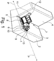
- a first embodiment of an adapter 1 is shown.
- the adapter 1 rests on a seat 3 of a vehicle seat 2, also called a seat, of a vehicle, not shown.
- the adapter 1 is based on a backrest 4 of the seat 2.
- the vehicle seat 2 comprises a holder, not shown.
- the adapter 1 comprises a latching device 5, which is provided for latching the adapter 1 with the holder attached to the vehicle seat 2.
- Fig. 1 shows the adapter 1 in the locked state with the holder on the vehicle seat 2.
- the adapter 1 comprises a holding plate 6. An object 7 is fastened to the holding plate 6. The object 7 is attached to the top 9 of the holding plate 6.
- an object 7 for example electronics, which is used as measurement technology.
- a spacer 8 is arranged on the underside 10 of the holding plate 6.
- the spacer 8 creates a distance between the holding plate 6 and the vehicle seat 2, so that the holding plate 6 does not rest directly on the vehicle seat 2.
- the adapter 1 comprises a support bracket 11.
- the support bracket 11 is standing approximately orthogonal to the holding plate 6.
- the support bracket 11 is connected to the holding plate 6.
- the support bracket 11 is chamfered in or approximately in the upper third, that is to say the third which faces away from the holding plate 6.
- the slope runs in the direction of the backrest 4, that is to say away from the holding plate 6.
- the slope serves for the support bracket 11 to rest against the backrest 4 at least partially, in particular at least partially, in the upper third of the support bracket 11.
- the support bracket 11 largely prevents rotation of the adapter 1 around the bracket.
- a handle 12 is attached to the upper end of the support bracket 11.
- a holding bracket 13 is arranged on the front side of the adapter 1, that is to say facing away from the backrest 4.
- the bracket 13 is attached to the end of the adapter 11, which is located on the end face of the adapter 1 facing away from the latching device 5.
- the latching device 5 can be designed to be displaceable relative to the holding plate 6, in particular the latching device 5 can be displaced parallel to the holding plate 6.
- the latching device 5 can be implemented using a telescope system, not shown in the figures, for example using pipes that can be pushed into one another.
- the holding plate 6 expediently comprises a locking device, not shown in the figures, with which the latching device 5 can be locked on the holding plate 6.
- the holding plate 6, on which the object 7 is arranged can initially be displaced and then locked in particular approximately parallel to the direction of travel of the vehicle, in particular away from the backrest 4 or towards the backrest 4. The position of the object 7, in particular of the measuring device, relative to the backrest 4 can thus be adjusted.
- the measuring devices are particularly expediently mounted at the front, that is to say at the front end of the seat 2 and thus as far as possible from the backrest 4.
- the bracket attached to the vehicle seat 2 is expediently an Isofix bracket which corresponds to the ISO 13216 standard.
- the holder is expediently an eyelet, in particular a metallic eyelet.
- the holder is particularly useful a metal bracket that is firmly connected to the vehicle. It may be expedient for the metal bracket to be designed as a glasses bracket.
- Fig. 2 shows the adapter 1 in a further embodiment.
- the support bracket 11 is attached at an angle to the holding plate 6, which is not orthogonal.
- the angle between the holding plate 6 and the support bracket 11 is more than 90 °, in particular more than 100 °.
- a slope of the support bracket, especially in the upper third, is in the embodiment Fig. 2 not provided.
- Various fastening devices 14 are attached to the holding plate 6.
- Such a fastening device 14 can be an elongated hole, an elongated hole with differently sized bore openings, a bore, a bore with a thread, a clamping device, a bayonet connection, or the like.
- a seat plate 17 is provided. There is a distance between the seat plate 17 and the holding plate 6. In the exemplary embodiment, there is a gap 28 between the seat plate 17 and the holding plate 6. The gap 28 is provided for the fastening device 14 so that, for example, the object 7 can be screwed or jammed or the like.
- the seat plate 17 lies largely over the entire surface of the seat 3 in the vehicle. As a result, the weight, at least partially consisting of adapter 1 and object 7, is distributed over the entire surface of the seat 3.
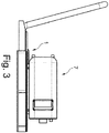
- Fig. 3 shows an object 7 with the holding plate 6 is screwed.
- Fig. 4 An object 7 is shown, which is clamped to the holding plate 6, in particular to the fastening device 14 designed as elongated holes with different diameters.
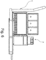
- Fig. 5 and 6 show the in Fig. 1 illustrated adapter 1 and in Fig. 1 shown object 7 in the state not installed in the vehicle. Because the object 7 is firmly connected to the adapter 1, the entire unit comprising the object 7 and the adapter 1 can be carried well by one person, in particular without the object 7 slipping relative to the adapter 1, for example. As a result, the object can be easily installed in the vehicle and removed from the vehicle.
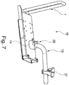
- Fig. 7 shows a laptop holder 16, which comprises the adapter 1 and a laptop holder 15 attached to it.
- the laptop holder 15 is fastened to the fastening device 14.
- the laptop holder 15 is screwed to the adapter 1.
- the laptop holder 15 could also be jammed, welded, or the like.
- Fig. 8 shows a measuring device fastening device 18, which comprises the adapter 1 and an object 7 attached thereto in the form of measuring devices.
- the measuring devices are fastened to the fastening device 14, in the exemplary embodiment jammed. Alternatively, screwing, welding, or the like can be considered.
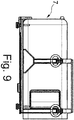
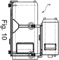
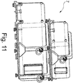
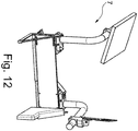
- the 9 to 12 show various embodiments of objects 7 that can be attached to the adapter 1. These exemplary embodiments are only a small subset of objects that can be fastened to the adapter 1.
- Fig. 9 shows an example as item 7 a box.
- Fig. 10 and 11 exemplarily show as boxes 7 two boxes that are arranged one above the other.
- Fig. 12 shows an example of the subject of plates on which, for example, a laptop, writing utensils, measuring technology or the like can be arranged and attached.
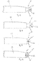
- the 13 to 16 show exemplary embodiments of the locking device 5.
- the locking device 5 comprises a lower locking finger 20 and an upper locking finger 21.
- the first position shown latch the locking fingers 20, 21 appropriately with the holder.
- the bracket is in 13 to 16 designed as a metal eyelet 22.
- In one in Fig. 14 Second position shown expose the locking fingers 20, 21 expediently the holder.
- the adapter 1 can thus be removed from the vehicle.
- the locking fingers 20, 21 are designed as claws, which can be pivoted towards and away from one another in particular.
- Locking fingers 20 ', 21' shown differ from those in FIGS 13 and 14 locking fingers 20, 21 shown by the geometric shape.
- the locking fingers 20, 21 shown are essentially straight, that is to say approximately linear, whereas the ones shown in FIGS Fig. 15 locking fingers 20 ', 21' shown are curved.
- the curvature expediently runs such that the curvature of the latching fingers 20 ', 21' runs in the direction of the metal eyelet 22.
- the 13 to 15 illustrated locking fingers 20, 21, 20 ', 21' can be referred to as claws.
- the claws can be moved towards and away from one another, in particular the claws can be pivoted.
- a joint in particular a hinge joint or the like, is expediently provided, about which the claws can be pivoted.
- the joint expediently connects the claws and the locking arm 19. The claws can be locked and thus form the locking device 5, 5 '.
- locking fingers 20 ", 21" are designed like pliers.
- the pliers are particularly rotary movable. The pliers can be locked and thus form the locking device 5 ".
- the claws or the tongs grip around the holder at least partially, in particular completely, in the first position. It can be expedient that only one of the two locking fingers 20, 20 ', 20 "is pivotable and / or rotatable, whereas in particular the other of the two locking fingers is fixed.
- the adapter 1 comprises an in Fig. 17 Floor support 24 shown.
- the floor support 24 is arranged on the holding plate 6, on the seat plate 17, on the holding bracket 13, or on one or on both latching arms 19, in particular firmly and particularly advantageously non-rotatably connected.
- the floor support 24 is arranged on the end face, in particular on the end face of the adapter 1 facing away from the latching device 5.
- the floor support 24 extends to in Fig. 17 Vehicle floor 23 shown schematically in the interior of the vehicle.
- the floor support 24 prevents the measuring device holder from immersing into the vehicle seat 2 together with the measuring devices and thus moving the measuring devices translationally and / or rotationally in the direction of the vehicle floor.
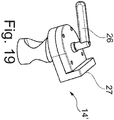
- the Fig. 18 and 19th show a second fastening device 14 'in the form of a ball joint 25.
- the ball joint 25 comprises a quick release 26 which fixes the ball joint 25 so that the joint is fixed.
- bracket 27 for the object 7, in particular a laptop, measuring device, or the like attached at the ball joint 25 .
- the holder 27 is designed as a stop against which the object 7 can rest.
- the bracket 27 can also be used as in Fig. 7 shown recording can be carried out, the object 7 can be firmly connected, for example jammed, screwed or the like.
- the holder 27 shown is expediently horizontally adjustable due to the ball joint 25.
- the holder 27 can also be aligned in a plane outside the horizontal, which, for example, enables the object 7, in particular the laptop, to be operated comfortably.
- the seat 3 is usually slightly inclined in the vehicle, the ball joint 25 can compensate for the inclination on the object 7 relative to the direction of travel.
- the object 7 can be aligned almost arbitrarily, so that the object 7 can be operated or used.
Landscapes
- Engineering & Computer Science (AREA)
- Mechanical Engineering (AREA)
- Fittings On The Vehicle Exterior For Carrying Loads, And Devices For Holding Or Mounting Articles (AREA)
- Seats For Vehicles (AREA)
Applications Claiming Priority (1)
| Application Number | Priority Date | Filing Date | Title |
|---|---|---|---|
| DE202019100463.0U DE202019100463U1 (de) | 2019-01-25 | 2019-01-25 | Adapter für ein Kraftfahrzeug |
Publications (2)
| Publication Number | Publication Date |
|---|---|
| EP3686061A1 true EP3686061A1 (fr) | 2020-07-29 |
| EP3686061B1 EP3686061B1 (fr) | 2022-01-12 |
Family
ID=67224071
Family Applications (1)
| Application Number | Title | Priority Date | Filing Date |
|---|---|---|---|
| EP20153323.9A Active EP3686061B1 (fr) | 2019-01-25 | 2020-01-23 | Adaptateur pour un véhicule automobile |
Country Status (2)
| Country | Link |
|---|---|
| EP (1) | EP3686061B1 (fr) |
| DE (1) | DE202019100463U1 (fr) |
Families Citing this family (5)
| Publication number | Priority date | Publication date | Assignee | Title |
|---|---|---|---|---|
| DE202024106250U1 (de) | 2024-07-01 | 2024-12-19 | Sarp Feinmechanik Gmbh | Adapter für ein Kraftfahrzeug |
| EP4674692A3 (fr) | 2024-07-01 | 2026-03-18 | SARP Feinmechanik GmbH | Adaptateur pour un véhicule automobile |
| EP4674691A3 (fr) | 2024-07-01 | 2026-03-18 | SARP Feinmechanik GmbH | Système de transport pour système prêt à l'emploi de mesure et de données dans des véhicules à moteur |
| EP4696561A1 (fr) | 2024-07-01 | 2026-02-18 | SARP Feinmechanik GmbH | Adaptateur pour un véhicule automobile |
| DE202024106248U1 (de) | 2024-07-01 | 2024-11-13 | Sarp Feinmechanik Gmbh | Adapter für ein Kraftfahrzeug |
Citations (9)
| Publication number | Priority date | Publication date | Assignee | Title |
|---|---|---|---|---|
| DE9113078U1 (de) * | 1991-10-21 | 1993-02-25 | Friedl, Nikolaus, 8031 Weßling | Befestigungsvorrichtung für einen Gegenstand auf einem Fahrzeugsitz |
| DE19744978A1 (de) * | 1997-10-14 | 1999-04-15 | Van Riesen Gmbh U Co Kg | Adapter |
| WO2004002773A1 (fr) * | 2002-07-01 | 2004-01-08 | Fair - S.R.L. | Bâti de fixation et dispositif de retenue avec bâti de fixation |
| DE102009058892A1 (de) * | 2009-12-18 | 2010-07-29 | Daimler Ag | Stauraumvorrichtung |
| JP2014061773A (ja) * | 2012-09-21 | 2014-04-10 | Takata Corp | 車載保持装置、車載保持システム、及び保持方法 |
| CN205395837U (zh) * | 2016-03-10 | 2016-07-27 | 宁波贝维尔婴童用品制造有限公司 | 一种儿童安全座椅及其isofix连接组件 |
| WO2016116610A1 (fr) * | 2015-01-23 | 2016-07-28 | Wolfgang Nickel | Dispositif de réception |
| EP3132975A1 (fr) * | 2015-08-17 | 2017-02-22 | Adolf Würth GmbH & Co. KG | Dispositif de montage d'un dispositif adaptateur pour fixer des receptacles sur un siege de vehicule automobile |
| EP3387900A1 (fr) * | 2017-04-13 | 2018-10-17 | DOGSTYLER Soest GmbH | Dispositif de retenue des articles à transporter pour un habitacle d'un vehicule automobile |
Family Cites Families (5)
| Publication number | Priority date | Publication date | Assignee | Title |
|---|---|---|---|---|
| DE10319404A1 (de) * | 2003-04-29 | 2004-11-18 | Voigtländer, Helga Maria | Vorrichtung zum gesicherten Transport von Gegenständen mit Fahrzeugen |
| DE10354703B4 (de) * | 2003-11-22 | 2016-04-07 | Audi Ag | Adapterplatte |
| DE202006007172U1 (de) * | 2006-05-03 | 2007-09-13 | Waeco International Gmbh | Adapter zum Befestigen eines tragbaren Kühlbehälters an einer Verankerungsvorrichtung an einem Sitz in einem Kraftfahrzeug sowie Kühlbehälter |
| DE102006023948B4 (de) * | 2006-05-17 | 2015-09-03 | Stefanie Schanen | Transportbehältersicherungssystem |
| DE102014100835A1 (de) * | 2014-01-24 | 2015-07-30 | Dr. Ing. H.C. F. Porsche Aktiengesellschaft | Mobiler Transportbehälter |
-
2019
- 2019-01-25 DE DE202019100463.0U patent/DE202019100463U1/de active Active
-
2020
- 2020-01-23 EP EP20153323.9A patent/EP3686061B1/fr active Active
Patent Citations (9)
| Publication number | Priority date | Publication date | Assignee | Title |
|---|---|---|---|---|
| DE9113078U1 (de) * | 1991-10-21 | 1993-02-25 | Friedl, Nikolaus, 8031 Weßling | Befestigungsvorrichtung für einen Gegenstand auf einem Fahrzeugsitz |
| DE19744978A1 (de) * | 1997-10-14 | 1999-04-15 | Van Riesen Gmbh U Co Kg | Adapter |
| WO2004002773A1 (fr) * | 2002-07-01 | 2004-01-08 | Fair - S.R.L. | Bâti de fixation et dispositif de retenue avec bâti de fixation |
| DE102009058892A1 (de) * | 2009-12-18 | 2010-07-29 | Daimler Ag | Stauraumvorrichtung |
| JP2014061773A (ja) * | 2012-09-21 | 2014-04-10 | Takata Corp | 車載保持装置、車載保持システム、及び保持方法 |
| WO2016116610A1 (fr) * | 2015-01-23 | 2016-07-28 | Wolfgang Nickel | Dispositif de réception |
| EP3132975A1 (fr) * | 2015-08-17 | 2017-02-22 | Adolf Würth GmbH & Co. KG | Dispositif de montage d'un dispositif adaptateur pour fixer des receptacles sur un siege de vehicule automobile |
| CN205395837U (zh) * | 2016-03-10 | 2016-07-27 | 宁波贝维尔婴童用品制造有限公司 | 一种儿童安全座椅及其isofix连接组件 |
| EP3387900A1 (fr) * | 2017-04-13 | 2018-10-17 | DOGSTYLER Soest GmbH | Dispositif de retenue des articles à transporter pour un habitacle d'un vehicule automobile |
Also Published As
| Publication number | Publication date |
|---|---|
| EP3686061B1 (fr) | 2022-01-12 |
| DE202019100463U9 (de) | 2024-08-22 |
| DE202019100463U1 (de) | 2019-06-25 |
Similar Documents
| Publication | Publication Date | Title |
|---|---|---|
| EP3686061B1 (fr) | Adaptateur pour un véhicule automobile | |
| DE69619394T2 (de) | Transportgestell für ein mantelgeblase eines flugzeugmotors | |
| EP2445789B1 (fr) | Element de verrouillage | |
| DE60200799T2 (de) | Rettungsfahrzeug | |
| DE2120392A1 (de) | Vorrichtung für den Fahrzeugtransport in einem Container | |
| DE102013108807B4 (de) | Befestigungsvorrichtung für Fahrzeugeinrichtungen | |
| DE69200173T2 (de) | Vorrichtung zum Befestigen eines Gegenstandes auf einem Transportträger, insbesondere Vorrichtung zum Verriegeln eines Brennstabbündels in einem Transportbehälter. | |
| EP0737601B1 (fr) | Dispositif pour éviter le glissement des objets transportés sur des plate-formes de charge de véhicules | |
| DE60119126T2 (de) | Vorrichtung zum festklemmen und transportieren flacher güter | |
| DE102018220377A1 (de) | Fahrzeug, Fahrzeugsystem und Verfahren zum Betreiben eines Fahrzeugsystems | |
| EP0939005A1 (fr) | Dispositif pour fixer des articles dans le compartiment à bagages d'un véhicule | |
| EP0446388B1 (fr) | Dispositif de transport pour conteneurs interchangeables ainsi que dispositif de fixation pour conteneur interchangeable disposé sur un véhicule de transport | |
| DE19804771C2 (de) | Verriegelungsvorrichtung für Container-Transportfahrzeuge | |
| EP2623375B1 (fr) | Support de toit | |
| DE3136956C2 (fr) | ||
| DE2944102C2 (de) | Langholzträger | |
| DE3423610A1 (de) | Wahlweise nach unten oder oben zu oeffnende hecktuer fuer kraftfahrzeuge | |
| DE102009060366A1 (de) | Lastenträger | |
| DE102022127514A1 (de) | Kraftfahrzeug mit einer Auszugsvorrichtung für eine Transporteinrichtung und Verfahren zum Betreiben eines Kraftfahrzeugs | |
| DE3118504C2 (de) | Transport- und Haltevorrichtung für ein Fahrzeugersatzrad | |
| EP3587181B1 (fr) | Véhicule de transport | |
| DE102021103039A1 (de) | Anhängerkupplungsadapter zur Befestigung an einem Stützschild | |
| EP4559743A1 (fr) | Siège de véhicule doté d'un dispositif de réglage longitudinal | |
| DE60307330T2 (de) | Seitliches Fahrschutzsystem | |
| DE29506922U1 (de) | Vorrichtung zum rutschfreien Transport von Gegenständen auf Ladeflächen von Kraftfahrzeugen |
Legal Events
| Date | Code | Title | Description |
|---|---|---|---|
| PUAI | Public reference made under article 153(3) epc to a published international application that has entered the european phase |
Free format text: ORIGINAL CODE: 0009012 |
|
| STAA | Information on the status of an ep patent application or granted ep patent |
Free format text: STATUS: THE APPLICATION HAS BEEN PUBLISHED |
|
| AK | Designated contracting states |
Kind code of ref document: A1 Designated state(s): AL AT BE BG CH CY CZ DE DK EE ES FI FR GB GR HR HU IE IS IT LI LT LU LV MC MK MT NL NO PL PT RO RS SE SI SK SM TR |
|
| AX | Request for extension of the european patent |
Extension state: BA ME |
|
| STAA | Information on the status of an ep patent application or granted ep patent |
Free format text: STATUS: REQUEST FOR EXAMINATION WAS MADE |
|
| 17P | Request for examination filed |
Effective date: 20210128 |
|
| RBV | Designated contracting states (corrected) |
Designated state(s): AL AT BE BG CH CY CZ DE DK EE ES FI FR GB GR HR HU IE IS IT LI LT LU LV MC MK MT NL NO PL PT RO RS SE SI SK SM TR |
|
| GRAP | Despatch of communication of intention to grant a patent |
Free format text: ORIGINAL CODE: EPIDOSNIGR1 |
|
| STAA | Information on the status of an ep patent application or granted ep patent |
Free format text: STATUS: GRANT OF PATENT IS INTENDED |
|
| RIC1 | Information provided on ipc code assigned before grant |
Ipc: B60R 7/04 20060101AFI20210304BHEP |
|
| INTG | Intention to grant announced |
Effective date: 20210318 |
|
| GRAJ | Information related to disapproval of communication of intention to grant by the applicant or resumption of examination proceedings by the epo deleted |
Free format text: ORIGINAL CODE: EPIDOSDIGR1 |
|
| STAA | Information on the status of an ep patent application or granted ep patent |
Free format text: STATUS: REQUEST FOR EXAMINATION WAS MADE |
|
| GRAP | Despatch of communication of intention to grant a patent |
Free format text: ORIGINAL CODE: EPIDOSNIGR1 |
|
| STAA | Information on the status of an ep patent application or granted ep patent |
Free format text: STATUS: GRANT OF PATENT IS INTENDED |
|
| INTC | Intention to grant announced (deleted) | ||
| INTG | Intention to grant announced |
Effective date: 20210901 |
|
| GRAS | Grant fee paid |
Free format text: ORIGINAL CODE: EPIDOSNIGR3 |
|
| GRAA | (expected) grant |
Free format text: ORIGINAL CODE: 0009210 |
|
| STAA | Information on the status of an ep patent application or granted ep patent |
Free format text: STATUS: THE PATENT HAS BEEN GRANTED |
|
| AK | Designated contracting states |
Kind code of ref document: B1 Designated state(s): AL AT BE BG CH CY CZ DE DK EE ES FI FR GB GR HR HU IE IS IT LI LT LU LV MC MK MT NL NO PL PT RO RS SE SI SK SM TR |
|
| REG | Reference to a national code |
Ref country code: GB Ref legal event code: FG4D Free format text: NOT ENGLISH |
|
| REG | Reference to a national code |
Ref country code: CH Ref legal event code: EP |
|
| REG | Reference to a national code |
Ref country code: DE Ref legal event code: R096 Ref document number: 502020000527 Country of ref document: DE |
|
| REG | Reference to a national code |
Ref country code: IE Ref legal event code: FG4D Free format text: LANGUAGE OF EP DOCUMENT: GERMAN |
|
| REG | Reference to a national code |
Ref country code: AT Ref legal event code: REF Ref document number: 1462159 Country of ref document: AT Kind code of ref document: T Effective date: 20220215 |
|
| REG | Reference to a national code |
Ref country code: LT Ref legal event code: MG9D |
|
| PG25 | Lapsed in a contracting state [announced via postgrant information from national office to epo] |
Ref country code: NL Free format text: LAPSE BECAUSE OF FAILURE TO SUBMIT A TRANSLATION OF THE DESCRIPTION OR TO PAY THE FEE WITHIN THE PRESCRIBED TIME-LIMIT Effective date: 20220112 |
|
| PG25 | Lapsed in a contracting state [announced via postgrant information from national office to epo] |
Ref country code: SE Free format text: LAPSE BECAUSE OF FAILURE TO SUBMIT A TRANSLATION OF THE DESCRIPTION OR TO PAY THE FEE WITHIN THE PRESCRIBED TIME-LIMIT Effective date: 20220112 Ref country code: RS Free format text: LAPSE BECAUSE OF FAILURE TO SUBMIT A TRANSLATION OF THE DESCRIPTION OR TO PAY THE FEE WITHIN THE PRESCRIBED TIME-LIMIT Effective date: 20220112 Ref country code: PT Free format text: LAPSE BECAUSE OF FAILURE TO SUBMIT A TRANSLATION OF THE DESCRIPTION OR TO PAY THE FEE WITHIN THE PRESCRIBED TIME-LIMIT Effective date: 20220512 Ref country code: NO Free format text: LAPSE BECAUSE OF FAILURE TO SUBMIT A TRANSLATION OF THE DESCRIPTION OR TO PAY THE FEE WITHIN THE PRESCRIBED TIME-LIMIT Effective date: 20220412 Ref country code: LT Free format text: LAPSE BECAUSE OF FAILURE TO SUBMIT A TRANSLATION OF THE DESCRIPTION OR TO PAY THE FEE WITHIN THE PRESCRIBED TIME-LIMIT Effective date: 20220112 Ref country code: HR Free format text: LAPSE BECAUSE OF FAILURE TO SUBMIT A TRANSLATION OF THE DESCRIPTION OR TO PAY THE FEE WITHIN THE PRESCRIBED TIME-LIMIT Effective date: 20220112 Ref country code: ES Free format text: LAPSE BECAUSE OF FAILURE TO SUBMIT A TRANSLATION OF THE DESCRIPTION OR TO PAY THE FEE WITHIN THE PRESCRIBED TIME-LIMIT Effective date: 20220112 Ref country code: BG Free format text: LAPSE BECAUSE OF FAILURE TO SUBMIT A TRANSLATION OF THE DESCRIPTION OR TO PAY THE FEE WITHIN THE PRESCRIBED TIME-LIMIT Effective date: 20220412 |
|
| PG25 | Lapsed in a contracting state [announced via postgrant information from national office to epo] |
Ref country code: PL Free format text: LAPSE BECAUSE OF FAILURE TO SUBMIT A TRANSLATION OF THE DESCRIPTION OR TO PAY THE FEE WITHIN THE PRESCRIBED TIME-LIMIT Effective date: 20220112 Ref country code: LV Free format text: LAPSE BECAUSE OF FAILURE TO SUBMIT A TRANSLATION OF THE DESCRIPTION OR TO PAY THE FEE WITHIN THE PRESCRIBED TIME-LIMIT Effective date: 20220112 Ref country code: GR Free format text: LAPSE BECAUSE OF FAILURE TO SUBMIT A TRANSLATION OF THE DESCRIPTION OR TO PAY THE FEE WITHIN THE PRESCRIBED TIME-LIMIT Effective date: 20220413 Ref country code: FI Free format text: LAPSE BECAUSE OF FAILURE TO SUBMIT A TRANSLATION OF THE DESCRIPTION OR TO PAY THE FEE WITHIN THE PRESCRIBED TIME-LIMIT Effective date: 20220112 |
|
| PG25 | Lapsed in a contracting state [announced via postgrant information from national office to epo] |
Ref country code: IS Free format text: LAPSE BECAUSE OF FAILURE TO SUBMIT A TRANSLATION OF THE DESCRIPTION OR TO PAY THE FEE WITHIN THE PRESCRIBED TIME-LIMIT Effective date: 20220512 |
|
| REG | Reference to a national code |
Ref country code: BE Ref legal event code: MM Effective date: 20220131 |
|
| REG | Reference to a national code |
Ref country code: DE Ref legal event code: R097 Ref document number: 502020000527 Country of ref document: DE |
|
| PG25 | Lapsed in a contracting state [announced via postgrant information from national office to epo] |
Ref country code: SM Free format text: LAPSE BECAUSE OF FAILURE TO SUBMIT A TRANSLATION OF THE DESCRIPTION OR TO PAY THE FEE WITHIN THE PRESCRIBED TIME-LIMIT Effective date: 20220112 Ref country code: SK Free format text: LAPSE BECAUSE OF FAILURE TO SUBMIT A TRANSLATION OF THE DESCRIPTION OR TO PAY THE FEE WITHIN THE PRESCRIBED TIME-LIMIT Effective date: 20220112 Ref country code: RO Free format text: LAPSE BECAUSE OF FAILURE TO SUBMIT A TRANSLATION OF THE DESCRIPTION OR TO PAY THE FEE WITHIN THE PRESCRIBED TIME-LIMIT Effective date: 20220112 Ref country code: MC Free format text: LAPSE BECAUSE OF FAILURE TO SUBMIT A TRANSLATION OF THE DESCRIPTION OR TO PAY THE FEE WITHIN THE PRESCRIBED TIME-LIMIT Effective date: 20220112 Ref country code: LU Free format text: LAPSE BECAUSE OF NON-PAYMENT OF DUE FEES Effective date: 20220123 Ref country code: EE Free format text: LAPSE BECAUSE OF FAILURE TO SUBMIT A TRANSLATION OF THE DESCRIPTION OR TO PAY THE FEE WITHIN THE PRESCRIBED TIME-LIMIT Effective date: 20220112 Ref country code: DK Free format text: LAPSE BECAUSE OF FAILURE TO SUBMIT A TRANSLATION OF THE DESCRIPTION OR TO PAY THE FEE WITHIN THE PRESCRIBED TIME-LIMIT Effective date: 20220112 Ref country code: CZ Free format text: LAPSE BECAUSE OF FAILURE TO SUBMIT A TRANSLATION OF THE DESCRIPTION OR TO PAY THE FEE WITHIN THE PRESCRIBED TIME-LIMIT Effective date: 20220112 |
|
| PLBE | No opposition filed within time limit |
Free format text: ORIGINAL CODE: 0009261 |
|
| STAA | Information on the status of an ep patent application or granted ep patent |
Free format text: STATUS: NO OPPOSITION FILED WITHIN TIME LIMIT |
|
| PG25 | Lapsed in a contracting state [announced via postgrant information from national office to epo] |
Ref country code: BE Free format text: LAPSE BECAUSE OF NON-PAYMENT OF DUE FEES Effective date: 20220131 Ref country code: AL Free format text: LAPSE BECAUSE OF FAILURE TO SUBMIT A TRANSLATION OF THE DESCRIPTION OR TO PAY THE FEE WITHIN THE PRESCRIBED TIME-LIMIT Effective date: 20220112 |
|
| 26N | No opposition filed |
Effective date: 20221013 |
|
| PG25 | Lapsed in a contracting state [announced via postgrant information from national office to epo] |
Ref country code: IE Free format text: LAPSE BECAUSE OF NON-PAYMENT OF DUE FEES Effective date: 20220123 |
|
| PG25 | Lapsed in a contracting state [announced via postgrant information from national office to epo] |
Ref country code: SI Free format text: LAPSE BECAUSE OF FAILURE TO SUBMIT A TRANSLATION OF THE DESCRIPTION OR TO PAY THE FEE WITHIN THE PRESCRIBED TIME-LIMIT Effective date: 20220112 |
|
| PG25 | Lapsed in a contracting state [announced via postgrant information from national office to epo] |
Ref country code: IT Free format text: LAPSE BECAUSE OF FAILURE TO SUBMIT A TRANSLATION OF THE DESCRIPTION OR TO PAY THE FEE WITHIN THE PRESCRIBED TIME-LIMIT Effective date: 20220112 |
|
| REG | Reference to a national code |
Ref country code: CH Ref legal event code: PL |
|
| PG25 | Lapsed in a contracting state [announced via postgrant information from national office to epo] |
Ref country code: LI Free format text: LAPSE BECAUSE OF NON-PAYMENT OF DUE FEES Effective date: 20230131 Ref country code: CH Free format text: LAPSE BECAUSE OF NON-PAYMENT OF DUE FEES Effective date: 20230131 |
|
| PG25 | Lapsed in a contracting state [announced via postgrant information from national office to epo] |
Ref country code: MK Free format text: LAPSE BECAUSE OF FAILURE TO SUBMIT A TRANSLATION OF THE DESCRIPTION OR TO PAY THE FEE WITHIN THE PRESCRIBED TIME-LIMIT Effective date: 20220112 Ref country code: CY Free format text: LAPSE BECAUSE OF FAILURE TO SUBMIT A TRANSLATION OF THE DESCRIPTION OR TO PAY THE FEE WITHIN THE PRESCRIBED TIME-LIMIT Effective date: 20220112 |
|
| PG25 | Lapsed in a contracting state [announced via postgrant information from national office to epo] |
Ref country code: HU Free format text: LAPSE BECAUSE OF FAILURE TO SUBMIT A TRANSLATION OF THE DESCRIPTION OR TO PAY THE FEE WITHIN THE PRESCRIBED TIME-LIMIT; INVALID AB INITIO Effective date: 20200123 |
|
| PG25 | Lapsed in a contracting state [announced via postgrant information from national office to epo] |
Ref country code: MT Free format text: LAPSE BECAUSE OF FAILURE TO SUBMIT A TRANSLATION OF THE DESCRIPTION OR TO PAY THE FEE WITHIN THE PRESCRIBED TIME-LIMIT Effective date: 20220112 |
|
| PG25 | Lapsed in a contracting state [announced via postgrant information from national office to epo] |
Ref country code: TR Free format text: LAPSE BECAUSE OF FAILURE TO SUBMIT A TRANSLATION OF THE DESCRIPTION OR TO PAY THE FEE WITHIN THE PRESCRIBED TIME-LIMIT Effective date: 20220112 |
|
| PGFP | Annual fee paid to national office [announced via postgrant information from national office to epo] |
Ref country code: GB Payment date: 20260122 Year of fee payment: 7 |
|
| PGFP | Annual fee paid to national office [announced via postgrant information from national office to epo] |
Ref country code: DE Payment date: 20260120 Year of fee payment: 7 |
|
| PGFP | Annual fee paid to national office [announced via postgrant information from national office to epo] |
Ref country code: AT Payment date: 20260119 Year of fee payment: 7 |
|
| PGFP | Annual fee paid to national office [announced via postgrant information from national office to epo] |
Ref country code: FR Payment date: 20260121 Year of fee payment: 7 |