EP3686432A1 - Pompe à vide - Google Patents
Pompe à vide Download PDFInfo
- Publication number
- EP3686432A1 EP3686432A1 EP20166248.3A EP20166248A EP3686432A1 EP 3686432 A1 EP3686432 A1 EP 3686432A1 EP 20166248 A EP20166248 A EP 20166248A EP 3686432 A1 EP3686432 A1 EP 3686432A1
- Authority
- EP
- European Patent Office
- Prior art keywords
- vacuum pump
- pump
- evaluation unit
- vibration data
- vibration
- Prior art date
- Legal status (The legal status is an assumption and is not a legal conclusion. Google has not performed a legal analysis and makes no representation as to the accuracy of the status listed.)
- Granted
Links
Images


Classifications
-
- F—MECHANICAL ENGINEERING; LIGHTING; HEATING; WEAPONS; BLASTING
- F04—POSITIVE - DISPLACEMENT MACHINES FOR LIQUIDS; PUMPS FOR LIQUIDS OR ELASTIC FLUIDS
- F04C—ROTARY-PISTON, OR OSCILLATING-PISTON, POSITIVE-DISPLACEMENT MACHINES FOR LIQUIDS; ROTARY-PISTON, OR OSCILLATING-PISTON, POSITIVE-DISPLACEMENT PUMPS
- F04C25/00—Adaptations of pumps for special use of pumps for elastic fluids
- F04C25/02—Adaptations of pumps for special use of pumps for elastic fluids for producing high vacuum
-
- F—MECHANICAL ENGINEERING; LIGHTING; HEATING; WEAPONS; BLASTING
- F04—POSITIVE - DISPLACEMENT MACHINES FOR LIQUIDS; PUMPS FOR LIQUIDS OR ELASTIC FLUIDS
- F04C—ROTARY-PISTON, OR OSCILLATING-PISTON, POSITIVE-DISPLACEMENT MACHINES FOR LIQUIDS; ROTARY-PISTON, OR OSCILLATING-PISTON, POSITIVE-DISPLACEMENT PUMPS
- F04C18/00—Rotary-piston pumps specially adapted for elastic fluids
- F04C18/08—Rotary-piston pumps specially adapted for elastic fluids of intermeshing-engagement type, i.e. with engagement of co-operating members similar to that of toothed gearing
- F04C18/12—Rotary-piston pumps specially adapted for elastic fluids of intermeshing-engagement type, i.e. with engagement of co-operating members similar to that of toothed gearing of other than internal-axis type
- F04C18/126—Rotary-piston pumps specially adapted for elastic fluids of intermeshing-engagement type, i.e. with engagement of co-operating members similar to that of toothed gearing of other than internal-axis type with radially from the rotor body extending elements, not necessarily co-operating with corresponding recesses in the other rotor, e.g. lobes, Roots type
-
- F—MECHANICAL ENGINEERING; LIGHTING; HEATING; WEAPONS; BLASTING
- F04—POSITIVE - DISPLACEMENT MACHINES FOR LIQUIDS; PUMPS FOR LIQUIDS OR ELASTIC FLUIDS
- F04C—ROTARY-PISTON, OR OSCILLATING-PISTON, POSITIVE-DISPLACEMENT MACHINES FOR LIQUIDS; ROTARY-PISTON, OR OSCILLATING-PISTON, POSITIVE-DISPLACEMENT PUMPS
- F04C18/00—Rotary-piston pumps specially adapted for elastic fluids
- F04C18/08—Rotary-piston pumps specially adapted for elastic fluids of intermeshing-engagement type, i.e. with engagement of co-operating members similar to that of toothed gearing
- F04C18/12—Rotary-piston pumps specially adapted for elastic fluids of intermeshing-engagement type, i.e. with engagement of co-operating members similar to that of toothed gearing of other than internal-axis type
- F04C18/14—Rotary-piston pumps specially adapted for elastic fluids of intermeshing-engagement type, i.e. with engagement of co-operating members similar to that of toothed gearing of other than internal-axis type with toothed rotary pistons
- F04C18/16—Rotary-piston pumps specially adapted for elastic fluids of intermeshing-engagement type, i.e. with engagement of co-operating members similar to that of toothed gearing of other than internal-axis type with toothed rotary pistons with helical teeth, e.g. chevron-shaped, screw type
-
- F—MECHANICAL ENGINEERING; LIGHTING; HEATING; WEAPONS; BLASTING
- F04—POSITIVE - DISPLACEMENT MACHINES FOR LIQUIDS; PUMPS FOR LIQUIDS OR ELASTIC FLUIDS
- F04C—ROTARY-PISTON, OR OSCILLATING-PISTON, POSITIVE-DISPLACEMENT MACHINES FOR LIQUIDS; ROTARY-PISTON, OR OSCILLATING-PISTON, POSITIVE-DISPLACEMENT PUMPS
- F04C28/00—Control of, monitoring of, or safety arrangements for, pumps or pumping installations specially adapted for elastic fluids
- F04C28/06—Control of, monitoring of, or safety arrangements for, pumps or pumping installations specially adapted for elastic fluids specially adapted for stopping, starting, idling or no-load operation
-
- F—MECHANICAL ENGINEERING; LIGHTING; HEATING; WEAPONS; BLASTING
- F04—POSITIVE - DISPLACEMENT MACHINES FOR LIQUIDS; PUMPS FOR LIQUIDS OR ELASTIC FLUIDS
- F04C—ROTARY-PISTON, OR OSCILLATING-PISTON, POSITIVE-DISPLACEMENT MACHINES FOR LIQUIDS; ROTARY-PISTON, OR OSCILLATING-PISTON, POSITIVE-DISPLACEMENT PUMPS
- F04C2240/00—Components
- F04C2240/80—Other components
- F04C2240/81—Sensor, e.g. electronic sensor for control or monitoring
-
- F—MECHANICAL ENGINEERING; LIGHTING; HEATING; WEAPONS; BLASTING
- F04—POSITIVE - DISPLACEMENT MACHINES FOR LIQUIDS; PUMPS FOR LIQUIDS OR ELASTIC FLUIDS
- F04C—ROTARY-PISTON, OR OSCILLATING-PISTON, POSITIVE-DISPLACEMENT MACHINES FOR LIQUIDS; ROTARY-PISTON, OR OSCILLATING-PISTON, POSITIVE-DISPLACEMENT PUMPS
- F04C2270/00—Control; Monitoring or safety arrangements
- F04C2270/12—Vibration
- F04C2270/125—Controlled or regulated
Definitions
- the invention relates to a vacuum pump, which is in particular a Roots pump or screw pump.
- the vacuum pump has pump-active elements which can be driven to perform a working movement and which transport a gas to be pumped from an inlet to an outlet of the vacuum pump.
- Vacuum systems typically comprise one or more vacuum pumps, for example at least one vacuum pump for the rough vacuum range and at least one vacuum pump for the high vacuum range, and are usually designed for continuous operation. In many applications, the vacuum pumps in the vacuum system run continuously for several months or even years. In addition, downtimes between operating phases of the vacuum system are to be minimized as far as possible, and the maintenance of the vacuum pumps should take place within these relatively short downtimes.
- vibrations of vacuum pumps there is a connection between vibrations of vacuum pumps and their operating state or state of wear.
- a sudden failure of a vacuum pump can result from excessive vibrations or even noise.
- Such vibrations can be caused, for example, by an imbalance in a rotor of the vacuum pump and an increase in unbalance can cause an increase in the vibrations of the vacuum pump.
- Monitoring of vibrations of a vacuum pump has, however, hitherto not been provided in conventional vacuum systems and is consequently only carried out sporadically.
- vibrations of a vacuum pump are monitored in such cases with comparatively expensive external devices.
- An object of the invention is to provide a vacuum pump in which a possibly impending failure can be recognized at an early stage.
- the vacuum pump which is in particular a Roots pump or a screw pump, comprises pump-active elements which can be driven to perform a working movement and thereby transport a gas to be pumped from an inlet to an outlet of the vacuum pump. Furthermore, the vacuum pump comprises a vibration sensor, which records vibration data of the vacuum pump on the basis of the working movement of the pump-active elements, and an evaluation unit, which is designed to evaluate the vibration data.
- the vacuum pump according to the invention is characterized in that the vibration sensor and the evaluation unit for the vibration data that the vibration sensor records are essential components of the vacuum pump itself. Consequently, no expensive external devices are required for recording and evaluating the vibration data of the vacuum pump.
- the evaluation unit can either have a common one Form unit with the vibration sensor, for example in the form of a single electronic device, which can include both the vibration sensor and the evaluation unit, or be arranged externally.
- the evaluation unit like a control unit of the entire vacuum pump, can be arranged outside a housing of the vacuum pump and, like the control unit, can nevertheless form an essential component of the vacuum pump itself.
- the vibration sensor and the evaluation unit regardless of whether the evaluation unit is arranged inside or outside the housing of the vacuum pump, together with a control unit, are to be regarded as integral components of the vacuum pump.
- the internal or external arrangement of a control unit for the vacuum pump and the evaluation unit for the vibration data can depend, for example, on the available space for the vacuum pump. With an external arrangement of the evaluation unit, for example outside the housing of the vacuum pump, the evaluation unit can be integrated into the control unit of the vacuum pump. Regardless of whether the evaluation unit forms a common electronic device with the vibration sensor or is arranged externally, there is an electronic communication connection between the evaluation unit and the vibration sensor for transmitting the vibration data as signals from the vibration sensor to the evaluation unit.
- a potential impending failure of the vacuum pump can be recognized at an early stage on the basis of the evaluation of the vibration data, which is carried out by means of the evaluation unit. For example, if the intensity of the vibrations measured by the vibration sensor exceeds a certain threshold value due to an increased amplitude of the vibrations of the vacuum pump, this can be an indicator of a possible impending failure of the vacuum pump due to a malfunction of the pump-active elements. In one In such a case, ie if a possible impending failure of the vacuum pump can be recognized by the evaluation unit on the basis of the vibration data, the evaluation unit can generate an advisory signal which can be perceived by a user of the vacuum system, for example by means of a warning lamp or an audible signal.
- the evaluation unit Based on the evaluation of the vibration data by means of the evaluation unit, it is consequently possible to recognize and prevent an impending failure of the vacuum pump by providing a planned downtime for the vacuum pump for its maintenance. Based on the total operating time of the vacuum pump or vacuum system, the total downtime can be shortened by avoiding unforeseen failures of the vacuum pumps. Instead of an unforeseen failure, a "predictive maintenance" takes place instead by evaluating the vibration data and recognizing an impending failure. a planned downtime for the maintenance of the pump, which is usually shorter than the downtime after an unforeseen failure.
- the evaluation unit of the vacuum pump is also designed to determine a state of wear of the vacuum pump based on the vibration data.
- the evaluation unit can, for example, indicate that the vacuum pump is in a certain state of wear if the intensity of the vibrations, which are detected by the vibration sensor, exceeds a predetermined threshold value due to an increased amplitude of the vibrations of the vacuum pump.
- a predetermined threshold value can, for example, be assigned directly to a specific state of wear of the vacuum pump.
- the predefined threshold can be calibratable and based on empirical values, for example on the basis of vibration data which were recorded in the event of an actual failure of the vacuum pump. If the absolute amount of the vibration data is above the predetermined threshold value, the evaluation unit can in turn output an advisory signal that can be perceptible to a user of the vacuum system.
- the vibration data for determining the state of wear of the vacuum chamber can be recorded and stored periodically at predetermined time intervals, and the evaluation unit can compare the vibration data last recorded with the vibration data recorded and stored earlier. As soon as the evaluation unit detects a significant deviation between the last recorded vibration data and the previously stored vibration data, for example a significant increase in the amplitude of the vibrations or the absolute amount of the vibration data, the evaluation unit can in turn output an advisory signal that indicates a predefined, undesired state of wear of the vacuum pump .
- the notification signal can be output if, for example, the mean deviation between the vibration data last recorded and the vibration data stored earlier exceeds a further predetermined threshold value.
- the evaluation unit can alternatively or additionally access vibration data that have been recorded and stored for a large number of identical or similar vacuum pumps and are available, for example, in the form of a database.
- the evaluation unit can relate current vibration data of the vacuum pump, which are currently detected by the vibration sensor, to the stored vibration data from the database.
- the evaluation unit can include a neural network that can be learned from the database using the previously stored data, in order to use the vibration data currently detected by the vibration sensor to detect an undesirable state of wear of the vacuum pump at an early stage.
- the vibration sensor can comprise an acceleration sensor, which is in particular an acceleration sensor of a micro-electromechanical system (MEMS sensor).
- MEMS sensor micro-electromechanical system
- the acceleration sensor preferably detects the acceleration in at least two directions.
- one of the directions in which the acceleration sensor detects the acceleration is aligned with an axis of rotation of the pump-active elements of the vacuum pump. If the acceleration sensor can detect the acceleration in two or even three directions, this improves the reliability of the vibration sensor, since the detection of the vibration data is therefore not restricted to one spatial direction. In other words, the detection of the acceleration in two or three spatial directions reduces the probability that vibrations of the vacuum pump occur which cannot be detected by the vibration sensor.
- By aligning one of the directions in which the acceleration sensor detects the acceleration with the axis of rotation of the pump-active elements a change in the vibration data, which is specifically caused by the pump-active elements, can be detected. For example, with such an alignment of the acceleration sensor, an imbalance of the pump-active elements can be recognized at an early stage, since the vibration data which the acceleration sensor aligned with the axis of rotation of the pump-active elements detects are specific to the pump-active elements.
- the vibration sensor is arranged within a housing of the vacuum pump.
- the vibration sensor is thus fully integrated into the vacuum pump and protected from external influences within the housing.
- the distance between the vibration sensor and the pump-active elements within the housing can also be chosen to be as small as possible, so that the acquisition of the vibration data is improved due to the working movement of the pump-active elements.
- the vibration sensor can be directly coupled to the housing of the vacuum pump. If the pump-active elements cause undesired vibrations, these are usually transmitted to the housing of the vacuum pump. With a direct coupling of the vibration sensor to the housing of the vacuum pump, the vibration data of the vacuum pump can be recorded in a particularly simple and reliable manner due to the working movement of the pump-active elements.
- the vibration sensor can also be attached to an inner wall of the housing of the vacuum pump and can be directly coupled to it, so that the vibration sensor can simultaneously be arranged within the housing of the vacuum pump and can be directly coupled to it.
- the vibration sensor can be integrated in a circuit board of the vacuum pump.
- the circuit board is arranged in particular in an interior of the vacuum pump.
- the vibration sensor can, in particular, only represent a further component of an existing circuit board of the vacuum pump, so that the vibration sensor can be integrated into the vacuum pump in a simple and inexpensive manner. If the circuit board is arranged in the interior of the vacuum pump, the circuit board can also simultaneously represent a vacuum feedthrough.
- the circuit board is preferably integrated in a drive electronics of a drive motor of the vacuum pump.
- the circuit board can in particular be arranged in a so-called terminal box of the drive motor of the vacuum pump.
- the evaluation unit can be integrated in the circuit board of the vacuum pump.
- unused space within the vacuum pump for example in the terminal box of the drive motor, can be used to integrate the vibration sensor and / or the evaluation unit. If both the vibration sensor and the evaluation unit are arranged on the circuit board of the vacuum pump or are integrated in the latter, the vibration sensor and the evaluation unit form a particularly compact unit that outputs vibration data that has already been evaluated, for example by means of a signal that indicates the state of wear of the vacuum pump.
- the evaluation unit can also have an integrated processor which is designed to assign the vibration data to a state of wear of the vacuum pump.
- the vibration data is therefore fully evaluated in the integrated processor of the evaluation unit, which is also integrated in the circuit board of the vacuum pump.
- the evaluation unit can in turn form a compact unit together with the vibration sensor, even if it is attached to a section of the housing of the vacuum pump outside the circuit board.
- the vacuum pump has an interface for outputting the vibration data.
- the evaluation unit is preferably arranged outside a housing of the vacuum pump in order to receive the vibration data via the interface.
- This embodiment thus represents an alternative to integrating the evaluation unit into the circuit board of the vacuum pump.
- the arrangement of the evaluation unit outside the housing of the vacuum pump allows, for example, a flexible arrangement of the vibration sensor on or in the housing of the vacuum pump, so that the vibration data recorded by it only have to be made available to the evaluation unit via the interface.
- the vibration sensor and the evaluation unit with an integrated processor can be integrated in a circuit board of the vacuum pump, which is arranged, for example, in a terminal box of a drive motor within a housing of the vacuum pump, and an interface of the vacuum pump can be provided at the same time.
- the interface can be used to output the vibration data and also to output data that are evaluated by the evaluation unit and indicate a state of wear of the vacuum pump.
- the additional output of the original vibration data, which is recorded by means of the vibration sensor can additionally enable an external, redundant evaluation of the vibration data.
- the reliability of the evaluation unit can be checked and thus improved by a comparison with the output of the internal evaluation unit.
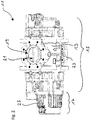
- Fig. 1 shows a vacuum pump 11 according to the invention in a schematic perspective view.
- the vacuum pump 11 is a Roots pump that can be used, for example, for the rough and fine vacuum range within a vacuum system.
- the vacuum pump 11 has a housing 13 which comprises a main section 15 and a motor section 17.
- the main section 15 and the motor section 17 are connected to one another by means of screws 18.
- the main section 15 of the housing 13 of the vacuum pump 11 has a suction flange 19, which serves as an inlet for a gas to be pumped, which is sucked in from a recipient, not shown.
- At least one further vacuum pump for example a turbomolecular pump (not shown), is usually arranged between the recipient and the vacuum pump 11 within a vacuum system.
- the vacuum pump 11 designed as a Roots pump requires a backing pump which is connected to the outlet 23 of the vacuum pump 11 and ejects against atmospheric pressure.
- the vacuum pump 11 is usually located in a vacuum system between a pump for the high vacuum range, for example a turbomolecular pump, and the backing pump that emits against atmospheric pressure.
- the vacuum pump 11 also has pump-active elements (not shown) in the form of Roots, which in an interior 21 (cf. Fig. 2 ) of the housing 13 are arranged.
- the pump-active elements are intended to transport the gas to be pumped from the inlet 19 to an outlet 23 of the vacuum pump 11.
- the active pump elements are in Fig. 2 can be seen within the intake flange 19.
- an electric motor not shown, which is arranged within the motor section 17, the pump-active elements are driven to a working movement. Due to this working movement of the pump-active elements, the entire vacuum pump 11 is set in oscillations, which transmit the pump-active elements to the housing 13 of the vacuum pump 11.
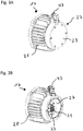
- FIG 3A shows a perspective detailed view of the motor section 17 of the vacuum pump 11.
- the motor section 17 has cooling fins 25 on its outer circumference, which are provided for cooling the electric motor, which is located in an interior of the motor section 17.
- the motor section 17 includes in an end section which is shown in FIG 3A and 3B is shown on the right, a terminal box 27, which in Figure 3A is closed by a cover 29, while the cover 29 in Figure 3B is removed.
- the motor section 17 has no cooling fins 25, since the terminal box 27 is provided for the electrical connections of the electric motor of the vacuum pump 11 and therefore does not require any cooling.
- the electric motor of the vacuum pump 11 can also be water-cooled.
- the motor section 17 has cast-in water pipes and does not require any cooling fins 25.
- connection elements 31 are arranged in the terminal box 27 of the motor section 17 and are provided for supplying the electric motor with electrical currents and voltages. Furthermore, the terminal box 27 comprises an earthing 33, which are attached to a housing wall 35 inside the terminal box 27, on which the connection elements 31 are also located.
- a circuit board 37 is also arranged, which is also attached to the housing wall or inner wall 35 of the terminal box 27.
- the circuit board 37 has a vibration sensor 39, which acts as an acceleration sensor a micro-electromechanical system (MEMS sensor) is formed.
- MEMS sensor micro-electromechanical system
- the vibration sensor 39 is in direct connection with the housing wall 35, ie there are no further elements between the vibration sensor 39 and the housing wall 35 in order to transmit vibrations of the housing 13 of the vacuum pump 11 as directly as possible to the vibration sensor 39.
- the circuit board 37 also has an evaluation unit 41 for the vibration sensor 39.
- the evaluation unit 41 comprises an integrated processor, with which the evaluation of vibration data takes place, which are recorded by means of the vibration sensor 39.
- the vibration sensor 39 and the evaluation unit 41 including the processor are thus in an electronic communication connection within the circuit board 37.
- the motor section 17 has an electrical connection 43 on its outside, to which a plug (not shown) can be attached.
- the electrical connection 43 is electrically connected both to the connection elements 31 for the electric motor of the vacuum pump 11 and to the evaluation unit 41 on the circuit board 37, in order to ensure the power supply of the electric motor and the circuit board 37 on the one hand and to establish a connection for signals from of the evaluation unit 41 are provided and represent an indicator of a state of wear of the vacuum pump 11.
- the vibration sensor 39 which is designed as a MEMS sensor, is able to measure an acceleration in all three spatial directions.
- the vibration sensor 39 thus detects vibrations in all three spatial directions.
- One of these spatial directions or axes is with an axis of rotation of the pump-active elements of the vacuum pump 11 (cf. Fig. 2 ) aligned. This makes it particularly easy to detect vibrations that occur due to the fact that the movement of the pump-active elements of an expected movement in normal operation the vacuum pump 11 deviates. This can be caused, for example, by an imbalance in the pump-active elements.
- the vibration data that are recorded by means of the vibration sensor 39 are evaluated by means of the evaluation unit 41 or by means of their processor, for example by comparing these vibration data with vibration data that were recorded at an earlier point in time and are stored in the evaluation unit 41. For example, the amplitude of the current and previous vibration data, averaged over a predetermined period of time, is compared. Alternatively, the amplitude of the recorded vibration data can also be compared with a predetermined threshold value, which is based on empirical values.
- the evaluation unit 41 If a significant deviation between the current vibration data and the stored vibration data acquired at an earlier point in time is determined or the amplitude of the vibration data lies above the predetermined threshold value, the evaluation unit 41 outputs an advisory signal which is sent to a control unit (not shown) by means of the electrical connection 43 Vacuum pump 11 is transmitted to generate a perceptible indication for a user of the vacuum system, for example by means of a warning light.
- the vibration sensor 39 is arranged on the circuit board 37, while the evaluation unit 41 is located outside the terminal box 27 and is integrated in the control unit (not shown) of the vacuum pump 11. In this case, however, the vibration sensor 39 and the evaluation unit 41 are likewise in an electronic communication connection, which takes place via the electrical connection 43.
- connection elements 31 and the circuit board 37 are not shown.
Landscapes
- Engineering & Computer Science (AREA)
- Mechanical Engineering (AREA)
- General Engineering & Computer Science (AREA)
- Applications Or Details Of Rotary Compressors (AREA)
- Compressors, Vaccum Pumps And Other Relevant Systems (AREA)
- Control Of Positive-Displacement Pumps (AREA)
Priority Applications (4)
| Application Number | Priority Date | Filing Date | Title |
|---|---|---|---|
| EP20166248.3A EP3686432B1 (fr) | 2020-03-27 | 2020-03-27 | Pompe à vide |
| EP21161837.6A EP3808988B1 (fr) | 2020-03-27 | 2021-03-10 | Pompe à vide et procédé de surveillance d'une pompe à vide |
| JP2021040051A JP7160978B2 (ja) | 2020-03-27 | 2021-03-12 | 真空ポンプ及び真空ポンプを監視する方法 |
| CN202110336661.1A CN113446243B (zh) | 2020-03-27 | 2021-03-29 | 真空泵和用于监控真空泵的方法 |
Applications Claiming Priority (1)
| Application Number | Priority Date | Filing Date | Title |
|---|---|---|---|
| EP20166248.3A EP3686432B1 (fr) | 2020-03-27 | 2020-03-27 | Pompe à vide |
Publications (2)
| Publication Number | Publication Date |
|---|---|
| EP3686432A1 true EP3686432A1 (fr) | 2020-07-29 |
| EP3686432B1 EP3686432B1 (fr) | 2022-06-08 |
Family
ID=70056901
Family Applications (1)
| Application Number | Title | Priority Date | Filing Date |
|---|---|---|---|
| EP20166248.3A Active EP3686432B1 (fr) | 2020-03-27 | 2020-03-27 | Pompe à vide |
Country Status (1)
| Country | Link |
|---|---|
| EP (1) | EP3686432B1 (fr) |
Cited By (3)
| Publication number | Priority date | Publication date | Assignee | Title |
|---|---|---|---|---|
| EP3736447A1 (fr) * | 2020-04-17 | 2020-11-11 | Pfeiffer Vacuum Technology AG | Pompe à vide et procédé de surveillance d'une pompe à vide |
| EP3808988A3 (fr) * | 2020-03-27 | 2021-06-09 | Pfeiffer Vacuum Technology AG | Pompe à vide et procédé de surveillance d'une pompe à vide |
| EP4137699B1 (fr) * | 2022-12-15 | 2025-01-29 | Pfeiffer Vacuum Technology AG | Appareil à vide et procédé de fonctionnement d'un tel appareil à vide |
Citations (4)
| Publication number | Priority date | Publication date | Assignee | Title |
|---|---|---|---|---|
| DE202015003927U1 (de) * | 2015-05-29 | 2015-07-13 | Oerlikon Leybold Vacuum Gmbh | Steuerungselektronik für eine Vakuumpumpe sowie Vakuumpumpe |
| WO2017140471A1 (fr) * | 2016-02-19 | 2017-08-24 | Multivac Sepp Haggenmüller Se & Co. Kg | Pompe à vide |
| GB2551337A (en) * | 2016-06-13 | 2017-12-20 | Edwards Ltd | Pump assembly, method and computer program |
| WO2020025754A1 (fr) * | 2018-08-01 | 2020-02-06 | Leybold Gmbh | Pompe à vide |
Family Cites Families (2)
| Publication number | Priority date | Publication date | Assignee | Title |
|---|---|---|---|---|
| US5975854A (en) | 1997-05-09 | 1999-11-02 | Copeland Corporation | Compressor with protection module |
| JP7006520B2 (ja) | 2018-06-14 | 2022-01-24 | 株式会社島津製作所 | 真空ポンプおよび診断システム |
-
2020
- 2020-03-27 EP EP20166248.3A patent/EP3686432B1/fr active Active
Patent Citations (4)
| Publication number | Priority date | Publication date | Assignee | Title |
|---|---|---|---|---|
| DE202015003927U1 (de) * | 2015-05-29 | 2015-07-13 | Oerlikon Leybold Vacuum Gmbh | Steuerungselektronik für eine Vakuumpumpe sowie Vakuumpumpe |
| WO2017140471A1 (fr) * | 2016-02-19 | 2017-08-24 | Multivac Sepp Haggenmüller Se & Co. Kg | Pompe à vide |
| GB2551337A (en) * | 2016-06-13 | 2017-12-20 | Edwards Ltd | Pump assembly, method and computer program |
| WO2020025754A1 (fr) * | 2018-08-01 | 2020-02-06 | Leybold Gmbh | Pompe à vide |
Cited By (3)
| Publication number | Priority date | Publication date | Assignee | Title |
|---|---|---|---|---|
| EP3808988A3 (fr) * | 2020-03-27 | 2021-06-09 | Pfeiffer Vacuum Technology AG | Pompe à vide et procédé de surveillance d'une pompe à vide |
| EP3736447A1 (fr) * | 2020-04-17 | 2020-11-11 | Pfeiffer Vacuum Technology AG | Pompe à vide et procédé de surveillance d'une pompe à vide |
| EP4137699B1 (fr) * | 2022-12-15 | 2025-01-29 | Pfeiffer Vacuum Technology AG | Appareil à vide et procédé de fonctionnement d'un tel appareil à vide |
Also Published As
| Publication number | Publication date |
|---|---|
| EP3686432B1 (fr) | 2022-06-08 |
Similar Documents
| Publication | Publication Date | Title |
|---|---|---|
| EP3686432B1 (fr) | Pompe à vide | |
| DE112007000400B4 (de) | Fehlerdiagnosesystem bei einer Lastantriebsanordnung und Kraftstoffpumpensteuersystem | |
| EP1272380B1 (fr) | Systeme et dispositif pour la detection de mouvements d'embardee au moyen de voies de mesure redondantes | |
| EP2072829B1 (fr) | Pompe submersible | |
| EP1502086A2 (fr) | Detecteur de vibrations et procede de surveillance d'etat de pieces et de paliers tournants | |
| EP3824302A1 (fr) | Procédé et système pour évaluer un comportement vibratoire d'un moteur électrique | |
| WO2008116538A1 (fr) | Procédé de détection de défauts dans des groupes de pompage | |
| WO2005078287A1 (fr) | Procede de determination d'anomalies lors du fonctionnement d'un groupe de pompage | |
| DE112013002268T5 (de) | Filter, Filterbaugruppen, Filtersysteme und Verfahren zum Erkennen des Einbaus von qualifizierten Filterelementen | |
| DE102018125969A1 (de) | Gleitringdichtungsvorrichtung mit Mikrosystem, Pumpenvorrichtung hiermit und Verfahren zu deren Betrieb | |
| DE102017115625A1 (de) | Motor mit einer Funktion zum Erzeugen und Einspeisen von elektrischer Energie an einem Spulenendabschnitt | |
| DE102018211833A1 (de) | Sensoranordnung zum Erfassen von Betriebsparametern eines Elektromotors sowie entsprechender Elektromotor | |
| EP4275028A1 (fr) | Procédé d'évaluation de comportement vibratoire d'un moteur électrique, moteur électrique et ventilateur correspondants | |
| DE102013202301B4 (de) | Fehlerisolierung in einem elektronischen Kraftstoffsystem ohne Rückführung | |
| EP0815511B1 (fr) | Procede et dispositif de controle d'un calculateur electronique | |
| EP3763021A1 (fr) | Dispositif d'entraînement électrique avec surveillance d'états | |
| DE602004004778T2 (de) | Sensorbaugruppe, fluidpumpe und kühler | |
| DE102009015711A1 (de) | Überwachung einer Mikrogeneratorsschaltung einer Drehgebervorrichtung | |
| DE202021101831U1 (de) | Elektrische Pumpe | |
| DE102020114222A1 (de) | Antrieb für eine elektrische Anwendung und Verfahren zur Aufrechterhaltung und Feinabstimmung des Antriebs | |
| EP4214525B1 (fr) | Pompe dotée d'un circuit de surveillance | |
| DE102019201985B4 (de) | Verfahren zum Erkennen eines Fehlers einer elektrischen Maschine für ein Fahrzeug | |
| AT525564A4 (de) | Vorrichtung zur Überwachung eines Hydranten | |
| DE102018119005B4 (de) | Pumpe für Abwasseranwendungen und/oder eine Wasserversorgung | |
| DE102021006193A1 (de) | Geber und Verfahren zum Überwachen eines elektrisch betriebenen Antriebssystems mittels eines Gebers |
Legal Events
| Date | Code | Title | Description |
|---|---|---|---|
| PUAI | Public reference made under article 153(3) epc to a published international application that has entered the european phase |
Free format text: ORIGINAL CODE: 0009012 |
|
| STAA | Information on the status of an ep patent application or granted ep patent |
Free format text: STATUS: THE APPLICATION HAS BEEN PUBLISHED |
|
| AK | Designated contracting states |
Kind code of ref document: A1 Designated state(s): AL AT BE BG CH CY CZ DE DK EE ES FI FR GB GR HR HU IE IS IT LI LT LU LV MC MK MT NL NO PL PT RO RS SE SI SK SM TR |
|
| AX | Request for extension of the european patent |
Extension state: BA ME |
|
| STAA | Information on the status of an ep patent application or granted ep patent |
Free format text: STATUS: REQUEST FOR EXAMINATION WAS MADE |
|
| 17P | Request for examination filed |
Effective date: 20210127 |
|
| RBV | Designated contracting states (corrected) |
Designated state(s): AL AT BE BG CH CY CZ DE DK EE ES FI FR GB GR HR HU IE IS IT LI LT LU LV MC MK MT NL NO PL PT RO RS SE SI SK SM TR |
|
| STAA | Information on the status of an ep patent application or granted ep patent |
Free format text: STATUS: EXAMINATION IS IN PROGRESS |
|
| 17Q | First examination report despatched |
Effective date: 20210419 |
|
| GRAP | Despatch of communication of intention to grant a patent |
Free format text: ORIGINAL CODE: EPIDOSNIGR1 |
|
| STAA | Information on the status of an ep patent application or granted ep patent |
Free format text: STATUS: GRANT OF PATENT IS INTENDED |
|
| INTG | Intention to grant announced |
Effective date: 20220224 |
|
| GRAS | Grant fee paid |
Free format text: ORIGINAL CODE: EPIDOSNIGR3 |
|
| GRAA | (expected) grant |
Free format text: ORIGINAL CODE: 0009210 |
|
| STAA | Information on the status of an ep patent application or granted ep patent |
Free format text: STATUS: THE PATENT HAS BEEN GRANTED |
|
| AK | Designated contracting states |
Kind code of ref document: B1 Designated state(s): AL AT BE BG CH CY CZ DE DK EE ES FI FR GB GR HR HU IE IS IT LI LT LU LV MC MK MT NL NO PL PT RO RS SE SI SK SM TR |
|
| REG | Reference to a national code |
Ref country code: AT Ref legal event code: REF Ref document number: 1497101 Country of ref document: AT Kind code of ref document: T Effective date: 20220615 Ref country code: CH Ref legal event code: EP |
|
| REG | Reference to a national code |
Ref country code: DE Ref legal event code: R096 Ref document number: 502020001187 Country of ref document: DE |
|
| REG | Reference to a national code |
Ref country code: IE Ref legal event code: FG4D Free format text: LANGUAGE OF EP DOCUMENT: GERMAN |
|
| REG | Reference to a national code |
Ref country code: LT Ref legal event code: MG9D |
|
| REG | Reference to a national code |
Ref country code: NL Ref legal event code: MP Effective date: 20220608 |
|
| PG25 | Lapsed in a contracting state [announced via postgrant information from national office to epo] |
Ref country code: SE Free format text: LAPSE BECAUSE OF FAILURE TO SUBMIT A TRANSLATION OF THE DESCRIPTION OR TO PAY THE FEE WITHIN THE PRESCRIBED TIME-LIMIT Effective date: 20220608 Ref country code: NO Free format text: LAPSE BECAUSE OF FAILURE TO SUBMIT A TRANSLATION OF THE DESCRIPTION OR TO PAY THE FEE WITHIN THE PRESCRIBED TIME-LIMIT Effective date: 20220908 Ref country code: LT Free format text: LAPSE BECAUSE OF FAILURE TO SUBMIT A TRANSLATION OF THE DESCRIPTION OR TO PAY THE FEE WITHIN THE PRESCRIBED TIME-LIMIT Effective date: 20220608 Ref country code: HR Free format text: LAPSE BECAUSE OF FAILURE TO SUBMIT A TRANSLATION OF THE DESCRIPTION OR TO PAY THE FEE WITHIN THE PRESCRIBED TIME-LIMIT Effective date: 20220608 Ref country code: GR Free format text: LAPSE BECAUSE OF FAILURE TO SUBMIT A TRANSLATION OF THE DESCRIPTION OR TO PAY THE FEE WITHIN THE PRESCRIBED TIME-LIMIT Effective date: 20220909 Ref country code: FI Free format text: LAPSE BECAUSE OF FAILURE TO SUBMIT A TRANSLATION OF THE DESCRIPTION OR TO PAY THE FEE WITHIN THE PRESCRIBED TIME-LIMIT Effective date: 20220608 Ref country code: ES Free format text: LAPSE BECAUSE OF FAILURE TO SUBMIT A TRANSLATION OF THE DESCRIPTION OR TO PAY THE FEE WITHIN THE PRESCRIBED TIME-LIMIT Effective date: 20220608 Ref country code: BG Free format text: LAPSE BECAUSE OF FAILURE TO SUBMIT A TRANSLATION OF THE DESCRIPTION OR TO PAY THE FEE WITHIN THE PRESCRIBED TIME-LIMIT Effective date: 20220908 |
|
| PG25 | Lapsed in a contracting state [announced via postgrant information from national office to epo] |
Ref country code: RS Free format text: LAPSE BECAUSE OF FAILURE TO SUBMIT A TRANSLATION OF THE DESCRIPTION OR TO PAY THE FEE WITHIN THE PRESCRIBED TIME-LIMIT Effective date: 20220608 Ref country code: LV Free format text: LAPSE BECAUSE OF FAILURE TO SUBMIT A TRANSLATION OF THE DESCRIPTION OR TO PAY THE FEE WITHIN THE PRESCRIBED TIME-LIMIT Effective date: 20220608 |
|
| PG25 | Lapsed in a contracting state [announced via postgrant information from national office to epo] |
Ref country code: NL Free format text: LAPSE BECAUSE OF FAILURE TO SUBMIT A TRANSLATION OF THE DESCRIPTION OR TO PAY THE FEE WITHIN THE PRESCRIBED TIME-LIMIT Effective date: 20220608 |
|
| PG25 | Lapsed in a contracting state [announced via postgrant information from national office to epo] |
Ref country code: SM Free format text: LAPSE BECAUSE OF FAILURE TO SUBMIT A TRANSLATION OF THE DESCRIPTION OR TO PAY THE FEE WITHIN THE PRESCRIBED TIME-LIMIT Effective date: 20220608 Ref country code: SK Free format text: LAPSE BECAUSE OF FAILURE TO SUBMIT A TRANSLATION OF THE DESCRIPTION OR TO PAY THE FEE WITHIN THE PRESCRIBED TIME-LIMIT Effective date: 20220608 Ref country code: RO Free format text: LAPSE BECAUSE OF FAILURE TO SUBMIT A TRANSLATION OF THE DESCRIPTION OR TO PAY THE FEE WITHIN THE PRESCRIBED TIME-LIMIT Effective date: 20220608 Ref country code: PT Free format text: LAPSE BECAUSE OF FAILURE TO SUBMIT A TRANSLATION OF THE DESCRIPTION OR TO PAY THE FEE WITHIN THE PRESCRIBED TIME-LIMIT Effective date: 20221010 Ref country code: EE Free format text: LAPSE BECAUSE OF FAILURE TO SUBMIT A TRANSLATION OF THE DESCRIPTION OR TO PAY THE FEE WITHIN THE PRESCRIBED TIME-LIMIT Effective date: 20220608 |
|
| PG25 | Lapsed in a contracting state [announced via postgrant information from national office to epo] |
Ref country code: PL Free format text: LAPSE BECAUSE OF FAILURE TO SUBMIT A TRANSLATION OF THE DESCRIPTION OR TO PAY THE FEE WITHIN THE PRESCRIBED TIME-LIMIT Effective date: 20220608 Ref country code: IS Free format text: LAPSE BECAUSE OF FAILURE TO SUBMIT A TRANSLATION OF THE DESCRIPTION OR TO PAY THE FEE WITHIN THE PRESCRIBED TIME-LIMIT Effective date: 20221008 |
|
| REG | Reference to a national code |
Ref country code: DE Ref legal event code: R026 Ref document number: 502020001187 Country of ref document: DE |
|
| PLBI | Opposition filed |
Free format text: ORIGINAL CODE: 0009260 |
|
| PLAX | Notice of opposition and request to file observation + time limit sent |
Free format text: ORIGINAL CODE: EPIDOSNOBS2 |
|
| PG25 | Lapsed in a contracting state [announced via postgrant information from national office to epo] |
Ref country code: AL Free format text: LAPSE BECAUSE OF FAILURE TO SUBMIT A TRANSLATION OF THE DESCRIPTION OR TO PAY THE FEE WITHIN THE PRESCRIBED TIME-LIMIT Effective date: 20220608 |
|
| 26 | Opposition filed |
Opponent name: EDWARDS LIMITED Effective date: 20230307 |
|
| PG25 | Lapsed in a contracting state [announced via postgrant information from national office to epo] |
Ref country code: DK Free format text: LAPSE BECAUSE OF FAILURE TO SUBMIT A TRANSLATION OF THE DESCRIPTION OR TO PAY THE FEE WITHIN THE PRESCRIBED TIME-LIMIT Effective date: 20220608 |
|
| PG25 | Lapsed in a contracting state [announced via postgrant information from national office to epo] |
Ref country code: SI Free format text: LAPSE BECAUSE OF FAILURE TO SUBMIT A TRANSLATION OF THE DESCRIPTION OR TO PAY THE FEE WITHIN THE PRESCRIBED TIME-LIMIT Effective date: 20220608 |
|
| PLBB | Reply of patent proprietor to notice(s) of opposition received |
Free format text: ORIGINAL CODE: EPIDOSNOBS3 |
|
| PG25 | Lapsed in a contracting state [announced via postgrant information from national office to epo] |
Ref country code: MC Free format text: LAPSE BECAUSE OF FAILURE TO SUBMIT A TRANSLATION OF THE DESCRIPTION OR TO PAY THE FEE WITHIN THE PRESCRIBED TIME-LIMIT Effective date: 20220608 |
|
| REG | Reference to a national code |
Ref country code: CH Ref legal event code: PL |
|
| REG | Reference to a national code |
Ref country code: BE Ref legal event code: MM Effective date: 20230331 |
|
| PG25 | Lapsed in a contracting state [announced via postgrant information from national office to epo] |
Ref country code: LU Free format text: LAPSE BECAUSE OF NON-PAYMENT OF DUE FEES Effective date: 20230327 |
|
| REG | Reference to a national code |
Ref country code: IE Ref legal event code: MM4A |
|
| PG25 | Lapsed in a contracting state [announced via postgrant information from national office to epo] |
Ref country code: LI Free format text: LAPSE BECAUSE OF NON-PAYMENT OF DUE FEES Effective date: 20230331 Ref country code: IE Free format text: LAPSE BECAUSE OF NON-PAYMENT OF DUE FEES Effective date: 20230327 Ref country code: FR Free format text: LAPSE BECAUSE OF NON-PAYMENT OF DUE FEES Effective date: 20230331 Ref country code: CH Free format text: LAPSE BECAUSE OF NON-PAYMENT OF DUE FEES Effective date: 20230331 |
|
| PG25 | Lapsed in a contracting state [announced via postgrant information from national office to epo] |
Ref country code: BE Free format text: LAPSE BECAUSE OF NON-PAYMENT OF DUE FEES Effective date: 20230331 |
|
| PG25 | Lapsed in a contracting state [announced via postgrant information from national office to epo] |
Ref country code: BG Free format text: LAPSE BECAUSE OF FAILURE TO SUBMIT A TRANSLATION OF THE DESCRIPTION OR TO PAY THE FEE WITHIN THE PRESCRIBED TIME-LIMIT Effective date: 20220608 |
|
| PG25 | Lapsed in a contracting state [announced via postgrant information from national office to epo] |
Ref country code: BG Free format text: LAPSE BECAUSE OF FAILURE TO SUBMIT A TRANSLATION OF THE DESCRIPTION OR TO PAY THE FEE WITHIN THE PRESCRIBED TIME-LIMIT Effective date: 20220608 |
|
| PGFP | Annual fee paid to national office [announced via postgrant information from national office to epo] |
Ref country code: AT Payment date: 20250417 Year of fee payment: 5 |
|
| RDAF | Communication despatched that patent is revoked |
Free format text: ORIGINAL CODE: EPIDOSNREV1 |
|
| PGFP | Annual fee paid to national office [announced via postgrant information from national office to epo] |
Ref country code: DE Payment date: 20250527 Year of fee payment: 6 |
|
| PG25 | Lapsed in a contracting state [announced via postgrant information from national office to epo] |
Ref country code: CY Free format text: LAPSE BECAUSE OF FAILURE TO SUBMIT A TRANSLATION OF THE DESCRIPTION OR TO PAY THE FEE WITHIN THE PRESCRIBED TIME-LIMIT; INVALID AB INITIO Effective date: 20200327 |
|
| APBP | Date of receipt of notice of appeal recorded |
Free format text: ORIGINAL CODE: EPIDOSNNOA2O |
|
| APAH | Appeal reference modified |
Free format text: ORIGINAL CODE: EPIDOSCREFNO |
|
| PG25 | Lapsed in a contracting state [announced via postgrant information from national office to epo] |
Ref country code: HU Free format text: LAPSE BECAUSE OF FAILURE TO SUBMIT A TRANSLATION OF THE DESCRIPTION OR TO PAY THE FEE WITHIN THE PRESCRIBED TIME-LIMIT; INVALID AB INITIO Effective date: 20200327 |
|
| APBQ | Date of receipt of statement of grounds of appeal recorded |
Free format text: ORIGINAL CODE: EPIDOSNNOA3O |
|
| APAJ | Date of receipt of notice of appeal modified |
Free format text: ORIGINAL CODE: EPIDOSCNOA2O |
|
| PG25 | Lapsed in a contracting state [announced via postgrant information from national office to epo] |
Ref country code: TR Free format text: LAPSE BECAUSE OF FAILURE TO SUBMIT A TRANSLATION OF THE DESCRIPTION OR TO PAY THE FEE WITHIN THE PRESCRIBED TIME-LIMIT Effective date: 20220608 |
|
| PGFP | Annual fee paid to national office [announced via postgrant information from national office to epo] |
Ref country code: GB Payment date: 20260324 Year of fee payment: 7 |
|
| PGFP | Annual fee paid to national office [announced via postgrant information from national office to epo] |
Ref country code: IT Payment date: 20260324 Year of fee payment: 7 |
|
| PGFP | Annual fee paid to national office [announced via postgrant information from national office to epo] |
Ref country code: CZ Payment date: 20260323 Year of fee payment: 7 |