EP3686468A1 - Rohrklemme zur befestigung eines rohres oder eines ähnlichen objekts an einem träger - Google Patents
Rohrklemme zur befestigung eines rohres oder eines ähnlichen objekts an einem träger Download PDFInfo
- Publication number
- EP3686468A1 EP3686468A1 EP20152215.8A EP20152215A EP3686468A1 EP 3686468 A1 EP3686468 A1 EP 3686468A1 EP 20152215 A EP20152215 A EP 20152215A EP 3686468 A1 EP3686468 A1 EP 3686468A1
- Authority
- EP
- European Patent Office
- Prior art keywords
- pipe
- fastener element
- pipe clip
- clip
- section
- Prior art date
- Legal status (The legal status is an assumption and is not a legal conclusion. Google has not performed a legal analysis and makes no representation as to the accuracy of the status listed.)
- Granted
Links
Images



Classifications
-
- F—MECHANICAL ENGINEERING; LIGHTING; HEATING; WEAPONS; BLASTING
- F16—ENGINEERING ELEMENTS AND UNITS; GENERAL MEASURES FOR PRODUCING AND MAINTAINING EFFECTIVE FUNCTIONING OF MACHINES OR INSTALLATIONS; THERMAL INSULATION IN GENERAL
- F16L—PIPES; JOINTS OR FITTINGS FOR PIPES; SUPPORTS FOR PIPES, CABLES OR PROTECTIVE TUBING; MEANS FOR THERMAL INSULATION IN GENERAL
- F16L3/00—Supports for pipes, cables or protective tubing, e.g. hangers, holders, clamps, cleats, clips, brackets
- F16L3/08—Supports for pipes, cables or protective tubing, e.g. hangers, holders, clamps, cleats, clips, brackets substantially surrounding the pipe, cable or protective tubing
- F16L3/10—Supports for pipes, cables or protective tubing, e.g. hangers, holders, clamps, cleats, clips, brackets substantially surrounding the pipe, cable or protective tubing divided, i.e. with two members engaging the pipe, cable or protective tubing
- F16L3/1075—Supports for pipes, cables or protective tubing, e.g. hangers, holders, clamps, cleats, clips, brackets substantially surrounding the pipe, cable or protective tubing divided, i.e. with two members engaging the pipe, cable or protective tubing with two members, the two members being joined with a hinge on one side and fastened together on the other side
Definitions
- the invention relates to a pipe clip for attaching a pipe or a similar object to a support
- the pipe clip comprises two clip segments which are connected to each other by means of at least one hingeable section of the pipe clip, wherein each end of the two clip segments remote from the at least one hingeable section comprises a connection section which connection sections are configured to be connected with each other for connecting the pipe clip around a pipe or a similar object.
- the invention further relates to a system comprising such a pipe clip and also to a method for attaching such a pipe clip to a support.
- WO99/08032 discloses a pipe clip for attaching a pipe or a similar object to a support.
- the pipe clip comprises two clip segments which are connected to each other by means of two hingeable sections, i.e. pivot joints, and a base part of the pipe clip.
- the pivot joints are made from a different material than the base part and the clip segments.
- Each end of the two clip segments remote from the pivot joints comprises a connection section which connection sections are configured to be connected with each other for connecting the pipe clip around a pipe or a similar object.
- the known pipe clip has a design which makes it relatively difficult to attach the pipe clip to a support in a flexible manner.
- the construction of the pipe joints with the base part provides a pipe clip having a relatively large size.
- the pipe clip for attaching a pipe or a similar object to a support comprises two clip segments which are connected to each other by means of at least one hingeable section of the pipe clip.
- Each end of the two clip segments remote from the at least one hingeable section comprises a connection section which connection sections are configured to be connected with each other for connecting the pipe clip around a pipe or a similar object.
- Opposite ends of the two clip segments are connected to the at least one hingeable section, wherein each opposite end comprises an outwardly extending flange comprising at least one hole.
- the at least one hole of one of the two flanges is alignable by means of the at least one hingeable section with the at least one hole of the other of the two flanges for receiving a fastener element through the two holes for attaching a pipe or a similar object to a support.
- the design of this pipe clip is improved in that the pipe clip can easily be connected around a pipe for connecting the pipe clip around the pipe and that the pipe clip can be attached to a support in a relatively simple and flexible manner.
- the latter is advantageously achieved by the configuration of the flanges with the alignable holes which makes it possible to use a fastener element which can be passed through the two holes before attaching the pipe clip to a support by means of the fastener element.
- the support may be for example a wall.
- by connecting the ends of the clip segments to the hingeable section of the pipe clip and by providing the flanges with the holes it is possible to obtain a relatively compact design.
- the hingeable section comprises at least two hinge portions connected to each other by a connecting element, preferably the connecting element comprises inwardly extending supporting flanges arranged to be positioned against a pipe to be attached to a support.
- the connecting element provides support and stability when the pipe clip is attached around the pipe.
- the connecting element may have an outwardly extending portion comprising a receiving member for receiving the fastener element.
- the receiving member may provide additional stability when the pipe clip is attached by the fastener element to a support.
- the connection with the fastener element may be further improved by an inner surface of the receiving member comprising at least one threaded surface portion. Further, it is possible that an inner surface of each hole for receiving the fastener element comprises at least a threaded inner surface portion to improve the connection between the pipe clip and the fastener element.
- the hingeable section from the same material as the clip segments, for example the hingeable section may comprise one or a number of living hinges or the like.
- the hingeable section may comprise one or a number of living hinges or the like.
- all the structural components as discussed in this document (including the claims) of the pipe clip from one plastic material.
- each flange of the pipe clip comprises a further hole for receiving a fastener element.
- This further hole can be used for attaching the pipe clip to a support by more than one fastener element. It is also possible that the further hole is configured for receiving a different type of fastener element, such that an operator is able to choose which type of fastener element to be used or which type of fastener element is more preferred and/or available.
- the pipe clip may also become more universal applicable.
- a first type of fastener element may be more common to be used than in other countries or regions where it is more common to use a second type of fastener.
- each flange the center lines of the hole and the further hole may extend substantially parallel, preferably the center lines define a virtual plane extending substantially perpendicular to the outwardly extending flange.
- each connection section comprises a first portion having an outer connection element and a second portion having an inner connection element, wherein for connecting the connection sections the outer connection elements are connected over the inner connection elements.
- the system comprises a pipe clip as disclosed in this document and a fastener element.
- the fastener element may comprise an outer surface comprising at least a threaded outer surface section.
- Such a system can be attached by means of the fastener element to a support in a relatively simple and quick manner
- a diameter d1 of the holes through which the fastener element is to be positioned is smaller than the diameter d2 of the fastener element.
- the diameter d1 may be 5-20% smaller than diameter d2.
- the fastener element comprise a standard screw thread section, for example a metric screw thread section ("M" series threads).
- a fastener element can be beneficially used for attaching a pipe clip to a support in a relatively simple and quick manner.
- a threaded fastener element is able to provide an effective connection between the pipe clip and the fastener element, in particular if the holes/receiving member and the fastener element comprise a standard screw thread section, for example a metric screw thread section ("M" series threads) and/or if the holes and the fastener element comprise a diameter d1 of the holes through which the fastener element is to be positioned which is smaller than the diameter d2 of the fastener element.
- M metric screw thread section
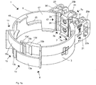
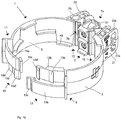
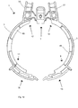
- Figures 1a-d are perspective views and top views of a pipe clip 1 for attaching a pipe (not shown) or a similar object to a support (not shown).
- Figures 1a and 1c show the pipe clip in a closed state and figures 1b and 1d show the pipe clip in an open state. In the open state the pipe clip 1 can be connected around a pipe.
- the pipe clip 1 comprises two clip segments 3, 5 which are connected to each other by means of a hingeable section 7 of the pipe clip 1.
- Each end 9, 11 of the two clip segments 3, 5 at a distance (remote) from the at least one hingeable section 7 comprises a connection section 13, 15.
- the connection sections 13, 15 are configured to be connected with each other for connecting the pipe clip 1 around a pipe or a similar object.
- the connection sections 13, 15 are connected to each other (closed state), wherein in figures 1b , 1d the connections sections 13, 15 are not connected to each other (open state).
- each opposite end 17, 19 of the two clip segments 3, 5 are connected to the hingeable section 7, wherein each opposite end 17, 19 comprises an outwardly extending flange 21, 23 comprising at least one hole 25a, 25b, i.e. in the embodiment shown in figures 1a-d each flange 21, 23 has a further hole 27a (the second hole in the flange 23 is not visible in the figures 1a-1d ).
- the holes 25a, 27a of one 21 of the two flanges are alignable by means of the hingeable section 7 with the corresponding holes 25b of the other 23 of the two flanges for receiving a fastener element (not shown in figures 1a-d ) through the two holes 25a, 25b for attaching a pipe or a similar object to a support.
- the pipe clip 1 shown in figures 1a-d has relatively compact dimensions and is easy to handle during installation such that the pipe clip 1 can be attached to a support by means of a fastener element as will be discussed below in a relatively simple, flexible and quick manner.
- each flange 21, 23 the center lines of the hole 25a and the further hole 27a extend substantially parallel. These center lines of the holes 25a, 27a further define a virtual plane extending substantially perpendicular to the flange 21, 23.
- Each flange 21, 23 extends seen from the center line of the pipe clip 1 in an outward direction from each opposite end 17, 19.
- the segments 3, 5 and the hingeable section 7 define in the closed state a pipe clip 1 having approximately the shape of a cylinder.
- the flanges 21, 23 of the pipe clip 1 further comprise additional through holes 35, 37 extending through the flange 21, 23 in a direction parallel to the center line of the pipe clip 1.
- These through holes 35, 37 are optional and may provide additional attachment options for fastener elements (not shown) to be used by an operator for attaching a pipe clip 1 to a support or object if desired.
- the hingeable section 7 comprises two hinge portions 7a, 7b connected to each other by a connecting element 7c.
- Each hinge portion 7a, 7b may have two hinge elements 22, 24, 26, 28 ( fig. 1c ) which may be constructed as a living hinge.
- the connecting element 7c comprises inwardly extending supporting flanges 29 which are vertically spaced and arranged to be positioned against a pipe to be attached to a support.
- the connecting element 7c also has an outwardly radially (seen from the center line of the pipe clip) extending portion 31 comprising a receiving member (not shown in figures 1a-d ) for receiving a fastener element passed through holes 25a, 25b.
- the pipe segments 3, 5 comprise inwardly directed supporting flanges 43, 45 arranged to be positioned against a pipe to be attached to a support. As can be seen in figures 1a , 1b the supporting flanges 43, 45 are spaced in a vertical and horizontal direction. The angle between an inner surface 47 of each of the pipe segments 3, 5 and the supporting flanges 43, 45 is 90 degrees.
- connection section 13, 15 comprises a first portion having an outer connection element 13a, 15a and a second portion having an inner connection element 13b, 15b.
- the connection sections 13, 15 have an identical configuration for connecting the first portions with the second portions, i.e. for connecting the connection sections 13, 15 hook members 13c, 15c of the outer connection elements 13a, 15a are connected/coupled over hook members 13d, 13d', 15d, 15d' of the inner connection elements 13b, 15b.
- the inner connection elements 13b, 15b have two hook members 13d, 15d ( fig. 1b ), such that the connection sections 13, 15 can be connected with each other for connecting the pipe clip 1 around pipes having varying diameters. It is also possible that in a first step the first hook members 13d', 15d' are used, and for tighter clamping/attaching the pipe clip 1 around the pipe the second hook members 13d, 15d are used in a second step.
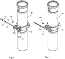
- FIGs 2 and 3a,3b show a first embodiment of the system 100.
- the pipe clip 1 of the system 100 is attached around a pipe 90.
- the system 100 further comprises a fastener element 70, wherein the fastener element 70 comprises threaded sections 71, 73 and an intermediate section 75.
- the system 100 is connected to a support (not shown) for example a wall in which a wall plug 80 can be attached in a hole in the wall.
- the first threaded sections 71 is provided to cooperate with the wall plug 80 for fixing/attaching the system 100 to the wall.
- the second threaded section 73 is a metric screw thread section ("M" series threads), in particular a M8 screw thread section.
- the flange 21 may have markings, for example M8, near the holes 25a, 27a to identify to an operator which fastener element type should preferably be used for this hole 25a, 27a.
- the fastener element 70 uses the (identical) holes 25a, 25b in the spaced apart flanges 21, 23.
- the holes 25a, 25b have tapered inner walls. This configuration of the inner walls facilitates insertion of the fastener member 70 and contributes to a strong connection between the fastener member 70 and the portion of the inner wall of the holes 25a, 25b lying against the M8 screw thread section 73 of the fastener element 70.
- the fastener element 70 is in the closed state of the pipe clip ( fig. 3b ) also connected to the receiving member 41 (which is best seen in figure 4 ) for receiving the fastener element 70.
- the receiving member 41 is provided in the portion 31 of the connecting element 7c as mentioned above.
- the fastener element is connected to the pipe clip 1 by means of the 25a, 25b and by means of the receiving section 41.
- the receiving member 41 (see figure 3a and 4 ) is also provided with an inner surface having a metric screw thread profile. It is also possible to provide the inner surface of the holes 25a, 25b at least partially with a metric screw thread profile (not shown).
- FIGs 4 and 5a , 5b show a second embodiment of the system 200.
- the difference with the system 100 is that a different type of fastener element 270 is being used to attach the pipe clip 1 connected to the pipe 90 to a support (not shown).
- the fastener element 270 is a threaded frame screw (in the Dutch language known as "kozijnschroef").
- a further difference is that instead of the holes 25a, 25b, an operator should use the holes 27a, 27b (identified in figure 2 ) to attach the pipe clip 1 to the support.
- a diameter d1 of the (identical) holes 27a, 27b through which the threaded fastener element 270 is to be positioned is smaller than the diameter d2 of the fastener element 270.
- the diameter d1 is for example 5-20% smaller than diameter d2. In this way a strong connection can be obtained between the fastener element 270 and pipe clip 1.
- the fastener element 270 can be attached to a support immediately after passing the holes 27a, 27b, such that the pipe clip 1 can be attached to the support in a relatively fast manner.
- the segments 3, 5 and/or the connecting element 7c have a smooth inner surface, i.e. an inner surface without flanges 29, 43, 45.
- the pipe 90 is allowed to move with respect to the pipe clip 1, for example as a result of thermal expansion/contraction, wherein for such applications the segments 3, 5 and/or the connecting element 7c of the pipe clip may have a smooth inner surface, i.e. an inner surface without flanges 29, 43, 45.
- connection sections 13, 15 are diametrically positioned with respect to the hingeable section 7, i.e. following the circumference of the pipe clip 1 at approximately 180 degrees, but other positions of the connection sections 13, 15 with respect to the hingeable section 7 are possible.
Landscapes
- Engineering & Computer Science (AREA)
- General Engineering & Computer Science (AREA)
- Mechanical Engineering (AREA)
- Supports For Pipes And Cables (AREA)
- Clamps And Clips (AREA)
Applications Claiming Priority (1)
| Application Number | Priority Date | Filing Date | Title |
|---|---|---|---|
| NL2022434A NL2022434B1 (en) | 2019-01-22 | 2019-01-22 | A pipe clip for attaching a pipe or a similar object to a support |
Publications (2)
| Publication Number | Publication Date |
|---|---|
| EP3686468A1 true EP3686468A1 (de) | 2020-07-29 |
| EP3686468B1 EP3686468B1 (de) | 2025-05-21 |
Family
ID=65861692
Family Applications (1)
| Application Number | Title | Priority Date | Filing Date |
|---|---|---|---|
| EP20152215.8A Active EP3686468B1 (de) | 2019-01-22 | 2020-01-16 | Rohrklemme zur befestigung eines rohres oder eines ähnlichen objekts an einem träger |
Country Status (2)
| Country | Link |
|---|---|
| EP (1) | EP3686468B1 (de) |
| NL (1) | NL2022434B1 (de) |
Cited By (1)
| Publication number | Priority date | Publication date | Assignee | Title |
|---|---|---|---|---|
| EP4745445A1 (de) * | 2024-11-19 | 2026-05-20 | Talon Manufacturing Limited | Isoliertes rohrleitungszubehör |
Citations (6)
| Publication number | Priority date | Publication date | Assignee | Title |
|---|---|---|---|---|
| US4172578A (en) * | 1978-03-16 | 1979-10-30 | Indian Head Inc. | Device for clamping conduit |
| EP0352438A1 (de) * | 1988-07-18 | 1990-01-31 | Egli, Fischer & Co. AG | Rohrschelle |
| US5462246A (en) * | 1993-10-27 | 1995-10-31 | Schlenker; Donald D. | Anti-rotation clamp for gated irrigation pipe |
| WO1997037164A1 (en) * | 1996-04-01 | 1997-10-09 | Eilif Elvegaard | A clamping device for clamping of tubes or the like |
| WO1999008032A1 (en) | 1997-08-05 | 1999-02-18 | J. Van Walraven B.V. | Pipe clip |
| US20060006292A1 (en) * | 2002-09-25 | 2006-01-12 | Pma Ag | Pipe clip |
-
2019
- 2019-01-22 NL NL2022434A patent/NL2022434B1/en active
-
2020
- 2020-01-16 EP EP20152215.8A patent/EP3686468B1/de active Active
Patent Citations (6)
| Publication number | Priority date | Publication date | Assignee | Title |
|---|---|---|---|---|
| US4172578A (en) * | 1978-03-16 | 1979-10-30 | Indian Head Inc. | Device for clamping conduit |
| EP0352438A1 (de) * | 1988-07-18 | 1990-01-31 | Egli, Fischer & Co. AG | Rohrschelle |
| US5462246A (en) * | 1993-10-27 | 1995-10-31 | Schlenker; Donald D. | Anti-rotation clamp for gated irrigation pipe |
| WO1997037164A1 (en) * | 1996-04-01 | 1997-10-09 | Eilif Elvegaard | A clamping device for clamping of tubes or the like |
| WO1999008032A1 (en) | 1997-08-05 | 1999-02-18 | J. Van Walraven B.V. | Pipe clip |
| US20060006292A1 (en) * | 2002-09-25 | 2006-01-12 | Pma Ag | Pipe clip |
Cited By (1)
| Publication number | Priority date | Publication date | Assignee | Title |
|---|---|---|---|---|
| EP4745445A1 (de) * | 2024-11-19 | 2026-05-20 | Talon Manufacturing Limited | Isoliertes rohrleitungszubehör |
Also Published As
| Publication number | Publication date |
|---|---|
| EP3686468B1 (de) | 2025-05-21 |
| NL2022434B1 (en) | 2020-08-18 |
Similar Documents
| Publication | Publication Date | Title |
|---|---|---|
| US10612720B2 (en) | Tripod assembly | |
| US20190113155A1 (en) | Multi-fit clip | |
| US10100950B2 (en) | Pipe clamp | |
| US20150316187A1 (en) | Holding device for pipe joint and pipe joint using same | |
| CN103620286B (zh) | 管夹 | |
| US11703151B2 (en) | Riser support assembly | |
| US7621486B1 (en) | Retaining device | |
| EP3686468B1 (de) | Rohrklemme zur befestigung eines rohres oder eines ähnlichen objekts an einem träger | |
| JP6702719B2 (ja) | 吊り金具用補助部材及びそれを備えた吊り金具 | |
| US8158882B1 (en) | Electrical box hanger | |
| US6554233B1 (en) | Hose clamp weight | |
| EP2682656A1 (de) | Rohrschelle mit Federscheibe | |
| EP2156083B1 (de) | Schelle für die aufhängung eines rohres | |
| KR200484299Y1 (ko) | 가두리 양식장용 발판 조립체 | |
| AU2014101243A4 (en) | Pipe clamp | |
| JP2020100961A (ja) | ボルト支持ユニット | |
| JP6109123B2 (ja) | 倒壊防止用治具 | |
| JP6928394B2 (ja) | 吊り金具用補助部材及びそれを備えた吊り金具 | |
| US6631601B1 (en) | Channel member stabilizer apparatus | |
| KR101859982B1 (ko) | 파이프 연결유닛 | |
| JP3106372U (ja) | 配管分岐装置 | |
| GB2381959A (en) | Angularly tiltable mounting assembly for supporting elongated articles | |
| KR100696448B1 (ko) | 탄성힌지형 이중벽관 분기구 | |
| US980304A (en) | Stovepipe-coupling. | |
| JPH0552476U (ja) | 筐体の内外配管接続構造 |
Legal Events
| Date | Code | Title | Description |
|---|---|---|---|
| PUAI | Public reference made under article 153(3) epc to a published international application that has entered the european phase |
Free format text: ORIGINAL CODE: 0009012 |
|
| STAA | Information on the status of an ep patent application or granted ep patent |
Free format text: STATUS: THE APPLICATION HAS BEEN PUBLISHED |
|
| AK | Designated contracting states |
Kind code of ref document: A1 Designated state(s): AL AT BE BG CH CY CZ DE DK EE ES FI FR GB GR HR HU IE IS IT LI LT LU LV MC MK MT NL NO PL PT RO RS SE SI SK SM TR |
|
| AX | Request for extension of the european patent |
Extension state: BA ME |
|
| RAP1 | Party data changed (applicant data changed or rights of an application transferred) |
Owner name: COXGEELEN B.V. |
|
| STAA | Information on the status of an ep patent application or granted ep patent |
Free format text: STATUS: REQUEST FOR EXAMINATION WAS MADE |
|
| 17P | Request for examination filed |
Effective date: 20210113 |
|
| RBV | Designated contracting states (corrected) |
Designated state(s): AL AT BE BG CH CY CZ DE DK EE ES FI FR GB GR HR HU IE IS IT LI LT LU LV MC MK MT NL NO PL PT RO RS SE SI SK SM TR |
|
| STAA | Information on the status of an ep patent application or granted ep patent |
Free format text: STATUS: EXAMINATION IS IN PROGRESS |
|
| 17Q | First examination report despatched |
Effective date: 20220503 |
|
| P01 | Opt-out of the competence of the unified patent court (upc) registered |
Effective date: 20230527 |
|
| GRAP | Despatch of communication of intention to grant a patent |
Free format text: ORIGINAL CODE: EPIDOSNIGR1 |
|
| STAA | Information on the status of an ep patent application or granted ep patent |
Free format text: STATUS: GRANT OF PATENT IS INTENDED |
|
| INTG | Intention to grant announced |
Effective date: 20250109 |
|
| GRAS | Grant fee paid |
Free format text: ORIGINAL CODE: EPIDOSNIGR3 |
|
| GRAA | (expected) grant |
Free format text: ORIGINAL CODE: 0009210 |
|
| STAA | Information on the status of an ep patent application or granted ep patent |
Free format text: STATUS: THE PATENT HAS BEEN GRANTED |
|
| AK | Designated contracting states |
Kind code of ref document: B1 Designated state(s): AL AT BE BG CH CY CZ DE DK EE ES FI FR GB GR HR HU IE IS IT LI LT LU LV MC MK MT NL NO PL PT RO RS SE SI SK SM TR |
|
| REG | Reference to a national code |
Ref country code: GB Ref legal event code: FG4D |
|
| REG | Reference to a national code |
Ref country code: CH Ref legal event code: EP |
|
| REG | Reference to a national code |
Ref country code: DE Ref legal event code: R096 Ref document number: 602020051485 Country of ref document: DE |
|
| REG | Reference to a national code |
Ref country code: IE Ref legal event code: FG4D |
|
| REG | Reference to a national code |
Ref country code: NL Ref legal event code: FP |
|
| PG25 | Lapsed in a contracting state [announced via postgrant information from national office to epo] |
Ref country code: PT Free format text: LAPSE BECAUSE OF FAILURE TO SUBMIT A TRANSLATION OF THE DESCRIPTION OR TO PAY THE FEE WITHIN THE PRESCRIBED TIME-LIMIT Effective date: 20250922 Ref country code: FI Free format text: LAPSE BECAUSE OF FAILURE TO SUBMIT A TRANSLATION OF THE DESCRIPTION OR TO PAY THE FEE WITHIN THE PRESCRIBED TIME-LIMIT Effective date: 20250521 Ref country code: ES Free format text: LAPSE BECAUSE OF FAILURE TO SUBMIT A TRANSLATION OF THE DESCRIPTION OR TO PAY THE FEE WITHIN THE PRESCRIBED TIME-LIMIT Effective date: 20250521 |
|
| REG | Reference to a national code |
Ref country code: LT Ref legal event code: MG9D |
|
| PG25 | Lapsed in a contracting state [announced via postgrant information from national office to epo] |
Ref country code: GR Free format text: LAPSE BECAUSE OF FAILURE TO SUBMIT A TRANSLATION OF THE DESCRIPTION OR TO PAY THE FEE WITHIN THE PRESCRIBED TIME-LIMIT Effective date: 20250822 Ref country code: NO Free format text: LAPSE BECAUSE OF FAILURE TO SUBMIT A TRANSLATION OF THE DESCRIPTION OR TO PAY THE FEE WITHIN THE PRESCRIBED TIME-LIMIT Effective date: 20250821 |
|
| PG25 | Lapsed in a contracting state [announced via postgrant information from national office to epo] |
Ref country code: PL Free format text: LAPSE BECAUSE OF FAILURE TO SUBMIT A TRANSLATION OF THE DESCRIPTION OR TO PAY THE FEE WITHIN THE PRESCRIBED TIME-LIMIT Effective date: 20250521 |
|
| PG25 | Lapsed in a contracting state [announced via postgrant information from national office to epo] |
Ref country code: BG Free format text: LAPSE BECAUSE OF FAILURE TO SUBMIT A TRANSLATION OF THE DESCRIPTION OR TO PAY THE FEE WITHIN THE PRESCRIBED TIME-LIMIT Effective date: 20250521 |
|
| PG25 | Lapsed in a contracting state [announced via postgrant information from national office to epo] |
Ref country code: HR Free format text: LAPSE BECAUSE OF FAILURE TO SUBMIT A TRANSLATION OF THE DESCRIPTION OR TO PAY THE FEE WITHIN THE PRESCRIBED TIME-LIMIT Effective date: 20250521 |
|
| PG25 | Lapsed in a contracting state [announced via postgrant information from national office to epo] |
Ref country code: RS Free format text: LAPSE BECAUSE OF FAILURE TO SUBMIT A TRANSLATION OF THE DESCRIPTION OR TO PAY THE FEE WITHIN THE PRESCRIBED TIME-LIMIT Effective date: 20250821 |
|
| PG25 | Lapsed in a contracting state [announced via postgrant information from national office to epo] |
Ref country code: IS Free format text: LAPSE BECAUSE OF FAILURE TO SUBMIT A TRANSLATION OF THE DESCRIPTION OR TO PAY THE FEE WITHIN THE PRESCRIBED TIME-LIMIT Effective date: 20250921 |
|
| PG25 | Lapsed in a contracting state [announced via postgrant information from national office to epo] |
Ref country code: LV Free format text: LAPSE BECAUSE OF FAILURE TO SUBMIT A TRANSLATION OF THE DESCRIPTION OR TO PAY THE FEE WITHIN THE PRESCRIBED TIME-LIMIT Effective date: 20250521 |
|
| REG | Reference to a national code |
Ref country code: AT Ref legal event code: MK05 Ref document number: 1796991 Country of ref document: AT Kind code of ref document: T Effective date: 20250521 |
|
| PG25 | Lapsed in a contracting state [announced via postgrant information from national office to epo] |
Ref country code: SM Free format text: LAPSE BECAUSE OF FAILURE TO SUBMIT A TRANSLATION OF THE DESCRIPTION OR TO PAY THE FEE WITHIN THE PRESCRIBED TIME-LIMIT Effective date: 20250521 Ref country code: AT Free format text: LAPSE BECAUSE OF FAILURE TO SUBMIT A TRANSLATION OF THE DESCRIPTION OR TO PAY THE FEE WITHIN THE PRESCRIBED TIME-LIMIT Effective date: 20250521 Ref country code: DK Free format text: LAPSE BECAUSE OF FAILURE TO SUBMIT A TRANSLATION OF THE DESCRIPTION OR TO PAY THE FEE WITHIN THE PRESCRIBED TIME-LIMIT Effective date: 20250521 |
|
| PG25 | Lapsed in a contracting state [announced via postgrant information from national office to epo] |
Ref country code: CZ Free format text: LAPSE BECAUSE OF FAILURE TO SUBMIT A TRANSLATION OF THE DESCRIPTION OR TO PAY THE FEE WITHIN THE PRESCRIBED TIME-LIMIT Effective date: 20250521 |
|
| PG25 | Lapsed in a contracting state [announced via postgrant information from national office to epo] |
Ref country code: EE Free format text: LAPSE BECAUSE OF FAILURE TO SUBMIT A TRANSLATION OF THE DESCRIPTION OR TO PAY THE FEE WITHIN THE PRESCRIBED TIME-LIMIT Effective date: 20250521 |
|
| PG25 | Lapsed in a contracting state [announced via postgrant information from national office to epo] |
Ref country code: RO Free format text: LAPSE BECAUSE OF FAILURE TO SUBMIT A TRANSLATION OF THE DESCRIPTION OR TO PAY THE FEE WITHIN THE PRESCRIBED TIME-LIMIT Effective date: 20250521 Ref country code: SK Free format text: LAPSE BECAUSE OF FAILURE TO SUBMIT A TRANSLATION OF THE DESCRIPTION OR TO PAY THE FEE WITHIN THE PRESCRIBED TIME-LIMIT Effective date: 20250521 |
|
| PG25 | Lapsed in a contracting state [announced via postgrant information from national office to epo] |
Ref country code: IT Free format text: LAPSE BECAUSE OF FAILURE TO SUBMIT A TRANSLATION OF THE DESCRIPTION OR TO PAY THE FEE WITHIN THE PRESCRIBED TIME-LIMIT Effective date: 20250521 |
|
| PGFP | Annual fee paid to national office [announced via postgrant information from national office to epo] |
Ref country code: NL Payment date: 20260121 Year of fee payment: 7 |
|
| REG | Reference to a national code |
Ref country code: DE Ref legal event code: R097 Ref document number: 602020051485 Country of ref document: DE |
|
| PLBE | No opposition filed within time limit |
Free format text: ORIGINAL CODE: 0009261 |
|
| STAA | Information on the status of an ep patent application or granted ep patent |
Free format text: STATUS: NO OPPOSITION FILED WITHIN TIME LIMIT |
|
| REG | Reference to a national code |
Ref country code: CH Ref legal event code: L10 Free format text: ST27 STATUS EVENT CODE: U-0-0-L10-L00 (AS PROVIDED BY THE NATIONAL OFFICE) Effective date: 20260402 |
|
| PGFP | Annual fee paid to national office [announced via postgrant information from national office to epo] |
Ref country code: DE Payment date: 20260121 Year of fee payment: 7 |
|
| PGFP | Annual fee paid to national office [announced via postgrant information from national office to epo] |
Ref country code: FR Payment date: 20260123 Year of fee payment: 7 |
|
| 26N | No opposition filed |
Effective date: 20260224 |
|
| PG25 | Lapsed in a contracting state [announced via postgrant information from national office to epo] |
Ref country code: LT Free format text: LAPSE BECAUSE OF FAILURE TO SUBMIT A TRANSLATION OF THE DESCRIPTION OR TO PAY THE FEE WITHIN THE PRESCRIBED TIME-LIMIT Effective date: 20250521 |
|
| PG25 | Lapsed in a contracting state [announced via postgrant information from national office to epo] |
Ref country code: SE Free format text: LAPSE BECAUSE OF FAILURE TO SUBMIT A TRANSLATION OF THE DESCRIPTION OR TO PAY THE FEE WITHIN THE PRESCRIBED TIME-LIMIT Effective date: 20250521 |