EP4238471A1 - Bodenbürstenanordnung und reinigungsausrüstung dafür - Google Patents
Bodenbürstenanordnung und reinigungsausrüstung dafür Download PDFInfo
- Publication number
- EP4238471A1 EP4238471A1 EP23159820.2A EP23159820A EP4238471A1 EP 4238471 A1 EP4238471 A1 EP 4238471A1 EP 23159820 A EP23159820 A EP 23159820A EP 4238471 A1 EP4238471 A1 EP 4238471A1
- Authority
- EP
- European Patent Office
- Prior art keywords
- scraping piece
- floor
- floor brush
- roller brush
- brush
- Prior art date
- Legal status (The legal status is an assumption and is not a legal conclusion. Google has not performed a legal analysis and makes no representation as to the accuracy of the status listed.)
- Withdrawn
Links
Images




Classifications
-
- A—HUMAN NECESSITIES
- A47—FURNITURE; DOMESTIC ARTICLES OR APPLIANCES; COFFEE MILLS; SPICE MILLS; SUCTION CLEANERS IN GENERAL
- A47L—DOMESTIC WASHING OR CLEANING; SUCTION CLEANERS IN GENERAL
- A47L11/00—Machines for cleaning floors, carpets, furniture, walls, or wall coverings
- A47L11/29—Floor-scrubbing machines characterised by means for taking-up dirty liquid
- A47L11/30—Floor-scrubbing machines characterised by means for taking-up dirty liquid by suction
- A47L11/302—Floor-scrubbing machines characterised by means for taking-up dirty liquid by suction having rotary tools
-
- A—HUMAN NECESSITIES
- A46—BRUSHWARE
- A46B—BRUSHES
- A46B13/00—Brushes with driven brush bodies or carriers
- A46B13/001—Cylindrical or annular brush bodies
-
- A—HUMAN NECESSITIES
- A46—BRUSHWARE
- A46B—BRUSHES
- A46B13/00—Brushes with driven brush bodies or carriers
- A46B13/02—Brushes with driven brush bodies or carriers power-driven carriers
-
- A—HUMAN NECESSITIES
- A46—BRUSHWARE
- A46B—BRUSHES
- A46B15/00—Other brushes; Brushes with additional arrangements
- A46B15/0055—Brushes combined with other articles normally separate from the brushing process, e.g. combs, razors, mirrors
- A46B15/0081—Brushes with a scraper, e.g. tongue scraper
-
- A—HUMAN NECESSITIES
- A47—FURNITURE; DOMESTIC ARTICLES OR APPLIANCES; COFFEE MILLS; SPICE MILLS; SUCTION CLEANERS IN GENERAL
- A47L—DOMESTIC WASHING OR CLEANING; SUCTION CLEANERS IN GENERAL
- A47L11/00—Machines for cleaning floors, carpets, furniture, walls, or wall coverings
- A47L11/40—Parts or details of machines not provided for in groups A47L11/02 - A47L11/38, or not restricted to one of these groups, e.g. handles, arrangements of switches, skirts, buffers, levers
-
- A—HUMAN NECESSITIES
- A47—FURNITURE; DOMESTIC ARTICLES OR APPLIANCES; COFFEE MILLS; SPICE MILLS; SUCTION CLEANERS IN GENERAL
- A47L—DOMESTIC WASHING OR CLEANING; SUCTION CLEANERS IN GENERAL
- A47L11/00—Machines for cleaning floors, carpets, furniture, walls, or wall coverings
- A47L11/40—Parts or details of machines not provided for in groups A47L11/02 - A47L11/38, or not restricted to one of these groups, e.g. handles, arrangements of switches, skirts, buffers, levers
- A47L11/4036—Parts or details of the surface treating tools
-
- A—HUMAN NECESSITIES
- A47—FURNITURE; DOMESTIC ARTICLES OR APPLIANCES; COFFEE MILLS; SPICE MILLS; SUCTION CLEANERS IN GENERAL
- A47L—DOMESTIC WASHING OR CLEANING; SUCTION CLEANERS IN GENERAL
- A47L11/00—Machines for cleaning floors, carpets, furniture, walls, or wall coverings
- A47L11/40—Parts or details of machines not provided for in groups A47L11/02 - A47L11/38, or not restricted to one of these groups, e.g. handles, arrangements of switches, skirts, buffers, levers
- A47L11/4036—Parts or details of the surface treating tools
- A47L11/4041—Roll shaped surface treating tools
-
- A—HUMAN NECESSITIES
- A47—FURNITURE; DOMESTIC ARTICLES OR APPLIANCES; COFFEE MILLS; SPICE MILLS; SUCTION CLEANERS IN GENERAL
- A47L—DOMESTIC WASHING OR CLEANING; SUCTION CLEANERS IN GENERAL
- A47L11/00—Machines for cleaning floors, carpets, furniture, walls, or wall coverings
- A47L11/40—Parts or details of machines not provided for in groups A47L11/02 - A47L11/38, or not restricted to one of these groups, e.g. handles, arrangements of switches, skirts, buffers, levers
- A47L11/4036—Parts or details of the surface treating tools
- A47L11/4044—Vacuuming or pick-up tools; Squeegees
-
- A—HUMAN NECESSITIES
- A47—FURNITURE; DOMESTIC ARTICLES OR APPLIANCES; COFFEE MILLS; SPICE MILLS; SUCTION CLEANERS IN GENERAL
- A47L—DOMESTIC WASHING OR CLEANING; SUCTION CLEANERS IN GENERAL
- A47L11/00—Machines for cleaning floors, carpets, furniture, walls, or wall coverings
- A47L11/40—Parts or details of machines not provided for in groups A47L11/02 - A47L11/38, or not restricted to one of these groups, e.g. handles, arrangements of switches, skirts, buffers, levers
- A47L11/408—Means for supplying cleaning or surface treating agents
-
- A—HUMAN NECESSITIES
- A47—FURNITURE; DOMESTIC ARTICLES OR APPLIANCES; COFFEE MILLS; SPICE MILLS; SUCTION CLEANERS IN GENERAL
- A47L—DOMESTIC WASHING OR CLEANING; SUCTION CLEANERS IN GENERAL
- A47L7/00—Suction cleaners adapted for additional purposes; Tables with suction openings for cleaning purposes; Containers for cleaning articles by suction; Suction cleaners adapted to cleaning of brushes; Suction cleaners adapted to taking-up liquids
- A47L7/0004—Suction cleaners adapted to take up liquids, e.g. wet or dry vacuum cleaners
- A47L7/0009—Suction cleaners adapted to take up liquids, e.g. wet or dry vacuum cleaners with means mounted on the nozzle; nozzles specially adapted for the recovery of liquid
-
- A—HUMAN NECESSITIES
- A47—FURNITURE; DOMESTIC ARTICLES OR APPLIANCES; COFFEE MILLS; SPICE MILLS; SUCTION CLEANERS IN GENERAL
- A47L—DOMESTIC WASHING OR CLEANING; SUCTION CLEANERS IN GENERAL
- A47L9/00—Details or accessories of suction cleaners, e.g. mechanical means for controlling the suction or for effecting pulsating action; Storing devices specially adapted to suction cleaners or parts thereof; Carrying-vehicles specially adapted for suction cleaners
- A47L9/02—Nozzles
- A47L9/04—Nozzles with driven brushes or agitators
Definitions
- the present invention generally relates to a floor washing machine and more particularly to a cleaning device with a brush assembly.
- the technical issue to be solved by the present invention is to provide a floor brush assembly with satisfactory cleaning performance and convenient use, and cleaning equipment with the assembly.
- a floor brush assembly for cleaning surfaces to be cleaned, with the forward direction of the floor brush assembly being the front and the opposite direction being the back.
- the floor brush assembly comprises a floor brush base, a roller brush with a roller being arranged on the floor brush base, and a second scraping piece which is arranged on the bottom of the floor brush base and in front of the roller brush and is provided with at least two second bumps distributed at intervals along its length direction. At least the roller brush abuts on the surface to be cleaned when the floor brush assembly moves forward and the interval between the adjacent second bumps forms a second channel for dirt passing through so that dirt reaches the suction inlet of the floor brush base.
- the bottom surface of the second bumps abuts on the surface to be cleaned when the floor brush assembly moves forward.
- the second scraping piece comprises the second scraping piece body arranged on the bottom of the floor brush base and the second bumps distributed at intervals on the second scraping piece body which is provided with a second mounting part on the side away from the surface to be cleaned to connect with the floor brush base and a second abutting part to abut on the surface to be cleaned, with the second abutting part and the second mounting part being distributed oppositely; wherein the second scraping piece body swings backward under external force so that the second bumps abut on the surface to be cleaned and the second scraping piece is in the fourth state at the moment when the floor brush assembly moves forward; wherein the second scraping piece body swings forward under external force so that the second abutting part abuts on the surface to be cleaned and the second scraping piece is in the third state at the moment when the floor brush assembly moves backward.
- the second scraping piece body is sheet-shaped and is provided with the third face close to the roller brush and the fourth face away from the roller brush, with the second bumps being arranged on the fourth face; wherein the second abutting part is provided with an abutting face to abut on the surface to be cleaned and the abutting face of the second abutting part can be either the third face or the face adjacent to the bottom between the third face and the fourth face.
- the second scraping piece is made from deformable materials, wherein the external force is the friction between the second scraping piece body and the surface to be cleaned; or, the second scraping piece is made from hard materials, wherein the external force is from the driver on the floor brush base, which is configured to facilitate switching of the second scraping piece between the third state and the fourth state.
- the floor brush base is provided with an extension baffle on front of the second scraping piece, wherein the bottom edge of the extension baffle is lower than the second mounting part; when the floor brush assembly moves backward, the second bumps abut on the bottom edge of the extension baffle; wherein the extension baffle is configured to exert pressure down to the second scraping piece in the third state so as to make the second scraping piece abut on the surface to be cleaned tightly.
- the second scraping piece is made from hard materials
- the second scraping piece is hinged to the bottom of the floor brush base through the second mounting part.
- the floor brush base is provided with stop blocks to limit the swing angle of the second scraping piece; wherein the stop blocks are one pair, with one of the stop blocks being arranged on the floor brush base and on the side of the second mounting part away from the roller brush to limit the swing angle when the second scraping piece swings forward and the other stop block being arranged on the floor brush base and on the side of the second mounting part close to the roller brush to limit the swing angle when the second scraping piece swings backward; or, wherein the number of the stop block is one which is provided with the second limitation face close to the roller brush and the first limitation face away from the roller brush; when the second scraping piece swings forward, the second scraping piece abutting on the first limitation face; when the second scraping piece swings backward, the second scraping piece abutting on the second limitation face.
- the floor brush assembly comprises the first scraping piece which is arranged on the bottom of the floor brush base, with a suction inlet being formed between the first scraping piece and the roller brush; wherein the first scraping piece abuts on the surface to be cleaned to scrape off dirt when the floor brush assembly moves forward and/or backward.
- the floor brush assembly comprises the first scraping piece which is arranged on the bottom of the floor brush base and behind the roller brush, with a suction inlet being formed between the first scraping piece and the roller brush and with at least two first bumps being arranged on the face away from the roller brush and distributed at intervals on the length direction of the first scraping piece; wherein the second scraping piece abuts on the surface to be cleaned and the first bump abuts on the surface to be cleaned when the floor brush assembly moves backward, with a first channel for dirt passing through being formed between the adjacent first bumps to make dirt reach the suction inlet.
- the first and auxiliary rollers are arranged on the bottom of the floor brush base and the second scraping piece and first scraping piece remain suspended in natural state; wherein the bottom edges of the second scraping piece and the first scraping piece are lower than the lowest side of the first and auxiliary rollers when the second scraping piece and the first scraping piece are in natural state.
- the floor brush base comprises the main base and the detachable roller brush cover on the main base, which form a roller brush cavity to hold the roller brush;
- the sealing element is arranged between the roller brush cover and the main base, on the top of the roller brush cover and/or the main base and on the top of the roller brush cavity for reducing or eliminating the gap between the main base and the roller brush cover so as to enhance the sealing performance of the top of the roller brush cavity.
- the first scraping piece and the second scraping piece abut on the surface to be cleaned when the floor brush assembly moves backward, with a seal structure being formed jointly by the first scraping piece, the second scraping piece and the sealing component to improve the vacuum degree of the roller brush cavity.
- the sealing component is arranged on the inner side of the roller brush cover and close to the roller brush; wherein the sealing component extends along the circumferential direction of the roller brush.
- the second scraping piece is arranged on the inner side of the roller brush cover and comprises a second mounting part which is arranged on the side of the second scraping piece body away from the surface to be cleaned; with an insertion part being arranged on the inner side of the roller brush cover to match with the second mounting part and the second scraping piece being installed on the inner side of the roller brush cover by the second mounting part matching with the abutting part.
- the present invention provides a cleaning equipment, comprising the said floor brush assemblies.
- a second channel for dirt passing through is formed between multiple second bumps provided in the present invention, through which the dirt in front of the floor brush assembly can be wiped out by the roller brush and sucked into the suction inlet, to avoid the dirt being moved forward by the floor brush assembly to form a line of dirt, which has the advantage of good cleaning effect; meanwhile, the floor brush assembly can be prevented from being lifted up repeatedly, which has the advantage of convenient use;
- the first scraping piece is designed to scrape the floor on which the water stain can be sucked into the suction inlet, thus obviously reducing water stain on the floor, which has the advantage of good cleaning performance.
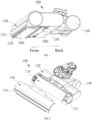
- a floor brush assembly 100 is provided for cleaning surfaces to be cleaned according to the present invention, with the forward direction of the floor brush assembly 100 being the front and the opposite direction being the back, comprising a floor brush base, a roller brush 110 and a second scraping piece 300; wherein the second scraping piece 300 is arranged on the bottom of the floor brush base and in front of the roller brush 110 with a roller being arranged on the floor brush base.
- the floor brush assembly 100 can be applied to floor scrubbers for floor cleaning. It should be noted that the application of the floor brush assembly 100 in scrubbers in the scenario is a feasible applicable scenario for the floor brush assembly 100. In other feasible and unclear scenarios, the floor brush assembly 100 can be applied to handheld vacuum cleaners.
- the floor brush base comprises the main base 120 and the detachable roller brush cover 130 on the main base 120, which form a roller brush cavity 160 to hold the roller brush 110.
- a detergent feeding unit (not shown in the Figures) for moisturizing the roller brush 110 and a fluid scraping unit with an outer circular face for squeezing the roller brush 110 to make the sewage absorbed by the roller brush 110 drop down and be sucked into the suction inlet (not shown in the Figures) are arranged on the main base 120.
- the roller brush 110 when the floor brush assembly 100 is working, the roller brush 110 will rotate in a high speed under the drive of the motor built in the floor brush assembly 100 and take the dirt on the floor below the roller brush 110 into the suction inlet; meanwhile, after being moisturized by the detergent feeding unit, the roller brush 110 will brush the floor to complete the cleaning task.
- the second scraping piece 300 extends axially along the roller brush 110 is provided with at least two second bumps 310 distributed at intervals along its length direction; wherein the number of the second bumps 310 can be two, three or more according to the size of the floor brush base.
- At least the roller brush 110 abuts on the floor when the floor brush assembly moves forward, with the second channel H2 for dirt passing through being formed between the adjacent second bumps 310 to make dirt reach the suction inlet of the floor brush base without turning up the front of or lifting up the floor brush assembly. Therefore, a line of dirt will not appear along the front of the second scraping piece 300 when the floor brush assembly 100 moves forward.
- roller brush 110 abuts on the floor when the floor brush assembly moves forward
- the roller brush 110 abuts on the floor and the second bumps 310 do not abut on the floor, or the roller brush 110 and the second bumps 310 abut on the floor.
- the bottom surface of the second bumps 310 abuts on the surface to be cleaned when the floor brush assembly moves forward.
- the roller brush 110 and the second bumps 310 abut on the floor. Therefore, when the second channel H2 formed by the second scraping piece 300 allows dirt to pass through, the dirt on the floor can be scraped off on the bottom surface of the second bumps 310, with good cleaning performance.
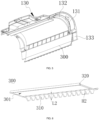
- the second scraping piece 300 comprises the second scraping piece body 301 on the bottom of the floor brush base and the second bumps 310 distributed at intervals on the second scraping piece body 301; wherein the second bumps 310 are distributed at intervals along the length direction of the second scraping piece body 301.
- Interval refers to equal interval, random interval or regular interval.
- the second scraping piece body 301 is provided with the second mounting part 320 for connecting with the floor brush base on the top (away from the floor) of the second scraping piece body 301 and the second abutting part to abut on the floor, with the second abutting part and the second mounting part 320 being distributed oppositely.
- the second scraping piece body 301 swings backward under external force so that the second bumps 310 abut on the floor and the second scraping piece 300 is in the fourth state at the moment when the floor brush assembly moves forward; the second scraping piece body 301 swings forward under external force so that the second abutting part abuts on the floor and the second scraping piece 300 is in the third state at the moment when the floor brush assembly moves backward.
- the second scraping piece 300 can switch between the third state and the fourth state.
- materials of the second scraping piece 300 have an impact on the type of the external force.
- the external force is the friction between the second scraping piece body 301 and the floor.
- the second scraping piece body 301 swings backward with the second mounting part 320 as the pivot under the impact of the friction; when the floor brush assembly moves backward, the second scraping piece body 301 swings forward with the second mounting part 320 as the pivot under the impact of the friction.
- the external force is from the driver on the floor brush base (not shown in the Figures), which is configured to facilitate switching of the second scraping piece 300 between the third state and the fourth state.
- the hard materials refer to the materials that cannot be deformed by external force.
- the deformable materials refer to the materials that can be deformed by external force.
- the second scraping piece 300 is made from deformable materials; wherein "the second scraping piece 301 is made from deformable materials” means that the second scraping piece body 301 and the second bumps 310 are made from deformable materials.
- the deformable materials can be rubber and silicone, which can be deformed under the impact of friction.
- the deformable materials are adopted for the second scraping piece body 301; to avoid the floor being scraped and damaged, the deformable materials are adopted for the second bumps 310.
- the second scraping piece body 301 and the second bumps 310 are made from the same materials for production and manufacturing convenience. Understandably, the second scraping piece body 301 and the second bumps 310 can be made from different deformable materials.
- the scraping piece 200 is made from rubber while the second bumps 310 are made from silicone.
- no limitation on the scope of protection of the embodiment of the invention is constituted.
- the second scraping piece body 301 is sheet-shaped and is provided with the third face 3011 close to the roller brush 110 and the fourth face 3012 away from the roller brush 110, with the second bumps 310 being arranged on the fourth face 3012.
- the third face 3011 and the fourth face 3012 are on the opposite side and the second bumps 310 are on the face away from the roller brush 110.
- the second abutting part is provided with an abutting face to abut on the floor and the abutting face of the second abutting part can be either the third face 3011 or the face adjacent to the bottom between the third face 3011 and the fourth face 3012; wherein the preferred abutting face of the second abutting part is the third face 3011 for the reason that when the abutting face with the second connection part is the third face 3011, the second scraping piece body 301 can touch the floor more tightly.
- the floor brush assembly 100 moves backward, the water stain and dirt on the floor can be pushed towards the roller brush 110 more effectively. In other words, when the floor brush assembly 100 moves backward, the water stain and dirt on the floor can be effectively reduced.
- the extension baffle 133 is arranged on the floor brush base.
- the extension baffle 133 is arranged on the bottom of the roller brush cover 130, which is configured to exert pressure down to the second scraping piece 300 in the third state so as to make the second scraping piece 300 abut on the floor tightly.
- the extension baffle 133 is in front of the second scraping piece 300, with the bottom edge of the extension baffle 133 lower than the second mounting part 320.
- the second bumps 310 of the second scraping piece 300 abut on the bottom edge of the extension baffle 133 under which the second scraping piece body 301 can't swing forward; meanwhile, the extension baffle 133 exerts pressure down to the second scraping piece body 301 and can make the second scraping piece body 301 tightly abut on the floor and effectively enhance the scraping force of the second scraping piece body 301 to the floor, thus scraping the water stain and dirt on the floor and improve the sealing performance of the roller brush 110 to some extents.
- the second bumps 310 are block-shaped, with the second friction face 311 on the side away from the second scraping piece body 301.
- the second friction face 311 is the bottom surface of the second bumps 310 and abuts on the floor; wherein the second friction face 311 can be either flat, cambered, polygonal or curved.
- the distance between the second friction face 311 and the second scraping piece body 301 is defined as L2 which determines the height of the second channel H2.
- the height of the second channel H2 determines the size of dirt which passes through the second channel H2, especially the height of the dirt.
- L2 should be no shorter than 3mm and no longer than 10mm, wherein L2 can be any value like 3mm, 4mm, 5mm, 6mm, 7mm, 8mm, 9mm and 10mm or any value between 3mm and 10mm with an increment of 0.1 mm, 0.2mm, 0.3mm, 0.4mm, 0.5mm, 0.6mm, 0.7mm, 0.8mm or 0.9mm.
- the second bumps 310 is provided with an adjacent face that overlaps with the fourth face 3012 and the side enclosure face 312 that connects the second friction face 311 and the adjacent face; wherein the adjacent face is the topside of the second bumps 310 when the second scraping piece 300 is in the fourth state; the side enclosure face 312 abuts on the extension baffle 133 when the second scraping piece 300 is in the third state.
- the area of the adjacent face is larger than the area of the second friction face 311. It is designed to make the second bumps 310 narrow at the bottom and wide on the top so that dirt can pass through easily when the second scraping piece 300 is in the fourth state. Additionally, if the area of the second friction face 311 is larger and the second scraping piece 300 is in the fourth state, the friction between the second friction face 311 and the floor is large, giving larger resistance against the forward movement of the floor brush assembly 100, which is not good for operation of the floor brush assembly 100.
- the adjacent face is the face that connects the second scraping piece body 301. If the area of the adjacent face is larger, the connection intensity between the second bumps 310 and the second scraping piece body 301 can be enhanced, making the connection more stable and secured.
- the second mounting part 320 is fixed to the floor brush base.
- the methods for fixing include screws, buckles, glue, or welding.
- the second scraping piece 300 is arranged on the inner side of the roller brush cover 130; wherein an insertion part is arranged on the inner side of the roller brush cover 130 to match with the second mounting part 320 and the second scraping piece 300 is installed on the inner side of the roller brush cover 130 by the second mounting part 320 matching with the abutting part; wherein the insertion part 320 and the matching part are a fixture block and a slot; wherein the second mounting part 320 is integrate with the second scraping piece body 301, which reduces the quantity of parts, streamlines processing and brings advantages in simple and compact structure.
- the second scraping piece 300 when the second scraping piece 300 is made from hard materials, the second scraping piece 300 is hinged to the floor brush base through the second mounting part 320; wherein the driver connects with the second scraping piece body 301, and the second scraping piece body 301 can rotate around the hinge axis under the drive of the driver; wherein the driver can be air cylinder or any other structure that moves repeatedly in linear.
- the second scraping piece body 301 swings backward with the hinge axis of the second scraping piece 300 as the rotational pivot under the force of the driver; when the floor brush assembly 100 moves backward, the second scraping piece body 301 swings forward with the hinge axis of the second scraping piece 300 as the rotational pivot under the force of the driver.
- the stop block 400 is arranged on the floor brush base.
- the number of the stop block 400 can be one pair or one.
- one stop block 400 is arranged on the floor brush base and on the side of the second mounting part 320 away from the roller brush 110 to limit the swing angle when the second scraping piece 300 swings forward and the other stop block is arranged on the floor brush base and on the side of the second mounting part 320 close to the roller brush 110 to limit the swing angle when the second scraping piece 300 swings backward.
- the stop block 400 is provided with the second limitation face 420 close to the roller brush 110 and the first limitation face 410 away from the roller brush 110.
- the second scraping piece 300 swings forward, the second scraping piece 300 abuts on the first limitation face 410; when the second scraping piece 300 swings backward, the second scraping piece 300 abuts on the second limitation face 420.
- the two setting solutions for the second mounting part 320 are as below.
- the second mounting part 320 is a slot, with the axis body 500 being arranged on the bottom of the floor brush assembly 100 to match with the slot of which the circumferential slot wall is provided with an opening for the axis body 500.
- the axis of the axis body 500 extends along the length direction of the second scraping piece 300 and the center line of the slot extends along the length direction of the second scraping piece 300, with coaxial distribution of the axis of the axis body 500 and the center line of the slot.
- the second mounting part 320 is a pin shaft, with a pin shaft hole being arranged on the bottom of the floor brush assembly 100 to match with the pin shaft (not shown in the Figures).
- the setting solutions of the second mounting part 320 include but not limited to the two setting solutions and include other structures that enable the second scraping piece 300 rotate on the floor brush assembly 100, and are repeated here.
- the floor brush assembly 100 includes the first scraping piece 200 that extends along the axial direction of the roller brush 110 and is arranged on the bottom of the floor brush base and behind the roller brush 110.
- the suction inlet 170 of the floor brush base is formed between the first scraping piece 200 and the roller brush 110.
- the first scraping piece 200 abuts on to scrape off the dirt.
- the working process includes forward movement, backward movement and forward and backward movement.
- the first scraping piece 200 has two structures:
- the first scraping piece 200 is sheet-shaped. When the floor brush assembly 100 moves forward or backward, the first scraping piece 200 abuts on the floor to scrape off the dirt.
- the second structure by referring to Figure 6 to Figure 11 , at least two first bumps 210 are distributed at intervals on the side of the first scraping piece 200 away from the roller brush 11 and along the length direction of the first scraping piece 200 and the interval between the adjacent first bumps 210 forms the first channel H1 for dirt passing through so that dirt reaches the suction inlet 170.
- the difference between the first structure and the second structure is the first bumps 210.
- the first structure no first bumps 210 is arranged on the first scraping piece 200; in the second structure, the first bumps 210 is arranged on the first scraping piece 200.
- the first scraping piece 200 comprises the first scraping piece body 201 on the floor brush base and the first bumps 210 on the first scraping piece body 201.
- the first scraping piece body 201 is sheet-shaped along which the first bumps 210 are distributed at intervals.
- the first scraping piece body 201 is provided with the first mounting part 230 on the top of the first scraping piece body 201 (away from the floor) to connect with the floor brush base and a first abutting part to abut on the floor, with the first abutting part and the first mounting part 230 being distributed oppositely.
- the first scraping piece body 201 swings forward under external force so that the first bumps 210 abut on the floor and the first scraping piece 200 is in the second state at the moment when the floor brush assembly 100 moves backward; the first scraping piece body 201 swings backward under external force so that the first abutting part abuts on the floor and the first scraping piece 200 is in the first state at the moment when the floor brush assembly 100 moves forward.
- the first scraping piece 200 can switch between the first state and the second state.
- materials of the first scraping piece 200 have an impact on the type of the external force.
- the external force is the friction between the first scraping piece body 201 and the floor;
- the external force is from the driver on the floor brush base (not shown in the Figures), which is configured to facilitate switching of the first scraping piece 200 between the first state and the second state.
- the first mounting part 230 is fixed to the floor brush base.
- the methods for fixing include screws, buckles, glue, or welding.
- the first mounting part 230 is hinged to the floor brush base. With the external force from the driver, the first scraping piece 200 can rotate round the hinge axle.
- the first scraping piece 200 is made from hard materials, refer to the structure of the second mounting part 320 for the structure of the first mounting part 230.
- the first scraping piece 200 is made from deformable materials.
- the first scraping piece 201 is made from deformable materials
- the deformable materials can be rubber and silicone, which can be deformed under the impact of friction. The description below is based on the situation where the first scraping piece 200 is made from deformable materials.
- the first scraping piece body 201 is provided with the first face 2011 close to the roller brush 110 and the second face 2012 away from the roller brush 110.
- the first face 2011 and the second face 2012 are on the opposite side and the first bumps 210 are on the second face 2012.
- first abutting part is provided with an abutting face to abut on the floor and the abutting face of the first abutting part can be either the first face 2011 or the face adjacent to the bottom between the first face 2011 and the second face 2012.
- the abutting face of the first abutting part is the first face 2011.
- the first scraping piece body 201 has large deformation so that the first scraping piece body 201 can touch the floor more tightly, so that the water stain and dirt on the floor can be pushed towards the suction inlet and the roller brush 110 more effectively, thus reducing the water stain and dirt on the floor to the greatest extent.
- the scraping bar 220 when the abutting face of the first abutting part is the first face 2011, the scraping bar 220 is arranged along the length direction of the first face 2011 and bulges out on the first face 2011 for the purpose of scrappaging off stubborn dirt on the floor. Setting the scraping bar 220 can enhance the structural intensity of the first scraping piece body 201 on the scraping bar 220. Therefore, compared with other areas, the area where the first scraping piece body 201 is on the scraping bar 220 will not deform easily so that the scraping bar 220 can touch the floor more tightly to scrape off the stubborn dirt on the floor.
- the outer surfaces of the scraping bar 220 comprise the third friction face 221 and the extension face 222 and are faces which don't overlap with the first face 2011.
- the extension faces 222 is on a position farther away from the bottom edge of the scraping bar 220 than the third friction face 221.
- the third friction face 221 of the scraping bar 220 abuts on the floor while the extension faces 222 is away from the floor.
- the third friction face 221 abuts on the floor for floor scraping; a space is formed with the extension face 222 gradually away from the floor to help the dirt be sucked into the suction inlet.
- the scraping bar 220 when the first scraping piece 200 is in the first state and the abutting face of the first abutting part is the first face 2011, at least the scraping bar 220 abuts on the floor. Understandably, there are two scenarios. In the first scenario, when the first scraping piece 200 is in the first state and the abutting face of the first abutting part is the first face 2011, the scraping bar 220 abuts on the floor; in the second scenario, when the first scraping piece 200 is in the first state and the abutting face of the first abutting part is the first face 2011, the scraping bar 220 and the first face 2011 abut on the floor.
- the first bump 210 has the first friction face 211 on the side away from the first scraping piece body 201.
- the first friction faces 211 abuts on the floor.
- the distance between the first friction face 211 and the first scraping piece body 201 is defined as L1 which determines the height of the first channel H1.
- the first scraping piece 200 is mainly used to scrape off the water stain on the floor.
- the first scraping piece 200 is mainly used to scrape off the water stain on the floor means that when the floor brush assembly 100 moves forward, most of the dirt are sucked into the suction inlet and only few minor dirt is left on the floor. Therefore, the first scraping piece 200 is mainly used to scrape off and reduce the water stain on the floor.
- the first scraping piece 200 can push the water stain on the floor forward. Therefore, the water stain will be either sucked into the suction inlet or absorbed by the roller brush 110, thus reducing water stain on the floor and effectively improving the cleaning performance.
- the second abutting part of the second scraping piece 300 abuts on the floor to scrape off any dirt on the floor.
- the first bump 210 abuts on the floor and the first channel H1 allows the dirt (mainly water stain) to pass through.
- the first channel H1 is mainly used for water stain passing through for the reason that when the floor brush assembly 100 moves backward, the floor has been cleaned and mainly water stain is on the floor.
- the first channel H1 is mainly used for water stain passing through, the height L1 of the first channel H1 should be lower than the height L2 of the second channel H2. In the embodiment, the height L1 of the first channel H1 should be no larger than 1 mm. In the embodiment, L1 (height of the first channel H1) can be any value like 0.5mm or 1mm, or any value between 0.1 mm and 1mm with an increment of 0.1mm, 0.2mm, 0.3mm, 0.4mm, 0.5mm, 0.6mm, 0.7mm, 0.8mm or 0.9mm.
- the second bumps 310 are distributed along the bottom edge of the second scraping piece body 301 and the first bumps 210 are distributed along the bottom edge of the first scraping piece body 201.
- the description below will take the second bumps 310 as an example.
- the first roller 140 and the auxiliary roller 150 are arranged on the bottom of the floor brush base. When the floor brush assembly 100 is pushed forward, the floor brush assembly 100 will move forward with the help of the first roller 140 and the auxiliary roller 150.
- the bottom edges of the second scraping piece 300 and first scraping piece 200 will be lower than the lowest side of the first roller 140 and the auxiliary roller 150 to ensure the first scraping piece 200 and the second scraping piece 300 can abut on the floor tightly.
- the roller brush cavity of the floor brush assembly 100, the sealing component 131 is arranged between the roller brush 130 and the main base 120.
- the sealing component 131 is above the first scraping piece 200 and the second scraping piece 300 and on the top of the roller brush cavity 160 to reduce or eliminate the gap between the main base 120 and the roller brush cover 130 and improve the sealing performance on the top of the roller brush cavity 160, thus improving the vacuum degree of the roller brush cavity 160.
- the gap refers to the gap between the roller brush cavity and the outside.
- the first scraping piece 200 and the second scraping piece 300 abut on the floor when the floor brush assembly 100 moves backward, with a seal structure being formed jointly by the first scraping piece 200, the second scraping piece 300 and the sealing component 131 to improve the vacuum degree of the roller brush cavity 160, thus improving the dirt collecting performance of the suction inlet 170 and the cleaning performance.
- the first bumps 210 are arranged on the first scraping piece 200 and the floor brush assembly 100 moves on a carpet, particularly when the floor brush assembly 100 moves backward, as the height of the first channel H1 between the first bumps 210 is small, the first channel H1 can be filled up with the fluff of the carpet, making high vacuum degree in the roller brush cavity 160.
- the vacuum degree of the roller brush cavity 160 is higher than the situation where the first bumps 210 are provided.
- the roller brush 110 is on the main base 120 and on the front side to which the floor brush assembly 100 moves forward.
- the main base 120 has two supporting ends 121.
- the two ends of the roller brush 110 are supported on the two supporting ends 121.
- One end is the active end and connects with the motor built in the floor brush assembly 100 which powers rotation of the roller brush 110.
- the other end is the passive end and supports the roller brush 110.
- the mounting positions for the sealing component 131 include the inner side of the roller brush cover 130, the main base 120 and the roller brush cover 130 and the main base 120.
- the sealing component is on the inner side of the roller brush cover 130 and distributed on the end close to the roller brush 110.
- the sealing component 131 is distributed symmetrically and extends along the circumferential direction of the roller brush 110.
- the inner side of the roller brush cover 130 is provided with a pair of bearing parts 132 with a slot through which the sealing component 131 is arranged on the bearing parts 132.
- the bearing part 132 is rib plate-shaped.
- the solutions can effectively avoid a line of dirt on the floor as the dirt can't be fully cleared by the floor brush assembly 100. At the same time, the solutions can reduce residual water stain on the floor and provide good cleaning performance.
- the present invention provides a cleaning equipment (not shown in the Figures) which includes the floor brush assembly.
Landscapes
- Engineering & Computer Science (AREA)
- Mechanical Engineering (AREA)
- Nozzles For Electric Vacuum Cleaners (AREA)
Applications Claiming Priority (1)
| Application Number | Priority Date | Filing Date | Title |
|---|---|---|---|
| CN202210208087.6A CN116725428A (zh) | 2022-03-03 | 2022-03-03 | 一种地刷组件及具有其的清洁设备 |
Publications (1)
| Publication Number | Publication Date |
|---|---|
| EP4238471A1 true EP4238471A1 (de) | 2023-09-06 |
Family
ID=85462230
Family Applications (1)
| Application Number | Title | Priority Date | Filing Date |
|---|---|---|---|
| EP23159820.2A Withdrawn EP4238471A1 (de) | 2022-03-03 | 2023-03-03 | Bodenbürstenanordnung und reinigungsausrüstung dafür |
Country Status (4)
| Country | Link |
|---|---|
| US (1) | US20230277029A1 (de) |
| EP (1) | EP4238471A1 (de) |
| CN (1) | CN116725428A (de) |
| CA (1) | CA3191596A1 (de) |
Families Citing this family (7)
| Publication number | Priority date | Publication date | Assignee | Title |
|---|---|---|---|---|
| CN117297386A (zh) * | 2023-11-15 | 2023-12-29 | 苏州市春菊电器有限公司 | 一种吸尘器地刷的浮动毛条结构 |
| USD1114445S1 (en) * | 2023-12-05 | 2026-02-17 | Suzhou Rongxuan Electric Co., Ltd | Floor brush |
| CN118044757A (zh) * | 2024-03-21 | 2024-05-17 | 广东摩飞科技有限公司 | 一种清洁装置 |
| AT528229B1 (de) * | 2024-04-22 | 2025-12-15 | Georg Hagleitner Hans | Wischeranordnung für eine, bevorzugt selbstreinigende und/oder selbstdesinfizierende, Toilette |
| WO2025260352A1 (en) * | 2024-06-21 | 2025-12-26 | Sharkninja Operating Llc | Vacuum cleaner with scraper assembly |
| CN119453851B (zh) * | 2024-12-13 | 2026-03-13 | 珠海格力电器股份有限公司 | 地刷结构及清洁装置 |
| USD1084574S1 (en) * | 2024-12-20 | 2025-07-15 | Suzhou Rongxuan Electric Co., Ltd | Floor brush |
Citations (3)
| Publication number | Priority date | Publication date | Assignee | Title |
|---|---|---|---|---|
| DE202008010134U1 (de) * | 2008-07-29 | 2009-12-31 | Vorwerk & Co. Interholding Gmbh | Düse für einen Staubsauger |
| EP2892411A1 (de) * | 2013-02-05 | 2015-07-15 | Koninklijke Philips N.V. | Düsenanordnung mit bürste und rakel |
| EP3025626A1 (de) * | 2014-11-27 | 2016-06-01 | Miele & Cie. KG | Bodendüse für ein bodenpflegegerät und verfahren zum herstellen einer bodendüse für ein bodenpflegegerät |
Family Cites Families (8)
| Publication number | Priority date | Publication date | Assignee | Title |
|---|---|---|---|---|
| US6772475B2 (en) * | 2001-02-06 | 2004-08-10 | The Hoover Company | Suction nozzle configuration |
| JP2003265372A (ja) * | 2002-03-14 | 2003-09-24 | Toshiba Tec Corp | 吸込口体と電気掃除機 |
| KR100662642B1 (ko) * | 2005-06-22 | 2007-01-02 | 삼성광주전자 주식회사 | 물청소 기능을 갖는 진공청소기 |
| CN108652519A (zh) * | 2017-03-28 | 2018-10-16 | 科沃斯机器人股份有限公司 | 地刷及其清洗吸尘机 |
| CN109381112B (zh) * | 2017-08-10 | 2024-08-06 | 添可电器有限公司 | 地刷及其清洗吸尘器 |
| CN112932357B (zh) * | 2019-12-10 | 2024-05-24 | 苏州诚河清洁设备有限公司 | 用于湿式表面清洁装置的地面吸嘴及湿式表面清洁装置 |
| CN113827147B (zh) * | 2021-10-25 | 2025-09-26 | 珠海格力电器股份有限公司 | 一种地刷和清洁装置 |
| CN217592738U (zh) * | 2022-03-03 | 2022-10-18 | 追觅创新科技(苏州)有限公司 | 一种刮擦件、地刷组件及清洁设备 |
-
2022
- 2022-03-03 CN CN202210208087.6A patent/CN116725428A/zh active Pending
-
2023
- 2023-03-02 CA CA3191596A patent/CA3191596A1/en active Pending
- 2023-03-03 EP EP23159820.2A patent/EP4238471A1/de not_active Withdrawn
- 2023-03-03 US US18/177,782 patent/US20230277029A1/en active Pending
Patent Citations (3)
| Publication number | Priority date | Publication date | Assignee | Title |
|---|---|---|---|---|
| DE202008010134U1 (de) * | 2008-07-29 | 2009-12-31 | Vorwerk & Co. Interholding Gmbh | Düse für einen Staubsauger |
| EP2892411A1 (de) * | 2013-02-05 | 2015-07-15 | Koninklijke Philips N.V. | Düsenanordnung mit bürste und rakel |
| EP3025626A1 (de) * | 2014-11-27 | 2016-06-01 | Miele & Cie. KG | Bodendüse für ein bodenpflegegerät und verfahren zum herstellen einer bodendüse für ein bodenpflegegerät |
Also Published As
| Publication number | Publication date |
|---|---|
| US20230277029A1 (en) | 2023-09-07 |
| CN116725428A (zh) | 2023-09-12 |
| CA3191596A1 (en) | 2023-09-03 |
Similar Documents
| Publication | Publication Date | Title |
|---|---|---|
| EP4238471A1 (de) | Bodenbürstenanordnung und reinigungsausrüstung dafür | |
| KR102072513B1 (ko) | 바닥 청소기 및 그 물탱크 구조 | |
| CN113455973B (zh) | 清洁设备 | |
| KR102072512B1 (ko) | 바닥 청소기 | |
| EP3686499A1 (de) | Filtersiebreinigungsmodul und luftbehandlungsvorrichtung | |
| CN111920350A (zh) | 自主清洁设备的清洁辅助模块、滚刷组件及自主清洁设备 | |
| EP4331458A1 (de) | Handgeführtes reinigungsgerät | |
| EP1808114A2 (de) | Saugdüse eines Staubsaugers | |
| CN220757341U (zh) | 洗地机 | |
| CN219166296U (zh) | 清洁设备 | |
| US5806123A (en) | Variable elasticity collection pan for floor cleaning machines | |
| KR200312080Y1 (ko) | 걸레청소기 | |
| KR20050099416A (ko) | 진공청소기용 브러쉬 | |
| CN118902330A (zh) | 一种用于清洁机的地刷组件和清洁机及其自清洁方法 | |
| CN219438992U (zh) | 清洁机器人的清扫组件和清洁机器人 | |
| AU2022427044B2 (en) | Self-cleaning dust collection seat and dust collection system | |
| CN212698730U (zh) | 一种水分离结构、具有其的自清洁除污装置及扫地机器人 | |
| CN215959648U (zh) | 洗地机滚筒装置及滚刷式蒸汽洗地机 | |
| CN208786978U (zh) | 一种安装有轴承清洗机部件的轴承清洗装置 | |
| CN222751977U (zh) | 清洁机构、清洁设备及基站 | |
| CN222955365U (zh) | 清洁设备 | |
| CN209172192U (zh) | 一种清洁组件及清洁设备 | |
| CN114869184A (zh) | 表面清洁头以及表面清洁装置 | |
| CN218684158U (zh) | 一种地刷组件 | |
| CN223944364U (zh) | 地刷组件、清洁设备以及清洁系统 |
Legal Events
| Date | Code | Title | Description |
|---|---|---|---|
| PUAI | Public reference made under article 153(3) epc to a published international application that has entered the european phase |
Free format text: ORIGINAL CODE: 0009012 |
|
| STAA | Information on the status of an ep patent application or granted ep patent |
Free format text: STATUS: THE APPLICATION HAS BEEN PUBLISHED |
|
| AK | Designated contracting states |
Kind code of ref document: A1 Designated state(s): AL AT BE BG CH CY CZ DE DK EE ES FI FR GB GR HR HU IE IS IT LI LT LU LV MC ME MK MT NL NO PL PT RO RS SE SI SK SM TR |
|
| STAA | Information on the status of an ep patent application or granted ep patent |
Free format text: STATUS: THE APPLICATION IS DEEMED TO BE WITHDRAWN |
|
| 18D | Application deemed to be withdrawn |
Effective date: 20240307 |