EP3687048B1 - Hybridrotor für eine elektrische axialflussmaschine - Google Patents
Hybridrotor für eine elektrische axialflussmaschine Download PDFInfo
- Publication number
- EP3687048B1 EP3687048B1 EP19152999.9A EP19152999A EP3687048B1 EP 3687048 B1 EP3687048 B1 EP 3687048B1 EP 19152999 A EP19152999 A EP 19152999A EP 3687048 B1 EP3687048 B1 EP 3687048B1
- Authority
- EP
- European Patent Office
- Prior art keywords
- sections
- rotor
- axial flux
- electrical machine
- flux electrical
- Prior art date
- Legal status (The legal status is an assumption and is not a legal conclusion. Google has not performed a legal analysis and makes no representation as to the accuracy of the status listed.)
- Active
Links
Images

Classifications
-
- H—ELECTRICITY
- H02—GENERATION; CONVERSION OR DISTRIBUTION OF ELECTRIC POWER
- H02K—DYNAMO-ELECTRIC MACHINES
- H02K1/00—Details of the magnetic circuit
- H02K1/02—Details of the magnetic circuit characterised by the magnetic material
-
- H—ELECTRICITY
- H02—GENERATION; CONVERSION OR DISTRIBUTION OF ELECTRIC POWER
- H02K—DYNAMO-ELECTRIC MACHINES
- H02K1/00—Details of the magnetic circuit
- H02K1/06—Details of the magnetic circuit characterised by the shape, form or construction
- H02K1/22—Rotating parts of the magnetic circuit
-
- H—ELECTRICITY
- H02—GENERATION; CONVERSION OR DISTRIBUTION OF ELECTRIC POWER
- H02K—DYNAMO-ELECTRIC MACHINES
- H02K1/00—Details of the magnetic circuit
- H02K1/06—Details of the magnetic circuit characterised by the shape, form or construction
- H02K1/22—Rotating parts of the magnetic circuit
- H02K1/24—Rotor cores with salient poles ; Variable reluctance rotors
- H02K1/246—Variable reluctance rotors
-
- H—ELECTRICITY
- H02—GENERATION; CONVERSION OR DISTRIBUTION OF ELECTRIC POWER
- H02K—DYNAMO-ELECTRIC MACHINES
- H02K1/00—Details of the magnetic circuit
- H02K1/06—Details of the magnetic circuit characterised by the shape, form or construction
- H02K1/22—Rotating parts of the magnetic circuit
- H02K1/27—Rotor cores with permanent magnets
- H02K1/2793—Rotors axially facing stators
- H02K1/2795—Rotors axially facing stators the rotor consisting of two or more circumferentially positioned magnets
- H02K1/2796—Rotors axially facing stators the rotor consisting of two or more circumferentially positioned magnets where both axial sides of the rotor face a stator
-
- H—ELECTRICITY
- H02—GENERATION; CONVERSION OR DISTRIBUTION OF ELECTRIC POWER
- H02K—DYNAMO-ELECTRIC MACHINES
- H02K1/00—Details of the magnetic circuit
- H02K1/06—Details of the magnetic circuit characterised by the shape, form or construction
- H02K1/22—Rotating parts of the magnetic circuit
- H02K1/28—Means for mounting or fastening rotating magnetic parts on to, or to, the rotor structures
-
- H—ELECTRICITY
- H02—GENERATION; CONVERSION OR DISTRIBUTION OF ELECTRIC POWER
- H02K—DYNAMO-ELECTRIC MACHINES
- H02K16/00—Machines with more than one rotor or stator
- H02K16/04—Machines with one rotor and two stators
-
- H—ELECTRICITY
- H02—GENERATION; CONVERSION OR DISTRIBUTION OF ELECTRIC POWER
- H02K—DYNAMO-ELECTRIC MACHINES
- H02K19/00—Synchronous motors or generators
- H02K19/02—Synchronous motors
- H02K19/10—Synchronous motors for multi-phase current
- H02K19/103—Motors having windings on the stator and a variable reluctance soft-iron rotor without windings
-
- H—ELECTRICITY
- H02—GENERATION; CONVERSION OR DISTRIBUTION OF ELECTRIC POWER
- H02K—DYNAMO-ELECTRIC MACHINES
- H02K21/00—Synchronous motors having permanent magnets; Synchronous generators having permanent magnets
- H02K21/12—Synchronous motors having permanent magnets; Synchronous generators having permanent magnets with stationary armatures and rotating magnets
- H02K21/24—Synchronous motors having permanent magnets; Synchronous generators having permanent magnets with stationary armatures and rotating magnets with magnets axially facing the armatures, e.g. hub-type cycle dynamos
-
- H—ELECTRICITY
- H02—GENERATION; CONVERSION OR DISTRIBUTION OF ELECTRIC POWER
- H02K—DYNAMO-ELECTRIC MACHINES
- H02K37/00—Motors with rotor rotating step by step and without interrupter or commutator driven by the rotor, e.g. stepping motors
- H02K37/02—Motors with rotor rotating step by step and without interrupter or commutator driven by the rotor, e.g. stepping motors of variable reluctance type
- H02K37/08—Motors with rotor rotating step by step and without interrupter or commutator driven by the rotor, e.g. stepping motors of variable reluctance type with rotors axially facing the stators
-
- B—PERFORMING OPERATIONS; TRANSPORTING
- B64—AIRCRAFT; AVIATION; COSMONAUTICS
- B64D—EQUIPMENT FOR FITTING IN OR TO AIRCRAFT; FLIGHT SUITS; PARACHUTES; ARRANGEMENT OR MOUNTING OF POWER PLANTS OR PROPULSION TRANSMISSIONS IN AIRCRAFT
- B64D27/00—Arrangement or mounting of power plants in aircraft; Aircraft characterised by the type or position of power plants
- B64D27/02—Aircraft characterised by the type or position of power plants
- B64D27/026—Aircraft characterised by the type or position of power plants comprising different types of power plants, e.g. combination of a piston engine and a gas-turbine
-
- B—PERFORMING OPERATIONS; TRANSPORTING
- B64—AIRCRAFT; AVIATION; COSMONAUTICS
- B64D—EQUIPMENT FOR FITTING IN OR TO AIRCRAFT; FLIGHT SUITS; PARACHUTES; ARRANGEMENT OR MOUNTING OF POWER PLANTS OR PROPULSION TRANSMISSIONS IN AIRCRAFT
- B64D27/00—Arrangement or mounting of power plants in aircraft; Aircraft characterised by the type or position of power plants
- B64D27/02—Aircraft characterised by the type or position of power plants
- B64D27/30—Aircraft characterised by electric power plants
- B64D27/33—Hybrid electric aircraft
-
- B—PERFORMING OPERATIONS; TRANSPORTING
- B64—AIRCRAFT; AVIATION; COSMONAUTICS
- B64D—EQUIPMENT FOR FITTING IN OR TO AIRCRAFT; FLIGHT SUITS; PARACHUTES; ARRANGEMENT OR MOUNTING OF POWER PLANTS OR PROPULSION TRANSMISSIONS IN AIRCRAFT
- B64D27/00—Arrangement or mounting of power plants in aircraft; Aircraft characterised by the type or position of power plants
- B64D27/02—Aircraft characterised by the type or position of power plants
- B64D27/30—Aircraft characterised by electric power plants
- B64D27/34—All-electric aircraft
-
- H—ELECTRICITY
- H02—GENERATION; CONVERSION OR DISTRIBUTION OF ELECTRIC POWER
- H02K—DYNAMO-ELECTRIC MACHINES
- H02K2213/00—Specific aspects, not otherwise provided for and not covered by codes H02K2201/00 - H02K2211/00
- H02K2213/03—Machines characterised by numerical values, ranges, mathematical expressions or similar information
Definitions
- the present invention relates to a rotor, an axial flux electrical machine, and a hybrid-electrical or electrical aircraft.
- An electrical machine transforms electrical energy into mechanical energy or vice versa, basing its principle of operation on the electromagnetic interactions of magnetic fields generated by coils, housed in a structure.
- Electrical machines are usually composed of at least one stator and at least one rotor.
- electric machines are designed and constructed to use the radial flux distribution, where rotor and stator have a small radial air gap between them.
- the winding can vary their geometric arrangement according to the required design diameter, making it possible to considerably reduce the total volume occupied by the machine.
- Axial flux electric machines have specific positioning of their magnets, which are in planes parallel to the coils, which allows to create a flux of magnetic field over a smaller rotary volume resulting in a decrease of the moment of inertia and the mass of the rotor.
- Axial flux electric machines improve efficiency, size, reliability and cost-effectiveness versus the current generation of direct drive machines (radial flux electric machines).
- the structural and electromagnetic problems related to a high-speed, reluctance-based, axial flux rotor design, particularly in the bridge regions between the poles are the high stress concentration due to centrifugal forces in the bridges between the pole segments, which limits the maximum speed. This problem can be encountered by a thicker bridge between the poles. Increasing the bridge thickness, however, also reduces the structural loads but also makes it a better flux carrier and thus reduces the difference in reluctance between the poles and the pole gaps and subsequently the power of the machine.
- Patent no. US 6803694 B2 presents a rotor made by highstrength amorphous metals but provides no solution for a high-speed application.
- WO 2010/007385 A2 , FR 3 059 169 A1 and EP 3 136 565 B1 are other examples of rotor design for axial flux electric machines.
- the object of the invention is to improve the state of the art of rotor design for axial flux reluctance-based electric machines.
- the present invention provides a rotor, an axial flux electrical machine, and a hybrid-electrical or electrical air plane.
- the invention is given by the features of the independent claims.
- a rotor comprising a first material with high magnetic permeability and a second material with low magnetic permeability which are arranged in alternating order with an interface area of both materials in between.
- the invention claims a rotor of an axial flux electrical machine, according to claim 1.
- the first material has a maximum magnetic permeability ⁇ r higher than 10 4 Hm -1 and the second material has a magnetic permeability ⁇ r under 10 1 Hm -1 .
- the first material is an amorphous metal with a high tensile strength ( ⁇ max ) over 1 GPa. This has the advantage of a high structural strength of the material.
- the second material is a structured material with a tensile strength ⁇ max over 1 GPa.
- the second material can be for example carbon fibre reinforced plastic (CFRP) or any "thin ply" composite. This has the advantage of a high structural strength of the material and low magnetic permeability.
- the tensile strength ⁇ max and tensile modulus Ey of the first material and the second material differ by less than 20%. This results in mechanical properties of the first material which are similar to/ located in the near field of the mechanical properties (e.g.: thermal extension coefficient and Young modulus) of the second material.
- the first material is arranged in the first sections in ribbon-like stripes, which form magnetic rotor poles, the second material in the second sections forms pole gaps, and the first material and the second material are arranged in interleaved laminations or layers/ plies in the third sections.
- the ribbon-like stripes of the first section can be separated by layers of non-conductive adhesive
- the second section serves to ensure the difference in reluctance resulting in a higher possible machine torque due to an increased saliency ratio and a higher possible operational speed, resulting in a higher power density of the machine.
- the rotor weight can be reduced by application of lightweight materials in the second sections, which can form pole gaps.
- the third sections serve to provide enough contact surface for a frictionally engaged connection to sustain tangential loads, which are induced by centrifugal forces at high rotational speed.
- the third section further serves as load carrying, low-permeable structure between the poles and pole gaps/ first sections and second sections, with a frictionally engaged connection to the pole material and the pole gap material/ the first material und the second material by interleave material slices.
- the torque ripple can be addressed by tailoring the magnetic properties in the interface area.
- the present invention further claims an axial flux electrical machines with a rotor according to the invention.
- This has the advantage of a more power dense electrical machines, working at speeds harder to otherwise achieve with conventional solutions. Further, the amorphous metal mass can be reduced at higher machine power, which results in lower material costs.
- the axial flux electrical machines is a reluctance-based machine.
- the present invention further claims a hybrid-electrical or electrical air plane with an axial flux electrical machine according to the invention.
- Other applications wherever a high-power density is critical, e.g. in maritime or automotive industry are possible.
- the aircraft is an air plane.
- Fig. 1 shows a rotor 4 with first sections 1, second sections 2, and third sections 3.
- the first sections 1 consists of a first material
- the second sections 2 consists of a second material
- the third sections 3 consist of the first and the second material in such a way that the first section and the second section are connected force-fitted.
- the first sections 1 and second sections 2 are arranged in alternating order and ring-shape.
- the third sections 3 form interface areas or overlapping zone between the first section 1 and second sections 2.
- the first material has a high magnetic permeability ⁇ r (in the range of 10 5 , but higher than 10 4 Hm -1 ) and the second material has a low magnetic permeability ⁇ r (in the range of 1, but under 10 1 Hm -1 ). Further, the first material is an amorphous metal with a tensile strength ( ⁇ max ) over 1 GPa. This has the advantage of a high structural strength of the material.
- the second material is a structured material with a tensile strength ⁇ max over 1 GPa.
- the second material can be for example carbon fibre reinforced plastic (CFRP) or any "thin ply" composite. This has the advantage of a high structural strength of the material and no ferro-magnetism.
- the first material is arranged in the first sections in ribbon-like stripes, which form magnetic rotor poles, the second material in the second sections form pole gaps, and the first material and the second material are arranged in interleaved laminations or layers/ plies in the third sections.
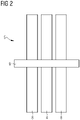
- Fig. 2 shows a reluctance-based machine 5 with a rotor 4, two stators 8 and a rotation axis 9.
- the rotor 4 is arranged between the two stators 8 and rotates around the axis 9.
- the rotor is made up according to the design of Fig. 1
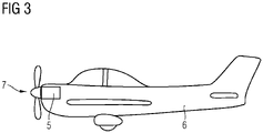
- Fig. 3 shows an air plane 6 with a reluctance-based electrical machine 5 according to Fig. 2 , as an example of an electrical machine.
- the electrical machine 5 drives a propeller 7.
- the air plane 6 is an example for an aircraft.
Landscapes
- Engineering & Computer Science (AREA)
- Power Engineering (AREA)
- Synchronous Machinery (AREA)
- Aviation & Aerospace Engineering (AREA)
- Iron Core Of Rotating Electric Machines (AREA)
Claims (9)
- Rotor (4) für eine elektrische Axialflussmaschine, umfassend:- erste Abschnitte (1) eines ersten Materials und- zweite Abschnitte (2) eines zweiten Materials, wobei die ersten Abschnitte (1) und zweiten Abschnitte (2) in abwechselnder Reihenfolge und in einer Ringform angeordnet sind, und- wobei dritte Abschnitte (3), die Grenzflächen zwischen den ersten Abschnitten (1) und zweiten Abschnitten (2) bilden, wobei die dritten Abschnitte (3) das erste Material und das zweite Material auf solche Weise umfassen, dass der erste Abschnitt (1) und der zweite Abschnitt (2) durch Kraftschluss verbunden sind,- wobei das erste Material in den ersten Abschnitten (1) in bandartigen Streifen angeordnet ist, die magnetische Rotorpole bilden,- wobei das zweite Material in den zweiten Abschnitten (2) Pollücken bildet, und- wobei das erste Material und das zweite Material in verschachtelten Laminierungen in den dritten Abschnitten (3) angeordnet sind, um eine Kontaktfläche für eine reibschlüssige Verbindung bereitzustellen, um Tangentiallasten standzuhalten, die durch Zentrifugalkräfte bei hohen Drehzahlen hervorgerufen werden.
- Rotor (4) nach Anspruch 1, wobei
das erste Material eine maximale magnetische Permeabilität (µr) von über 104 Hm-1 aufweist und das zweite Material eine magnetische Permeabilität (µr) unter 101 Hm-1 aufweist. - Rotor (4) nach einem der vorhergehenden Ansprüche, wobei das erste Material ein amorphes Metall mit einer Zugfestigkeit (σmax ) von über 1 GPa ist.
- Rotor (4) nach einem der vorhergehenden Ansprüche, wobei das zweite Material ein strukturiertes Material mit einer Zugfestigkeit (σmax ) von über 1 GPa ist.
- Rotor (4) nach einem der vorhergehenden Ansprüche, wobei sich die Zugfestigkeit (σmax ) und das Zugmodul des ersten Materials und des zweiten Materials um weniger als 20 % unterscheiden.
- Elektrische Axialflussmaschine mit einem Rotor nach einem der vorhergehenden Ansprüche.
- Elektrische Axialflussmaschine nach Anspruch 6, wobei die elektrische Axialflussmaschine eine reluktanzbasierte Maschine (5) ist.
- Hybridelektrisches oder elektrisches Luftfahrzeug (6) mit einer elektrischen Axialflussmaschine nach Anspruch 6 oder Anspruch 7.
- Luftfahrzeug nach Anspruch 8, wobei das Luftfahrzeug ein Flugzeug ist.
Priority Applications (3)
| Application Number | Priority Date | Filing Date | Title |
|---|---|---|---|
| EP19152999.9A EP3687048B1 (de) | 2019-01-22 | 2019-01-22 | Hybridrotor für eine elektrische axialflussmaschine |
| US16/747,247 US11374447B2 (en) | 2019-01-22 | 2020-01-20 | Hybrid rotor for an axial flux electrical machine |
| CN202010070880.5A CN111463914A (zh) | 2019-01-22 | 2020-01-21 | 用于轴向通量电动机器的混合转子 |
Applications Claiming Priority (1)
| Application Number | Priority Date | Filing Date | Title |
|---|---|---|---|
| EP19152999.9A EP3687048B1 (de) | 2019-01-22 | 2019-01-22 | Hybridrotor für eine elektrische axialflussmaschine |
Publications (2)
| Publication Number | Publication Date |
|---|---|
| EP3687048A1 EP3687048A1 (de) | 2020-07-29 |
| EP3687048B1 true EP3687048B1 (de) | 2022-04-06 |
Family
ID=65200608
Family Applications (1)
| Application Number | Title | Priority Date | Filing Date |
|---|---|---|---|
| EP19152999.9A Active EP3687048B1 (de) | 2019-01-22 | 2019-01-22 | Hybridrotor für eine elektrische axialflussmaschine |
Country Status (3)
| Country | Link |
|---|---|
| US (1) | US11374447B2 (de) |
| EP (1) | EP3687048B1 (de) |
| CN (1) | CN111463914A (de) |
Families Citing this family (2)
| Publication number | Priority date | Publication date | Assignee | Title |
|---|---|---|---|---|
| CN112436633B (zh) * | 2020-11-12 | 2022-03-08 | 哈尔滨工业大学 | 三段式v型串并联组合磁极可调磁通电机 |
| DE102022205899A1 (de) * | 2022-06-10 | 2023-12-21 | Rolls-Royce Deutschland Ltd & Co Kg | Elektrische Maschine mit axialem Luftspalt für ein Luftfahrzeug |
Citations (2)
| Publication number | Priority date | Publication date | Assignee | Title |
|---|---|---|---|---|
| US20090026873A1 (en) * | 2006-10-13 | 2009-01-29 | Mitsui High-Tec, Inc. | Laminated core and method for manufacturing the same |
| EP3136565B1 (de) * | 2015-08-25 | 2020-08-12 | Schmuhl Faserverbundtechnik GmbH & Co. KG | Faser-verbund-kunststoff-rotor für eine transversalfeld-erregte elektrische maschine und ein verfahren zu seiner herstellung |
Family Cites Families (6)
| Publication number | Priority date | Publication date | Assignee | Title |
|---|---|---|---|---|
| US6803694B2 (en) | 1998-11-06 | 2004-10-12 | Metglas, Inc. | Unitary amorphous metal component for an axial flux electric machine |
| GB0813032D0 (en) * | 2008-07-16 | 2008-08-20 | Cummins Generator Technologies | Axial flux machine |
| CN101741153B (zh) * | 2008-11-10 | 2013-07-31 | 株式会社日立产机系统 | 电枢铁心、使用了该电枢铁心的电动机、轴向间隙型旋转电动机、及其制造方法 |
| EP2551198B1 (de) * | 2011-07-29 | 2013-11-13 | AGUSTAWESTLAND S.p.A. | Wandelflugzeug |
| US20170338707A1 (en) * | 2014-12-22 | 2017-11-23 | Mitsubishi Electric Corporation | Rotor for rotary electrical machine |
| FR3059169B1 (fr) * | 2016-11-18 | 2022-08-26 | Renault Sas | Rotor a concentration de flux. |
-
2019
- 2019-01-22 EP EP19152999.9A patent/EP3687048B1/de active Active
-
2020
- 2020-01-20 US US16/747,247 patent/US11374447B2/en active Active
- 2020-01-21 CN CN202010070880.5A patent/CN111463914A/zh active Pending
Patent Citations (2)
| Publication number | Priority date | Publication date | Assignee | Title |
|---|---|---|---|---|
| US20090026873A1 (en) * | 2006-10-13 | 2009-01-29 | Mitsui High-Tec, Inc. | Laminated core and method for manufacturing the same |
| EP3136565B1 (de) * | 2015-08-25 | 2020-08-12 | Schmuhl Faserverbundtechnik GmbH & Co. KG | Faser-verbund-kunststoff-rotor für eine transversalfeld-erregte elektrische maschine und ein verfahren zu seiner herstellung |
Also Published As
| Publication number | Publication date |
|---|---|
| US11374447B2 (en) | 2022-06-28 |
| US20200235618A1 (en) | 2020-07-23 |
| EP3687048A1 (de) | 2020-07-29 |
| CN111463914A (zh) | 2020-07-28 |
Similar Documents
| Publication | Publication Date | Title |
|---|---|---|
| US7098569B2 (en) | Rotor assembly for a permanent magnet power electric machine | |
| US20060022541A1 (en) | Rotor hub and assembly for a permanent magnet power electric machine | |
| JP7337973B2 (ja) | 同期リラクタンス機械及び、同期リラクタンス機械を製造する方法 | |
| US7714479B2 (en) | Segmented composite rotor | |
| US20210119499A1 (en) | Electric motors for aircraft propulsion and associated systems and methods | |
| US9800125B2 (en) | Reluctance rotor with mechanical stabilizing | |
| CN103580423B (zh) | 永磁激励的同步电机的转子 | |
| JP2016013054A (ja) | 永久磁石機 | |
| CN108370206B (zh) | 用于外转动机器的转子的永磁体 | |
| JPH06311677A (ja) | ロータ組立体 | |
| US6984910B2 (en) | Generator with composite rotor coil retention components | |
| EP3410574B1 (de) | Hybridsynchronmaschine | |
| WO2007016345A1 (en) | Rotor hub and assembly for a permanent magnet power electric machine | |
| EP3082224B1 (de) | System und verfahren zur unterstützung von laminierungen von synchronen reluktanzmotoren | |
| EP3687048B1 (de) | Hybridrotor für eine elektrische axialflussmaschine | |
| US20100207478A1 (en) | Tip-located axial-gap (tag) motor/generator | |
| US10630152B2 (en) | Rotor for an asynchronous machine | |
| CN113169608B (zh) | 具有支撑结构的用于用永久磁铁励磁的电机的转子 | |
| US20220209599A1 (en) | Surface-mounted high-speed permanent magnet synchronous rotor | |
| CN112510946B (zh) | 航空航天领域用高功率密度轴横向磁通外转子永磁电机 | |
| EP4723447A1 (de) | Elektrische drehmaschine mit magnetischem getriebe | |
| CN116526718B (zh) | 一种永磁体正弦化分段的高性能高速表贴式永磁同步电机 | |
| EP4513720A1 (de) | Polstückeinheit und magnetisch angetriebene elektrische maschine | |
| WO2012042209A2 (en) | An electrical machine and a rotor for an electrical machine | |
| CN112054605A (zh) | 用于永磁电机的永磁体模块 |
Legal Events
| Date | Code | Title | Description |
|---|---|---|---|
| PUAI | Public reference made under article 153(3) epc to a published international application that has entered the european phase |
Free format text: ORIGINAL CODE: 0009012 |
|
| STAA | Information on the status of an ep patent application or granted ep patent |
Free format text: STATUS: THE APPLICATION HAS BEEN PUBLISHED |
|
| AK | Designated contracting states |
Kind code of ref document: A1 Designated state(s): AL AT BE BG CH CY CZ DE DK EE ES FI FR GB GR HR HU IE IS IT LI LT LU LV MC MK MT NL NO PL PT RO RS SE SI SK SM TR |
|
| AX | Request for extension of the european patent |
Extension state: BA ME |
|
| STAA | Information on the status of an ep patent application or granted ep patent |
Free format text: STATUS: REQUEST FOR EXAMINATION WAS MADE |
|
| 17P | Request for examination filed |
Effective date: 20210118 |
|
| RBV | Designated contracting states (corrected) |
Designated state(s): AL AT BE BG CH CY CZ DE DK EE ES FI FR GB GR HR HU IE IS IT LI LT LU LV MC MK MT NL NO PL PT RO RS SE SI SK SM TR |
|
| GRAP | Despatch of communication of intention to grant a patent |
Free format text: ORIGINAL CODE: EPIDOSNIGR1 |
|
| STAA | Information on the status of an ep patent application or granted ep patent |
Free format text: STATUS: GRANT OF PATENT IS INTENDED |
|
| INTG | Intention to grant announced |
Effective date: 20211103 |
|
| GRAS | Grant fee paid |
Free format text: ORIGINAL CODE: EPIDOSNIGR3 |
|
| GRAA | (expected) grant |
Free format text: ORIGINAL CODE: 0009210 |
|
| STAA | Information on the status of an ep patent application or granted ep patent |
Free format text: STATUS: THE PATENT HAS BEEN GRANTED |
|
| AK | Designated contracting states |
Kind code of ref document: B1 Designated state(s): AL AT BE BG CH CY CZ DE DK EE ES FI FR GB GR HR HU IE IS IT LI LT LU LV MC MK MT NL NO PL PT RO RS SE SI SK SM TR |
|
| REG | Reference to a national code |
Ref country code: GB Ref legal event code: FG4D |
|
| RIN1 | Information on inventor provided before grant (corrected) |
Inventor name: BISER, STEFAN Inventor name: RUDENKO, ANTON |
|
| REG | Reference to a national code |
Ref country code: CH Ref legal event code: EP |
|
| REG | Reference to a national code |
Ref country code: AT Ref legal event code: REF Ref document number: 1482311 Country of ref document: AT Kind code of ref document: T Effective date: 20220415 |
|
| REG | Reference to a national code |
Ref country code: DE Ref legal event code: R096 Ref document number: 602019013230 Country of ref document: DE |
|
| REG | Reference to a national code |
Ref country code: IE Ref legal event code: FG4D |
|
| REG | Reference to a national code |
Ref country code: LT Ref legal event code: MG9D |
|
| REG | Reference to a national code |
Ref country code: NL Ref legal event code: MP Effective date: 20220406 |
|
| REG | Reference to a national code |
Ref country code: AT Ref legal event code: MK05 Ref document number: 1482311 Country of ref document: AT Kind code of ref document: T Effective date: 20220406 |
|
| PG25 | Lapsed in a contracting state [announced via postgrant information from national office to epo] |
Ref country code: NL Free format text: LAPSE BECAUSE OF FAILURE TO SUBMIT A TRANSLATION OF THE DESCRIPTION OR TO PAY THE FEE WITHIN THE PRESCRIBED TIME-LIMIT Effective date: 20220406 |
|
| PG25 | Lapsed in a contracting state [announced via postgrant information from national office to epo] |
Ref country code: SE Free format text: LAPSE BECAUSE OF FAILURE TO SUBMIT A TRANSLATION OF THE DESCRIPTION OR TO PAY THE FEE WITHIN THE PRESCRIBED TIME-LIMIT Effective date: 20220406 Ref country code: PT Free format text: LAPSE BECAUSE OF FAILURE TO SUBMIT A TRANSLATION OF THE DESCRIPTION OR TO PAY THE FEE WITHIN THE PRESCRIBED TIME-LIMIT Effective date: 20220808 Ref country code: NO Free format text: LAPSE BECAUSE OF FAILURE TO SUBMIT A TRANSLATION OF THE DESCRIPTION OR TO PAY THE FEE WITHIN THE PRESCRIBED TIME-LIMIT Effective date: 20220706 Ref country code: LT Free format text: LAPSE BECAUSE OF FAILURE TO SUBMIT A TRANSLATION OF THE DESCRIPTION OR TO PAY THE FEE WITHIN THE PRESCRIBED TIME-LIMIT Effective date: 20220406 Ref country code: HR Free format text: LAPSE BECAUSE OF FAILURE TO SUBMIT A TRANSLATION OF THE DESCRIPTION OR TO PAY THE FEE WITHIN THE PRESCRIBED TIME-LIMIT Effective date: 20220406 Ref country code: GR Free format text: LAPSE BECAUSE OF FAILURE TO SUBMIT A TRANSLATION OF THE DESCRIPTION OR TO PAY THE FEE WITHIN THE PRESCRIBED TIME-LIMIT Effective date: 20220707 Ref country code: FI Free format text: LAPSE BECAUSE OF FAILURE TO SUBMIT A TRANSLATION OF THE DESCRIPTION OR TO PAY THE FEE WITHIN THE PRESCRIBED TIME-LIMIT Effective date: 20220406 Ref country code: ES Free format text: LAPSE BECAUSE OF FAILURE TO SUBMIT A TRANSLATION OF THE DESCRIPTION OR TO PAY THE FEE WITHIN THE PRESCRIBED TIME-LIMIT Effective date: 20220406 Ref country code: BG Free format text: LAPSE BECAUSE OF FAILURE TO SUBMIT A TRANSLATION OF THE DESCRIPTION OR TO PAY THE FEE WITHIN THE PRESCRIBED TIME-LIMIT Effective date: 20220706 Ref country code: AT Free format text: LAPSE BECAUSE OF FAILURE TO SUBMIT A TRANSLATION OF THE DESCRIPTION OR TO PAY THE FEE WITHIN THE PRESCRIBED TIME-LIMIT Effective date: 20220406 |
|
| PG25 | Lapsed in a contracting state [announced via postgrant information from national office to epo] |
Ref country code: RS Free format text: LAPSE BECAUSE OF FAILURE TO SUBMIT A TRANSLATION OF THE DESCRIPTION OR TO PAY THE FEE WITHIN THE PRESCRIBED TIME-LIMIT Effective date: 20220406 Ref country code: PL Free format text: LAPSE BECAUSE OF FAILURE TO SUBMIT A TRANSLATION OF THE DESCRIPTION OR TO PAY THE FEE WITHIN THE PRESCRIBED TIME-LIMIT Effective date: 20220406 Ref country code: LV Free format text: LAPSE BECAUSE OF FAILURE TO SUBMIT A TRANSLATION OF THE DESCRIPTION OR TO PAY THE FEE WITHIN THE PRESCRIBED TIME-LIMIT Effective date: 20220406 Ref country code: IS Free format text: LAPSE BECAUSE OF FAILURE TO SUBMIT A TRANSLATION OF THE DESCRIPTION OR TO PAY THE FEE WITHIN THE PRESCRIBED TIME-LIMIT Effective date: 20220806 |
|
| REG | Reference to a national code |
Ref country code: DE Ref legal event code: R097 Ref document number: 602019013230 Country of ref document: DE |
|
| PG25 | Lapsed in a contracting state [announced via postgrant information from national office to epo] |
Ref country code: SM Free format text: LAPSE BECAUSE OF FAILURE TO SUBMIT A TRANSLATION OF THE DESCRIPTION OR TO PAY THE FEE WITHIN THE PRESCRIBED TIME-LIMIT Effective date: 20220406 Ref country code: SK Free format text: LAPSE BECAUSE OF FAILURE TO SUBMIT A TRANSLATION OF THE DESCRIPTION OR TO PAY THE FEE WITHIN THE PRESCRIBED TIME-LIMIT Effective date: 20220406 Ref country code: RO Free format text: LAPSE BECAUSE OF FAILURE TO SUBMIT A TRANSLATION OF THE DESCRIPTION OR TO PAY THE FEE WITHIN THE PRESCRIBED TIME-LIMIT Effective date: 20220406 Ref country code: EE Free format text: LAPSE BECAUSE OF FAILURE TO SUBMIT A TRANSLATION OF THE DESCRIPTION OR TO PAY THE FEE WITHIN THE PRESCRIBED TIME-LIMIT Effective date: 20220406 Ref country code: DK Free format text: LAPSE BECAUSE OF FAILURE TO SUBMIT A TRANSLATION OF THE DESCRIPTION OR TO PAY THE FEE WITHIN THE PRESCRIBED TIME-LIMIT Effective date: 20220406 Ref country code: CZ Free format text: LAPSE BECAUSE OF FAILURE TO SUBMIT A TRANSLATION OF THE DESCRIPTION OR TO PAY THE FEE WITHIN THE PRESCRIBED TIME-LIMIT Effective date: 20220406 |
|
| PLBE | No opposition filed within time limit |
Free format text: ORIGINAL CODE: 0009261 |
|
| STAA | Information on the status of an ep patent application or granted ep patent |
Free format text: STATUS: NO OPPOSITION FILED WITHIN TIME LIMIT |
|
| 26N | No opposition filed |
Effective date: 20230110 |
|
| PG25 | Lapsed in a contracting state [announced via postgrant information from national office to epo] |
Ref country code: AL Free format text: LAPSE BECAUSE OF FAILURE TO SUBMIT A TRANSLATION OF THE DESCRIPTION OR TO PAY THE FEE WITHIN THE PRESCRIBED TIME-LIMIT Effective date: 20220406 |
|
| PG25 | Lapsed in a contracting state [announced via postgrant information from national office to epo] |
Ref country code: SI Free format text: LAPSE BECAUSE OF FAILURE TO SUBMIT A TRANSLATION OF THE DESCRIPTION OR TO PAY THE FEE WITHIN THE PRESCRIBED TIME-LIMIT Effective date: 20220406 |
|
| P01 | Opt-out of the competence of the unified patent court (upc) registered |
Effective date: 20230528 |
|
| REG | Reference to a national code |
Ref country code: CH Ref legal event code: PL |
|
| GBPC | Gb: european patent ceased through non-payment of renewal fee |
Effective date: 20230122 |
|
| PG25 | Lapsed in a contracting state [announced via postgrant information from national office to epo] |
Ref country code: LU Free format text: LAPSE BECAUSE OF NON-PAYMENT OF DUE FEES Effective date: 20230122 |
|
| REG | Reference to a national code |
Ref country code: BE Ref legal event code: MM Effective date: 20230131 |
|
| PG25 | Lapsed in a contracting state [announced via postgrant information from national office to epo] |
Ref country code: LI Free format text: LAPSE BECAUSE OF NON-PAYMENT OF DUE FEES Effective date: 20230131 Ref country code: GB Free format text: LAPSE BECAUSE OF NON-PAYMENT OF DUE FEES Effective date: 20230122 Ref country code: CH Free format text: LAPSE BECAUSE OF NON-PAYMENT OF DUE FEES Effective date: 20230131 |
|
| PG25 | Lapsed in a contracting state [announced via postgrant information from national office to epo] |
Ref country code: BE Free format text: LAPSE BECAUSE OF NON-PAYMENT OF DUE FEES Effective date: 20230131 |
|
| PG25 | Lapsed in a contracting state [announced via postgrant information from national office to epo] |
Ref country code: IT Free format text: LAPSE BECAUSE OF FAILURE TO SUBMIT A TRANSLATION OF THE DESCRIPTION OR TO PAY THE FEE WITHIN THE PRESCRIBED TIME-LIMIT Effective date: 20220406 Ref country code: IE Free format text: LAPSE BECAUSE OF NON-PAYMENT OF DUE FEES Effective date: 20230122 |
|
| PG25 | Lapsed in a contracting state [announced via postgrant information from national office to epo] |
Ref country code: MC Free format text: LAPSE BECAUSE OF FAILURE TO SUBMIT A TRANSLATION OF THE DESCRIPTION OR TO PAY THE FEE WITHIN THE PRESCRIBED TIME-LIMIT Effective date: 20220406 |
|
| PG25 | Lapsed in a contracting state [announced via postgrant information from national office to epo] |
Ref country code: MC Free format text: LAPSE BECAUSE OF FAILURE TO SUBMIT A TRANSLATION OF THE DESCRIPTION OR TO PAY THE FEE WITHIN THE PRESCRIBED TIME-LIMIT Effective date: 20220406 |
|
| PG25 | Lapsed in a contracting state [announced via postgrant information from national office to epo] |
Ref country code: BG Free format text: LAPSE BECAUSE OF FAILURE TO SUBMIT A TRANSLATION OF THE DESCRIPTION OR TO PAY THE FEE WITHIN THE PRESCRIBED TIME-LIMIT Effective date: 20220406 |
|
| PG25 | Lapsed in a contracting state [announced via postgrant information from national office to epo] |
Ref country code: BG Free format text: LAPSE BECAUSE OF FAILURE TO SUBMIT A TRANSLATION OF THE DESCRIPTION OR TO PAY THE FEE WITHIN THE PRESCRIBED TIME-LIMIT Effective date: 20220406 |
|
| PGFP | Annual fee paid to national office [announced via postgrant information from national office to epo] |
Ref country code: DE Payment date: 20250129 Year of fee payment: 7 |
|
| PGFP | Annual fee paid to national office [announced via postgrant information from national office to epo] |
Ref country code: FR Payment date: 20250127 Year of fee payment: 7 |
|
| PG25 | Lapsed in a contracting state [announced via postgrant information from national office to epo] |
Ref country code: CY Free format text: LAPSE BECAUSE OF FAILURE TO SUBMIT A TRANSLATION OF THE DESCRIPTION OR TO PAY THE FEE WITHIN THE PRESCRIBED TIME-LIMIT; INVALID AB INITIO Effective date: 20190122 |
|
| PG25 | Lapsed in a contracting state [announced via postgrant information from national office to epo] |
Ref country code: HU Free format text: LAPSE BECAUSE OF FAILURE TO SUBMIT A TRANSLATION OF THE DESCRIPTION OR TO PAY THE FEE WITHIN THE PRESCRIBED TIME-LIMIT; INVALID AB INITIO Effective date: 20190122 |
|
| PG25 | Lapsed in a contracting state [announced via postgrant information from national office to epo] |
Ref country code: TR Free format text: LAPSE BECAUSE OF FAILURE TO SUBMIT A TRANSLATION OF THE DESCRIPTION OR TO PAY THE FEE WITHIN THE PRESCRIBED TIME-LIMIT Effective date: 20220406 |