EP3687700B1 - Applikator mit geringem düsenabstand - Google Patents
Applikator mit geringem düsenabstand Download PDFInfo
- Publication number
- EP3687700B1 EP3687700B1 EP18778868.2A EP18778868A EP3687700B1 EP 3687700 B1 EP3687700 B1 EP 3687700B1 EP 18778868 A EP18778868 A EP 18778868A EP 3687700 B1 EP3687700 B1 EP 3687700B1
- Authority
- EP
- European Patent Office
- Prior art keywords
- actuators
- actuator
- nozzle
- valve
- nozzles
- Prior art date
- Legal status (The legal status is an assumption and is not a legal conclusion. Google has not performed a legal analysis and makes no representation as to the accuracy of the status listed.)
- Active
Links
Images







Classifications
-
- B—PERFORMING OPERATIONS; TRANSPORTING
- B05—SPRAYING OR ATOMISING IN GENERAL; APPLYING FLUENT MATERIALS TO SURFACES, IN GENERAL
- B05B—SPRAYING APPARATUS; ATOMISING APPARATUS; NOZZLES
- B05B1/00—Nozzles, spray heads or other outlets, with or without auxiliary devices such as valves, heating means
- B05B1/30—Nozzles, spray heads or other outlets, with or without auxiliary devices such as valves, heating means designed to control volume of flow, e.g. with adjustable passages
- B05B1/3033—Nozzles, spray heads or other outlets, with or without auxiliary devices such as valves, heating means designed to control volume of flow, e.g. with adjustable passages the control being effected by relative coaxial longitudinal movement of the controlling element and the spray head
- B05B1/304—Nozzles, spray heads or other outlets, with or without auxiliary devices such as valves, heating means designed to control volume of flow, e.g. with adjustable passages the control being effected by relative coaxial longitudinal movement of the controlling element and the spray head the controlling element being a lift valve
- B05B1/3046—Nozzles, spray heads or other outlets, with or without auxiliary devices such as valves, heating means designed to control volume of flow, e.g. with adjustable passages the control being effected by relative coaxial longitudinal movement of the controlling element and the spray head the controlling element being a lift valve the valve element, e.g. a needle, co-operating with a valve seat located downstream of the valve element and its actuating means, generally in the proximity of the outlet orifice
- B05B1/3053—Nozzles, spray heads or other outlets, with or without auxiliary devices such as valves, heating means designed to control volume of flow, e.g. with adjustable passages the control being effected by relative coaxial longitudinal movement of the controlling element and the spray head the controlling element being a lift valve the valve element, e.g. a needle, co-operating with a valve seat located downstream of the valve element and its actuating means, generally in the proximity of the outlet orifice the actuating means being a solenoid
-
- B—PERFORMING OPERATIONS; TRANSPORTING
- B05—SPRAYING OR ATOMISING IN GENERAL; APPLYING FLUENT MATERIALS TO SURFACES, IN GENERAL
- B05B—SPRAYING APPARATUS; ATOMISING APPARATUS; NOZZLES
- B05B1/00—Nozzles, spray heads or other outlets, with or without auxiliary devices such as valves, heating means
- B05B1/14—Nozzles, spray heads or other outlets, with or without auxiliary devices such as valves, heating means with multiple outlet openings; with strainers in or outside the outlet opening
- B05B1/16—Nozzles, spray heads or other outlets, with or without auxiliary devices such as valves, heating means with multiple outlet openings; with strainers in or outside the outlet opening having selectively- effective outlets
- B05B1/1609—Nozzles, spray heads or other outlets, with or without auxiliary devices such as valves, heating means with multiple outlet openings; with strainers in or outside the outlet opening having selectively- effective outlets with a selecting mechanism comprising a lift valve
-
- B—PERFORMING OPERATIONS; TRANSPORTING
- B41—PRINTING; LINING MACHINES; TYPEWRITERS; STAMPS
- B41J—TYPEWRITERS; SELECTIVE PRINTING MECHANISMS, i.e. MECHANISMS PRINTING OTHERWISE THAN FROM A FORME; CORRECTION OF TYPOGRAPHICAL ERRORS
- B41J2/00—Typewriters or selective printing mechanisms characterised by the printing or marking process for which they are designed
- B41J2/005—Typewriters or selective printing mechanisms characterised by the printing or marking process for which they are designed characterised by bringing liquid or particles selectively into contact with a printing material
- B41J2/01—Ink jet
- B41J2/015—Ink jet characterised by the jet generation process
- B41J2/04—Ink jet characterised by the jet generation process generating single droplets or particles on demand
-
- B—PERFORMING OPERATIONS; TRANSPORTING
- B05—SPRAYING OR ATOMISING IN GENERAL; APPLYING FLUENT MATERIALS TO SURFACES, IN GENERAL
- B05B—SPRAYING APPARATUS; ATOMISING APPARATUS; NOZZLES
- B05B1/00—Nozzles, spray heads or other outlets, with or without auxiliary devices such as valves, heating means
- B05B1/30—Nozzles, spray heads or other outlets, with or without auxiliary devices such as valves, heating means designed to control volume of flow, e.g. with adjustable passages
- B05B1/3033—Nozzles, spray heads or other outlets, with or without auxiliary devices such as valves, heating means designed to control volume of flow, e.g. with adjustable passages the control being effected by relative coaxial longitudinal movement of the controlling element and the spray head
- B05B1/304—Nozzles, spray heads or other outlets, with or without auxiliary devices such as valves, heating means designed to control volume of flow, e.g. with adjustable passages the control being effected by relative coaxial longitudinal movement of the controlling element and the spray head the controlling element being a lift valve
- B05B1/3046—Nozzles, spray heads or other outlets, with or without auxiliary devices such as valves, heating means designed to control volume of flow, e.g. with adjustable passages the control being effected by relative coaxial longitudinal movement of the controlling element and the spray head the controlling element being a lift valve the valve element, e.g. a needle, co-operating with a valve seat located downstream of the valve element and its actuating means, generally in the proximity of the outlet orifice
- B05B1/306—Nozzles, spray heads or other outlets, with or without auxiliary devices such as valves, heating means designed to control volume of flow, e.g. with adjustable passages the control being effected by relative coaxial longitudinal movement of the controlling element and the spray head the controlling element being a lift valve the valve element, e.g. a needle, co-operating with a valve seat located downstream of the valve element and its actuating means, generally in the proximity of the outlet orifice the actuating means being a fluid
-
- B—PERFORMING OPERATIONS; TRANSPORTING
- B05—SPRAYING OR ATOMISING IN GENERAL; APPLYING FLUENT MATERIALS TO SURFACES, IN GENERAL
- B05B—SPRAYING APPARATUS; ATOMISING APPARATUS; NOZZLES
- B05B13/00—Machines or plants for applying liquids or other fluent materials to surfaces of objects or other work by spraying, not covered by groups B05B1/00 - B05B11/00
- B05B13/002—Machines or plants for applying coating liquids or other fluent materials by inkjet
-
- B—PERFORMING OPERATIONS; TRANSPORTING
- B05—SPRAYING OR ATOMISING IN GENERAL; APPLYING FLUENT MATERIALS TO SURFACES, IN GENERAL
- B05B—SPRAYING APPARATUS; ATOMISING APPARATUS; NOZZLES
- B05B15/00—Details of spraying plant or spraying apparatus not otherwise provided for; Accessories
- B05B15/14—Arrangements for preventing or controlling structural damage to spraying apparatus or its outlets, e.g. for breaking at desired places; Arrangements for handling or replacing damaged parts
-
- B—PERFORMING OPERATIONS; TRANSPORTING
- B05—SPRAYING OR ATOMISING IN GENERAL; APPLYING FLUENT MATERIALS TO SURFACES, IN GENERAL
- B05B—SPRAYING APPARATUS; ATOMISING APPARATUS; NOZZLES
- B05B15/00—Details of spraying plant or spraying apparatus not otherwise provided for; Accessories
- B05B15/14—Arrangements for preventing or controlling structural damage to spraying apparatus or its outlets, e.g. for breaking at desired places; Arrangements for handling or replacing damaged parts
- B05B15/18—Arrangements for preventing or controlling structural damage to spraying apparatus or its outlets, e.g. for breaking at desired places; Arrangements for handling or replacing damaged parts for improving resistance to wear, e.g. inserts or coatings; for indicating wear; for handling or replacing worn parts
-
- B—PERFORMING OPERATIONS; TRANSPORTING
- B05—SPRAYING OR ATOMISING IN GENERAL; APPLYING FLUENT MATERIALS TO SURFACES, IN GENERAL
- B05B—SPRAYING APPARATUS; ATOMISING APPARATUS; NOZZLES
- B05B15/00—Details of spraying plant or spraying apparatus not otherwise provided for; Accessories
- B05B15/50—Arrangements for cleaning; Arrangements for preventing deposits, drying-out or blockage; Arrangements for detecting improper discharge caused by the presence of foreign matter
- B05B15/55—Arrangements for cleaning; Arrangements for preventing deposits, drying-out or blockage; Arrangements for detecting improper discharge caused by the presence of foreign matter using cleaning fluids
-
- B—PERFORMING OPERATIONS; TRANSPORTING
- B05—SPRAYING OR ATOMISING IN GENERAL; APPLYING FLUENT MATERIALS TO SURFACES, IN GENERAL
- B05B—SPRAYING APPARATUS; ATOMISING APPARATUS; NOZZLES
- B05B15/00—Details of spraying plant or spraying apparatus not otherwise provided for; Accessories
- B05B15/50—Arrangements for cleaning; Arrangements for preventing deposits, drying-out or blockage; Arrangements for detecting improper discharge caused by the presence of foreign matter
- B05B15/58—Arrangements for cleaning; Arrangements for preventing deposits, drying-out or blockage; Arrangements for detecting improper discharge caused by the presence of foreign matter preventing deposits, drying-out or blockage by recirculating the fluid to be sprayed from upstream of the discharge opening back to the supplying means
-
- B—PERFORMING OPERATIONS; TRANSPORTING
- B25—HAND TOOLS; PORTABLE POWER-DRIVEN TOOLS; MANIPULATORS
- B25J—MANIPULATORS; CHAMBERS PROVIDED WITH MANIPULATION DEVICES
- B25J11/00—Manipulators not otherwise provided for
- B25J11/0075—Manipulators for painting or coating
-
- B—PERFORMING OPERATIONS; TRANSPORTING
- B41—PRINTING; LINING MACHINES; TYPEWRITERS; STAMPS
- B41J—TYPEWRITERS; SELECTIVE PRINTING MECHANISMS, i.e. MECHANISMS PRINTING OTHERWISE THAN FROM A FORME; CORRECTION OF TYPOGRAPHICAL ERRORS
- B41J2/00—Typewriters or selective printing mechanisms characterised by the printing or marking process for which they are designed
- B41J2/005—Typewriters or selective printing mechanisms characterised by the printing or marking process for which they are designed characterised by bringing liquid or particles selectively into contact with a printing material
- B41J2/01—Ink jet
- B41J2/015—Ink jet characterised by the jet generation process
- B41J2/04—Ink jet characterised by the jet generation process generating single droplets or particles on demand
- B41J2/045—Ink jet characterised by the jet generation process generating single droplets or particles on demand by pressure, e.g. electromechanical transducers
- B41J2/04501—Control methods or devices therefor, e.g. driver circuits, control circuits
- B41J2/04581—Control methods or devices therefor, e.g. driver circuits, control circuits controlling heads based on piezoelectric elements
-
- B—PERFORMING OPERATIONS; TRANSPORTING
- B41—PRINTING; LINING MACHINES; TYPEWRITERS; STAMPS
- B41J—TYPEWRITERS; SELECTIVE PRINTING MECHANISMS, i.e. MECHANISMS PRINTING OTHERWISE THAN FROM A FORME; CORRECTION OF TYPOGRAPHICAL ERRORS
- B41J2/00—Typewriters or selective printing mechanisms characterised by the printing or marking process for which they are designed
- B41J2/005—Typewriters or selective printing mechanisms characterised by the printing or marking process for which they are designed characterised by bringing liquid or particles selectively into contact with a printing material
- B41J2/01—Ink jet
- B41J2/135—Nozzles
- B41J2/14—Structure thereof only for on-demand ink jet heads
- B41J2/14201—Structure of print heads with piezoelectric elements
-
- B—PERFORMING OPERATIONS; TRANSPORTING
- B41—PRINTING; LINING MACHINES; TYPEWRITERS; STAMPS
- B41J—TYPEWRITERS; SELECTIVE PRINTING MECHANISMS, i.e. MECHANISMS PRINTING OTHERWISE THAN FROM A FORME; CORRECTION OF TYPOGRAPHICAL ERRORS
- B41J2/00—Typewriters or selective printing mechanisms characterised by the printing or marking process for which they are designed
- B41J2/005—Typewriters or selective printing mechanisms characterised by the printing or marking process for which they are designed characterised by bringing liquid or particles selectively into contact with a printing material
- B41J2/01—Ink jet
- B41J2/135—Nozzles
- B41J2/16—Production of nozzles
-
- B—PERFORMING OPERATIONS; TRANSPORTING
- B41—PRINTING; LINING MACHINES; TYPEWRITERS; STAMPS
- B41J—TYPEWRITERS; SELECTIVE PRINTING MECHANISMS, i.e. MECHANISMS PRINTING OTHERWISE THAN FROM A FORME; CORRECTION OF TYPOGRAPHICAL ERRORS
- B41J2/00—Typewriters or selective printing mechanisms characterised by the printing or marking process for which they are designed
- B41J2/005—Typewriters or selective printing mechanisms characterised by the printing or marking process for which they are designed characterised by bringing liquid or particles selectively into contact with a printing material
- B41J2/01—Ink jet
- B41J2/135—Nozzles
- B41J2/16—Production of nozzles
- B41J2/1607—Production of print heads with piezoelectric elements
-
- B—PERFORMING OPERATIONS; TRANSPORTING
- B41—PRINTING; LINING MACHINES; TYPEWRITERS; STAMPS
- B41J—TYPEWRITERS; SELECTIVE PRINTING MECHANISMS, i.e. MECHANISMS PRINTING OTHERWISE THAN FROM A FORME; CORRECTION OF TYPOGRAPHICAL ERRORS
- B41J2/00—Typewriters or selective printing mechanisms characterised by the printing or marking process for which they are designed
- B41J2/005—Typewriters or selective printing mechanisms characterised by the printing or marking process for which they are designed characterised by bringing liquid or particles selectively into contact with a printing material
- B41J2/01—Ink jet
- B41J2/135—Nozzles
- B41J2/16—Production of nozzles
- B41J2/1621—Manufacturing processes
-
- B—PERFORMING OPERATIONS; TRANSPORTING
- B41—PRINTING; LINING MACHINES; TYPEWRITERS; STAMPS
- B41J—TYPEWRITERS; SELECTIVE PRINTING MECHANISMS, i.e. MECHANISMS PRINTING OTHERWISE THAN FROM A FORME; CORRECTION OF TYPOGRAPHICAL ERRORS
- B41J2/00—Typewriters or selective printing mechanisms characterised by the printing or marking process for which they are designed
- B41J2/005—Typewriters or selective printing mechanisms characterised by the printing or marking process for which they are designed characterised by bringing liquid or particles selectively into contact with a printing material
- B41J2/01—Ink jet
- B41J2/135—Nozzles
- B41J2/16—Production of nozzles
- B41J2/1621—Manufacturing processes
- B41J2/164—Manufacturing processes thin film formation
- B41J2/1642—Manufacturing processes thin film formation thin film formation by CVD [chemical vapor deposition]
-
- B—PERFORMING OPERATIONS; TRANSPORTING
- B41—PRINTING; LINING MACHINES; TYPEWRITERS; STAMPS
- B41J—TYPEWRITERS; SELECTIVE PRINTING MECHANISMS, i.e. MECHANISMS PRINTING OTHERWISE THAN FROM A FORME; CORRECTION OF TYPOGRAPHICAL ERRORS
- B41J2/00—Typewriters or selective printing mechanisms characterised by the printing or marking process for which they are designed
- B41J2/005—Typewriters or selective printing mechanisms characterised by the printing or marking process for which they are designed characterised by bringing liquid or particles selectively into contact with a printing material
- B41J2/01—Ink jet
- B41J2/17—Ink jet characterised by ink handling
- B41J2/175—Ink supply systems ; Circuit parts therefor
- B41J2/17596—Ink pumps, ink valves
-
- B—PERFORMING OPERATIONS; TRANSPORTING
- B41—PRINTING; LINING MACHINES; TYPEWRITERS; STAMPS
- B41M—PRINTING, DUPLICATING, MARKING, OR COPYING PROCESSES; COLOUR PRINTING
- B41M7/00—After-treatment of prints, e.g. heating, irradiating, setting of the ink, protection of the printed stock
- B41M7/0018—After-treatment of prints, e.g. heating, irradiating, setting of the ink, protection of the printed stock using ink-fixing material, e.g. mordant, precipitating agent, after printing, e.g. by ink-jet printing, coating or spraying
-
- C—CHEMISTRY; METALLURGY
- C09—DYES; PAINTS; POLISHES; NATURAL RESINS; ADHESIVES; COMPOSITIONS NOT OTHERWISE PROVIDED FOR; APPLICATIONS OF MATERIALS NOT OTHERWISE PROVIDED FOR
- C09K—MATERIALS FOR MISCELLANEOUS APPLICATIONS, NOT PROVIDED FOR ELSEWHERE
- C09K3/00—Materials not provided for elsewhere
- C09K3/10—Materials in mouldable or extrudable form for sealing or packing joints or covers
-
- B—PERFORMING OPERATIONS; TRANSPORTING
- B05—SPRAYING OR ATOMISING IN GENERAL; APPLYING FLUENT MATERIALS TO SURFACES, IN GENERAL
- B05B—SPRAYING APPARATUS; ATOMISING APPARATUS; NOZZLES
- B05B1/00—Nozzles, spray heads or other outlets, with or without auxiliary devices such as valves, heating means
- B05B1/30—Nozzles, spray heads or other outlets, with or without auxiliary devices such as valves, heating means designed to control volume of flow, e.g. with adjustable passages
- B05B1/3033—Nozzles, spray heads or other outlets, with or without auxiliary devices such as valves, heating means designed to control volume of flow, e.g. with adjustable passages the control being effected by relative coaxial longitudinal movement of the controlling element and the spray head
- B05B1/304—Nozzles, spray heads or other outlets, with or without auxiliary devices such as valves, heating means designed to control volume of flow, e.g. with adjustable passages the control being effected by relative coaxial longitudinal movement of the controlling element and the spray head the controlling element being a lift valve
- B05B1/3046—Nozzles, spray heads or other outlets, with or without auxiliary devices such as valves, heating means designed to control volume of flow, e.g. with adjustable passages the control being effected by relative coaxial longitudinal movement of the controlling element and the spray head the controlling element being a lift valve the valve element, e.g. a needle, co-operating with a valve seat located downstream of the valve element and its actuating means, generally in the proximity of the outlet orifice
-
- B—PERFORMING OPERATIONS; TRANSPORTING
- B41—PRINTING; LINING MACHINES; TYPEWRITERS; STAMPS
- B41J—TYPEWRITERS; SELECTIVE PRINTING MECHANISMS, i.e. MECHANISMS PRINTING OTHERWISE THAN FROM A FORME; CORRECTION OF TYPOGRAPHICAL ERRORS
- B41J2/00—Typewriters or selective printing mechanisms characterised by the printing or marking process for which they are designed
- B41J2/005—Typewriters or selective printing mechanisms characterised by the printing or marking process for which they are designed characterised by bringing liquid or particles selectively into contact with a printing material
- B41J2/01—Ink jet
- B41J2/015—Ink jet characterised by the jet generation process
- B41J2/04—Ink jet characterised by the jet generation process generating single droplets or particles on demand
- B41J2002/041—Electromagnetic transducer
-
- B—PERFORMING OPERATIONS; TRANSPORTING
- B41—PRINTING; LINING MACHINES; TYPEWRITERS; STAMPS
- B41J—TYPEWRITERS; SELECTIVE PRINTING MECHANISMS, i.e. MECHANISMS PRINTING OTHERWISE THAN FROM A FORME; CORRECTION OF TYPOGRAPHICAL ERRORS
- B41J2/00—Typewriters or selective printing mechanisms characterised by the printing or marking process for which they are designed
- B41J2/005—Typewriters or selective printing mechanisms characterised by the printing or marking process for which they are designed characterised by bringing liquid or particles selectively into contact with a printing material
- B41J2/01—Ink jet
- B41J2/135—Nozzles
- B41J2/14—Structure thereof only for on-demand ink jet heads
- B41J2002/14475—Structure thereof only for on-demand ink jet heads characterised by nozzle shapes or number of orifices per chamber
-
- B—PERFORMING OPERATIONS; TRANSPORTING
- B41—PRINTING; LINING MACHINES; TYPEWRITERS; STAMPS
- B41J—TYPEWRITERS; SELECTIVE PRINTING MECHANISMS, i.e. MECHANISMS PRINTING OTHERWISE THAN FROM A FORME; CORRECTION OF TYPOGRAPHICAL ERRORS
- B41J2202/00—Embodiments of or processes related to ink-jet or thermal heads
- B41J2202/01—Embodiments of or processes related to ink-jet heads
- B41J2202/05—Heads having a valve
Definitions
- the invention relates to an applicator (e.g. a print head) for applying a coating agent (e.g. paint) to a component (e.g. motor vehicle body part).
- a coating agent e.g. paint
- drop-on-demand print heads which emit a jet of droplets or a continuous jet of coating medium, the operating principle of these known drop-on-demand print heads being based on the use of electromagnetic valves.
- a magnetically driven piston is guided in a coil and moves a valve needle, which is shifted depending on the energization of the coil and either opens or closes a nozzle.
- Such printheads are also in the WO 2012/058373 A2 described. These known print heads also work with valve pistons that are moved by electrical actuators, the valve pistons running in a guide tube (coil inner tube) in the coil.
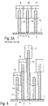
- the known drop-on-demand print heads usually have a nozzle plate 1 with numerous nozzles 2, 3, 4, droplets 5, 6, 7 being delivered onto a component 8 through the nozzles 2-4.
- the nozzles 5-7 are arranged in a linear row of nozzles in the nozzle plate 1.
- the known drop-on-demand print heads have actuators 9-11 for opening or closing the nozzles 2-4, which can be embodied, for example, as electromagnetic actuators and each move an actuator needle 12-14.
- the actuator needles 12-14 close the nozzles 2-4, so that no coating agent is discharged through the nozzles 2-4.
- the nozzles 2-4 are arranged at a specific nozzle spacing d along the row of nozzles, while the actuators 9-11 have a specific width b along the row of nozzles. This means that the nozzle spacing d between the adjacent nozzles 2-4 cannot be smaller than the width b of the actuators 9-11, since otherwise the available space along the row of nozzles for the actuators 9-11 would not be sufficient.
- the known drop-on-demand print heads are therefore rotated about an axis of rotation 15 at right angles to the surface of the component 8 and at right angles to the paint line running perpendicular to the plane of the drawing.
- the consequence of this is that the nozzle spacing d in the plane of the drawing, ie perpendicular to the paint line, is reduced.
- This twisting of the drop-on-demand print head allows the droplets 5-7 to be so close together on the surface of the component 8 that they run into a continuous film of coating agent after application, as in figure 2 is shown.
- the rotation of the drop-on-demand nozzle head thus makes it possible to solve the problem that the minimum nozzle distance d is limited at the bottom by the width b of the actuators 9-11.
- the invention is therefore based on the object of creating a correspondingly improved applicator (e.g. print head).
- an applicator e.g. print head
- an applicator e.g. print head
- the applicator according to the invention (eg print head) is generally suitable for applying a coating agent.
- the invention is thus in terms of the type of coating composition to be applied not limited to a specific coating agent.
- the print head is preferably designed for the application of a lacquer.
- the coating agent is an adhesive or a sealing material, for example for seam sealing ("sealing") in motor vehicle body components.
- the applicator according to the invention can therefore also be designed as an adhesive applicator or as a sealing material applicator.
- the applicator according to the invention e.g. print head
- the coating agent e.g. paint
- the invention is also not restricted with regard to the type of component to be coated.
- the print head according to the invention is preferably designed to apply a coating agent (e.g. paint) to a motor vehicle body part or an add-on part of a motor vehicle body part.
- the applicator according to the invention e.g. print head
- initially has a row of nozzles with a plurality of nozzles in order to apply the coating agent in the form of a jet, with the nozzles being arranged along the row of nozzles in a common nozzle plane.
- the applicator according to the invention e.g. print head
- the applicator according to the invention does not emit a spray mist of the coating agent from the nozzles, but rather spatially limited jets with only a small jet expansion.
- the print head according to the invention thus differs from atomizers (e.g. rotary atomizers, air atomizers, etc.), which do not emit a spatially limited jet of the coating agent, but rather a spray mist of the coating agent.
- the jets of coating medium emitted by the applicator can each consist of numerous droplets that are separated from one another in the longitudinal direction of the jet.
- the individual jets of coating agent can be connected in each case in the longitudinal direction of the jet and can therefore also be referred to as continuous jets of coating agent.
- the applicator e.g. print head
- the applicator can have a single row of nozzles, in which the nozzles are preferably arranged equidistantly.
- the print head has a plurality of rows of nozzles which are preferably arranged parallel to one another.
- the applicator e.g. print head
- the applicator has a plurality of actuators in order to selectively open or close the nozzles.
- the actuators can be, for example, electromagnetic actuators, piezoelectric actuators or pneumatic actuators, to name just a few examples.
- the invention is therefore not limited to a specific actuator type with regard to the physical operating principle of the actuators.
- the invention now provides that the actuators are offset at different distances at right angles to the row of nozzles in order to enable a high linear packing density of the actuators along the row of nozzles and a small distance between the nozzles of the adjacent nozzles along the row of nozzles.
- the various actuators are arranged one above the other at different vertical distances from the nozzle plane in order to enable the high linear packing density of the actuators along the nozzle row and the small nozzle spacing of the adjacent nozzles along the nozzle row.
- the arrangement of the different actuators in different planes one above the other parallel to the nozzle plane makes it possible for the actuators in the different planes to overlap with their outer contours along the row of nozzles. This is made possible by the fact that the actuators are not arranged in the same plane but in different planes at different distances from the nozzle plane. This makes it possible to reduce the nozzle spacing of the immediately adjacent nozzles below the width of the actuators along the row of nozzles.
- the actuators are arranged at different horizontal distances in the nozzle plane to the row of nozzles in order to enable the high linear packing density of the actuators along the row of nozzles and the small distance between the nozzles of the adjacent nozzles along the row of nozzles.
- the actuators are offset parallel to the plane of the nozzle at different distances to the side of the row of nozzles. This too allows the nozzle spacing between adjacent nozzles to be reduced below the width of the actuators along the row of nozzles.
- the packing density of the actuators along the row of nozzles can be increased and the distance between the nozzles can be correspondingly reduced.
- the first variant thus provides for a vertically offset arrangement of the actuators
- the second variant provides for a horizontally offset arrangement of the actuators.
- the terms “horizontal” and “vertical” each refer to the nozzle plane, i.e. with a horizontally offset arrangement of the actuators, the actuators are offset parallel to the nozzle plane, while a vertical offset means that the actuators are offset at right angles to the nozzle plane .
- the invention enables the actuators to have an outer dimension along the row of nozzles that is larger than the nozzle spacing along the row of nozzles.
- the invention thus makes it possible to reduce the distance between the nozzles without miniaturizing the actuators.
- the actuators are each connected to a displaceable valve needle.
- the nozzles of the print head are released or closed by the valve needle.
- the actuators can therefore be arranged in a linear row of actuators parallel to the row of nozzles.
- the force can be transmitted from the actuators to the valve needles by a mechanical connecting element, such as an arm (hammer), a walking beam or a rocker arm, with the rocker arm being pivotable and being able to act on one or both sides.
- the actuator needles themselves are also the valve needles, so that there is no need for a connecting element between the actuator needles and the valve needles.
- valve needles are provided in addition to the actuator needles.
- the actuator needles act on the valve needles via connecting elements (eg arm, rocker arm, hammer).
- several (e.g. two) actuators each act together on a valve needle, in particular via a common lifting beam.
- the two actuators can act on the outside of the lifting beam, while the valve needle is driven by the lifting beam in the middle of the lifting beam.
- the two actuators can selectively pull the walking beam into the closed position and push it into the open position or, conversely, push it into the closed position and pull it into the open position.
- one variant of the invention provides for the actuators to be arranged offset one above the other at different vertical distances from the nozzle plane.
- the distance between the various actuators and the nozzle plane is therefore different in this case. This allows the valve needles to be of different lengths.
- the actuators that are further away from the nozzle plane then have a longer valve needle than the actuators that are closer to the nozzle plane.
- the different length of the valve needles means that the valve needles have a different inertia behavior, so that the dynamic response behavior of the actuators is different depending on the length of the valve needles. It can therefore also be useful for all actuators to have valve needles of substantially the same length and/or weight, regardless of their distance from the nozzle plane, so that the dynamic response behavior of the actuators is uniform regardless of their distance from the nozzle plane. The various actuators then act on the valve needles of the same length at different distances from the nozzle plane.
- valve needles can be in one piece or in several pieces (e.g. two pieces).
- valve needles each have a valve needle tip that tapers conically towards its free end.
- valve needle tips each have a separate sealing element.
- the separate sealing element can be glued onto the tip of the valve needle.
- the valve needle tip has a socket into which the sealing element is inserted.
- the valve needle tip is encased by the separate sealing element over part of its length.
- valve needle and the sealing element can consist of different materials, in particular metal for the valve needle and plastic for the sealing element.
- the sealing element can be attached to the valve needle tip, for example, by an injection molding process, by dipping, by welding or by vulcanization, to name just a few examples.
- At least one of the actuator needles closes several nozzles.
- an actuator needle acts mechanically on a plurality of displaceable valve needles, each of which closes a nozzle.
- At least one of the actuator needles is connected to a sealing element that closes or opens several of the nozzles together.
- the individual nozzles are each assigned a valve seat with a separate sealing element, with the valve seat being selectively closed or opened by a valve needle tip.
- the sealing element in the valve seat and the valve needle tip can be made of metal, plastic, ceramic or semiconductor, for example, so that the nozzle needle tip on the one hand and the sealing element in the valve seat on the other hand can be a material combination of metal, ceramic, semiconductor and/or plastic.
- valve needle or the actuator needle are subjected to a restoring force by a restoring spring, with the restoring force being able to act either in the open position or in the closed position.
- the actuators act twice, i.e. in both directions. In this case, no return springs are required.
- the individual actuators can each have a position adjustment in order to adjust the position of the respective actuator within the print head.
- a position adjustment can have set screws, set rings or space reserved for shims.
- the individual actuators preferably have an actuator housing, a hammer, an armature (ram), a cover and/or a core made of a soft magnetic material, in particular with a saturation magnetization of 0.01T, 2.4T or 0. 6-2.4T.
- the actuator housing can be cylindrical, for example, and have a separate cover.
- the cover can be connected to the actuator housing by gluing or screwing, for example.
- the actuators, the actuator needles and/or the nozzle needles and the nozzle plate can be mounted in a housing.
- the housing is at least in two parts.
- the housing part in which the actuators are positioned is in two parts, so that half of the actuators and actuator rods are assigned to a first housing half and the second half of the actuators and actuator rods to a second housing half.
- the actuators can be arranged one above the other in several levels and several actuators can be arranged next to each other in each actuator level.
- valve needles of a vertical row of actuators are each positioned next to one another at a distance from the nozzle openings. Adjacent to this is a gap into which the valve needles of the vertical actuator row of the other half of the housing are positioned.
- the maximum actuator diameter d (including its delimiting walls) results from the formula i.e ⁇ H e or i.e ⁇ n right a
- the directly adjacent nozzles can have a very small nozzle spacing with respect to their nozzle center points, which can be, for example, at most 3 mm, 2 mm, 1.5 mm, 1.3 mm, 1 mm or even at most 0.8 mm.
- the directly vertically adjacent actuators can have an actuator spacing of at most 3 mm, 2 mm, 1.5 mm, 1.3 mm, 1 mm or even 0.8 mm with respect to the longitudinal axis of their valve needles.
- the nozzles can be arranged in a linear row of nozzles, in particular equidistantly.
- valve needles preferably run parallel to one another, in particular at right angles to the plane of the nozzle.
- the print head can contain a large number of nozzles, for example more than 20, 30, 40, 50, 100, 150 or even more than 200 nozzles.
- the print head can have guide elements (e.g. guide rails) for the individual actuator needles or valve needles, which stabilize the needles on their way to the nozzle plate or specify the path to the nozzle plate, in order to prevent the actuator needles or valve needles from buckling.
- the guide elements thus guide the actuator needles or valve needles radially.
- actuator needles or valve needles can have a specific ratio of diameter to length, which within the scope of the invention can be less than 0.2, 0.15, 0.007 or 0.005.
- this can preferably be in the range of 20mm-500mm, 75mm-300mm or 75mm-150mm.
- the maximum axial stroke of the individual actuator needles or valve needles is preferably in the range of 10 ⁇ m-500 ⁇ m, 30 ⁇ m-200 ⁇ m or 30 ⁇ m-100 ⁇ m.
- valve needles can be provided with an anti-corrosion coating to protect against corrosion.
- This anti-corrosion coating can consist, for example, of diamond-like carbon or carbon nitride, it being possible for the anti-corrosion coating to be applied, for example, by chemical vapor deposition (CVD) or physical vapor deposition (PVD).
- the actuators can work, for example, electromagnetically, piezoelectrically or pneumatically (single-acting or double-acting).
- the invention is therefore not limited to a specific operating principle with regard to the type of actuators.
- the actuators preferably have a coil with a number of turns of 10-2000, 200-1000 or 250-900.
- the coils are preferably wound with a coil wire that has a wire diameter of 0.05 mm-2 mm, 0.1 mm-1 mm or 0.1-0.5 mm.
- the electrical contacting of the electrically controlled actuators in the print head according to the invention can be effected, for example, by means of integrated contact pins or by leading out the coil wire.
- the actuators can be blown or flushed with a fluid, in particular with a gas such as compressed air, in order to dissipate the heat generated during operation.
- the fluid can be discharged either through the inside of the housing or through the outside of the housing.
- the external dimensions of the print head according to the invention are preferably at most 550 mm, 450 mm or 350 mm.
- the print head can have, for example, connections for the supply of coating agent, for the supply of rinsing agent, for the supply of compressed air and/or for the return line to a return. This also allows the printhead to have built-in material circulation.
- the invention not only claims protection for the print head described above as an individual component. Rather, the invention also claims protection for a coating robot (e.g. painting robot) with such a print head.
- a coating robot e.g. painting robot
- the print head can be attached to the coating robot so that it can be replaced, for example by means of a quick-change device.
- a quick-change device can have a clamping pin, for example, as is known per se from the prior art and therefore does not need to be described in more detail.
- FIG. 4 shows a schematic representation of a print head according to the invention, which is partially connected to the known print head according to FIGS Figures 3A and 3B agrees, so that to avoid repetition, reference is made to the above description, the same reference numerals being used for corresponding details.
- a special feature of this exemplary embodiment is that the actuators 9-11 are not arranged in the same plane parallel to the plane of the nozzle plate 1. Rather, the actuators 9-11 are arranged at different distances from the plane of the nozzle plate 1 in such a way that their outer contours do not overlap in the vertical direction (i.e. at right angles to the plane of the nozzle plate 1). This makes it possible to reduce the distance between the actuators 9-11 along the row of nozzles without requiring additional miniaturization of the actuators 9-11. The nozzle spacing d can therefore be less than the width b of the individual actuators 9-11.
- the actuators 9-11 are arranged in three different actuator planes parallel to the plane of the nozzle plate 1.
- the various actuators 9 , 10 are only arranged in two different actuator planes parallel to the plane of the nozzle plate 1 .
- figure 6 shows a schematic representation of a further possible exemplary embodiment of the invention, which again partially corresponds to the exemplary embodiments described above, so that reference is made to the above description to avoid repetition.
- a special feature here is that the actuators 9-11 are offset both vertically and horizontally.
- the valve function is fulfilled by the valve needles 16-18, which are driven by the actuators 9-11 via mechanical connecting elements 19-21 (e.g. arm, walking beam, rocker arm).
- figure 7 shows a modification of the embodiment according to FIG figure 4 , so that, in order to avoid repetition, reference is made to the above description, the same reference numbers being used for corresponding details.
- valve needles 12-14 have a uniform length and therefore also have a uniform mass. This is advantageous because the dynamic response behavior of the actuators 9-10 is not changed by different inertial masses.
- figure 8 shows a sectional view of an actuator 22 according to the invention with an armature 23 that can be displaced in the direction of the double arrow, a housing 24, a coil 25, a coil former 26 and a magnetic core 27.
- the movable armature 23 transmits its movement to a valve needle 29 via a hammer 28.
- figure 9 shows a schematic representation of a valve needle 30 with a valve needle tip 31 with an additional seal.
- a sealing membrane 32 is shown here, which separates a nozzle chamber 33 filled with coating agent from an actuator chamber 34 .
- the sealing membrane 32 prevents the coating agent from passing from the nozzle chamber 33 into the actuator chamber 34 and contaminating the actuators there.
- figure 10 shows an embodiment of the invention, in which an actuator 35 acts with its actuator needle 36 on five valve needles 37 and thus selectively closes or opens a plurality of nozzles 38 in a nozzle plate 39 .
- FIG figure 11 shows a modification of the embodiment according to FIG figure 10 .
- the actuator needle 36 acts on a sealing element 40 which then selectively releases or closes several of the nozzles 38 .
- figure 12 shows a modification of figure 8 , so that, in order to avoid repetition, reference is made to the above description, the same reference numbers being used for corresponding details.
- a special feature of this representation is that an adjustment device 41 is also shown in order to be able to adjust the position of the actuator 22 in the print head.
- figure 12 also an integrated contacting 43 for electrical contacting of the coil 25.
- figure 13 shows a modification of figure 12 , so that to avoid repetition, reference is made to the above description and the same reference numbers are used for the corresponding details.
- a special feature of this exemplary embodiment is that instead of the integrated electrical contact 43, a hole 44 is provided for electrical contact. The cable ends of the coil can be fed out of this hole.
- FIG 14 shows a schematic representation to clarify a second variant of the invention.
- nozzles 45 are arranged equidistantly along the nozzle row 46 at a specific nozzle spacing d.
- the nozzles 45 are released or closed by valve needles (not shown), with the individual valve needles being driven mechanically by actuators 47 .
- the actuators 47 are offset at different distances laterally next to the row of nozzles 46 with respect to the row of nozzles 46 . This allows the linear packing density of the actuators 47 is increased along the row of nozzles 46, so that the nozzle spacing d can also be reduced accordingly.
- figure 15 shows a schematic representation of the mechanical activation of a valve needle 48, which is passed through a sealing membrane 49 and with its valve needle tip 50 a nozzle 51 in a nozzle plate 52 either opens or closes.
- the valve needle 48 is controlled by two actuators 53, 54, which act on the nozzle needle 48 via a common lifting beam 55.
- the two actuators 53, 54 act on the outside of the lifting beam 55, while the lifting beam 55 acts on the nozzle needle 48 at its center.
- figure 16 shows a modification of figure 15 , so that, in order to avoid repetition, reference is made to the above description, the same reference numbers being used for corresponding details.
- a special feature of this exemplary embodiment is that the two actuators 53, 54 press the valve needle 48 into the closed position and pull it into the open position.
- figure 17 shows a modification of figures 15 and 16, so that to avoid repetition, reference is again made to the above description, with the same reference numbers being used for corresponding details.
- valve needle 48 is driven by a single actuator 56 via a one-sided rocker arm 57, with the rocker arm 57 being pivotably mounted in a support 58.
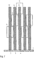
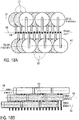
- FIGS. 18A and 18B show a modification of the embodiment according to FIG figure 6 , so that to avoid repetition, reference is also made to the above description.
- nozzles 59 are arranged equidistantly one behind the other in a nozzle row 60 .
- An actuator row 61, 62 is arranged on both sides of the nozzle row 60, specifically parallel to the nozzle row 60.
- the row of actuators 62 here comprises a plurality of actuators 63 which are arranged one above the other in three actuator planes 64, 65, 66, as shown in FIG Figure 18B is evident.
- the other row of actuators 61 also includes a plurality of actuators 67, which are also arranged one above the other in the three actuator levels 64-66.
- the actuators are arranged so that they are spatially equalized both horizontally (i.e. transversely to the row of nozzles 60) and vertically (i.e. perpendicularly to the plane of the nozzles). This enables the nozzle spacing between the adjacent nozzles 59 of the nozzle row 60 to be reduced.
- valve needles for the nozzles 59 of the nozzle row 60 are alternately connected to the actuators 67, 63 of the two actuator rows 61, 62.
- FIGS Figures 19A and 19B show a modification of the embodiment according to FIGS Figures 18A and 18B , so that, in order to avoid repetition, reference is made to the above description, the same reference numbers being used for corresponding details.
- a special feature of this exemplary embodiment is that the actuators 63, 67 are always connected in groups to the associated valve needles for the nozzles 59.
- the valve needles for the first three nozzles 59 of the row of nozzles 60 are controlled by the first three actuators 67 of the row of actuators 61 .
- the valve needles for the next three nozzles 59 in the nozzle row 60 are then controlled by the first three actuators 63 in the other actuator row 62 .
- figure 20 shows a schematic representation to explain the spatial rectification of actuators, both in the vertical direction (ie perpendicular to the nozzle plane) and in the horizontal direction (ie parallel to the nozzle plane).
- two rows of actuators are arranged parallel to one another and parallel to the row of nozzles in three actuator planes shown as examples one above the other.
- the right-hand actuator row includes two actuators a.1.1 and a.1.2, while the other actuator row has two actuators b.1.1 and b.1.2, for example.
- middle actuator level which also has two rows of actuators, each with two actuators a.2.1, a.2.2 or b.2.1 or b.2.2.
- the lower actuator level also contains two rows of actuators, each with two actuators a.3.1, a.3.2 or b.3.1, b.3.2, for example.
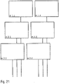
- figure 21 shows a modification of figure 20 , so that, in order to avoid repetition, reference is made to the above description, the same reference numbers being used for corresponding details.
- a special feature of this exemplary embodiment is that the actuators a.1.1, a.1.2, a.2.1, a.2.2, a.3.1, a.3.2 are spatially equalized only vertically, i.e. in three actuator levels one above the other. However, horizontal spatial equalization (i.e. across the row of nozzles) is not intended.
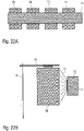
- FIGS. 22A and 22B show a schematic illustration for explaining the cooling of actuators 68-71 by compressed air 72, which flows out of a compressed air distributor 73 through a nozzle 74 and is directed onto the actuators 68-71 in order to cool the actuators 68-71.
- the individual actuators 68-71 each act on a valve needle 76 via a hammer 75.
- FIGS. 23-25 show various possible configurations for the passage, connection or placement of valve needles 77 through a sealing membrane 78.
- valve needle 77 is continuous and thus forms with its nozzle closing tip 79 at the same time a sealing element for closing or releasing a corresponding valve seat.
- a sealing collar 80 is formed onto the sealing membrane 14 and protrudes from the sealing membrane 78 both towards an actuator chamber 81 and towards a nozzle chamber 82 .
- the nozzle sealing tip 79 is separated from the valve needle 77 and screwed to the valve needle 77.
- the sealing membrane 78 is pressed between the valve needle 77 and the nozzle closure tip 79, so that the valve needle 77 is firmly connected to the sealing membrane 78.
- a displacement of the valve needle 77 thus leads to a corresponding deflection of the sealing membrane 78.
- the sealing membrane 78 has no hole for the valve needle 77 to pass through. Rather, the nozzle closure tip 79 is formed integrally with the sealing membrane 78 .
- the valve needle 77 is firmly connected to the sealing membrane 78, so that a displacement of the valve needle 77 leads to a corresponding deflection of the sealing membrane 78.
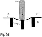
- FIG 26 shows a sealing membrane 78 with molded nozzle sealing tips 79.
- the valve needle 77 can be connected to the sealing membrane 78, but it can also just be attached. If the valve needle 77 is only attached, the nozzle is opened by the paint pressure. The paint pressure deforms the sealing membrane 78 away from the nozzle chamber 82 in the direction of the actuator chamber 81 .
Landscapes
- Engineering & Computer Science (AREA)
- Manufacturing & Machinery (AREA)
- Chemical & Material Sciences (AREA)
- Robotics (AREA)
- Mechanical Engineering (AREA)
- Materials Engineering (AREA)
- Organic Chemistry (AREA)
- Coating Apparatus (AREA)
- Nozzles (AREA)
- Closures For Containers (AREA)
Description
- Die Erfindung betrifft einen Applikator (z.B. einen Druckkopf) zur Applikation eines Beschichtungsmittels (z.B. Lack) auf ein Bauteil (z.B. Kraftfahrzeugkarosseriebauteil).
- Aus dem Stand der Technik (z.B.
US 9 108 424 B2 - Derartige Druckköpfe werden auch in der
WO 2012/058373 A2 beschrieben. Diese bekannten Druckköpfe arbeiten ebenfalls mit Ventilkolben, die durch elektrische Aktoren bewegt werden, wobei die Ventilkolben in einem Führungsrohr (Spuleninnenrohr) in der Spule verlaufen. - Problematisch bei den bekannten Drop-on-Demand-Druckköpfen ist der Düsenabstand zwischen den benachbarten Düsen, wie nachfolgend unter Bezugnahme auf die
Figuren 1, 2 ,3A und3B beschrieben wird. So weisen die bekannten Drop-on-Demand-Druckköpfe üblicherweise eine Düsenplatte 1 mit zahlreichen Düsen 2, 3, 4 auf, wobei durch die Düsen 2-4 Tröpfchen 5, 6, 7 auf ein Bauteil 8 abgegeben werden. Die Düsen 5-7 sind hierbei in einer linearen Düsenreihe in der Düsenplatte 1 angeordnet. Darüber hinaus weisen die bekannten Drop-on-Demand-Druckköpfe zum Öffnen bzw. Verschließen der Düsen 2-4 Aktoren 9-11 auf, die beispielsweise als elektromagnetische Aktoren ausgebildet sein können und jeweils eine Aktornadel 12-14 verschieben. In der inFigur 3A gezeigten Stellung der Aktornadeln 12-14 verschließen die Aktornadeln 12-14 die Düsen 2-4, so dass kein Beschichtungsmittel durch die Düsen 2-4 abgegeben wird. Die Düsen 2-4 sind hierbei in einem bestimmten Düsenabstand d entlang der Düsenreihe angeordnet, während die Aktoren 9-11 eine bestimmte Breite b entlang der Düsenreihe aufweisen. Dies bedeutet, dass der Düsenabstand d zwischen den benachbarten Düsen 2-4 nicht kleiner werden kann als die Breite b der Aktoren 9-11, da sonst der zur Verfügung stehende Bauraum entlang der Düsenreihe für die Aktoren 9-11 nicht ausreichen würde. - Bei der Darstellung gemäß
Figur 1 sind die Tröpfchen 5-7 auf dem Bauteil 8 deshalb so weit voneinander entfernt, dass die Tröpfchen 5-7 nicht zu einem durchgehenden Beschichtungsmittelfilm auf dem Bauteil 8 führen, was inakzeptabel ist. - Im Betrieb werden die bekannten Drop-on-Demand-Druckköpfe deshalb um eine Drehachse 15 rechtwinklig zur Oberfläche des Bauteils 8 und rechtwinklig zu der senkrecht zur Zeichenebene verlaufenden Lackierbahn gedreht. Dies hat zur Folge, dass der Düsenabstand d in der Zeichenebene, d.h. rechtwinklig zur Lackierbahn verringert wird. Diese Verdrehung des Drop-on-Demand-Druckkopfs ermöglicht es, dass die Tröpfchen 5-7 auf der Oberfläche des Bauteils 8 so nah zusammenliegen, dass sie nach dem Auftragen zu einem durchgehenden Beschichtungsmittelfilm verlaufen, wie in
Figur 2 dargestellt ist. Die Drehung des Drop-on-Demand-Düsenkopfs ermöglicht also eine Lösung des Problems, dass der minimale Düsenabstand d durch die Breite b der Aktoren 9-11 nach unten begrenzt ist. Allerdings wäre es wünschenswert, auf eine solche Drehung verzichten zu können. Insbesondere wäre es wünschenswert, den Düsenabstand in einem Druckkopf zu verringern. - Zum allgemeinen technischen Hintergrund der Erfindung ist auch hinzuweisen auf
DE 33 02 617 A1 ,US 2013/0127955 A1 ,EP 0 426 473 A2 ,US 2005/0046673 A1 ,EP 1 862 311 A1 ,US 2015/0360472 A1 ,US 4 157 149 A ,WO 2012/072576 A1 ,US 2 296 079 A ,DE 35 06 393 A1 ,US 5 800 614 A ,EP 0 276 053 A1 ,WO 2007/056098 A2 undWO 2010/046064 A1 . - Schließlich offenbart
DE 36 34 137 A1 einen Druckkopf gemäß dem Oberbegriff von Anspruch 1. Dieser bekannte Druckkopf ist jedoch noch nicht vollständig befriedigend. - Der Erfindung liegt deshalb die Aufgabe zugrunde, einen entsprechend verbesserten Applikator (z.B. Druckkopf) zu schaffen.
- Diese Aufgabe wird durch einen erfindungsgemäßen Applikator (z.B. Druckkopf) gemäß dem Hauptanspruch gelöst.
- Der erfindungsgemäße Applikator (z.B. Druckkopf) eignet sich allgemein zur Applikation eines Beschichtungsmittels. Die Erfindung ist also hinsichtlich des Typs des zu applizierenden Beschichtungsmittels nicht auf ein bestimmtes Beschichtungsmittel beschränkt. Vorzugsweise ist der Druckkopf jedoch zur Applikation eines Lacks ausgelegt. Alternativ besteht jedoch im Rahmen der Erfindung auch die Möglichkeit, dass es sich bei dem Beschichtungsmittel um einen Klebstoff oder um ein Dichtungsmaterial handelt, beispielsweise zur Nahtabdichtung ("Sealing") bei Kraftfahrzeugkarosseriebauteilen. Der erfindungsgemäße Applikator kann also auch als Klebstoff-Applikator oder als Dichtungsmaterial-Applikator ausgebildet sein.
- Weiterhin ist zu erwähnen, dass der erfindungsgemäße Applikator (z.B. Druckkopf) allgemein geeignet ist, um das Beschichtungsmittel (z.B. Lack) auf ein bestimmtes Bauteil zu applizieren. Hinsichtlich des Typs des zu beschichtenden Bauteils ist die Erfindung ebenfalls nicht beschränkt. Vorzugsweise ist der erfindungsgemäße Druckkopf jedoch dazu ausgelegt, ein Beschichtungsmittel (z.B. Lack) auf ein Kraftfahrzeugkarosseriebauteil oder ein Anbauteil eines Kraftfahrzeugkarosseriebauteils zu applizieren.
- Der erfindungsgemäße Applikator (z.B. Druckkopf) weist zunächst in Übereinstimmung mit dem Stand der Technik eine Düsenreihe mit mehreren Düsen auf, um das Beschichtungsmittel jeweils in Form eines Strahls zu applizieren, wobei die Düsen entlang der Düsenreihe in einer gemeinsamen Düsenebene angeordnet sind.
- Hierbei ist zu erwähnen, dass der erfindungsgemäße Applikator (z.B. Druckkopf) aus den Düsen keinen Sprühnebel des Beschichtungsmittels abgibt, sondern jeweils räumlich begrenzte Strahlen mit einer nur geringeren Strahlaufweitung. Der erfindungsgemäße Druckkopf unterscheidet sich also von Zerstäubern (z.B. Rotationszerstäuber, Luftzerstäuber, etc.), die keinen räumlich begrenzten Strahl des Beschichtungsmittels abgeben, sondern einen Sprühnebel des Beschichtungsmittels.
- Hierbei ist auch zu erwähnen, dass die von dem Applikator abgegebenen Beschichtungsmittelstrahlen jeweils aus zahlreichen Tröpfchen bestehen können, die in Strahllängsrichtung voneinander getrennt sind. Es ist jedoch alternativ auch möglich, dass die einzelnen Beschichtungsmittelstrahlen jeweils in Strahllängsrichtung zusammenhängen und deshalb auch als kontinuierliche Beschichtungsmittelstrahlen bezeichnet werden können.
- Weiterhin ist zu erwähnen, dass der erfindungsgemäße Applikator (z.B. Druckkopf) eine einzige Düsenreihe aufweisen kann, in der die Düsen vorzugsweise äquidistant angeordnet sind. Es besteht jedoch im Rahmen der Erfindung auch die Möglichkeit, dass der Druckkopf mehrere Düsenreihen aufweist, die vorzugsweise parallel zueinander angeordnet sind.
- Darüber hinaus weist der erfindungsgemäße Applikator (z.B. Druckkopf) in Übereinstimmung mit dem Stand der Technik mehrere Aktoren auf, um die Düsen wahlweise freizugeben oder zu verschließen. Bei den Aktoren kann es sich beispielsweise um elektromagnetische Aktoren, piezoelektrische Aktoren oder pneumatische Aktoren handeln, um nur einige Beispiele zu nennen. Die Erfindung ist also hinsichtlich des physikalischen Wirkungsprinzips der Aktoren nicht auf einen bestimmten Aktortyp beschränkt.
- Die Erfindung sieht nun vor, dass die Aktoren in unterschiedlichen Abständen rechtwinklig zu der Düsenreihe versetzt angeordnet sind, um eine hohe lineare Packungsdichte der Aktoren entlang der Düsenreihe und einen geringen Düsenabstand der benachbarten Düsen entlang der Düsenreihe zu ermöglichen.
- In einer Variante der Erfindung sind die verschiedenen Aktoren hierbei in verschiedenen vertikalen Abständen zu der Düsenebene übereinander angeordnet, um die hohe lineare Packungsdichte der Aktoren entlang der Düsenreihe und den geringen Düsenabstand der benachbarten Düsen entlang der Düsenreihe zu ermöglichen. Die Anordnung der verschiedenen Aktoren in verschiedenen Ebenen übereinander parallel zu der Düsenebene ermöglicht es, dass die Aktoren in den verschiedenen Ebenen mit ihren Außenkonturen entlang der Düsenreihe überlappen. Dies wird dadurch ermöglicht, dass die Aktoren nicht in derselben Ebene angeordnet sind, sondern in unterschiedlichen Ebenen in unterschiedlichen Abständen zu der Düsenebene. Dadurch ist es möglich, den Düsenabstand der unmittelbar benachbarten Düsen unter die Breite der Aktoren entlang der Düsenreihe zu verringern.
- In einer anderen Variante der Erfindung ist dagegen vorgesehen, dass die Aktoren in verschiedenen horizontalen Abständen in der Düsenebene zu der Düsenreihe angeordnet sind, um die hohe lineare Packungsdichte der Aktoren entlang der Düsenreihe und dem geringen Düsenabstand der benachbarten Düsen entlang der Düsenreihe zu ermöglichen. Hierbei sind die Aktoren also parallel zu der Düsenebene seitlich zu der Düsenreihe in verschiedenen Abständen versetzt. Auch dies ermöglicht es, dass der Düsenabstand zwischen den benachbarten Düsen unter die Breite der Aktoren entlang der Düsenreihe verringert wird. Auch in dieser Variante kann also die Packungsdichte der Aktoren entlang der Düsenreihe erhöht und der Düsenabstand entsprechend verringert werden.
- Die erste Variante sieht also eine vertikal versetzte Anordnung der Aktoren vor, während die zweite Variante eine horizontal versetzte Anordnung der Aktoren vorsieht. Die Begriffe "horizontal" und "vertikal" beziehen sich hierbei jeweils auf die Düsenebene, d.h. bei einer horizontal versetzten Anordnung der Aktoren sind die Aktoren parallel zu der Düsenebene versetzt, während eine vertikale Versetzung bedeutet, dass die Aktoren rechtwinklig zu der Düsenebene versetzt angeordnet sind.
- Die beiden vorstehend beschriebenen Varianten der Erfindung können jeweils allein oder in Kombination miteinander eingesetzt werden.
- Die Erfindung ermöglicht es, dass die Aktoren eine Außenabmessung entlang der Düsenreihe haben, die größer ist als der Düsenabstand entlang der Düsenreihe. Die Erfindung ermöglicht also ohne eine Miniaturisierung der Aktoren eine Verringerung des Düsenabstands.
- Gemäß der Erfindung sind die Aktoren jeweils mit einer verschiebbaren Ventilnadel verbunden. Die Düsen des Druckkopfs werden hierbei durch die Ventilnadel freigegeben oder verschlossen. Die Aktoren können also in einer linearen Aktorreihe parallel zu der Düsenreihe angeordnet sein. Die Kraftübertragung von den Aktoren auf die Ventilnadeln kann hierbei durch ein mechanisches Verbindungselement erfolgen, wie beispielsweise einen Arm (Hammer), einen Hubbalken oder einen Kipphebel, wobei der Kipphebel schwenkbar ist und einseitig oder zweiseitig wirken kann.
- In einer Variante der Erfindung sind die Aktornadeln selbst auch die Ventilnadeln, so dass auf ein Verbindungselement zwischen den Aktornadeln und den Ventilnadeln verzichtet werden kann.
- In einer anderen Variante der Erfindung sind dagegen zusätzlich zu den Aktornadeln separate Ventilnadeln vorgesehen. Die Aktornadeln wirken dabei über Verbindungselemente (z.B. Arm, Kipphebel, Hammer) auf die Ventilnadeln.
- In einer Variante der Erfindung wirken mehrere (z.B. zwei) Aktoren jeweils gemeinsam auf eine Ventilnadel, insbesondere über einen gemeinsamen Hubbalken. Die beiden Aktoren können hierbei außen auf den Hubbalken wirken, während die Ventilnadel von dem Hubbalken in der Mitte des Hubbalkens angetrieben wird. Die beiden Aktoren können den Hubbalken wahlweise in die Schließstellung ziehen und in die Öffnungsstellung drücken oder umgekehrt in die Schließstellung drücken und in die Öffnungsstellung ziehen.
- Es wurde bereits vorstehend erwähnt, dass in einer Variante der Erfindung vorgesehen ist, dass die Aktoren in unterschiedlichen vertikalen Abständen zu der Düsenebene versetzt übereinander angeordnet sind. Der Abstand zwischen den verschiedenen Aktoren und der Düsenebene ist hierbei also unterschiedlich. Dies ermöglicht es, dass die Ventilnadeln unterschiedlich lang sind. Die von der Düsenebene entfernteren Aktoren haben dann eine längere Ventilnadel als die Aktoren, die sich näher an der Düsenebene befinden.
- Allerdings hat die unterschiedliche Länge der Ventilnadeln zur Folge, dass die Ventilnadeln ein unterschiedliches Trägheitsverhalten haben, so dass das dynamische Ansprechverhalten der Aktoren in Abhängigkeit von der Länge der Ventilnadeln unterschiedlich ist. Es kann deshalb auch sinnvoll sein, dass alle Aktoren unabhängig von ihrem Abstand zu der Düsenebene alle im Wesentlichen gleich lange und/oder gleich schwere Ventilnadeln haben, damit das dynamische Ansprechverhalten der Aktoren unabhängig von ihrem Abstand zu der Düsenebene einheitlich ist. Die verschiedenen Aktoren greifen dann in unterschiedlichen Abständen zu der Düsenebene an den einheitlich langen Ventilnadeln an.
- Die Ventilnadeln können einteilig oder mehrteilig (z.B. zweiteilig) sein.
- In einer Ausgestaltung der Erfindung weisen die Ventilnadeln jeweils eine Ventilnadelspitze auf, die sich zu ihrem freien Ende hin konisch verjüngt.
- Darüber hinaus besteht im Rahmen der Erfindung die Möglichkeit, dass die einzelnen Ventilnadelspitzen jeweils ein separates Dichtelement aufweisen.
- Beispielsweise kann das separate Dichtelement auf die Ventilnadelspitze aufgeklebt werden. Alternativ besteht auch die Möglichkeit, dass die Ventilnadelspitze eine Fassung aufweist, in die das Dichtelement eingesetzt ist. Darüber hinaus besteht alternativ auch die Möglichkeit, dass die Ventilnadelspitze auf einem Teil ihrer Länge von dem separaten Dichtelement umhüllt wird.
- Ferner ist hierbei zu erwähnen, dass die Ventilnadel und das Dichtelement aus unterschiedlichen Materialien bestehen können, insbesondere aus Metall für die Ventilnadel und aus Kunststoff für das Dichtelement.
- Die Befestigung des Dichtelements an der Ventilnadelspitze kann beispielsweise durch ein Spritzgussverfahren, durch Tauchen, durch Aufschweißen oder durch Aufvulkanisieren erfolgen, um nur einige Beispiele zu nennen.
- In einer Ausgestaltung der Erfindung ist vorgesehen, dass mindestens eine der Aktornadeln mehrere Düsen verschließt. Eine Möglichkeit hierzu besteht darin, dass eine Aktornadel mechanisch auf mehrere verschiebbare Ventilnadeln wirkt, die jeweils eine Düse verschließen. Eine andere Möglichkeit zur Realisierung dieser technischen Gestaltung besteht darin, dass mindestens eine der Aktornadeln mit einem Dichtelement verbunden ist, das zusammen mehrere der Düsen verschließt oder öffnet.
- Weiterhin ist in einer Ausgestaltung der Erfindung vorgesehen, dass den einzelnen Düsen jeweils ein Ventilsitz mit einem separaten Dichtelement zugeordnet ist, wobei der Ventilsitz von einer Ventilnadelspitze wahlweise verschlossen oder freigegeben wird. Das Dichtelement in dem Ventilsitz und die Ventilnadelspitze können hierbei beispielsweise aus Metall, Kunststoff, Keramik oder Halbleiter bestehen, so dass die Düsennadelspitze einerseits und das Dichtelement in dem Ventilsitz andererseits eine Materialpaarung aus Metall, Keramik, Halbleiter, und/oder Kunststoff sein kann.
- In einer Ausgestaltung der Erfindung werden die Ventilnadel bzw. die Aktornadel durch eine Rückstellfeder mit einer Rückstellkraft beaufschlagt, wobei die Rückstellkraft wahlweise in die Öffnungsstellung oder in die Schließstellung wirken kann.
- In einer besonderen Ausführung wirken die Aktoren doppelt, d.h. in beide Richtungen. In diesem Fall werden keine Federn zur Rückstellung benötigt.
- Darüber hinaus können die einzelnen Aktoren jeweils eine Positionsjustierung aufweisen, um die Position des jeweiligen Aktors innerhalb des Druckkopfs zu justieren. Beispielsweise kann eine solche Positionsjustierung Stellschrauben, Stellringe oder einen Platzvorhalt für Unterlegplättchen aufweisen.
- Ferner ist zu erwähnen, dass die einzelnen Aktoren vorzugsweise ein Aktorgehäuse, einen Hammer, einen Anker (Stößel), einen Deckel und/oder einen Kern aus einem weichmagnetischen Material aufweisen, insbesondere mit einer Sättigungsmagnetisierung von 0,01T, 2,4T oder 0,6-2,4T. Das Aktorgehäuse kann beispielsweise zylindrisch sein und einen separaten Deckel aufweisen. Dabei kann der Deckel beispielsweise durch eine Verklebung oder eine Verschraubung mit dem Aktorgehäuse verbunden sein.
- Die Aktoren, die Aktornadeln, und/oder die Düsennadeln und die Düsenplatte können in einem Gehäuse montiert sein. Gemäß der Erfindung ist das Gehäuse mindestens zweiteilig. So ist der Gehäuseteil, in dem die Aktoren positioniert werden, zweiteilig, so dass die Hälfte der Aktoren und Aktorstangen einer ersten Gehäusehälfte zugeordnet sind und die zweite Hälfte der Aktoren und Aktorstangen einer zweiten Gehäusehälfte.
- Die Aktoren können in mehreren Ebenen übereinander und mehrere Aktoren können in jeder Aktorebene nebeneinander angeordnet sein.
- In einer besonders vorteilhaften Ausführung werden die Ventilnadeln jeweils einer vertikalen Aktorreihe im Abstand der Düsenöffnungen zueinander nebeneinander positioniert. Daran angrenzend folgt eine Lücke, in die die Ventilnadeln der vertikalen Aktorreihe der anderen Gehäusehälfte positioniert werden.
- Der minimal mögliche Düsenabstand ergibt sich aus der horizontalen und vertikalen Anordnung der Aktoren und damit einhergehend der Aktornadeln bzw. der Ventilnadeln nach folgender Formel:

- a = Düsenabstand [mm]
- n = Anzahl der Düsen
- e = Anzahl der Ebenen
- r = Anzahl der Aktoren in einer Reihe
- h = Anzahl der Gehäuseteile
- Beispiel:
aus n = 48, e = 6, r = 4 und h = 2 ergibt sich ein minimal möglicher Düsenabstand von 1mm. - Die Anzahl der Ebenen e kann ≥2, ≥6 oder sogar ≥12 sein.
- Die Anzahl der Aktoren in einer Reihe r kann ≥1, ≥4, ≥10 oder sogar ≥100 sein
- Anzahl der Gehäuseteile h kann >1, ≥2 oder sogar ≥4 sein
- Der maximale Aktordurchmesser d (inklusive seiner ihn begrenzenden Wandungen) ergibt sich in diesem Zusammenhang aus der Formel


- Beispiel: aus e = 6 und h = 2 ergibt sich ein maximal möglicher Aktordurchmesser von 12mm.
- Bei dem erfindungsgemäßen Druckkopf können die unmittelbar benachbarten Düsen bezüglich ihrer Düsenmittelpunkte einen sehr geringen Düsenabstand aufweisen, der beispielsweise höchstens 3mm, 2mm, 1,5mm, 1,3mm, 1mm oder sogar höchstens 0,8mm betragen kann.
- Die unmittelbar vertikal benachbarten Aktoren können hierbei bezüglich der Längsachse ihrer Ventilnadeln einen Aktorabstand von höchstens 3mm, 2mm, 1,5mm, 1,3mm, 1mm oder sogar 0,8mm aufweisen.
- Ferner ist zu erwähnen, dass die Düsen in einer linearen Düsenreihe angeordnet sein können, insbesondere äquidistant.
- Darüber hinaus ist zu erwähnen, dass die verschiedenen Ventilnadeln vorzugsweise parallel zueinander verlaufen, insbesondere rechtwinklig zu der Düsenebene.
- Insgesamt kann der Druckkopf eine große Anzahl von Düsen enthalten, beispielsweise mehr als 20, 30, 40, 50, 100, 150 oder sogar mehr als 200 Düsen.
- Ferner kann der Druckkopf für die einzelnen Aktornadeln bzw. Ventilnadeln Führungselemente (z.B. Führungsschienen) aufweisen, die die Nadeln auf dem Weg zur Düsenplatte stabilisieren bzw. den Weg zur Düsenplatte vorgeben, um dadurch eine Knickung der Aktornadeln bzw. Ventilnadeln zu verhindern. Die Führungselemente führen also die Aktornadeln bzw. Ventilnadeln radial.
- Zu den einzelnen Aktornadeln bzw. Ventilnadeln ist zu erwähnen, dass sie ein bestimmtes Verhältnis von Durchmesser zu Länge haben können, das im Rahmen der Erfindung kleiner sein kann als 0,2, 0,15, 0,007 oder 0,005.
- Zu der Länge der einzelnen Aktornadeln bzw. Ventilnadeln ist zu erwähnen, dass diese vorzugsweise im Bereich von 20mm-500mm, 75mm-300mm oder 75mm-150mm liegen kann.
- Der axiale maximale Hub der einzelnen Aktornadeln bzw. Ventilnadeln liegt dagegen vorzugsweise im Bereich von 10µm-500µm, 30µm-200µm oder 30µm-100µm.
- Ferner ist zu erwähnen, dass die Ventilnadeln zum Korrosionsschutz mit einer Korrosionsschutzbeschichtung versehen sein können. Diese Korrosionsschutzbeschichtung kann beispielsweise aus Diamond-like-Carbon oder Carbon-Nitride bestehen, wobei die Korrosionsschutzbeschichtung beispielsweise durch Chemical-Vapour-Deposition (CVD) oder Physical-Vapour-Deposition (PVD) aufgebracht werden kann.
- Es wurde bereits vorstehend kurz erwähnt, dass die Aktoren beispielsweise elektromagnetisch, piezoelektrisch oder pneumatisch (einfach wirkend oder doppelt wirkend) arbeiten können. Die Erfindung ist also hinsichtlich des Typs der Aktoren nicht auf ein bestimmtes Wirkungsprinzip beschränkt.
- Bei einer Realisierung als elektromagnetischer Aktor haben die Aktoren vorzugsweise eine Spule mit einer Windungszahl von 10-2000, 200-1000 oder 250-900.
- Darüber hinaus sind die Spulen hierbei vorzugsweise mit einem Spulendraht bewickelt, der einen Drahtdurchmesser von 0,05mm-2mm, 0,1mm-1mm oder 0,1-0,5mm aufweist.
- Die elektrische Kontaktierung der elektrisch angesteuerten Aktoren in dem erfindungsgemäßen Druckkopf kann beispielsweise durch integrierte Kontaktstifte erfolgen oder durch eine Herausführung des Spulendrahts.
- Die Aktoren können mit einem Fluid, insbesondere mit einem Gas wie z.B. Druckluft angeblasen oder umspült werden, um die beim Betrieb anfallende Wärme abzuführen. Die Abführung des Fluids kann sowohl über das Gehäuseinnere, wie auch über die Gehäuseaußenseite geschehen.
- Die Außenabmessungen des erfindungsgemäßen Druckkopfs (d.h. maximale Länge, Breite bzw. Höhe) betragen vorzugsweise höchstens 550mm, 450mm oder 350mm.
- Weiterhin ist zu erwähnen, dass der Druckkopf beispielsweise Anschlüsse für die Zuführung von Beschichtungsmittel, für die Zuführung von Spülmittel, für die Zuführung von Druckluft und/oder für die Rückleitung in eine Rückführung aufweisen kann. Dies ermöglicht es auch, dass der Drucckopf eine integrierte Materialzirkulation aufweist.
- Darüber hinaus ist noch zu erwähnen, dass die Erfindung nicht nur Schutz beansprucht für den vorstehend beschriebenen Druckkopf als einzelnes Bauteil. Vielmehr beansprucht die Erfindung auch Schutz für einen Beschichtungsroboter (z.B. Lackierroboter) mit einem derartigen Druckkopf.
- Hierbei kann der Druckkopf beispielsweise durch eine Schnellwechselvorrichtung auswechselbar an dem Beschichtungsroboter befestigt werden. Eine derartige Schnellwechselvorrichtung kann beispielsweise einen Spannzapfen aufweisen, wie es an sich aus dem Stand der Technik bekannt ist und deshalb nicht näher beschrieben werden muss.
- Andere vorteilhafte Weiterbildungen der Erfindung sind in den Unteransprüchen gekennzeichnet oder werden nachstehend zusammen mit der Beschreibung der bevorzugten Ausführungsbeispiele der Erfindung näher erläutert. Es zeigen:
- Fig. 1
- eine schematische Darstellung eines herkömmlichen Druckkopfs mit einem großen Düsenabstand, so dass die Tröpfchen auf dem Bauteil nicht zusammenlaufen,
- Fig. 2
- eine Abwandlung von
Fig. 1 , wobei der Druckkopf gedreht ist, um den Düsenabstand rechtwinklig zu der Lackierbahn zu verringern, - Fig. 3A
- eine schematische Darstellung des herkömmlichen Druckkopfs gemäß den
Fig. 1 und 2 , - Fig. 3B
- eine schematische Schnittansicht des Druckkopfs aus
Fig. 3A , - Fig. 4
- eine schematische Darstellung eines erfindungsgemäßen Druckkopfs mit einer vertikal versetzten Anordnung der einzelnen Aktoren,
- Fig. 5
- eine schematische Darstellung eines erfindungsgemäßen Druckkopfs mit einer vertikal versetzten Anordnung der verschiedenen Aktoren zur Erhöhung der linearen Packungsdichte,
- Fig. 6
- eine schematische Darstellung eines erfindungsgemäßen Druckkopfs mit einer vertikal und horizontal versetzten Anordnung der Aktoren zur Erhöhung der linearen Packungsdichte,
- Fig. 7
- eine schematische Darstellung eines erfindungsgemäßen Druckkopfs mit einer vertikal versetzten Anordnung der Aktoren und einheitlich langen Ventilnadeln,
- Fig. 8
- eine schematische Darstellung zur Verdeutlichung der Kraftübertragung von den Aktoren auf die Ventilnadeln,
- Fig. 9
- eine schematische Darstellung einer Ventilnadel,
- Fig. 10
- eine schematische Darstellung eines erfindungsgemäßen Druckkopfs, wobei jeder Aktor auf mehrere Ventilnadeln wirkt,
- Fig. 11
- eine schematische Darstellung eines erfindungsgemäßen Druckkopfs, wobei jeder der Aktoren auf ein Dichtelement wirkt, das jeweils mehrere Düsen freigibt oder verschließt,
- Fig. 12
- eine Schnittansicht durch einen erfindungsgemäßen Aktor,
- Fig. 13
- eine Abwandlung von
Fig. 12 , - Fig. 14
- eine schematische Darstellung zur Verdeutlichung der seitlich versetzten Anordnung der Aktoren zur Erhöhung der linearen Packungsdichte der Aktoren,
- Fig. 15
- eine schematische Darstellung einer Ausgestaltung, wobei zwei Aktoren über einen Hubbalken auf eine Ventilnadel wirken,
- Fig. 16
- eine Abwandlung von
Fig. 15 , - Fig. 17
- eine schematische Darstellung, wobei ein Aktor über einen einseitigen Kipphebel auf eine Ventilnadel wirkt,
- Fig. 18A
- eine Abwandlung von
Fig. 6 mit zwei Aktorreihen in einer Aufsicht, - Fig. 18B
- eine Seitenansicht zu
Fig. 18A , - Fig. 19A
- eine Abwandlung von
Fig. 18A , - Fig. 19B
- eine Seitenansicht zu
Fig. 19A , - Fig. 20
- eine schematische Darstellung zur vertikalen und horizontalen Entzerrung der Aktoren,
- Fig. 21
- eine Abwandlung von
Fig. 20 , - Fig. 22A
- eine schematische Darstellung zur Kühlung der Aktoren,
- Fig. 22B
- eine andere Ansicht zu
Fig. 22A , - Fig. 23-25
- verschiedene Ansichten von Ventilnadelspitzen,
- Figur 26
- eine schematische Darstellung von Ventilnadelspitzen, die an eine Membran angeformt sind.
-
Figur 4 zeigt eine schematische Darstellung eines erfindungsgemäßen Druckkopfs, der teilweise mit dem bekannten Druckkopf gemäß denFiguren 3A und3B übereinstimmt, so dass zur Vermeidung von Wiederholungen auf die vorstehende Beschreibung verwiesen wird, wobei für entsprechende Einzelheiten dieselben Bezugszeichen verwendet werden. - Eine Besonderheit dieses Ausführungsbeispiels besteht darin, dass die Aktoren 9-11 hierbei nicht in derselben Ebene parallel zu der Ebene der Düsenplatte 1 angeordnet sind. Vielmehr sind die Aktoren 9-11 hierbei in unterschiedlichen Abständen zu der Ebene der Düsenplatte 1 angeordnet, und zwar so, dass sich ihre Außenkonturen in vertikaler Richtung (d.h. rechtwinklig zur Ebene der Düsenplatte 1) nicht überlappen. Dadurch ist es möglich, den Abstand zwischen den Aktoren 9-11 entlang der Düsenreihe zu verringern, ohne dass eine zusätzliche Miniaturisierung der Aktoren 9-11 erforderlich ist. Der Düsenabstand d kann also geringer sein als die Breite b der einzelnen Aktoren 9-11.
- Bei dem Ausführungsbeispiel gemäß
Figur 4 sind die Aktoren 9-11 hierbei in drei verschiedenen Aktorebenen parallel zu der Ebene der Düsenplatte 1 angeordnet. - Bei dem alternativ möglichen Ausführungsbeispiel gemäß
Figur 5 sind die verschiedenen Aktoren 9, 10 dagegen nur in zwei verschiedenen Aktorebenen parallel zu der Ebene der Düsenplatte 1 angeordnet. -
Figur 6 zeigt eine schematische Darstellung eines weiteren möglichen Ausführungsbeispiels der Erfindung, das wieder teilweise mit den vorstehend beschriebenen Ausführungsbeispielen übereinstimmt, so dass zur Vermeidung von Wiederholungen auf die vorstehende Beschreibung verwiesen wird. - Eine Besonderheit besteht hierbei darin, dass die Aktoren 9-11 sowohl vertikal, als auch horizontal versetzt sind. Die Ventilfunktion wird von den Ventilnadeln 16-18 erfüllt, die von den Aktoren 9-11 über mechanische Verbindungselemente 19-21 (z.B. Arm, Hubbalken, Kipphebel) angetrieben werden.
-
Figur 7 zeigt eine Abwandlung des Ausführungsbeispiels gemäßFigur 4 , so dass zur Vermeidung von Wiederholungen auf die vorstehende Beschreibung verwiesen wird, wobei für entsprechende Einzelheiten dieselben Bezugszeichen verwendet werden. - Eine Besonderheit dieses Ausführungsbeispiels besteht darin, dass die Ventilnadeln 12-14 hierbei eine einheitliche Länge aufweisen und somit auch eine einheitliche Masse haben. Dies ist vorteilhaft, weil dadurch das dynamische Ansprechverhalten der Aktoren 9-10 nicht durch unterschiedliche Trägheitsmassen verändert wird.
-
Figur 8 zeigt eine Schnittansicht eines erfindungsgemäßen Aktors 22 mit einem in Richtung des Doppelpfeils verschiebbaren Anker 23, einem Gehäuse 24, einer Spule 25, einem Spulenkörper 26 und einem magnetischen Kern 27. - Der verschiebbare Anker 23 überträgt seine Bewegung hierbei über einen Hammer 28 auf eine Ventilnadel 29.
-
Figur 9 zeigt eine schematische Darstellung einer Ventilnadel 30 mit einer Ventilnadelspitze 31 mit einer zusätzlichen Abdichtung. - Darüber hinaus ist hierbei eine Dichtungsmembran 32 dargestellt, die einen beschichtungsmittelgefüllten Düsenraum 33 von einem Aktorraum 34 trennt. Die Dichtungsmembran 32 verhindert hierbei, dass das Beschichtungsmittel aus dem Düsenraum 33 in den Aktorraum 34 übertritt und dort die Aktoren verschmutzt.
-
Figur 10 zeigt eine Ausgestaltung der Erfindung, wobei ein Aktor 35 mit seiner Aktornadel 36 jeweils auf fünf Ventilnadeln 37 wirkt und somit mehrere Düsen 38 in einer Düsenplatte 39 wahlweise verschließt oder freigibt. -
Figur 11 zeigt eine Abwandlung der Ausgestaltung gemäßFigur 10 . Hierbei wirkt die Aktornadel 36 auf ein Dichtelement 40, das dann mehrere der Düsen 38 wahlweise freigibt oder verschließt. -
Figur 12 zeigt eine Abwandlung vonFigur 8 , so dass zur Vermeidung von Wiederholungen auf die vorstehende Beschreibung verwiesen wird, wobei für entsprechende Einzelheiten dieselben Bezugszeichen verwendet werden. - Eine Besonderheit dieser Darstellung besteht darin, dass zusätzlich eine Einstellvorrichtung 41 gezeigt ist, um die Position des Aktors 22 in dem Druckkopf justieren zu können.
- Darüber hinaus sind integrierte Passflächen bzw. Passstifte 42 gezeigt.
- Schließlich zeigt
Figur 12 auch eine integrierte Kontaktierung 43 zur elektrischen Kontaktierung der Spule 25. -
Figur 13 zeigt eine Abwandlung vonFigur 12 , so dass zur Vermeidung von Wiederholungen auf die vorstehende Beschreibung verwiesen wird und für die entsprechenden Einzelheiten dieselben Bezugszeichen verwendet werden. - Eine Besonderheit dieses Ausführungsbeispiels besteht darin, dass anstelle der integrierten elektrischen Kontaktierung 43 eine Bohrung 44 zur elektrischen Kontaktierung vorgesehen ist. Aus dieser Bohrung können die Kabelenden der Spule herausgeführt werden.
-
Figur 14 zeigt eine schematische Darstellung zur Verdeutlichung einer zweiten Erfindungsvariante. Hierbei sind Düsen 45 entlang der Düsenreihe 46 äquidistant in einem bestimmten Düsenabstand d angeordnet. - Die Düsen 45 werden hierbei von nicht dargestellten Ventilnadeln freigegeben bzw. verschlossen, wobei die einzelnen Ventilnadeln von Aktoren 47 mechanisch angetrieben werden. Die Aktoren 47 sind hierbei bezüglich der Düsenreihe 46 in verschiedenen Abständen seitlich neben der Düsenreihe 46 versetzt angeordnet. Dies ermöglicht es, dass die lineare Packungsdichte der Aktoren 47 entlang der Düsenreihe 46 erhöht wird, so dass auch der Düsenabstand d entsprechend verringert werden kann.
-
Figur 15 zeigt eine schematische Darstellung zur mechanischen Ansteuerung einer Ventilnadel 48, die durch eine Dichtungsmembran 49 hindurchgeführt ist und mit ihrer Ventilnadelspitze 50 eine Düse 51 in einer Düsenplatte 52 wahlweise freigibt oder verschließt. - Die Ansteuerung der Ventilnadel 48 erfolgt hierbei durch zwei Aktoren 53, 54, die über einen gemeinsamen Hubbalken 55 auf die Düsennadel 48 wirken.
- Die beiden Aktoren 53, 54 wirken hierbei außen auf den Hubbalken 55, während der Hubbalken 55 an seiner Mitte auf die Düsennadel 48 wirkt.
- Weiterhin ist zu dieser Ausgestaltung zu erwähnen, dass die beiden Aktoren 53, 54 die Ventilnadel 48 in eine Schließstellung ziehen und in die entgegengesetzte Öffnungsstellung drücken.
-
Figur 16 zeigt eine Abwandlung vonFigur 15 , so dass zur Vermeidung von Wiederholungen auf die vorstehende Beschreibung verwiesen wird, wobei für entsprechende Einzelheiten dieselben Bezugszeichen verwendet werden. - Eine Besonderheit dieses Ausführungsbeispiels besteht darin, dass die beiden Aktoren 53, 54 die Ventilnadel 48 in die Schließstellung drücken und in die Öffnungsstellung ziehen.
-
Figur 17 zeigt eine Abwandlung derFiguren 15 bzw. 16, so dass zur Vermeidung von Wiederholungen wieder auf die vorstehende Beschreibung verwiesen wird, wobei für entsprechende Einzelheiten dieselben Bezugszeichen verwendet werden. - Eine Besonderheit dieses Ausführungsbeispiels besteht darin, dass die Ventilnadel 48 hierbei von einem einzigen Aktor 56 über einen einseitigen Kipphebel 57 angetrieben wird, wobei der Kipphebel 57 in einer Auflage 58 schwenkbar gelagert ist.
- Die
Figuren 18A und 18B zeigen eine Abwandlung des Ausführungsbeispiels gemäßFigur 6 , so dass zur Vermeidung von Wiederholungen auch auf die vorstehende Beschreibung verwiesen wird. - Hierbei sind zahlreichen Düsen 59 in einer Düsenreihe 60 äquidistant hintereinander angeordnet.
- Beiderseits der Düsenreihe 60 ist jeweils eine Aktorreihe 61, 62 angeordnet und zwar parallel zu der Düsenreihe 60.
- Die Aktorreihe 62 umfasst hierbei mehrere Aktoren 63, die in drei Aktorebenen 64, 65, 66 übereinander angeordnet sind, wie aus
Fig. 18B ersichtlich ist. - Die andere Aktorreihe 61 umfasst ebenfalls mehrere Aktoren 67, die auch in den drei Aktorebenen 64-66 übereinander angeordnet sind.
- Die Aktoren sind hierbei also sowohl horizontal (d.h. quer zu der Düsenreihe 60) als auch vertikal (d.h. rechtwinklig zur Düsenebene) räumlich entzerrt angeordnet. Dies ermöglicht eine Verringerung des Düsenabstands zwischen den benachbarten Düsen 59 der Düsenreihe 60.
- Hierbei sind die Ventilnadeln für die Düsen 59 der Düsenreihe 60 abwechselnd mit den Aktoren 67, 63 der beiden Aktorreihen 61, 62 verbunden.
- Die
Figuren 19A und 19B zeigen eine Abwandlung des Ausführungsbeispiels gemäß denFiguren 18A und 18B , so dass zur Vermeidung von Wiederholungen auf die vorstehende Beschreibung verwiesen wird, wobei für entsprechende Einzelheiten dieselben Bezugszeichen verwendet werden. - Eine Besonderheit dieses Ausführungsbeispiels besteht darin, dass die Aktoren 63, 67 immer gruppenweise mit den zugehörigen Ventilnadeln für die Düsen 59 verbunden sind. So werden die Ventilnadeln für die ersten drei Düsen 59 der Düsenreihe 60 von den ersten drei Aktoren 67 der Aktorreihe 61 angesteuert. Die Ventilnadeln für die nächsten drei Düsen 59 der Düsenreihe 60 werden dann von den ersten drei Aktoren 63 der anderen Aktorreihe 62 angesteuert.
-
Figur 20 zeigt eine schematische Darstellung zur Erläuterung der räumlichen Entzerrung von Aktoren und zwar sowohl in vertikaler Richtung (d.h. rechtwinklig zur Düsenebene) als auch in horizontaler Richtung (d.h. parallel zur Düsenebene). - Hierbei sind in drei exemplarisch dargestellten Aktorebenen übereinander jeweils zwei Aktorreihen parallel zueinander und parallel zur Düsenreihe angeordnet.
- In der oberen Aktorebene umfasst die rechte Aktorreihe exemplarisch zwei Aktoren a.1.1 und a.1.2, während die andere Aktorreihe exemplarisch zwei Aktoren b.1.1 und b.1.2 aufweist.
- Das Gleiche gilt für die mittlere Aktorebene, die ebenfalls zwei Aktorreihen mit jeweils zwei Aktoren a.2.1, a.2.2 bzw. b.2.1 bzw. b.2.2 aufweist.
- Schließlich enthält auch die untere Aktorebene zwei Aktorreihen mit exemplarisch jeweils zwei Aktoren a.3.1, a.3.2 bzw. b.3.1, b.3.2.
- Hierbei ist zu erwähnen, dass die Anzahl der Aktoren in den einzelnen Aktorreihen in der Praxis wesentlich größer ist als vorstehend zur Veranschaulichung dargestellt und beschrieben wurde.
-
Figur 21 zeigt eine Abwandlung vonFigur 20 , so dass zur Vermeidung von Wiederholungen auf die vorstehende Beschreibung verwiesen wird, wobei für entsprechende Einzelheiten dieselben Bezugszeichen verwendet werden. - Eine Besonderheit dieses Ausführungsbeispiels besteht darin, dass die Aktoren a.1.1, a.1.2, a.2.1, a.2.2, a.3.1, a.3.2 hierbei räumlich nur vertikal entzerrt sind, d.h. in drei Aktorebenen übereinander. Eine horizontale räumliche Entzerrung (d.h. quer zur Düsenreihe) ist hierbei jedoch nicht vorgesehen.
- Die
Figuren 22A und 22B zeigen eine schematische Darstellung zur Erläuterung der Kühlung von Aktoren 68-71 durch Druckluft 72, die aus einem Druckluftverteiler 73 durch eine Düse 74 ausströmt und auf die Aktoren 68-71 geleitet wird, um die Aktoren 68-71 zu kühlen. - Die einzelnen Aktoren 68-71 wirken hierbei jeweils über einen Hammer 75 auf jeweils eine Ventilnadel 76.
- Die
Figuren 23-25 zeigen verschiedene mögliche Ausgestaltungen zur Durchführung, Anbindung oder Auflegen von Ventilnadeln 77 durch eine Dichtungsmembran 78. - Bei
Figur 23 ist die Ventilnadel 77 durchgehend und bildet somit mit ihrer Düsenverschlussspitze 79 gleichzeitig auch ein Dichtungselement zum Verschließen bzw. Freigeben eines entsprechenden Ventilsitzes. - Darüber hinaus ist aus der Zeichnung ersichtlich, dass an die Dichtungsmembran 14 ein Dichtungskragen 80 angeformt ist, der sowohl zu einem Aktorraum 81 hin als auch zu einem Düsenraum 82 hin von der Dichtungsmembran 78 absteht.
- Bei der Ausgestaltung gemäß
Figur 24 ist die Düsenverschlussspitze 79 von der Ventilnadel 77 getrennt und mit der Ventilnadel 77 verschraubt. Hierbei wird die Dichtungsmembran 78 zwischen der Ventilnadel 77 und der Düsenverschlussspitze 79 eingepresst, so dass die Ventilnadel 77 fest mit der Dichtungsmembran 78 verbunden ist. Eine Verschiebung der Ventilnadel 77 führt also zu einer entsprechenden Auslenkung der Dichtungsmembran 78. - Bei der Ausgestaltung gemäß
Figur 25 weist die Dichtungsmembran 78 kein Loch zur Durchführung der Ventilnadel 77 auf. Vielmehr ist die Düsenverschlussspitze 79 einstückig an die Dichtungsmembran 78 angeformt. Auch hierbei ist die Ventilnadel 77 fest mit der Dichtungsmembran 78 verbunden, so dass eine Verschiebung der Ventilnadel 77 zu einer entsprechenden Auslenkung der Dichtungsmembran 78 führt. -
Figur 26 zeigt eine Dichtungsmembran 78 mit angeformten Düsenverschlussspitzen 79. Die Ventilnadel 77 kann mit der Dichtungsmembran 78 verbunden sein, sie kann aber auch nur aufgesetzt sein. Im Falle einer nur aufgesetzten Ventilnadel 77 wird das Öffnen der Düse durch den Lackdruck bewirkt. Der Lackdruck verformt dabei die Dichtungsmembran 78 in Richtung des Aktorraums 81 vom Düsenraum 82 weg. -
- 1
- Düsenplatte
- 2-4
- Düsen
- 5-7
- Tröpfchen
- 8
- Bauteil
- 9-11
- Aktoren
- 12-14
- Aktornadeln
- 15
- Drehachse
- 16-18
- Düsennadeln
- 19-21
- Verbindungselement
- 22
- Aktor
- 23
- Anker
- 24
- Gehäuse
- 25
- Spule
- 26
- Spulenkörper
- 27
- Kern
- 28
- Hammer
- 29
- Düsennadel
- 30
- Ventilnadel
- 31
- Aktornadelspitze
- 32
- Dichtungsmembran
- 33
- Düsenraum
- 34
- Aktorraum
- 35
- Aktor
- 36
- Aktornadel
- 37
- Düsennadel
- 38
- Düsen
- 39
- Düsenplatte
- 40
- Dichtelement
- 41
- Einstellvorrichtung
- 42
- Passfläche/Passstift
- 43
- Integrierte Kontaktierung
- 44
- Bohrung zur elektrischen Kontaktierung
- 45
- Düsen
- 46
- Düsenreihe
- 47
- Aktoren
- 48
- Düsennadel
- 49
- Dichtungsmembran
- 50
- Düsennadelspitze
- 51
- Düse
- 52
- Düsenplatte
- 53, 54
- Aktoren
- 55
- Hubbalken
- 56
- Aktor
- 57
- Kipphebel
- 58
- Auflage
- 59
- Düsen
- 60
- Düsenreihe
- 61, 62
- Aktorreihen
- 63
- Aktoren
- 64-66
- Aktorebenen
- 67
- Aktoren
- 68-71
- Aktoren
- 72
- Druckluft
- 73
- Druckluftverteiler
- 74
- Düse
- 75
- Hammer
- 76
- Ventilnadel
- 77
- Ventilnadel
- 78
- Dichtungsmembran
- 79
- Düsenverschlussspitze
- 80
- Dichtungskragen
- 81
- Aktorraum
- 82
- Düsenraum
- b
- Breite der Aktoren entlang der Düsenreihe
- d
- Düsenabstand
- a.1.1
- Aktor der rechten Aktorreihe der oberen Aktorebene
- a.1.2
- Aktor der rechten Aktorreihe der oberen Aktorebene
- b.1.1
- Aktor der linken Aktorreihe der oberen Aktorebene
- b.1.2
- Aktor der linken Aktorreihe der oberen Aktorebene
- a.2.1
- Aktor der rechten Aktorreihe der mittleren Aktorebene
- a.2.2
- Aktor der rechten Aktorreihe der mittleren Aktorebene
- b.2.1
- Aktor der linken Aktorreihe der mittleren Aktorebene
- b.2.2
- Aktor der linken Aktorreihe der mittleren Aktorebene
- a.3.1
- Aktor der rechten Aktorreihe der unteren Aktorebene
- a.3.2
- Aktor der rechten Aktorreihe der unteren Aktorebene
- b.3.1
- Aktor der linken Aktorreihe der unteren Aktorebene
- b.3.2
- Aktor der linken Aktorreihe der unteren Aktorebene
Claims (15)
- Applikator, insbesondere Druckkopf, zur Applikation eines Beschichtungsmittels, insbesondere eines Lacks, auf ein Bauteil, insbesondere auf ein Kraftfahrzeugkarosseriebauteil, mita) mindestens einer Düsenreihe (46) mit mehreren Düsen (2-4; 38; 45; 51) zur Abgabe des Beschichtungsmittels in Form jeweils eines Strahls, wobei die Düsen (2-4; 38; 45; 51) entlang der Düsenreihe (46) und in einer gemeinsamen Düsenebene angeordnet sind, undb) mehreren jeweils mit einer verschiebbaren Ventilnadel verbundenen Aktoren (9-11; 22; 35; 47; 53, 54; 56) zum gesteuerten Freigeben oder Verschließen der Düsen (2-4; 38; 45; 51),c) wobei die einzelnen Aktoren (9-11; 22; 35; 47; 53, 54; 56) jeweils eine Außenabmessung (b) entlang der Düsenreihe (46) haben, die größer ist als der Düsenabstand (d) entlang der Düsenreihe (46), undd) einem Gehäuse,
dadurch gekennzeichnet,e) dass das Gehäuse (24) aus mehreren Gehäuseteilen besteht,f) dass die Aktoren (9-11; 22; 35; 47; 53; 54; 56) je zur Hälfte in einem von zwei Gehäuseteilen vorgesehen sind, undg) dass die parallel angeordneten Ventilnadeln (30) einem der beiden Gehäuseteile zugeordnet sind. - Applikator nach Anspruch 1, dadurch gekennzeichnet,a) dass die Aktoren (9-11) in verschiedenen Abständen und/oder Orientierungen zu der jeweils zugehörigen Düse angeordnet sind, um den geringen Düsenabstand (d) der benachbarten Düsen (2-4) entlang der Düsenreihe (46) zu ermöglichen, und/oderb) dass die Aktoren (9-11) in verschiedenen vertikalen Abständen zu der Düsenebene übereinander angeordnet sind, und/oderc) dass die Aktoren (9-11) in verschiedenen horizontalen Abständen zu der Düsenreihe nebeneinander angeordnet sind, und/oderd) dass die Aktoren (9-11) in gleichen horizontalen Abständen zu der Düsenreihe nebeneinander angeordnet sind.
- Applikator nach einem der vorhergehenden Ansprüche, dadurch gekennzeichnet,a) dass die Aktoren in mehreren Aktorebenen angeordnet sind, wobei die einzelnen Aktorebenen parallel zu der Düsenebene verlaufen, undb) dass in den einzelnen Aktorebenen jeweils zwei Aktorreihen beiderseits der Düsenreihe angeordnet sind, wobei die Aktorreihen jeweils mehrere Aktoren enthalten.
- Applikator nach Merkmal b) von Anspruch 2 und Anspruch 3, dadurch gekennzeichnet,a) dass die vertikal benachbarten Aktorebenen zueinander einen Versatz haben,b) dass der Versatz zwischen den vertikal benachbarten Aktorebenen im Wesentlichenb1) gleich groß ist wie der Düsenabstand (d) zwischen den benachbarten Düsen in der Düsenreihe, oderb2) ein ganzzahliges Vielfaches des Düsenabstands (d) ist, und/oderc) dass die Aktoren in den Aktorreihen im Wesentlichen äquidistant angeordnet sind.
- Applikator nach einem der vorhergehenden Ansprüche, dadurch gekennzeichnet,a) dass die Aktoren jeweils eine verschiebbare Aktornadel aufweisen,b) dass die Düsen durch jeweils die verschiebbare Ventilnadel freigegeben oder verschlossen werden können, undc) dass die einzelnen Aktornadeln jeweils durch ein mechanisches Verbindungselement mit der zugehörigen Ventilnadel verbunden sind, insbesondere durch einen Arm oder einen schwenkbaren einseitigen oder zweiseitigen Kipphebel.
- Applikator nach einem der Ansprüche 1 bis 4, dadurch gekennzeichnet, dass die Aktoren jeweils eine verschiebbare Aktornadel aufweisen, wobei die Aktornadel die Ventilnadel bildet, die in Abhängigkeit von ihrer Stellung die zugehörige Düse freigibt oder verschließt.
- Applikator nach einem der vorhergehenden Ansprüche, dadurch gekennzeichnet,a) dass die Aktoren mit einem Fluid umspült werden, um die beim Betrieb anfallende Wärme abzuführen,b) dass die Abführung des Fluids über das Gehäuseinnere erfolgt, oderc) die Abführung des Fluids über die Gehäuseaußenseite erfolgt.
- Applikator nach einem der vorhergehenden Ansprüche, dadurch gekennzeichnet, dass mehrere, insbesondere zwei, Aktoren (53, 54) gemeinsam auf eine Ventilnadel (48) wirken, nämlich über einen gemeinsamen Hubbalken (55), wobei die beiden Aktoren (53, 54) außen auf den Hubbalken (55) wirken und die Ventilnadel (48) von dem Hubbalken (55) in der Mitte des Hubbalkens (55) angetrieben wird.
- Applikator nach einem der vorhergehenden Ansprüche, dadurch gekennzeichnet,a) dass die Aktoren (9-11) in Abhängigkeit von ihrem Abstand zu der Düsenebene mit unterschiedlich langen Ventilnadeln (12-14) verbunden sind, wobei die von der Düsenebene entfernteren Aktoren (9-11) mit einer längeren Ventilnadel (12-14) verbunden sind als die der Düsenebene näheren Aktoren (9-11), oderb) dass die Aktoren (9-11)b1) unabhängig von ihrem Abstand zu der Düsenebene alle mit im Wesentlichen gleich langen und/oder gleich schweren Ventilnadeln (12-14) verbunden sind, und/oderb2) an Angriffspunkten in unterschiedlichen Abständen zu der Düsenebene an den Ventilnadeln (12-14) angreifen.
- Applikator nach Anspruch 9, dadurch gekennzeichnet,a) dass die Ventilnadeln (30) jeweils eine Ventilnadelspitze aufweist, die sich zu ihrem freien Ende hin konisch verjüngt, undb) dass die einzelnen Ventilnadeln (30) an ihrer Ventilnadelspitze jeweils ein separates Dichtelement aufweist, undc) dass das separate Dichtelementc1) auf die Ventilnadelspitze aufgeklebt ist, oderc2) in einer Fassung in der Ventilnadelspitze gehalten wird, oderc3) die Ventilnadelspitze auf einem Teil ihrer Länge umhüllt, undd) dass die Ventilnadel (30) und das Dichtelement aus unterschiedlichen Materialien bestehen, insbesondere aus Metall für die Ventilnadel und Kunststoff für das Dichtelement, unde) dass das Dichtelement an der Ventilnadelspitze befestigt ist durch:e1) Spritzgussverfahren,e2) Tauchen,e3) Aufschweißen,e4) Aufvulkanisieren.
- Applikator nach einem der Ansprüche 5 oder 6, dadurch gekennzeichnet,a) dass mindestens eine der Aktornadeln (36) mehrere Düsen (38) verschließt oder freigibt, und/oderb) dass mindestens eine Aktornadel (36) zum Verschließen oder Öffnen mehrerer Düsen (38)b1) mit mehreren Ventilnadeln (37) verbunden ist, oderb2) mit einem Dichtelement (40) verbunden ist, das mehrere der Düsen (38) verschließt oder öffnet.
- Applikator nach einem der vorhergehenden Ansprüche, dadurch gekennzeichnet,a) dass den einzelnen Düsen (2-4; 38; 45; 51) jeweils ein Ventilsitz mit einem separaten Dichtelement zugeordnet ist, undb) dass der Ventilsitz von einer Ventilnadelspitze wahlweise verschlossen oder freigegeben wird,c) dass das Dichtelement in dem Ventilsitz aus Metall oder Halbmetall besteht, undd) dass die Ventilnadelspitze aus Metall oder Halbmetall besteht, so dass die Ventilnadelspitze und das Dichtelement in dem Ventilsitz eine Materialpaarung Metall-Metall, Metall-Halbmetall, Halbmetall-Metall oder Halbmetall-Halbmetall bilden.
- Applikator nach einem der Ansprüche 5 oder 6, dadurch gekennzeichnet,a) dass die Ventilnadel oder die Aktornadel durch eine Rückstellfeder beaufschlagt wird, und/oderb) dass die Rückstellfeder die Ventilnadel oder die Aktornadel in eine Öffnungsstellung oder in einer Schließstellung vorspannt.
- Beschichtungsroboter, insbesondere Lackierroboter, mit einem Applikator nach einem der vorhergehenden Ansprüche.
- Beschichtungsroboter nach Anspruch 14, dadurch gekennzeichnet, dass der Applikator durch eine Schnellwechselvorrichtung auswechselbar an dem Beschichtungsroboter befestigt ist, insbesondere mit einem Spannzapfen.
Applications Claiming Priority (2)
| Application Number | Priority Date | Filing Date | Title |
|---|---|---|---|
| DE102017122493.9A DE102017122493A1 (de) | 2017-09-27 | 2017-09-27 | Applikator mit geringem Düsenabstand |
| PCT/EP2018/075504 WO2019063417A1 (de) | 2017-09-27 | 2018-09-20 | Applikator mit geringem düsenabstand |
Publications (2)
| Publication Number | Publication Date |
|---|---|
| EP3687700A1 EP3687700A1 (de) | 2020-08-05 |
| EP3687700B1 true EP3687700B1 (de) | 2022-07-06 |
Family
ID=63685968
Family Applications (1)
| Application Number | Title | Priority Date | Filing Date |
|---|---|---|---|
| EP18778868.2A Active EP3687700B1 (de) | 2017-09-27 | 2018-09-20 | Applikator mit geringem düsenabstand |
Country Status (11)
| Country | Link |
|---|---|
| US (1) | US11673149B2 (de) |
| EP (1) | EP3687700B1 (de) |
| JP (1) | JP7181925B2 (de) |
| KR (1) | KR102522866B1 (de) |
| CN (1) | CN111148576B (de) |
| DE (1) | DE102017122493A1 (de) |
| ES (1) | ES2924691T3 (de) |
| HU (1) | HUE059769T2 (de) |
| MX (1) | MX2020003544A (de) |
| PL (1) | PL3687700T3 (de) |
| WO (1) | WO2019063417A1 (de) |
Families Citing this family (8)
| Publication number | Priority date | Publication date | Assignee | Title |
|---|---|---|---|---|
| DE102021109850A1 (de) * | 2021-04-19 | 2022-10-20 | Vermes Microdispensing GmbH | Dosiermodul |
| DE102022103375A1 (de) | 2022-02-14 | 2023-08-17 | Dürr Systems Ag | Piezo-Aktorvorrichtung, vorzugsweise mit transversal auslenkbarer Düse |
| JP2023140940A (ja) | 2022-03-23 | 2023-10-05 | 株式会社リコー | 液滴吐出ヘッドおよび液滴吐出装置 |
| KR102753079B1 (ko) * | 2023-01-13 | 2025-01-14 | 이승구 | 마킹헤드 시스템 |
| IT202300002250A1 (it) * | 2023-02-09 | 2024-08-09 | Antonella Dolcini | Dispositivo per la smaltatura di oggetti |
| IT202300004104A1 (it) * | 2023-03-08 | 2024-09-08 | Durst Group Ag | "Testina di stampa per una stampante a getto d'inchiostro, in particolare per il rivestimento di supporti di stampa" |
| JP2025088261A (ja) | 2023-11-30 | 2025-06-11 | 株式会社リコー | 液体吐出ヘッド及び液体を吐出する装置 |
| DE102024118640B3 (de) | 2024-07-02 | 2025-08-21 | Dr. Ing. H.C. F. Porsche Aktiengesellschaft | Fluidkraftsystem mit einer Überwachungsvorrichtung, Lackiervorrichtung sowie Verfahren zum Detektieren von Volumenstromverlusten |
Family Cites Families (47)
| Publication number | Priority date | Publication date | Assignee | Title |
|---|---|---|---|---|
| US2296079A (en) * | 1939-01-23 | 1942-09-15 | Gen Mills Inc | Gluing head |
| US4128345A (en) | 1975-03-28 | 1978-12-05 | Universal Technology, Inc. | Fluid impulse matrix printer |
| US4157149A (en) * | 1977-10-31 | 1979-06-05 | Moen Lenard E | Multiple nozzle fluid dispenser for complex fluid delivery patterns |
| DE3302617C2 (de) * | 1983-01-27 | 1987-04-23 | Domino Printing Sciences Plc, Cambridge | Farbspritzkopf |
| DE3506393A1 (de) * | 1985-02-23 | 1986-08-28 | Windmöller & Hölscher, 4540 Lengerich | Leimauftragsvorrichtung |
| DE3624844A1 (de) * | 1986-07-23 | 1988-01-28 | Josef Schucker | Temperiergeraet fuer fluessige klebstoffe |
| DE3634137A1 (de) | 1986-10-07 | 1988-04-21 | Willett Int Ltd | Verfahren und vorrichtung zum diskontinuierlichen aufbringen eines aushaertenden stoffes auf einen gegenstand |
| GB8700203D0 (en) * | 1987-01-07 | 1987-02-11 | Domino Printing Sciences Plc | Ink jet printing head |
| US5022629A (en) * | 1988-01-04 | 1991-06-11 | Interface, Inc. | Valve construction |
| US5066216A (en) * | 1989-09-22 | 1991-11-19 | Binney & Smith Inc. | Apparatus for injection of viscous material |
| US5087930A (en) * | 1989-11-01 | 1992-02-11 | Tektronix, Inc. | Drop-on-demand ink jet print head |
| US5145689A (en) | 1990-10-17 | 1992-09-08 | Exxon Chemical Patents Inc. | Meltblowing die |
| JPH05293959A (ja) | 1992-04-22 | 1993-11-09 | Citizen Watch Co Ltd | インクジェットヘッド |
| US5769947A (en) | 1994-10-22 | 1998-06-23 | Itw Dynatech Gmbh Klebetechnik | Applicator for adhesive and corresponding nozzle plate |
| US5800614A (en) | 1996-09-24 | 1998-09-01 | Foust; Paul William | Adhesive applier for screen printing machine |
| US7628468B2 (en) * | 1997-07-15 | 2009-12-08 | Silverbrook Research Pty Ltd | Nozzle with reciprocating plunger |
| JP2001146010A (ja) | 1999-11-18 | 2001-05-29 | Nec Corp | インクジェット記録ヘッド |
| IL153028A (en) * | 2000-05-24 | 2005-06-19 | Silverbrook Res Pty Ltd | Ink jet printhead having a moving nozzle with an externally arranged actuator |
| US20030131791A1 (en) | 2000-11-21 | 2003-07-17 | Schultz Carl L. | Multiple orifice applicator system and method of using same |
| US6776360B2 (en) * | 2001-06-26 | 2004-08-17 | Spraying Systems Co. | Spray gun with improved needle shut-off valve sealing arrangement |
| KR100439084B1 (ko) | 2001-11-15 | 2004-07-09 | 주식회사 프로텍 | 업다운 및 회전의 정밀제어가 가능한 고속정량토출형디스펜서 헤드 |
| WO2007056098A2 (en) * | 2005-11-03 | 2007-05-18 | Spraying Systems Co. | Electrostatic spray assembly |
| JP2007320042A (ja) * | 2006-05-30 | 2007-12-13 | Mimaki Engineering Co Ltd | 流体吐出装置および流体吐出装置群 |
| ITTV20060124A1 (it) | 2006-07-17 | 2008-01-18 | Hip Mitsu Srl | Struttura di testata di spalmatura, particolarmente di uno o piu' adesivi o miscele di adesivi |
| DE202006016377U1 (de) | 2006-10-20 | 2007-02-01 | Lincoln Gmbh | Schmiermittelverteiler |
| JP5059377B2 (ja) * | 2006-11-08 | 2012-10-24 | 株式会社ニレコ | マーキングノズル装置 |
| EP1938911A1 (de) | 2006-12-27 | 2008-07-02 | VAI Industries (UK) Ltd. | Vorrichtung und Verfahren zur kontrollierten Kühlung. |
| JP4643625B2 (ja) | 2007-09-25 | 2011-03-02 | 株式会社東芝 | 液滴噴射ヘッド |
| US20090107398A1 (en) | 2007-10-31 | 2009-04-30 | Nordson Corporation | Fluid dispensers and methods for dispensing viscous fluids with improved edge definition |
| EP2229282A1 (de) | 2007-12-31 | 2010-09-22 | Exatec, LLC. | Vorrichtung und verfahren zum drucken dreidimensionaler artikel |
| DE102008053178A1 (de) * | 2008-10-24 | 2010-05-12 | Dürr Systems GmbH | Beschichtungseinrichtung und zugehöriges Beschichtungsverfahren |
| CN101480642B (zh) | 2008-12-30 | 2011-07-27 | 大连华工创新科技有限公司 | 多阀联动喷胶装置 |
| EP2434231B1 (de) | 2009-05-18 | 2019-06-26 | Mitsubishi Electric Corporation | Wärmepumpenvorrichtung und verfahren zur steuerung eines regelventils |
| CN201415168Y (zh) | 2009-07-16 | 2010-03-03 | 东莞市事通达机电科技有限公司 | 喷漆机械手使用的喷枪 |
| US8820871B2 (en) | 2010-10-27 | 2014-09-02 | Matthews Resources, Inc. | Valve jet printer with inert plunger tip |
| DE202010013054U1 (de) | 2010-12-03 | 2012-03-05 | Baumer Hhs Gmbh | Vorrichtung zum Auftragen von viskosen Medien |
| US20140192117A1 (en) * | 2011-07-22 | 2014-07-10 | Durst Phototechnik - A.G. | Print head for an ink jet printer |
| JP2013107256A (ja) * | 2011-11-18 | 2013-06-06 | Seiko Epson Corp | 液体噴射ヘッド及び液体噴射装置 |
| US9616446B2 (en) * | 2012-03-22 | 2017-04-11 | Kabushiki Kaisha Yaskawa Denki | Application apparatus for applying cohesive material to application target |
| DE102013208751A1 (de) * | 2013-05-13 | 2014-11-13 | Koenig & Bauer Aktiengesellschaft | Druckmaschine |
| CN104324866B (zh) * | 2013-07-22 | 2016-05-11 | 泰科电子(上海)有限公司 | 在工件的凹槽中注入密封胶的方法 |
| JP2015096322A (ja) | 2013-10-07 | 2015-05-21 | 株式会社ミマキエンジニアリング | 印刷装置、インクジェットヘッド、及び印刷方法 |
| CN106414081B (zh) * | 2014-06-04 | 2018-11-27 | 系统股份公司 | 用于将流体特别是釉料喷墨打印到瓷砖上的装置 |
| EP3194079B1 (de) | 2014-08-15 | 2022-01-26 | dlhBowles Inc. | Fluidische, becherförmige düse mit mehreren eingängen und mehreren sprühfunktionen mit gemeinsam genutzter interaktionsregion und sprüherzeugungsverfahren |
| DE102014013158A1 (de) | 2014-09-11 | 2016-03-17 | Burkhard Büstgens | Freistrahl-Einrichtung |
| CN104647903B (zh) | 2015-02-09 | 2016-07-06 | 清华大学深圳研究生院 | 一种基于微流控芯片的打印喷头装置 |
| AU2018241251B2 (en) * | 2017-03-31 | 2024-06-27 | Vaxxas Pty Limited | Device and method for coating surfaces |
-
2017
- 2017-09-27 DE DE102017122493.9A patent/DE102017122493A1/de not_active Withdrawn
-
2018
- 2018-09-20 JP JP2020518024A patent/JP7181925B2/ja active Active
- 2018-09-20 US US16/649,217 patent/US11673149B2/en active Active
- 2018-09-20 MX MX2020003544A patent/MX2020003544A/es unknown
- 2018-09-20 CN CN201880062988.0A patent/CN111148576B/zh active Active
- 2018-09-20 KR KR1020207006081A patent/KR102522866B1/ko active Active
- 2018-09-20 HU HUE18778868A patent/HUE059769T2/hu unknown
- 2018-09-20 ES ES18778868T patent/ES2924691T3/es active Active
- 2018-09-20 PL PL18778868.2T patent/PL3687700T3/pl unknown
- 2018-09-20 EP EP18778868.2A patent/EP3687700B1/de active Active
- 2018-09-20 WO PCT/EP2018/075504 patent/WO2019063417A1/de not_active Ceased
Also Published As
| Publication number | Publication date |
|---|---|
| KR102522866B1 (ko) | 2023-04-19 |
| MX2020003544A (es) | 2020-07-29 |
| WO2019063417A1 (de) | 2019-04-04 |
| HUE059769T2 (hu) | 2022-12-28 |
| KR20200061333A (ko) | 2020-06-02 |
| JP2020535009A (ja) | 2020-12-03 |
| ES2924691T3 (es) | 2022-10-10 |
| JP7181925B2 (ja) | 2022-12-01 |
| EP3687700A1 (de) | 2020-08-05 |
| DE102017122493A1 (de) | 2019-03-28 |
| PL3687700T3 (pl) | 2022-11-14 |
| CN111148576B (zh) | 2022-05-31 |
| US20200298254A1 (en) | 2020-09-24 |
| US11673149B2 (en) | 2023-06-13 |
| CN111148576A (zh) | 2020-05-12 |
Similar Documents
| Publication | Publication Date | Title |
|---|---|---|
| EP3687700A1 (de) | Applikator mit geringem düsenabstand | |
| EP2969248B1 (de) | Dosierventil und dosierverfahren | |
| EP2118542B1 (de) | Mikroventil | |
| DE4137821A1 (de) | Hydraulischer, regelbarer schwingungsdaempfer | |
| EP3025358B1 (de) | Elektromagnetische stellvorrichtung und system zur verstellung einer funktionalität eines kraftfahrzeugaggregats | |
| DE102012109123A1 (de) | Dosiersystem, Dosierverfahren und Herstellungsverfahren | |
| EP1179134A1 (de) | Einspritzdüse | |
| DE19714486C2 (de) | Vorrichtung zum Übertragen einer Auslenkung eines Aktors | |
| EP1118765A2 (de) | Brennstoffeinspritzventil für Verbrennungskraftmaschinen | |
| WO2018108571A1 (de) | Druckkopf mit temperiereinrichtung | |
| EP0600202A1 (de) | Steuerventileinrichtung | |
| EP1623109A1 (de) | Brennstoffeinspritzventil | |
| DE202013101134U1 (de) | Dosierventil | |
| EP3687701B1 (de) | Applikator mit einem geringen düsenabstand | |
| EP3687699B1 (de) | Applikator mit einer dichtungsmembran | |
| DE2119415B2 (de) | Elektromagnetischer Antrieb für die Nadel eines Nadeldruckers | |
| DE4236371A1 (de) | Vorrichtung und Verfahren zum Einspritzen | |
| DE19503495A1 (de) | Spritzpistole mit ansetzbaren Düsenelementen | |
| EP4326448A1 (de) | Dosiermodul | |
| DE3249486A1 (de) | Nadelverschluss-duese fuer spritzgiessformen | |
| DE1930447A1 (de) | Elektroventil | |
| DE102012015083B3 (de) | Dispenserkopf mit mehreren verschiebbaren Dispensern | |
| DE4432867C2 (de) | Pneumatisch betriebene Zylindereinheit | |
| DE102023127687B3 (de) | Proportinalventil sowie Stoßdämpfer mit einem solchen Proportionalventil | |
| DE102006027327B4 (de) | Kraftstoffinjektor mit direkter Nadelsteuerung |
Legal Events
| Date | Code | Title | Description |
|---|---|---|---|
| STAA | Information on the status of an ep patent application or granted ep patent |
Free format text: STATUS: UNKNOWN |
|
| STAA | Information on the status of an ep patent application or granted ep patent |
Free format text: STATUS: THE INTERNATIONAL PUBLICATION HAS BEEN MADE |
|
| PUAI | Public reference made under article 153(3) epc to a published international application that has entered the european phase |
Free format text: ORIGINAL CODE: 0009012 |
|
| STAA | Information on the status of an ep patent application or granted ep patent |
Free format text: STATUS: REQUEST FOR EXAMINATION WAS MADE |
|
| 17P | Request for examination filed |
Effective date: 20200204 |
|
| AK | Designated contracting states |
Kind code of ref document: A1 Designated state(s): AL AT BE BG CH CY CZ DE DK EE ES FI FR GB GR HR HU IE IS IT LI LT LU LV MC MK MT NL NO PL PT RO RS SE SI SK SM TR |
|
| AX | Request for extension of the european patent |
Extension state: BA ME |
|
| DAV | Request for validation of the european patent (deleted) | ||
| DAX | Request for extension of the european patent (deleted) | ||
| GRAP | Despatch of communication of intention to grant a patent |
Free format text: ORIGINAL CODE: EPIDOSNIGR1 |
|
| STAA | Information on the status of an ep patent application or granted ep patent |
Free format text: STATUS: GRANT OF PATENT IS INTENDED |
|
| INTG | Intention to grant announced |
Effective date: 20220225 |
|
| GRAS | Grant fee paid |
Free format text: ORIGINAL CODE: EPIDOSNIGR3 |
|
| GRAA | (expected) grant |
Free format text: ORIGINAL CODE: 0009210 |
|
| STAA | Information on the status of an ep patent application or granted ep patent |
Free format text: STATUS: THE PATENT HAS BEEN GRANTED |
|
| AK | Designated contracting states |
Kind code of ref document: B1 Designated state(s): AL AT BE BG CH CY CZ DE DK EE ES FI FR GB GR HR HU IE IS IT LI LT LU LV MC MK MT NL NO PL PT RO RS SE SI SK SM TR |
|
| REG | Reference to a national code |
Ref country code: AT Ref legal event code: REF Ref document number: 1502473 Country of ref document: AT Kind code of ref document: T Effective date: 20220715 Ref country code: CH Ref legal event code: EP |
|
| REG | Reference to a national code |
Ref country code: DE Ref legal event code: R096 Ref document number: 502018010106 Country of ref document: DE |
|
| REG | Reference to a national code |
Ref country code: IE Ref legal event code: FG4D Free format text: LANGUAGE OF EP DOCUMENT: GERMAN |
|
| REG | Reference to a national code |
Ref country code: ES Ref legal event code: FG2A Ref document number: 2924691 Country of ref document: ES Kind code of ref document: T3 Effective date: 20221010 |
|
| REG | Reference to a national code |
Ref country code: LT Ref legal event code: MG9D |
|
| REG | Reference to a national code |
Ref country code: NL Ref legal event code: MP Effective date: 20220706 |
|
| REG | Reference to a national code |
Ref country code: SK Ref legal event code: T3 Ref document number: E 40599 Country of ref document: SK |
|
| REG | Reference to a national code |
Ref country code: HU Ref legal event code: AG4A Ref document number: E059769 Country of ref document: HU |
|
| PG25 | Lapsed in a contracting state [announced via postgrant information from national office to epo] |
Ref country code: SE Free format text: LAPSE BECAUSE OF FAILURE TO SUBMIT A TRANSLATION OF THE DESCRIPTION OR TO PAY THE FEE WITHIN THE PRESCRIBED TIME-LIMIT Effective date: 20220706 Ref country code: RS Free format text: LAPSE BECAUSE OF FAILURE TO SUBMIT A TRANSLATION OF THE DESCRIPTION OR TO PAY THE FEE WITHIN THE PRESCRIBED TIME-LIMIT Effective date: 20220706 Ref country code: PT Free format text: LAPSE BECAUSE OF FAILURE TO SUBMIT A TRANSLATION OF THE DESCRIPTION OR TO PAY THE FEE WITHIN THE PRESCRIBED TIME-LIMIT Effective date: 20221107 Ref country code: NO Free format text: LAPSE BECAUSE OF FAILURE TO SUBMIT A TRANSLATION OF THE DESCRIPTION OR TO PAY THE FEE WITHIN THE PRESCRIBED TIME-LIMIT Effective date: 20221006 Ref country code: NL Free format text: LAPSE BECAUSE OF FAILURE TO SUBMIT A TRANSLATION OF THE DESCRIPTION OR TO PAY THE FEE WITHIN THE PRESCRIBED TIME-LIMIT Effective date: 20220706 Ref country code: LV Free format text: LAPSE BECAUSE OF FAILURE TO SUBMIT A TRANSLATION OF THE DESCRIPTION OR TO PAY THE FEE WITHIN THE PRESCRIBED TIME-LIMIT Effective date: 20220706 Ref country code: LT Free format text: LAPSE BECAUSE OF FAILURE TO SUBMIT A TRANSLATION OF THE DESCRIPTION OR TO PAY THE FEE WITHIN THE PRESCRIBED TIME-LIMIT Effective date: 20220706 Ref country code: FI Free format text: LAPSE BECAUSE OF FAILURE TO SUBMIT A TRANSLATION OF THE DESCRIPTION OR TO PAY THE FEE WITHIN THE PRESCRIBED TIME-LIMIT Effective date: 20220706 |
|
| PG25 | Lapsed in a contracting state [announced via postgrant information from national office to epo] |
Ref country code: IS Free format text: LAPSE BECAUSE OF FAILURE TO SUBMIT A TRANSLATION OF THE DESCRIPTION OR TO PAY THE FEE WITHIN THE PRESCRIBED TIME-LIMIT Effective date: 20221106 Ref country code: HR Free format text: LAPSE BECAUSE OF FAILURE TO SUBMIT A TRANSLATION OF THE DESCRIPTION OR TO PAY THE FEE WITHIN THE PRESCRIBED TIME-LIMIT Effective date: 20220706 Ref country code: GR Free format text: LAPSE BECAUSE OF FAILURE TO SUBMIT A TRANSLATION OF THE DESCRIPTION OR TO PAY THE FEE WITHIN THE PRESCRIBED TIME-LIMIT Effective date: 20221007 |
|
| REG | Reference to a national code |
Ref country code: DE Ref legal event code: R097 Ref document number: 502018010106 Country of ref document: DE |
|
| PG25 | Lapsed in a contracting state [announced via postgrant information from national office to epo] |
Ref country code: SM Free format text: LAPSE BECAUSE OF FAILURE TO SUBMIT A TRANSLATION OF THE DESCRIPTION OR TO PAY THE FEE WITHIN THE PRESCRIBED TIME-LIMIT Effective date: 20220706 Ref country code: RO Free format text: LAPSE BECAUSE OF FAILURE TO SUBMIT A TRANSLATION OF THE DESCRIPTION OR TO PAY THE FEE WITHIN THE PRESCRIBED TIME-LIMIT Effective date: 20220706 Ref country code: MC Free format text: LAPSE BECAUSE OF FAILURE TO SUBMIT A TRANSLATION OF THE DESCRIPTION OR TO PAY THE FEE WITHIN THE PRESCRIBED TIME-LIMIT Effective date: 20220706 Ref country code: DK Free format text: LAPSE BECAUSE OF FAILURE TO SUBMIT A TRANSLATION OF THE DESCRIPTION OR TO PAY THE FEE WITHIN THE PRESCRIBED TIME-LIMIT Effective date: 20220706 |
|
| REG | Reference to a national code |
Ref country code: CH Ref legal event code: PL |
|
| PLBE | No opposition filed within time limit |
Free format text: ORIGINAL CODE: 0009261 |
|
| STAA | Information on the status of an ep patent application or granted ep patent |
Free format text: STATUS: NO OPPOSITION FILED WITHIN TIME LIMIT |
|
| REG | Reference to a national code |
Ref country code: BE Ref legal event code: MM Effective date: 20220930 |
|
| PG25 | Lapsed in a contracting state [announced via postgrant information from national office to epo] |
Ref country code: EE Free format text: LAPSE BECAUSE OF FAILURE TO SUBMIT A TRANSLATION OF THE DESCRIPTION OR TO PAY THE FEE WITHIN THE PRESCRIBED TIME-LIMIT Effective date: 20220706 |
|
| 26N | No opposition filed |
Effective date: 20230411 |
|
| P01 | Opt-out of the competence of the unified patent court (upc) registered |
Effective date: 20230512 |
|
| PG25 | Lapsed in a contracting state [announced via postgrant information from national office to epo] |
Ref country code: LU Free format text: LAPSE BECAUSE OF NON-PAYMENT OF DUE FEES Effective date: 20220920 Ref country code: AL Free format text: LAPSE BECAUSE OF FAILURE TO SUBMIT A TRANSLATION OF THE DESCRIPTION OR TO PAY THE FEE WITHIN THE PRESCRIBED TIME-LIMIT Effective date: 20220706 |
|
| PG25 | Lapsed in a contracting state [announced via postgrant information from national office to epo] |
Ref country code: LI Free format text: LAPSE BECAUSE OF NON-PAYMENT OF DUE FEES Effective date: 20220930 Ref country code: IE Free format text: LAPSE BECAUSE OF NON-PAYMENT OF DUE FEES Effective date: 20220920 Ref country code: CH Free format text: LAPSE BECAUSE OF NON-PAYMENT OF DUE FEES Effective date: 20220930 |
|
| PG25 | Lapsed in a contracting state [announced via postgrant information from national office to epo] |
Ref country code: SI Free format text: LAPSE BECAUSE OF FAILURE TO SUBMIT A TRANSLATION OF THE DESCRIPTION OR TO PAY THE FEE WITHIN THE PRESCRIBED TIME-LIMIT Effective date: 20220706 |
|
| PG25 | Lapsed in a contracting state [announced via postgrant information from national office to epo] |
Ref country code: BE Free format text: LAPSE BECAUSE OF NON-PAYMENT OF DUE FEES Effective date: 20220930 |
|
| PG25 | Lapsed in a contracting state [announced via postgrant information from national office to epo] |
Ref country code: CY Free format text: LAPSE BECAUSE OF FAILURE TO SUBMIT A TRANSLATION OF THE DESCRIPTION OR TO PAY THE FEE WITHIN THE PRESCRIBED TIME-LIMIT Effective date: 20220706 |
|
| PG25 | Lapsed in a contracting state [announced via postgrant information from national office to epo] |
Ref country code: MK Free format text: LAPSE BECAUSE OF FAILURE TO SUBMIT A TRANSLATION OF THE DESCRIPTION OR TO PAY THE FEE WITHIN THE PRESCRIBED TIME-LIMIT Effective date: 20220706 |
|
| PG25 | Lapsed in a contracting state [announced via postgrant information from national office to epo] |
Ref country code: BG Free format text: LAPSE BECAUSE OF FAILURE TO SUBMIT A TRANSLATION OF THE DESCRIPTION OR TO PAY THE FEE WITHIN THE PRESCRIBED TIME-LIMIT Effective date: 20220706 |
|
| PG25 | Lapsed in a contracting state [announced via postgrant information from national office to epo] |
Ref country code: MT Free format text: LAPSE BECAUSE OF FAILURE TO SUBMIT A TRANSLATION OF THE DESCRIPTION OR TO PAY THE FEE WITHIN THE PRESCRIBED TIME-LIMIT Effective date: 20220706 |
|
| REG | Reference to a national code |
Ref country code: AT Ref legal event code: MM01 Ref document number: 1502473 Country of ref document: AT Kind code of ref document: T Effective date: 20230920 |
|
| PG25 | Lapsed in a contracting state [announced via postgrant information from national office to epo] |
Ref country code: AT Free format text: LAPSE BECAUSE OF NON-PAYMENT OF DUE FEES Effective date: 20230920 |
|
| PG25 | Lapsed in a contracting state [announced via postgrant information from national office to epo] |
Ref country code: AT Free format text: LAPSE BECAUSE OF NON-PAYMENT OF DUE FEES Effective date: 20230920 |
|
| PGFP | Annual fee paid to national office [announced via postgrant information from national office to epo] |
Ref country code: DE Payment date: 20250919 Year of fee payment: 8 |
|
| PGFP | Annual fee paid to national office [announced via postgrant information from national office to epo] |
Ref country code: PL Payment date: 20250911 Year of fee payment: 8 Ref country code: TR Payment date: 20250915 Year of fee payment: 8 Ref country code: IT Payment date: 20250918 Year of fee payment: 8 |
|
| PGFP | Annual fee paid to national office [announced via postgrant information from national office to epo] |
Ref country code: HU Payment date: 20250922 Year of fee payment: 8 Ref country code: GB Payment date: 20250919 Year of fee payment: 8 |
|
| PGFP | Annual fee paid to national office [announced via postgrant information from national office to epo] |
Ref country code: FR Payment date: 20250922 Year of fee payment: 8 |
|
| PGFP | Annual fee paid to national office [announced via postgrant information from national office to epo] |
Ref country code: CZ Payment date: 20250916 Year of fee payment: 8 |
|
| PGFP | Annual fee paid to national office [announced via postgrant information from national office to epo] |
Ref country code: SK Payment date: 20250916 Year of fee payment: 8 |
|
| PGFP | Annual fee paid to national office [announced via postgrant information from national office to epo] |
Ref country code: ES Payment date: 20251030 Year of fee payment: 8 |
|
| PGFP | Annual fee paid to national office [announced via postgrant information from national office to epo] |
Ref country code: AT Payment date: 20260410 Year of fee payment: 5 |