EP3687700B1 - Applicateur à interval de buses réduit - Google Patents
Applicateur à interval de buses réduit Download PDFInfo
- Publication number
- EP3687700B1 EP3687700B1 EP18778868.2A EP18778868A EP3687700B1 EP 3687700 B1 EP3687700 B1 EP 3687700B1 EP 18778868 A EP18778868 A EP 18778868A EP 3687700 B1 EP3687700 B1 EP 3687700B1
- Authority
- EP
- European Patent Office
- Prior art keywords
- actuators
- actuator
- nozzle
- valve
- nozzles
- Prior art date
- Legal status (The legal status is an assumption and is not a legal conclusion. Google has not performed a legal analysis and makes no representation as to the accuracy of the status listed.)
- Active
Links
Images


Classifications
-
- B—PERFORMING OPERATIONS; TRANSPORTING
- B05—SPRAYING OR ATOMISING IN GENERAL; APPLYING FLUENT MATERIALS TO SURFACES, IN GENERAL
- B05B—SPRAYING APPARATUS; ATOMISING APPARATUS; NOZZLES
- B05B1/00—Nozzles, spray heads or other outlets, with or without auxiliary devices such as valves, heating means
- B05B1/30—Nozzles, spray heads or other outlets, with or without auxiliary devices such as valves, heating means designed to control volume of flow, e.g. with adjustable passages
- B05B1/3033—Nozzles, spray heads or other outlets, with or without auxiliary devices such as valves, heating means designed to control volume of flow, e.g. with adjustable passages the control being effected by relative coaxial longitudinal movement of the controlling element and the spray head
- B05B1/304—Nozzles, spray heads or other outlets, with or without auxiliary devices such as valves, heating means designed to control volume of flow, e.g. with adjustable passages the control being effected by relative coaxial longitudinal movement of the controlling element and the spray head the controlling element being a lift valve
- B05B1/3046—Nozzles, spray heads or other outlets, with or without auxiliary devices such as valves, heating means designed to control volume of flow, e.g. with adjustable passages the control being effected by relative coaxial longitudinal movement of the controlling element and the spray head the controlling element being a lift valve the valve element, e.g. a needle, co-operating with a valve seat located downstream of the valve element and its actuating means, generally in the proximity of the outlet orifice
- B05B1/3053—Nozzles, spray heads or other outlets, with or without auxiliary devices such as valves, heating means designed to control volume of flow, e.g. with adjustable passages the control being effected by relative coaxial longitudinal movement of the controlling element and the spray head the controlling element being a lift valve the valve element, e.g. a needle, co-operating with a valve seat located downstream of the valve element and its actuating means, generally in the proximity of the outlet orifice the actuating means being a solenoid
-
- B—PERFORMING OPERATIONS; TRANSPORTING
- B05—SPRAYING OR ATOMISING IN GENERAL; APPLYING FLUENT MATERIALS TO SURFACES, IN GENERAL
- B05B—SPRAYING APPARATUS; ATOMISING APPARATUS; NOZZLES
- B05B1/00—Nozzles, spray heads or other outlets, with or without auxiliary devices such as valves, heating means
- B05B1/14—Nozzles, spray heads or other outlets, with or without auxiliary devices such as valves, heating means with multiple outlet openings; with strainers in or outside the outlet opening
- B05B1/16—Nozzles, spray heads or other outlets, with or without auxiliary devices such as valves, heating means with multiple outlet openings; with strainers in or outside the outlet opening having selectively- effective outlets
- B05B1/1609—Nozzles, spray heads or other outlets, with or without auxiliary devices such as valves, heating means with multiple outlet openings; with strainers in or outside the outlet opening having selectively- effective outlets with a selecting mechanism comprising a lift valve
-
- B—PERFORMING OPERATIONS; TRANSPORTING
- B41—PRINTING; LINING MACHINES; TYPEWRITERS; STAMPS
- B41J—TYPEWRITERS; SELECTIVE PRINTING MECHANISMS, i.e. MECHANISMS PRINTING OTHERWISE THAN FROM A FORME; CORRECTION OF TYPOGRAPHICAL ERRORS
- B41J2/00—Typewriters or selective printing mechanisms characterised by the printing or marking process for which they are designed
- B41J2/005—Typewriters or selective printing mechanisms characterised by the printing or marking process for which they are designed characterised by bringing liquid or particles selectively into contact with a printing material
- B41J2/01—Ink jet
- B41J2/015—Ink jet characterised by the jet generation process
- B41J2/04—Ink jet characterised by the jet generation process generating single droplets or particles on demand
-
- B—PERFORMING OPERATIONS; TRANSPORTING
- B05—SPRAYING OR ATOMISING IN GENERAL; APPLYING FLUENT MATERIALS TO SURFACES, IN GENERAL
- B05B—SPRAYING APPARATUS; ATOMISING APPARATUS; NOZZLES
- B05B1/00—Nozzles, spray heads or other outlets, with or without auxiliary devices such as valves, heating means
- B05B1/30—Nozzles, spray heads or other outlets, with or without auxiliary devices such as valves, heating means designed to control volume of flow, e.g. with adjustable passages
- B05B1/3033—Nozzles, spray heads or other outlets, with or without auxiliary devices such as valves, heating means designed to control volume of flow, e.g. with adjustable passages the control being effected by relative coaxial longitudinal movement of the controlling element and the spray head
- B05B1/304—Nozzles, spray heads or other outlets, with or without auxiliary devices such as valves, heating means designed to control volume of flow, e.g. with adjustable passages the control being effected by relative coaxial longitudinal movement of the controlling element and the spray head the controlling element being a lift valve
- B05B1/3046—Nozzles, spray heads or other outlets, with or without auxiliary devices such as valves, heating means designed to control volume of flow, e.g. with adjustable passages the control being effected by relative coaxial longitudinal movement of the controlling element and the spray head the controlling element being a lift valve the valve element, e.g. a needle, co-operating with a valve seat located downstream of the valve element and its actuating means, generally in the proximity of the outlet orifice
- B05B1/306—Nozzles, spray heads or other outlets, with or without auxiliary devices such as valves, heating means designed to control volume of flow, e.g. with adjustable passages the control being effected by relative coaxial longitudinal movement of the controlling element and the spray head the controlling element being a lift valve the valve element, e.g. a needle, co-operating with a valve seat located downstream of the valve element and its actuating means, generally in the proximity of the outlet orifice the actuating means being a fluid
-
- B—PERFORMING OPERATIONS; TRANSPORTING
- B05—SPRAYING OR ATOMISING IN GENERAL; APPLYING FLUENT MATERIALS TO SURFACES, IN GENERAL
- B05B—SPRAYING APPARATUS; ATOMISING APPARATUS; NOZZLES
- B05B13/00—Machines or plants for applying liquids or other fluent materials to surfaces of objects or other work by spraying, not covered by groups B05B1/00 - B05B11/00
- B05B13/002—Machines or plants for applying coating liquids or other fluent materials by inkjet
-
- B—PERFORMING OPERATIONS; TRANSPORTING
- B05—SPRAYING OR ATOMISING IN GENERAL; APPLYING FLUENT MATERIALS TO SURFACES, IN GENERAL
- B05B—SPRAYING APPARATUS; ATOMISING APPARATUS; NOZZLES
- B05B15/00—Details of spraying plant or spraying apparatus not otherwise provided for; Accessories
- B05B15/14—Arrangements for preventing or controlling structural damage to spraying apparatus or its outlets, e.g. for breaking at desired places; Arrangements for handling or replacing damaged parts
- B05B15/18—Arrangements for preventing or controlling structural damage to spraying apparatus or its outlets, e.g. for breaking at desired places; Arrangements for handling or replacing damaged parts for improving resistance to wear, e.g. inserts or coatings; for indicating wear; for handling or replacing worn parts
-
- B—PERFORMING OPERATIONS; TRANSPORTING
- B05—SPRAYING OR ATOMISING IN GENERAL; APPLYING FLUENT MATERIALS TO SURFACES, IN GENERAL
- B05B—SPRAYING APPARATUS; ATOMISING APPARATUS; NOZZLES
- B05B15/00—Details of spraying plant or spraying apparatus not otherwise provided for; Accessories
- B05B15/50—Arrangements for cleaning; Arrangements for preventing deposits, drying-out or blockage; Arrangements for detecting improper discharge caused by the presence of foreign matter
- B05B15/55—Arrangements for cleaning; Arrangements for preventing deposits, drying-out or blockage; Arrangements for detecting improper discharge caused by the presence of foreign matter using cleaning fluids
-
- B—PERFORMING OPERATIONS; TRANSPORTING
- B05—SPRAYING OR ATOMISING IN GENERAL; APPLYING FLUENT MATERIALS TO SURFACES, IN GENERAL
- B05B—SPRAYING APPARATUS; ATOMISING APPARATUS; NOZZLES
- B05B15/00—Details of spraying plant or spraying apparatus not otherwise provided for; Accessories
- B05B15/50—Arrangements for cleaning; Arrangements for preventing deposits, drying-out or blockage; Arrangements for detecting improper discharge caused by the presence of foreign matter
- B05B15/58—Arrangements for cleaning; Arrangements for preventing deposits, drying-out or blockage; Arrangements for detecting improper discharge caused by the presence of foreign matter preventing deposits, drying-out or blockage by recirculating the fluid to be sprayed from upstream of the discharge opening back to the supplying means
-
- B—PERFORMING OPERATIONS; TRANSPORTING
- B25—HAND TOOLS; PORTABLE POWER-DRIVEN TOOLS; MANIPULATORS
- B25J—MANIPULATORS; CHAMBERS PROVIDED WITH MANIPULATION DEVICES
- B25J11/00—Manipulators not otherwise provided for
- B25J11/0075—Manipulators for painting or coating
-
- B—PERFORMING OPERATIONS; TRANSPORTING
- B41—PRINTING; LINING MACHINES; TYPEWRITERS; STAMPS
- B41J—TYPEWRITERS; SELECTIVE PRINTING MECHANISMS, i.e. MECHANISMS PRINTING OTHERWISE THAN FROM A FORME; CORRECTION OF TYPOGRAPHICAL ERRORS
- B41J2/00—Typewriters or selective printing mechanisms characterised by the printing or marking process for which they are designed
- B41J2/005—Typewriters or selective printing mechanisms characterised by the printing or marking process for which they are designed characterised by bringing liquid or particles selectively into contact with a printing material
- B41J2/01—Ink jet
- B41J2/015—Ink jet characterised by the jet generation process
- B41J2/04—Ink jet characterised by the jet generation process generating single droplets or particles on demand
- B41J2/045—Ink jet characterised by the jet generation process generating single droplets or particles on demand by pressure, e.g. electromechanical transducers
- B41J2/04501—Control methods or devices therefor, e.g. driver circuits, control circuits
- B41J2/04581—Control methods or devices therefor, e.g. driver circuits, control circuits controlling heads based on piezoelectric elements
-
- B—PERFORMING OPERATIONS; TRANSPORTING
- B41—PRINTING; LINING MACHINES; TYPEWRITERS; STAMPS
- B41J—TYPEWRITERS; SELECTIVE PRINTING MECHANISMS, i.e. MECHANISMS PRINTING OTHERWISE THAN FROM A FORME; CORRECTION OF TYPOGRAPHICAL ERRORS
- B41J2/00—Typewriters or selective printing mechanisms characterised by the printing or marking process for which they are designed
- B41J2/005—Typewriters or selective printing mechanisms characterised by the printing or marking process for which they are designed characterised by bringing liquid or particles selectively into contact with a printing material
- B41J2/01—Ink jet
- B41J2/135—Nozzles
- B41J2/14—Structure thereof only for on-demand ink jet heads
- B41J2/14201—Structure of print heads with piezoelectric elements
-
- B—PERFORMING OPERATIONS; TRANSPORTING
- B41—PRINTING; LINING MACHINES; TYPEWRITERS; STAMPS
- B41J—TYPEWRITERS; SELECTIVE PRINTING MECHANISMS, i.e. MECHANISMS PRINTING OTHERWISE THAN FROM A FORME; CORRECTION OF TYPOGRAPHICAL ERRORS
- B41J2/00—Typewriters or selective printing mechanisms characterised by the printing or marking process for which they are designed
- B41J2/005—Typewriters or selective printing mechanisms characterised by the printing or marking process for which they are designed characterised by bringing liquid or particles selectively into contact with a printing material
- B41J2/01—Ink jet
- B41J2/135—Nozzles
- B41J2/16—Production of nozzles
- B41J2/1607—Production of print heads with piezoelectric elements
-
- B—PERFORMING OPERATIONS; TRANSPORTING
- B41—PRINTING; LINING MACHINES; TYPEWRITERS; STAMPS
- B41J—TYPEWRITERS; SELECTIVE PRINTING MECHANISMS, i.e. MECHANISMS PRINTING OTHERWISE THAN FROM A FORME; CORRECTION OF TYPOGRAPHICAL ERRORS
- B41J2/00—Typewriters or selective printing mechanisms characterised by the printing or marking process for which they are designed
- B41J2/005—Typewriters or selective printing mechanisms characterised by the printing or marking process for which they are designed characterised by bringing liquid or particles selectively into contact with a printing material
- B41J2/01—Ink jet
- B41J2/135—Nozzles
- B41J2/16—Production of nozzles
- B41J2/1621—Manufacturing processes
- B41J2/164—Manufacturing processes thin film formation
- B41J2/1642—Manufacturing processes thin film formation thin film formation by CVD [chemical vapor deposition]
-
- B—PERFORMING OPERATIONS; TRANSPORTING
- B41—PRINTING; LINING MACHINES; TYPEWRITERS; STAMPS
- B41J—TYPEWRITERS; SELECTIVE PRINTING MECHANISMS, i.e. MECHANISMS PRINTING OTHERWISE THAN FROM A FORME; CORRECTION OF TYPOGRAPHICAL ERRORS
- B41J2/00—Typewriters or selective printing mechanisms characterised by the printing or marking process for which they are designed
- B41J2/005—Typewriters or selective printing mechanisms characterised by the printing or marking process for which they are designed characterised by bringing liquid or particles selectively into contact with a printing material
- B41J2/01—Ink jet
- B41J2/17—Ink jet characterised by ink handling
- B41J2/175—Ink supply systems ; Circuit parts therefor
- B41J2/17596—Ink pumps, ink valves
-
- B—PERFORMING OPERATIONS; TRANSPORTING
- B41—PRINTING; LINING MACHINES; TYPEWRITERS; STAMPS
- B41M—PRINTING, DUPLICATING, MARKING, OR COPYING PROCESSES; COLOUR PRINTING
- B41M7/00—After-treatment of prints, e.g. heating, irradiating, setting of the ink, protection of the printed stock
- B41M7/0018—After-treatment of prints, e.g. heating, irradiating, setting of the ink, protection of the printed stock using ink-fixing material, e.g. mordant, precipitating agent, after printing, e.g. by ink-jet printing, coating or spraying
-
- C—CHEMISTRY; METALLURGY
- C09—DYES; PAINTS; POLISHES; NATURAL RESINS; ADHESIVES; COMPOSITIONS NOT OTHERWISE PROVIDED FOR; APPLICATIONS OF MATERIALS NOT OTHERWISE PROVIDED FOR
- C09K—MATERIALS FOR MISCELLANEOUS APPLICATIONS, NOT PROVIDED FOR ELSEWHERE
- C09K3/00—Materials not provided for elsewhere
- C09K3/10—Materials in mouldable or extrudable form for sealing or packing joints or covers
-
- B—PERFORMING OPERATIONS; TRANSPORTING
- B05—SPRAYING OR ATOMISING IN GENERAL; APPLYING FLUENT MATERIALS TO SURFACES, IN GENERAL
- B05B—SPRAYING APPARATUS; ATOMISING APPARATUS; NOZZLES
- B05B1/00—Nozzles, spray heads or other outlets, with or without auxiliary devices such as valves, heating means
- B05B1/30—Nozzles, spray heads or other outlets, with or without auxiliary devices such as valves, heating means designed to control volume of flow, e.g. with adjustable passages
- B05B1/3033—Nozzles, spray heads or other outlets, with or without auxiliary devices such as valves, heating means designed to control volume of flow, e.g. with adjustable passages the control being effected by relative coaxial longitudinal movement of the controlling element and the spray head
- B05B1/304—Nozzles, spray heads or other outlets, with or without auxiliary devices such as valves, heating means designed to control volume of flow, e.g. with adjustable passages the control being effected by relative coaxial longitudinal movement of the controlling element and the spray head the controlling element being a lift valve
- B05B1/3046—Nozzles, spray heads or other outlets, with or without auxiliary devices such as valves, heating means designed to control volume of flow, e.g. with adjustable passages the control being effected by relative coaxial longitudinal movement of the controlling element and the spray head the controlling element being a lift valve the valve element, e.g. a needle, co-operating with a valve seat located downstream of the valve element and its actuating means, generally in the proximity of the outlet orifice
-
- B—PERFORMING OPERATIONS; TRANSPORTING
- B41—PRINTING; LINING MACHINES; TYPEWRITERS; STAMPS
- B41J—TYPEWRITERS; SELECTIVE PRINTING MECHANISMS, i.e. MECHANISMS PRINTING OTHERWISE THAN FROM A FORME; CORRECTION OF TYPOGRAPHICAL ERRORS
- B41J2/00—Typewriters or selective printing mechanisms characterised by the printing or marking process for which they are designed
- B41J2/005—Typewriters or selective printing mechanisms characterised by the printing or marking process for which they are designed characterised by bringing liquid or particles selectively into contact with a printing material
- B41J2/01—Ink jet
- B41J2/015—Ink jet characterised by the jet generation process
- B41J2/04—Ink jet characterised by the jet generation process generating single droplets or particles on demand
- B41J2002/041—Electromagnetic transducer
-
- B—PERFORMING OPERATIONS; TRANSPORTING
- B41—PRINTING; LINING MACHINES; TYPEWRITERS; STAMPS
- B41J—TYPEWRITERS; SELECTIVE PRINTING MECHANISMS, i.e. MECHANISMS PRINTING OTHERWISE THAN FROM A FORME; CORRECTION OF TYPOGRAPHICAL ERRORS
- B41J2/00—Typewriters or selective printing mechanisms characterised by the printing or marking process for which they are designed
- B41J2/005—Typewriters or selective printing mechanisms characterised by the printing or marking process for which they are designed characterised by bringing liquid or particles selectively into contact with a printing material
- B41J2/01—Ink jet
- B41J2/135—Nozzles
- B41J2/14—Structure thereof only for on-demand ink jet heads
- B41J2002/14475—Structure thereof only for on-demand ink jet heads characterised by nozzle shapes or number of orifices per chamber
-
- B—PERFORMING OPERATIONS; TRANSPORTING
- B41—PRINTING; LINING MACHINES; TYPEWRITERS; STAMPS
- B41J—TYPEWRITERS; SELECTIVE PRINTING MECHANISMS, i.e. MECHANISMS PRINTING OTHERWISE THAN FROM A FORME; CORRECTION OF TYPOGRAPHICAL ERRORS
- B41J2202/00—Embodiments of or processes related to ink-jet or thermal heads
- B41J2202/01—Embodiments of or processes related to ink-jet heads
- B41J2202/05—Heads having a valve
Definitions
- the invention relates to an applicator (e.g. a print head) for applying a coating agent (e.g. paint) to a component (e.g. motor vehicle body part).
- a coating agent e.g. paint
- drop-on-demand print heads which emit a jet of droplets or a continuous jet of coating medium, the operating principle of these known drop-on-demand print heads being based on the use of electromagnetic valves.
- a magnetically driven piston is guided in a coil and moves a valve needle, which is shifted depending on the energization of the coil and either opens or closes a nozzle.
- Such printheads are also in the WO 2012/058373 A2 described. These known print heads also work with valve pistons that are moved by electrical actuators, the valve pistons running in a guide tube (coil inner tube) in the coil.
- the known drop-on-demand print heads usually have a nozzle plate 1 with numerous nozzles 2, 3, 4, droplets 5, 6, 7 being delivered onto a component 8 through the nozzles 2-4.
- the nozzles 5-7 are arranged in a linear row of nozzles in the nozzle plate 1.
- the known drop-on-demand print heads have actuators 9-11 for opening or closing the nozzles 2-4, which can be embodied, for example, as electromagnetic actuators and each move an actuator needle 12-14.
- the actuator needles 12-14 close the nozzles 2-4, so that no coating agent is discharged through the nozzles 2-4.
- the nozzles 2-4 are arranged at a specific nozzle spacing d along the row of nozzles, while the actuators 9-11 have a specific width b along the row of nozzles. This means that the nozzle spacing d between the adjacent nozzles 2-4 cannot be smaller than the width b of the actuators 9-11, since otherwise the available space along the row of nozzles for the actuators 9-11 would not be sufficient.
- the known drop-on-demand print heads are therefore rotated about an axis of rotation 15 at right angles to the surface of the component 8 and at right angles to the paint line running perpendicular to the plane of the drawing.
- the consequence of this is that the nozzle spacing d in the plane of the drawing, ie perpendicular to the paint line, is reduced.
- This twisting of the drop-on-demand print head allows the droplets 5-7 to be so close together on the surface of the component 8 that they run into a continuous film of coating agent after application, as in figure 2 is shown.
- the rotation of the drop-on-demand nozzle head thus makes it possible to solve the problem that the minimum nozzle distance d is limited at the bottom by the width b of the actuators 9-11.
- the invention is therefore based on the object of creating a correspondingly improved applicator (e.g. print head).
- an applicator e.g. print head
- an applicator e.g. print head
- the applicator according to the invention (eg print head) is generally suitable for applying a coating agent.
- the invention is thus in terms of the type of coating composition to be applied not limited to a specific coating agent.
- the print head is preferably designed for the application of a lacquer.
- the coating agent is an adhesive or a sealing material, for example for seam sealing ("sealing") in motor vehicle body components.
- the applicator according to the invention can therefore also be designed as an adhesive applicator or as a sealing material applicator.
- the applicator according to the invention e.g. print head
- the coating agent e.g. paint
- the invention is also not restricted with regard to the type of component to be coated.
- the print head according to the invention is preferably designed to apply a coating agent (e.g. paint) to a motor vehicle body part or an add-on part of a motor vehicle body part.
- the applicator according to the invention e.g. print head
- initially has a row of nozzles with a plurality of nozzles in order to apply the coating agent in the form of a jet, with the nozzles being arranged along the row of nozzles in a common nozzle plane.
- the applicator according to the invention e.g. print head
- the applicator according to the invention does not emit a spray mist of the coating agent from the nozzles, but rather spatially limited jets with only a small jet expansion.
- the print head according to the invention thus differs from atomizers (e.g. rotary atomizers, air atomizers, etc.), which do not emit a spatially limited jet of the coating agent, but rather a spray mist of the coating agent.
- the jets of coating medium emitted by the applicator can each consist of numerous droplets that are separated from one another in the longitudinal direction of the jet.
- the individual jets of coating agent can be connected in each case in the longitudinal direction of the jet and can therefore also be referred to as continuous jets of coating agent.
- the applicator e.g. print head
- the applicator can have a single row of nozzles, in which the nozzles are preferably arranged equidistantly.
- the print head has a plurality of rows of nozzles which are preferably arranged parallel to one another.
- the applicator e.g. print head
- the applicator has a plurality of actuators in order to selectively open or close the nozzles.
- the actuators can be, for example, electromagnetic actuators, piezoelectric actuators or pneumatic actuators, to name just a few examples.
- the invention is therefore not limited to a specific actuator type with regard to the physical operating principle of the actuators.
- the invention now provides that the actuators are offset at different distances at right angles to the row of nozzles in order to enable a high linear packing density of the actuators along the row of nozzles and a small distance between the nozzles of the adjacent nozzles along the row of nozzles.
- the various actuators are arranged one above the other at different vertical distances from the nozzle plane in order to enable the high linear packing density of the actuators along the nozzle row and the small nozzle spacing of the adjacent nozzles along the nozzle row.
- the arrangement of the different actuators in different planes one above the other parallel to the nozzle plane makes it possible for the actuators in the different planes to overlap with their outer contours along the row of nozzles. This is made possible by the fact that the actuators are not arranged in the same plane but in different planes at different distances from the nozzle plane. This makes it possible to reduce the nozzle spacing of the immediately adjacent nozzles below the width of the actuators along the row of nozzles.
- the actuators are arranged at different horizontal distances in the nozzle plane to the row of nozzles in order to enable the high linear packing density of the actuators along the row of nozzles and the small distance between the nozzles of the adjacent nozzles along the row of nozzles.
- the actuators are offset parallel to the plane of the nozzle at different distances to the side of the row of nozzles. This too allows the nozzle spacing between adjacent nozzles to be reduced below the width of the actuators along the row of nozzles.
- the packing density of the actuators along the row of nozzles can be increased and the distance between the nozzles can be correspondingly reduced.
- the first variant thus provides for a vertically offset arrangement of the actuators
- the second variant provides for a horizontally offset arrangement of the actuators.
- the terms “horizontal” and “vertical” each refer to the nozzle plane, i.e. with a horizontally offset arrangement of the actuators, the actuators are offset parallel to the nozzle plane, while a vertical offset means that the actuators are offset at right angles to the nozzle plane .
- the invention enables the actuators to have an outer dimension along the row of nozzles that is larger than the nozzle spacing along the row of nozzles.
- the invention thus makes it possible to reduce the distance between the nozzles without miniaturizing the actuators.
- the actuators are each connected to a displaceable valve needle.
- the nozzles of the print head are released or closed by the valve needle.
- the actuators can therefore be arranged in a linear row of actuators parallel to the row of nozzles.
- the force can be transmitted from the actuators to the valve needles by a mechanical connecting element, such as an arm (hammer), a walking beam or a rocker arm, with the rocker arm being pivotable and being able to act on one or both sides.
- the actuator needles themselves are also the valve needles, so that there is no need for a connecting element between the actuator needles and the valve needles.
- valve needles are provided in addition to the actuator needles.
- the actuator needles act on the valve needles via connecting elements (eg arm, rocker arm, hammer).
- several (e.g. two) actuators each act together on a valve needle, in particular via a common lifting beam.
- the two actuators can act on the outside of the lifting beam, while the valve needle is driven by the lifting beam in the middle of the lifting beam.
- the two actuators can selectively pull the walking beam into the closed position and push it into the open position or, conversely, push it into the closed position and pull it into the open position.
- one variant of the invention provides for the actuators to be arranged offset one above the other at different vertical distances from the nozzle plane.
- the distance between the various actuators and the nozzle plane is therefore different in this case. This allows the valve needles to be of different lengths.
- the actuators that are further away from the nozzle plane then have a longer valve needle than the actuators that are closer to the nozzle plane.
- the different length of the valve needles means that the valve needles have a different inertia behavior, so that the dynamic response behavior of the actuators is different depending on the length of the valve needles. It can therefore also be useful for all actuators to have valve needles of substantially the same length and/or weight, regardless of their distance from the nozzle plane, so that the dynamic response behavior of the actuators is uniform regardless of their distance from the nozzle plane. The various actuators then act on the valve needles of the same length at different distances from the nozzle plane.
- valve needles can be in one piece or in several pieces (e.g. two pieces).
- valve needles each have a valve needle tip that tapers conically towards its free end.
- valve needle tips each have a separate sealing element.
- the separate sealing element can be glued onto the tip of the valve needle.
- the valve needle tip has a socket into which the sealing element is inserted.
- the valve needle tip is encased by the separate sealing element over part of its length.
- valve needle and the sealing element can consist of different materials, in particular metal for the valve needle and plastic for the sealing element.
- the sealing element can be attached to the valve needle tip, for example, by an injection molding process, by dipping, by welding or by vulcanization, to name just a few examples.
- At least one of the actuator needles closes several nozzles.
- an actuator needle acts mechanically on a plurality of displaceable valve needles, each of which closes a nozzle.
- At least one of the actuator needles is connected to a sealing element that closes or opens several of the nozzles together.
- the individual nozzles are each assigned a valve seat with a separate sealing element, with the valve seat being selectively closed or opened by a valve needle tip.
- the sealing element in the valve seat and the valve needle tip can be made of metal, plastic, ceramic or semiconductor, for example, so that the nozzle needle tip on the one hand and the sealing element in the valve seat on the other hand can be a material combination of metal, ceramic, semiconductor and/or plastic.
- valve needle or the actuator needle are subjected to a restoring force by a restoring spring, with the restoring force being able to act either in the open position or in the closed position.
- the actuators act twice, i.e. in both directions. In this case, no return springs are required.
- the individual actuators can each have a position adjustment in order to adjust the position of the respective actuator within the print head.
- a position adjustment can have set screws, set rings or space reserved for shims.
- the individual actuators preferably have an actuator housing, a hammer, an armature (ram), a cover and/or a core made of a soft magnetic material, in particular with a saturation magnetization of 0.01T, 2.4T or 0. 6-2.4T.
- the actuator housing can be cylindrical, for example, and have a separate cover.
- the cover can be connected to the actuator housing by gluing or screwing, for example.
- the actuators, the actuator needles and/or the nozzle needles and the nozzle plate can be mounted in a housing.
- the housing is at least in two parts.
- the housing part in which the actuators are positioned is in two parts, so that half of the actuators and actuator rods are assigned to a first housing half and the second half of the actuators and actuator rods to a second housing half.
- the actuators can be arranged one above the other in several levels and several actuators can be arranged next to each other in each actuator level.
- valve needles of a vertical row of actuators are each positioned next to one another at a distance from the nozzle openings. Adjacent to this is a gap into which the valve needles of the vertical actuator row of the other half of the housing are positioned.
- the maximum actuator diameter d (including its delimiting walls) results from the formula i.e ⁇ H e or i.e ⁇ n right a
- the directly adjacent nozzles can have a very small nozzle spacing with respect to their nozzle center points, which can be, for example, at most 3 mm, 2 mm, 1.5 mm, 1.3 mm, 1 mm or even at most 0.8 mm.
- the directly vertically adjacent actuators can have an actuator spacing of at most 3 mm, 2 mm, 1.5 mm, 1.3 mm, 1 mm or even 0.8 mm with respect to the longitudinal axis of their valve needles.
- the nozzles can be arranged in a linear row of nozzles, in particular equidistantly.
- valve needles preferably run parallel to one another, in particular at right angles to the plane of the nozzle.
- the print head can contain a large number of nozzles, for example more than 20, 30, 40, 50, 100, 150 or even more than 200 nozzles.
- the print head can have guide elements (e.g. guide rails) for the individual actuator needles or valve needles, which stabilize the needles on their way to the nozzle plate or specify the path to the nozzle plate, in order to prevent the actuator needles or valve needles from buckling.
- the guide elements thus guide the actuator needles or valve needles radially.
- actuator needles or valve needles can have a specific ratio of diameter to length, which within the scope of the invention can be less than 0.2, 0.15, 0.007 or 0.005.
- this can preferably be in the range of 20mm-500mm, 75mm-300mm or 75mm-150mm.
- the maximum axial stroke of the individual actuator needles or valve needles is preferably in the range of 10 ⁇ m-500 ⁇ m, 30 ⁇ m-200 ⁇ m or 30 ⁇ m-100 ⁇ m.
- valve needles can be provided with an anti-corrosion coating to protect against corrosion.
- This anti-corrosion coating can consist, for example, of diamond-like carbon or carbon nitride, it being possible for the anti-corrosion coating to be applied, for example, by chemical vapor deposition (CVD) or physical vapor deposition (PVD).
- the actuators can work, for example, electromagnetically, piezoelectrically or pneumatically (single-acting or double-acting).
- the invention is therefore not limited to a specific operating principle with regard to the type of actuators.
- the actuators preferably have a coil with a number of turns of 10-2000, 200-1000 or 250-900.
- the coils are preferably wound with a coil wire that has a wire diameter of 0.05 mm-2 mm, 0.1 mm-1 mm or 0.1-0.5 mm.
- the electrical contacting of the electrically controlled actuators in the print head according to the invention can be effected, for example, by means of integrated contact pins or by leading out the coil wire.
- the actuators can be blown or flushed with a fluid, in particular with a gas such as compressed air, in order to dissipate the heat generated during operation.
- the fluid can be discharged either through the inside of the housing or through the outside of the housing.
- the external dimensions of the print head according to the invention are preferably at most 550 mm, 450 mm or 350 mm.
- the print head can have, for example, connections for the supply of coating agent, for the supply of rinsing agent, for the supply of compressed air and/or for the return line to a return. This also allows the printhead to have built-in material circulation.
- the invention not only claims protection for the print head described above as an individual component. Rather, the invention also claims protection for a coating robot (e.g. painting robot) with such a print head.
- a coating robot e.g. painting robot
- the print head can be attached to the coating robot so that it can be replaced, for example by means of a quick-change device.
- a quick-change device can have a clamping pin, for example, as is known per se from the prior art and therefore does not need to be described in more detail.
- FIG. 4 shows a schematic representation of a print head according to the invention, which is partially connected to the known print head according to FIGS Figures 3A and 3B agrees, so that to avoid repetition, reference is made to the above description, the same reference numerals being used for corresponding details.
- a special feature of this exemplary embodiment is that the actuators 9-11 are not arranged in the same plane parallel to the plane of the nozzle plate 1. Rather, the actuators 9-11 are arranged at different distances from the plane of the nozzle plate 1 in such a way that their outer contours do not overlap in the vertical direction (i.e. at right angles to the plane of the nozzle plate 1). This makes it possible to reduce the distance between the actuators 9-11 along the row of nozzles without requiring additional miniaturization of the actuators 9-11. The nozzle spacing d can therefore be less than the width b of the individual actuators 9-11.
- the actuators 9-11 are arranged in three different actuator planes parallel to the plane of the nozzle plate 1.
- the various actuators 9 , 10 are only arranged in two different actuator planes parallel to the plane of the nozzle plate 1 .
- figure 6 shows a schematic representation of a further possible exemplary embodiment of the invention, which again partially corresponds to the exemplary embodiments described above, so that reference is made to the above description to avoid repetition.
- a special feature here is that the actuators 9-11 are offset both vertically and horizontally.
- the valve function is fulfilled by the valve needles 16-18, which are driven by the actuators 9-11 via mechanical connecting elements 19-21 (e.g. arm, walking beam, rocker arm).
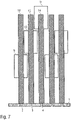
- figure 7 shows a modification of the embodiment according to FIG figure 4 , so that, in order to avoid repetition, reference is made to the above description, the same reference numbers being used for corresponding details.
- valve needles 12-14 have a uniform length and therefore also have a uniform mass. This is advantageous because the dynamic response behavior of the actuators 9-10 is not changed by different inertial masses.
- figure 8 shows a sectional view of an actuator 22 according to the invention with an armature 23 that can be displaced in the direction of the double arrow, a housing 24, a coil 25, a coil former 26 and a magnetic core 27.
- the movable armature 23 transmits its movement to a valve needle 29 via a hammer 28.
- figure 9 shows a schematic representation of a valve needle 30 with a valve needle tip 31 with an additional seal.
- a sealing membrane 32 is shown here, which separates a nozzle chamber 33 filled with coating agent from an actuator chamber 34 .
- the sealing membrane 32 prevents the coating agent from passing from the nozzle chamber 33 into the actuator chamber 34 and contaminating the actuators there.
- figure 10 shows an embodiment of the invention, in which an actuator 35 acts with its actuator needle 36 on five valve needles 37 and thus selectively closes or opens a plurality of nozzles 38 in a nozzle plate 39 .
- FIG figure 11 shows a modification of the embodiment according to FIG figure 10 .
- the actuator needle 36 acts on a sealing element 40 which then selectively releases or closes several of the nozzles 38 .
- figure 12 shows a modification of figure 8 , so that, in order to avoid repetition, reference is made to the above description, the same reference numbers being used for corresponding details.
- a special feature of this representation is that an adjustment device 41 is also shown in order to be able to adjust the position of the actuator 22 in the print head.
- figure 12 also an integrated contacting 43 for electrical contacting of the coil 25.
- figure 13 shows a modification of figure 12 , so that to avoid repetition, reference is made to the above description and the same reference numbers are used for the corresponding details.
- a special feature of this exemplary embodiment is that instead of the integrated electrical contact 43, a hole 44 is provided for electrical contact. The cable ends of the coil can be fed out of this hole.
- FIG 14 shows a schematic representation to clarify a second variant of the invention.
- nozzles 45 are arranged equidistantly along the nozzle row 46 at a specific nozzle spacing d.
- the nozzles 45 are released or closed by valve needles (not shown), with the individual valve needles being driven mechanically by actuators 47 .
- the actuators 47 are offset at different distances laterally next to the row of nozzles 46 with respect to the row of nozzles 46 . This allows the linear packing density of the actuators 47 is increased along the row of nozzles 46, so that the nozzle spacing d can also be reduced accordingly.
- figure 15 shows a schematic representation of the mechanical activation of a valve needle 48, which is passed through a sealing membrane 49 and with its valve needle tip 50 a nozzle 51 in a nozzle plate 52 either opens or closes.
- the valve needle 48 is controlled by two actuators 53, 54, which act on the nozzle needle 48 via a common lifting beam 55.
- the two actuators 53, 54 act on the outside of the lifting beam 55, while the lifting beam 55 acts on the nozzle needle 48 at its center.
- figure 16 shows a modification of figure 15 , so that, in order to avoid repetition, reference is made to the above description, the same reference numbers being used for corresponding details.
- a special feature of this exemplary embodiment is that the two actuators 53, 54 press the valve needle 48 into the closed position and pull it into the open position.
- figure 17 shows a modification of figures 15 and 16, so that to avoid repetition, reference is again made to the above description, with the same reference numbers being used for corresponding details.
- valve needle 48 is driven by a single actuator 56 via a one-sided rocker arm 57, with the rocker arm 57 being pivotably mounted in a support 58.
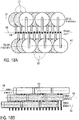
- FIGS. 18A and 18B show a modification of the embodiment according to FIG figure 6 , so that to avoid repetition, reference is also made to the above description.
- nozzles 59 are arranged equidistantly one behind the other in a nozzle row 60 .
- An actuator row 61, 62 is arranged on both sides of the nozzle row 60, specifically parallel to the nozzle row 60.
- the row of actuators 62 here comprises a plurality of actuators 63 which are arranged one above the other in three actuator planes 64, 65, 66, as shown in FIG Figure 18B is evident.
- the other row of actuators 61 also includes a plurality of actuators 67, which are also arranged one above the other in the three actuator levels 64-66.
- the actuators are arranged so that they are spatially equalized both horizontally (i.e. transversely to the row of nozzles 60) and vertically (i.e. perpendicularly to the plane of the nozzles). This enables the nozzle spacing between the adjacent nozzles 59 of the nozzle row 60 to be reduced.
- valve needles for the nozzles 59 of the nozzle row 60 are alternately connected to the actuators 67, 63 of the two actuator rows 61, 62.
- FIGS Figures 19A and 19B show a modification of the embodiment according to FIGS Figures 18A and 18B , so that, in order to avoid repetition, reference is made to the above description, the same reference numbers being used for corresponding details.
- a special feature of this exemplary embodiment is that the actuators 63, 67 are always connected in groups to the associated valve needles for the nozzles 59.
- the valve needles for the first three nozzles 59 of the row of nozzles 60 are controlled by the first three actuators 67 of the row of actuators 61 .
- the valve needles for the next three nozzles 59 in the nozzle row 60 are then controlled by the first three actuators 63 in the other actuator row 62 .
- figure 20 shows a schematic representation to explain the spatial rectification of actuators, both in the vertical direction (ie perpendicular to the nozzle plane) and in the horizontal direction (ie parallel to the nozzle plane).
- two rows of actuators are arranged parallel to one another and parallel to the row of nozzles in three actuator planes shown as examples one above the other.
- the right-hand actuator row includes two actuators a.1.1 and a.1.2, while the other actuator row has two actuators b.1.1 and b.1.2, for example.
- middle actuator level which also has two rows of actuators, each with two actuators a.2.1, a.2.2 or b.2.1 or b.2.2.
- the lower actuator level also contains two rows of actuators, each with two actuators a.3.1, a.3.2 or b.3.1, b.3.2, for example.
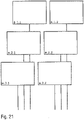
- figure 21 shows a modification of figure 20 , so that, in order to avoid repetition, reference is made to the above description, the same reference numbers being used for corresponding details.
- a special feature of this exemplary embodiment is that the actuators a.1.1, a.1.2, a.2.1, a.2.2, a.3.1, a.3.2 are spatially equalized only vertically, i.e. in three actuator levels one above the other. However, horizontal spatial equalization (i.e. across the row of nozzles) is not intended.
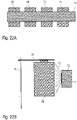
- FIGS. 22A and 22B show a schematic illustration for explaining the cooling of actuators 68-71 by compressed air 72, which flows out of a compressed air distributor 73 through a nozzle 74 and is directed onto the actuators 68-71 in order to cool the actuators 68-71.
- the individual actuators 68-71 each act on a valve needle 76 via a hammer 75.
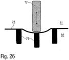
- FIGS. 23-25 show various possible configurations for the passage, connection or placement of valve needles 77 through a sealing membrane 78.
- valve needle 77 is continuous and thus forms with its nozzle closing tip 79 at the same time a sealing element for closing or releasing a corresponding valve seat.
- a sealing collar 80 is formed onto the sealing membrane 14 and protrudes from the sealing membrane 78 both towards an actuator chamber 81 and towards a nozzle chamber 82 .
- the nozzle sealing tip 79 is separated from the valve needle 77 and screwed to the valve needle 77.
- the sealing membrane 78 is pressed between the valve needle 77 and the nozzle closure tip 79, so that the valve needle 77 is firmly connected to the sealing membrane 78.
- a displacement of the valve needle 77 thus leads to a corresponding deflection of the sealing membrane 78.
- the sealing membrane 78 has no hole for the valve needle 77 to pass through. Rather, the nozzle closure tip 79 is formed integrally with the sealing membrane 78 .
- the valve needle 77 is firmly connected to the sealing membrane 78, so that a displacement of the valve needle 77 leads to a corresponding deflection of the sealing membrane 78.
- FIG 26 shows a sealing membrane 78 with molded nozzle sealing tips 79.
- the valve needle 77 can be connected to the sealing membrane 78, but it can also just be attached. If the valve needle 77 is only attached, the nozzle is opened by the paint pressure. The paint pressure deforms the sealing membrane 78 away from the nozzle chamber 82 in the direction of the actuator chamber 81 .
Landscapes
- Engineering & Computer Science (AREA)
- Manufacturing & Machinery (AREA)
- Chemical & Material Sciences (AREA)
- Materials Engineering (AREA)
- Organic Chemistry (AREA)
- Robotics (AREA)
- Mechanical Engineering (AREA)
- Coating Apparatus (AREA)
- Nozzles (AREA)
- Closures For Containers (AREA)
Claims (15)
- Applicateur, plus particulièrement tête d'impression, pour l'application d'un produit de revêtement, plus particulièrement d'une peinture, sur un composant, plus particulièrement sur un composant de carrosserie de véhicule automobile, aveca) au moins une rangée de buses (46) avec plusieurs buses (2-4 ; 38 ; 45 ; 51) pour la distribution du produit de revêtement sous la forme respectivement d'un jet, dans lequel les buses (2-4 ; 38 ; 45 ; 51) sont disposées le long de la rangée de buses (46) et dans un plan de buse commun etb) plusieurs actionneurs (9-11 ; 22 ; 35 ; 47 ; 53, 54 ; 56) reliés chacun avec un pointeau de soupape coulissant, pour la libération ou la fermeture contrôlée des buses (2-4 ; 38 ; 45 ; 51),c) dans lequel les différents actionneurs (9-11 ; 22 ; 35 ; 47 ; 53, 54 ; 56) comprennent chacun une dimension externe (b) le long de la rangée de buses (46), qui est supérieure à la distance entre les buses (d) le long de la rangée de buses (46) etd) un boîtier,
caractérisé en ce quee) le boîtier (24) est constitué de plusieurs parties de boîtier,f) les actionneurs (9-11 ; 22 ; 35 ; 47 ; 53, 54 ; 56) sont prévus respectivement pour moitié dans une des deux parties de boîtier etg) les pointeaux de soupapes (30) disposés parallèlement correspondent à une des deux parties du boîtier. - Applicateur selon la revendication 1, caractérisé en ce quea) les actionneurs (9-11) sont disposés à différentes distance et/ou orientations par rapport à la buse correspondante afin de permettre une faible distance entre les buses (d) des buses adjacentes (2-4) le long de la rangée de buses (46= et/oub) les actionneurs (9-11) sont disposés à différentes distances verticales par rapport à la rangée de buses, de manière superposée et/ouc) les actionneurs (9-11) sont à différentes distances horizontales par rapport à la rangée de buses, de manière juxtaposée et/oud) les actionneurs (9-11) sont disposés à des distances horizontales égales par rapport à la rangée de buses, de manière juxtaposée.
- Applicateur selon l'une des revendications précédentes, caractérisé en ce quea) les actionneurs sont disposés dans plusieurs plans d'actionneurs, dans lequel les différents plans d'actionneur s'étendent parallèlement au plan de buse etb) dans les différents plans d'actionneurs, sont disposées respectivement deux rangées d'actionneurs comprennent, des deux côtés de la rangée de buses, dans lequel les rangées d'actionneurs contiennent chacune plusieurs actionneurs.
- Applicateur selon la caractéristique b) de la revendication 2 et de la revendication 3, caractérisé en ce quea) les plans d'actionneurs adjacents verticalement présentent un décalage l'un par rapport à l'autre,b) le décalage entre les plans d'actionneurs adjacents verticalement est globalementb1) égal à la distance entre les buses (d) entre les buses adjacentes dans la rangée de buses oub2) est un multiple entier de la distance entre les buses (d) et/ouc) les actionneurs sont disposés de manière globalement équidistante dans les rangées d'actionneurs.
- Applicateur selon l'une des revendications précédentes, caractérisé en ce quea) les actionneurs comprennent chacun un pointeau d'actionneur coulissant,b) les buses peuvent être libérées ou fermées respectivement par les pointeaux d'actionneurs coulissants etc) les différents pointeaux d'actionneurs sont reliés chacun par un élément de liaison mécanique avec le pointeau de soupape correspondant, plus particulièrement par un bras ou un levier basculant pivotant d'un seul côté ou des deux côtés.
- Applicateur selon l'une des revendications 1 à 4, caractérisé en ce que les actionneurs comprennent chacun un pointeau d'actionneur coulissant, dans lequel le pointeau d'actionneur constitue le pointeau de soupape qui, en fonction de sa position, libère ou ferme la buse correspondante.
- Applicateur selon l'une des revendications précédentes, caractérisé en ce quea) les actionneurs sont immergés dans un fluide afin d'évacuer la chaleur dégagée lors du fonctionnement,b) l'évacuation du fluide a lieu par l'intermédiaire de l'intérieur du boîtier ouc) l'évacuation du fluide a lieu par l'intermédiaire de l'extérieur du boîtier.
- Applicateur selon l'une des revendications précédentes, caractérisé en ce que plusieurs, plus particulièrement deux, actionneurs (53, 54) agissent ensemble sur un pointeau de soupape (48), par l'intermédiaire d'une barre de levage commune (55), dans lequel les deux actionneurs (53, 54) agissent sur la barre de levage (55) et le pointeau de soupape (48) est entraîné par la barre de levage (55) au centre de la barre de levage (55).
- Applicateur selon l'une des revendications précédentes, caractérisé en ce quea) les actionneurs (9-11) sont reliés, en fonction de sa distance par rapport au plan de buse, avec des pointeaux de soupapes (12-14) de longueurs différentes, dans lequel les actionneurs (9-11) distants du plan de buse sont reliés avec un pointeau de soupape (12-14) plus long que les actionneurs (9-11) plus proches du plan de buse oub) les actionneurs (9-11)b1) sont tous reliés, indépendamment de leur distance par rapport au plan de buse, avec des pointeaux de soupape (12-14) de même longueur et/ou de même poids et/oub2) s'emboîtent, au niveau de points d'emboîtement, à différentes distance du plan de buse, avec les pointeaux de soupapes (12-14).
- Applicateur selon la revendication 9, caractérisé en ce quea) les pointeaux de soupapes (30) comprennent chacun une pointe de pointeau de soupape qui se rétrécit de manière conique en direction de leur extrémité libre etb) les différents pointeaux de soupapes (30) comprennent chacun, au niveau de leur pointe de pointeau de soupape, un élément d'étanchéité séparé etc) l'élément d'étanchéité séparéc1) est collé sur la pointe du pointeau de soupape ouc2) est maintenu dans une monture dans la pointe du pointeau de soupape ouc3) entoure la pointe du pointeau de soupape sur une partie de leur longueur etd) le pointeau de soupape (30) et l'élément d'étanchéité sont constitués de différents matériaux, plus particulièrement de métal pour le pointeau de soupape et de matière plastique pour l'élément d'étanchéité ete) l'élément d'étanchéité est fixé à la pointe du pointeau de soupape par :e1) un procédé de moulage par injection,e2) immersion,e3) soudure,e4) vulcanisation.
- Applicateur selon l'une des revendications 5 ou 6, caractérisé en ce quea) au moins un des pointeaux d'actionneurs (36) ferme ou libère plusieurs buses (38) et/oub) au moins un pointeau d'actionneur (36) pour la fermeture ou l'ouverture de plusieurs buses (38)b1) est relié avec plusieurs pointeaux de soupapes (37) oub2) est relié avec un élément d'étanchéité (40) qui ferme ou ouvre plusieurs des buses (38).
- Applicateur selon l'une des revendications précédentes, caractérisé en ce quea) aux différentes buses (2-4 ; 38 ; 45 ; 51) correspond respectivement un siège de soupape avec un élément d'étanchéité séparé etb) le siège de soupape est fermé ou libéré sélectivement par une pointe de pointeau de soupape,c) l'élément d'étanchéité dans le siège de soupape est constitué de métal ou d'un semi-métal etd) la pointe du pointeau de soupape est constitué d'un métal ou d'un semi-métal, de sorte que la pointe du pointeau de soupape et l'élément d'étanchéité du siège de soupape constituent une paire de matériaux métal - métal, métal - semi-métal, semi-métal - métal ou semi-métal - semi-métal.
- Applicateur selon l'une des revendications 5 ou 6, caractérisé en ce quea) le pointeau de soupape ou le pointeau d'actionneur est sollicité par un ressort de rappel et/oub) le ressort de rappel précontraint le pointeau de soupape ou le pointeau d'actionneur dans une position d'ouverture ou dans une position de fermeture.
- Robot de revêtement, plus particulièrement robot de peinture, avec un applicateur selon l'une des revendications précédentes.
- Robot de revêtement selon la revendication 14, caractérisé en ce que l'applicateur est fixé de manière interchangeable par un dispositif de changement rapide au robot de revêtement, plus particulièrement avec un tenon de serrage.
Applications Claiming Priority (2)
| Application Number | Priority Date | Filing Date | Title |
|---|---|---|---|
| DE102017122493.9A DE102017122493A1 (de) | 2017-09-27 | 2017-09-27 | Applikator mit geringem Düsenabstand |
| PCT/EP2018/075504 WO2019063417A1 (fr) | 2017-09-27 | 2018-09-20 | Applicateur à faible espacement entre les buses |
Publications (2)
| Publication Number | Publication Date |
|---|---|
| EP3687700A1 EP3687700A1 (fr) | 2020-08-05 |
| EP3687700B1 true EP3687700B1 (fr) | 2022-07-06 |
Family
ID=63685968
Family Applications (1)
| Application Number | Title | Priority Date | Filing Date |
|---|---|---|---|
| EP18778868.2A Active EP3687700B1 (fr) | 2017-09-27 | 2018-09-20 | Applicateur à interval de buses réduit |
Country Status (11)
| Country | Link |
|---|---|
| US (1) | US11673149B2 (fr) |
| EP (1) | EP3687700B1 (fr) |
| JP (1) | JP7181925B2 (fr) |
| KR (1) | KR102522866B1 (fr) |
| CN (1) | CN111148576B (fr) |
| DE (1) | DE102017122493A1 (fr) |
| ES (1) | ES2924691T3 (fr) |
| HU (1) | HUE059769T2 (fr) |
| MX (1) | MX2020003544A (fr) |
| PL (1) | PL3687700T3 (fr) |
| WO (1) | WO2019063417A1 (fr) |
Families Citing this family (8)
| Publication number | Priority date | Publication date | Assignee | Title |
|---|---|---|---|---|
| DE102021109850A1 (de) * | 2021-04-19 | 2022-10-20 | Vermes Microdispensing GmbH | Dosiermodul |
| DE102022103375A1 (de) | 2022-02-14 | 2023-08-17 | Dürr Systems Ag | Piezo-Aktorvorrichtung, vorzugsweise mit transversal auslenkbarer Düse |
| JP2023140940A (ja) | 2022-03-23 | 2023-10-05 | 株式会社リコー | 液滴吐出ヘッドおよび液滴吐出装置 |
| KR102753079B1 (ko) * | 2023-01-13 | 2025-01-14 | 이승구 | 마킹헤드 시스템 |
| IT202300002250A1 (it) * | 2023-02-09 | 2024-08-09 | Antonella Dolcini | Dispositivo per la smaltatura di oggetti |
| IT202300004104A1 (it) * | 2023-03-08 | 2024-09-08 | Durst Group Ag | "Testina di stampa per una stampante a getto d'inchiostro, in particolare per il rivestimento di supporti di stampa" |
| JP2025088261A (ja) | 2023-11-30 | 2025-06-11 | 株式会社リコー | 液体吐出ヘッド及び液体を吐出する装置 |
| DE102024118640B3 (de) | 2024-07-02 | 2025-08-21 | Dr. Ing. H.C. F. Porsche Aktiengesellschaft | Fluidkraftsystem mit einer Überwachungsvorrichtung, Lackiervorrichtung sowie Verfahren zum Detektieren von Volumenstromverlusten |
Family Cites Families (47)
| Publication number | Priority date | Publication date | Assignee | Title |
|---|---|---|---|---|
| US2296079A (en) * | 1939-01-23 | 1942-09-15 | Gen Mills Inc | Gluing head |
| US4128345A (en) | 1975-03-28 | 1978-12-05 | Universal Technology, Inc. | Fluid impulse matrix printer |
| US4157149A (en) * | 1977-10-31 | 1979-06-05 | Moen Lenard E | Multiple nozzle fluid dispenser for complex fluid delivery patterns |
| DE3302617C2 (de) * | 1983-01-27 | 1987-04-23 | Domino Printing Sciences Plc, Cambridge | Farbspritzkopf |
| DE3506393A1 (de) * | 1985-02-23 | 1986-08-28 | Windmöller & Hölscher, 4540 Lengerich | Leimauftragsvorrichtung |
| DE3624844A1 (de) * | 1986-07-23 | 1988-01-28 | Josef Schucker | Temperiergeraet fuer fluessige klebstoffe |
| DE3634137A1 (de) | 1986-10-07 | 1988-04-21 | Willett Int Ltd | Verfahren und vorrichtung zum diskontinuierlichen aufbringen eines aushaertenden stoffes auf einen gegenstand |
| GB8700203D0 (en) * | 1987-01-07 | 1987-02-11 | Domino Printing Sciences Plc | Ink jet printing head |
| US5022629A (en) * | 1988-01-04 | 1991-06-11 | Interface, Inc. | Valve construction |
| US5066216A (en) * | 1989-09-22 | 1991-11-19 | Binney & Smith Inc. | Apparatus for injection of viscous material |
| US5087930A (en) * | 1989-11-01 | 1992-02-11 | Tektronix, Inc. | Drop-on-demand ink jet print head |
| US5145689A (en) | 1990-10-17 | 1992-09-08 | Exxon Chemical Patents Inc. | Meltblowing die |
| JPH05293959A (ja) | 1992-04-22 | 1993-11-09 | Citizen Watch Co Ltd | インクジェットヘッド |
| US5769947A (en) | 1994-10-22 | 1998-06-23 | Itw Dynatech Gmbh Klebetechnik | Applicator for adhesive and corresponding nozzle plate |
| US5800614A (en) * | 1996-09-24 | 1998-09-01 | Foust; Paul William | Adhesive applier for screen printing machine |
| US7628468B2 (en) * | 1997-07-15 | 2009-12-08 | Silverbrook Research Pty Ltd | Nozzle with reciprocating plunger |
| JP2001146010A (ja) | 1999-11-18 | 2001-05-29 | Nec Corp | インクジェット記録ヘッド |
| CN1205035C (zh) * | 2000-05-24 | 2005-06-08 | 西尔弗布鲁克研究有限公司 | 带有外装控制器的移动喷嘴的喷墨打印头 |
| US20030131791A1 (en) | 2000-11-21 | 2003-07-17 | Schultz Carl L. | Multiple orifice applicator system and method of using same |
| US6776360B2 (en) * | 2001-06-26 | 2004-08-17 | Spraying Systems Co. | Spray gun with improved needle shut-off valve sealing arrangement |
| KR100439084B1 (ko) | 2001-11-15 | 2004-07-09 | 주식회사 프로텍 | 업다운 및 회전의 정밀제어가 가능한 고속정량토출형디스펜서 헤드 |
| BRPI0618255B1 (pt) | 2005-11-03 | 2020-10-06 | Spraying Systems Co | Conjunto de pulverização eletrostática |
| JP2007320042A (ja) * | 2006-05-30 | 2007-12-13 | Mimaki Engineering Co Ltd | 流体吐出装置および流体吐出装置群 |
| ITTV20060124A1 (it) | 2006-07-17 | 2008-01-18 | Hip Mitsu Srl | Struttura di testata di spalmatura, particolarmente di uno o piu' adesivi o miscele di adesivi |
| DE202006016377U1 (de) | 2006-10-20 | 2007-02-01 | Lincoln Gmbh | Schmiermittelverteiler |
| JP5059377B2 (ja) | 2006-11-08 | 2012-10-24 | 株式会社ニレコ | マーキングノズル装置 |
| EP1938911A1 (fr) | 2006-12-27 | 2008-07-02 | VAI Industries (UK) Ltd. | Dispositif et procédé pour refroidissement contrôlé |
| JP4643625B2 (ja) | 2007-09-25 | 2011-03-02 | 株式会社東芝 | 液滴噴射ヘッド |
| US20090107398A1 (en) | 2007-10-31 | 2009-04-30 | Nordson Corporation | Fluid dispensers and methods for dispensing viscous fluids with improved edge definition |
| EP2229282A1 (fr) | 2007-12-31 | 2010-09-22 | Exatec, LLC. | Appareil et procédé pour imprimer des articles tridimensionnels |
| DE102008053178A1 (de) * | 2008-10-24 | 2010-05-12 | Dürr Systems GmbH | Beschichtungseinrichtung und zugehöriges Beschichtungsverfahren |
| CN101480642B (zh) | 2008-12-30 | 2011-07-27 | 大连华工创新科技有限公司 | 多阀联动喷胶装置 |
| JP5328902B2 (ja) | 2009-05-18 | 2013-10-30 | 三菱電機株式会社 | ヒートポンプ装置 |
| CN201415168Y (zh) | 2009-07-16 | 2010-03-03 | 东莞市事通达机电科技有限公司 | 喷漆机械手使用的喷枪 |
| US8820871B2 (en) | 2010-10-27 | 2014-09-02 | Matthews Resources, Inc. | Valve jet printer with inert plunger tip |
| DE202010013054U1 (de) | 2010-12-03 | 2012-03-05 | Baumer Hhs Gmbh | Vorrichtung zum Auftragen von viskosen Medien |
| EP2734371B3 (fr) * | 2011-07-22 | 2023-08-23 | Durst Group AG | Tête d'impression pour imprimante à jet d'encre |
| JP2013107256A (ja) * | 2011-11-18 | 2013-06-06 | Seiko Epson Corp | 液体噴射ヘッド及び液体噴射装置 |
| DE112013001593B4 (de) | 2012-03-22 | 2022-11-10 | Kabushiki Kaisha Yaskawa Denki | Applikationsvorrichtung |
| DE102013208751A1 (de) * | 2013-05-13 | 2014-11-13 | Koenig & Bauer Aktiengesellschaft | Druckmaschine |
| CN104324866B (zh) * | 2013-07-22 | 2016-05-11 | 泰科电子(上海)有限公司 | 在工件的凹槽中注入密封胶的方法 |
| JP2015096322A (ja) * | 2013-10-07 | 2015-05-21 | 株式会社ミマキエンジニアリング | 印刷装置、インクジェットヘッド、及び印刷方法 |
| US10016977B2 (en) * | 2014-06-04 | 2018-07-10 | System S.P.A. | Device for the inkjet printing of fluids, in particular glazes, onto tiles |
| EP3194079B1 (fr) | 2014-08-15 | 2022-01-26 | dlhBowles Inc. | Buse de coupelle fluidique à plusieurs entrées et à plusieurs jets pulvérisés comprenant une zone d'interaction commune et procédé de production de jets pulvérisés |
| DE102014013158A1 (de) | 2014-09-11 | 2016-03-17 | Burkhard Büstgens | Freistrahl-Einrichtung |
| CN104647903B (zh) | 2015-02-09 | 2016-07-06 | 清华大学深圳研究生院 | 一种基于微流控芯片的打印喷头装置 |
| ES2960937T3 (es) * | 2017-03-31 | 2024-03-07 | Vaxxas Pty Ltd | Dispositivo y método para recubrir superficies |
-
2017
- 2017-09-27 DE DE102017122493.9A patent/DE102017122493A1/de not_active Withdrawn
-
2018
- 2018-09-20 EP EP18778868.2A patent/EP3687700B1/fr active Active
- 2018-09-20 KR KR1020207006081A patent/KR102522866B1/ko active Active
- 2018-09-20 WO PCT/EP2018/075504 patent/WO2019063417A1/fr not_active Ceased
- 2018-09-20 MX MX2020003544A patent/MX2020003544A/es unknown
- 2018-09-20 ES ES18778868T patent/ES2924691T3/es active Active
- 2018-09-20 CN CN201880062988.0A patent/CN111148576B/zh active Active
- 2018-09-20 US US16/649,217 patent/US11673149B2/en active Active
- 2018-09-20 PL PL18778868.2T patent/PL3687700T3/pl unknown
- 2018-09-20 JP JP2020518024A patent/JP7181925B2/ja active Active
- 2018-09-20 HU HUE18778868A patent/HUE059769T2/hu unknown
Also Published As
| Publication number | Publication date |
|---|---|
| DE102017122493A1 (de) | 2019-03-28 |
| ES2924691T3 (es) | 2022-10-10 |
| EP3687700A1 (fr) | 2020-08-05 |
| KR20200061333A (ko) | 2020-06-02 |
| US20200298254A1 (en) | 2020-09-24 |
| WO2019063417A1 (fr) | 2019-04-04 |
| KR102522866B1 (ko) | 2023-04-19 |
| US11673149B2 (en) | 2023-06-13 |
| JP2020535009A (ja) | 2020-12-03 |
| HUE059769T2 (hu) | 2022-12-28 |
| MX2020003544A (es) | 2020-07-29 |
| CN111148576A (zh) | 2020-05-12 |
| CN111148576B (zh) | 2022-05-31 |
| PL3687700T3 (pl) | 2022-11-14 |
| JP7181925B2 (ja) | 2022-12-01 |
Similar Documents
| Publication | Publication Date | Title |
|---|---|---|
| EP3687700B1 (fr) | Applicateur à interval de buses réduit | |
| EP2969248B1 (fr) | Soupape de dosage et procédé de dosage | |
| EP2118542B1 (fr) | Microsoupape | |
| EP3025358B1 (fr) | Dispositif de commande électromagnétique et système d'ajustement de fonctionnalité d'un composant de véhicule | |
| DE1817454C3 (de) | Servosteuerventil | |
| DE102012109123A1 (de) | Dosiersystem, Dosierverfahren und Herstellungsverfahren | |
| EP1179134A1 (fr) | Injecteur | |
| DE19714486C2 (de) | Vorrichtung zum Übertragen einer Auslenkung eines Aktors | |
| EP1118765A2 (fr) | Injecteur de combustible pour moteur à combustion interne | |
| WO2018108571A1 (fr) | Tête d'impression pourvue d'un dispositif de thermorégulation | |
| EP0600202A1 (fr) | Dispositif de commande de valve | |
| EP1623109A1 (fr) | Soupape d'injection de carburant | |
| DE202013101134U1 (de) | Dosierventil | |
| DE4236371C2 (de) | Vorrichtung und Verfahren zum Einspritzen | |
| EP3687699B1 (fr) | Applicateur muni d'une membrane étanche | |
| DE2119415B2 (de) | Elektromagnetischer Antrieb für die Nadel eines Nadeldruckers | |
| DE19503495A1 (de) | Spritzpistole mit ansetzbaren Düsenelementen | |
| EP4326448A1 (fr) | Module de dosage | |
| DE102017122495A1 (de) | Applikator mit einem geringen Düsenabstand | |
| DE69716628T2 (de) | Verfahren zum auftragen von tropfen einer flüssigkeit auf eine unterlage | |
| DE3249486A1 (de) | Nadelverschluss-duese fuer spritzgiessformen | |
| DE102012015083B3 (de) | Dispenserkopf mit mehreren verschiebbaren Dispensern | |
| DE4432867C2 (de) | Pneumatisch betriebene Zylindereinheit | |
| DE102023127687B3 (de) | Proportinalventil sowie Stoßdämpfer mit einem solchen Proportionalventil | |
| DE102006027327B4 (de) | Kraftstoffinjektor mit direkter Nadelsteuerung |
Legal Events
| Date | Code | Title | Description |
|---|---|---|---|
| STAA | Information on the status of an ep patent application or granted ep patent |
Free format text: STATUS: UNKNOWN |
|
| STAA | Information on the status of an ep patent application or granted ep patent |
Free format text: STATUS: THE INTERNATIONAL PUBLICATION HAS BEEN MADE |
|
| PUAI | Public reference made under article 153(3) epc to a published international application that has entered the european phase |
Free format text: ORIGINAL CODE: 0009012 |
|
| STAA | Information on the status of an ep patent application or granted ep patent |
Free format text: STATUS: REQUEST FOR EXAMINATION WAS MADE |
|
| 17P | Request for examination filed |
Effective date: 20200204 |
|
| AK | Designated contracting states |
Kind code of ref document: A1 Designated state(s): AL AT BE BG CH CY CZ DE DK EE ES FI FR GB GR HR HU IE IS IT LI LT LU LV MC MK MT NL NO PL PT RO RS SE SI SK SM TR |
|
| AX | Request for extension of the european patent |
Extension state: BA ME |
|
| DAV | Request for validation of the european patent (deleted) | ||
| DAX | Request for extension of the european patent (deleted) | ||
| GRAP | Despatch of communication of intention to grant a patent |
Free format text: ORIGINAL CODE: EPIDOSNIGR1 |
|
| STAA | Information on the status of an ep patent application or granted ep patent |
Free format text: STATUS: GRANT OF PATENT IS INTENDED |
|
| INTG | Intention to grant announced |
Effective date: 20220225 |
|
| GRAS | Grant fee paid |
Free format text: ORIGINAL CODE: EPIDOSNIGR3 |
|
| GRAA | (expected) grant |
Free format text: ORIGINAL CODE: 0009210 |
|
| STAA | Information on the status of an ep patent application or granted ep patent |
Free format text: STATUS: THE PATENT HAS BEEN GRANTED |
|
| AK | Designated contracting states |
Kind code of ref document: B1 Designated state(s): AL AT BE BG CH CY CZ DE DK EE ES FI FR GB GR HR HU IE IS IT LI LT LU LV MC MK MT NL NO PL PT RO RS SE SI SK SM TR |
|
| REG | Reference to a national code |
Ref country code: AT Ref legal event code: REF Ref document number: 1502473 Country of ref document: AT Kind code of ref document: T Effective date: 20220715 Ref country code: CH Ref legal event code: EP |
|
| REG | Reference to a national code |
Ref country code: DE Ref legal event code: R096 Ref document number: 502018010106 Country of ref document: DE |
|
| REG | Reference to a national code |
Ref country code: IE Ref legal event code: FG4D Free format text: LANGUAGE OF EP DOCUMENT: GERMAN |
|
| REG | Reference to a national code |
Ref country code: ES Ref legal event code: FG2A Ref document number: 2924691 Country of ref document: ES Kind code of ref document: T3 Effective date: 20221010 |
|
| REG | Reference to a national code |
Ref country code: LT Ref legal event code: MG9D |
|
| REG | Reference to a national code |
Ref country code: NL Ref legal event code: MP Effective date: 20220706 |
|
| REG | Reference to a national code |
Ref country code: SK Ref legal event code: T3 Ref document number: E 40599 Country of ref document: SK |
|
| REG | Reference to a national code |
Ref country code: HU Ref legal event code: AG4A Ref document number: E059769 Country of ref document: HU |
|
| PG25 | Lapsed in a contracting state [announced via postgrant information from national office to epo] |
Ref country code: SE Free format text: LAPSE BECAUSE OF FAILURE TO SUBMIT A TRANSLATION OF THE DESCRIPTION OR TO PAY THE FEE WITHIN THE PRESCRIBED TIME-LIMIT Effective date: 20220706 Ref country code: RS Free format text: LAPSE BECAUSE OF FAILURE TO SUBMIT A TRANSLATION OF THE DESCRIPTION OR TO PAY THE FEE WITHIN THE PRESCRIBED TIME-LIMIT Effective date: 20220706 Ref country code: PT Free format text: LAPSE BECAUSE OF FAILURE TO SUBMIT A TRANSLATION OF THE DESCRIPTION OR TO PAY THE FEE WITHIN THE PRESCRIBED TIME-LIMIT Effective date: 20221107 Ref country code: NO Free format text: LAPSE BECAUSE OF FAILURE TO SUBMIT A TRANSLATION OF THE DESCRIPTION OR TO PAY THE FEE WITHIN THE PRESCRIBED TIME-LIMIT Effective date: 20221006 Ref country code: NL Free format text: LAPSE BECAUSE OF FAILURE TO SUBMIT A TRANSLATION OF THE DESCRIPTION OR TO PAY THE FEE WITHIN THE PRESCRIBED TIME-LIMIT Effective date: 20220706 Ref country code: LV Free format text: LAPSE BECAUSE OF FAILURE TO SUBMIT A TRANSLATION OF THE DESCRIPTION OR TO PAY THE FEE WITHIN THE PRESCRIBED TIME-LIMIT Effective date: 20220706 Ref country code: LT Free format text: LAPSE BECAUSE OF FAILURE TO SUBMIT A TRANSLATION OF THE DESCRIPTION OR TO PAY THE FEE WITHIN THE PRESCRIBED TIME-LIMIT Effective date: 20220706 Ref country code: FI Free format text: LAPSE BECAUSE OF FAILURE TO SUBMIT A TRANSLATION OF THE DESCRIPTION OR TO PAY THE FEE WITHIN THE PRESCRIBED TIME-LIMIT Effective date: 20220706 |
|
| PG25 | Lapsed in a contracting state [announced via postgrant information from national office to epo] |
Ref country code: IS Free format text: LAPSE BECAUSE OF FAILURE TO SUBMIT A TRANSLATION OF THE DESCRIPTION OR TO PAY THE FEE WITHIN THE PRESCRIBED TIME-LIMIT Effective date: 20221106 Ref country code: HR Free format text: LAPSE BECAUSE OF FAILURE TO SUBMIT A TRANSLATION OF THE DESCRIPTION OR TO PAY THE FEE WITHIN THE PRESCRIBED TIME-LIMIT Effective date: 20220706 Ref country code: GR Free format text: LAPSE BECAUSE OF FAILURE TO SUBMIT A TRANSLATION OF THE DESCRIPTION OR TO PAY THE FEE WITHIN THE PRESCRIBED TIME-LIMIT Effective date: 20221007 |
|
| REG | Reference to a national code |
Ref country code: DE Ref legal event code: R097 Ref document number: 502018010106 Country of ref document: DE |
|
| PG25 | Lapsed in a contracting state [announced via postgrant information from national office to epo] |
Ref country code: SM Free format text: LAPSE BECAUSE OF FAILURE TO SUBMIT A TRANSLATION OF THE DESCRIPTION OR TO PAY THE FEE WITHIN THE PRESCRIBED TIME-LIMIT Effective date: 20220706 Ref country code: RO Free format text: LAPSE BECAUSE OF FAILURE TO SUBMIT A TRANSLATION OF THE DESCRIPTION OR TO PAY THE FEE WITHIN THE PRESCRIBED TIME-LIMIT Effective date: 20220706 Ref country code: MC Free format text: LAPSE BECAUSE OF FAILURE TO SUBMIT A TRANSLATION OF THE DESCRIPTION OR TO PAY THE FEE WITHIN THE PRESCRIBED TIME-LIMIT Effective date: 20220706 Ref country code: DK Free format text: LAPSE BECAUSE OF FAILURE TO SUBMIT A TRANSLATION OF THE DESCRIPTION OR TO PAY THE FEE WITHIN THE PRESCRIBED TIME-LIMIT Effective date: 20220706 |
|
| REG | Reference to a national code |
Ref country code: CH Ref legal event code: PL |
|
| PLBE | No opposition filed within time limit |
Free format text: ORIGINAL CODE: 0009261 |
|
| STAA | Information on the status of an ep patent application or granted ep patent |
Free format text: STATUS: NO OPPOSITION FILED WITHIN TIME LIMIT |
|
| REG | Reference to a national code |
Ref country code: BE Ref legal event code: MM Effective date: 20220930 |
|
| PG25 | Lapsed in a contracting state [announced via postgrant information from national office to epo] |
Ref country code: EE Free format text: LAPSE BECAUSE OF FAILURE TO SUBMIT A TRANSLATION OF THE DESCRIPTION OR TO PAY THE FEE WITHIN THE PRESCRIBED TIME-LIMIT Effective date: 20220706 |
|
| 26N | No opposition filed |
Effective date: 20230411 |
|
| P01 | Opt-out of the competence of the unified patent court (upc) registered |
Effective date: 20230512 |
|
| PG25 | Lapsed in a contracting state [announced via postgrant information from national office to epo] |
Ref country code: LU Free format text: LAPSE BECAUSE OF NON-PAYMENT OF DUE FEES Effective date: 20220920 Ref country code: AL Free format text: LAPSE BECAUSE OF FAILURE TO SUBMIT A TRANSLATION OF THE DESCRIPTION OR TO PAY THE FEE WITHIN THE PRESCRIBED TIME-LIMIT Effective date: 20220706 |
|
| PG25 | Lapsed in a contracting state [announced via postgrant information from national office to epo] |
Ref country code: LI Free format text: LAPSE BECAUSE OF NON-PAYMENT OF DUE FEES Effective date: 20220930 Ref country code: IE Free format text: LAPSE BECAUSE OF NON-PAYMENT OF DUE FEES Effective date: 20220920 Ref country code: CH Free format text: LAPSE BECAUSE OF NON-PAYMENT OF DUE FEES Effective date: 20220930 |
|
| PG25 | Lapsed in a contracting state [announced via postgrant information from national office to epo] |
Ref country code: SI Free format text: LAPSE BECAUSE OF FAILURE TO SUBMIT A TRANSLATION OF THE DESCRIPTION OR TO PAY THE FEE WITHIN THE PRESCRIBED TIME-LIMIT Effective date: 20220706 |
|
| PG25 | Lapsed in a contracting state [announced via postgrant information from national office to epo] |
Ref country code: BE Free format text: LAPSE BECAUSE OF NON-PAYMENT OF DUE FEES Effective date: 20220930 |
|
| PG25 | Lapsed in a contracting state [announced via postgrant information from national office to epo] |
Ref country code: CY Free format text: LAPSE BECAUSE OF FAILURE TO SUBMIT A TRANSLATION OF THE DESCRIPTION OR TO PAY THE FEE WITHIN THE PRESCRIBED TIME-LIMIT Effective date: 20220706 |
|
| PG25 | Lapsed in a contracting state [announced via postgrant information from national office to epo] |
Ref country code: MK Free format text: LAPSE BECAUSE OF FAILURE TO SUBMIT A TRANSLATION OF THE DESCRIPTION OR TO PAY THE FEE WITHIN THE PRESCRIBED TIME-LIMIT Effective date: 20220706 |
|
| PG25 | Lapsed in a contracting state [announced via postgrant information from national office to epo] |
Ref country code: BG Free format text: LAPSE BECAUSE OF FAILURE TO SUBMIT A TRANSLATION OF THE DESCRIPTION OR TO PAY THE FEE WITHIN THE PRESCRIBED TIME-LIMIT Effective date: 20220706 |
|
| PG25 | Lapsed in a contracting state [announced via postgrant information from national office to epo] |
Ref country code: MT Free format text: LAPSE BECAUSE OF FAILURE TO SUBMIT A TRANSLATION OF THE DESCRIPTION OR TO PAY THE FEE WITHIN THE PRESCRIBED TIME-LIMIT Effective date: 20220706 |
|
| REG | Reference to a national code |
Ref country code: AT Ref legal event code: MM01 Ref document number: 1502473 Country of ref document: AT Kind code of ref document: T Effective date: 20230920 |
|
| PG25 | Lapsed in a contracting state [announced via postgrant information from national office to epo] |
Ref country code: AT Free format text: LAPSE BECAUSE OF NON-PAYMENT OF DUE FEES Effective date: 20230920 |
|
| PG25 | Lapsed in a contracting state [announced via postgrant information from national office to epo] |
Ref country code: AT Free format text: LAPSE BECAUSE OF NON-PAYMENT OF DUE FEES Effective date: 20230920 |
|
| PGFP | Annual fee paid to national office [announced via postgrant information from national office to epo] |
Ref country code: DE Payment date: 20250919 Year of fee payment: 8 |
|
| PGFP | Annual fee paid to national office [announced via postgrant information from national office to epo] |
Ref country code: PL Payment date: 20250911 Year of fee payment: 8 Ref country code: TR Payment date: 20250915 Year of fee payment: 8 Ref country code: IT Payment date: 20250918 Year of fee payment: 8 |
|
| PGFP | Annual fee paid to national office [announced via postgrant information from national office to epo] |
Ref country code: HU Payment date: 20250922 Year of fee payment: 8 Ref country code: GB Payment date: 20250919 Year of fee payment: 8 |
|
| PGFP | Annual fee paid to national office [announced via postgrant information from national office to epo] |
Ref country code: FR Payment date: 20250922 Year of fee payment: 8 |
|
| PGFP | Annual fee paid to national office [announced via postgrant information from national office to epo] |
Ref country code: CZ Payment date: 20250916 Year of fee payment: 8 |
|
| PGFP | Annual fee paid to national office [announced via postgrant information from national office to epo] |
Ref country code: SK Payment date: 20250916 Year of fee payment: 8 |
|
| PGFP | Annual fee paid to national office [announced via postgrant information from national office to epo] |
Ref country code: ES Payment date: 20251030 Year of fee payment: 8 |
|
| PGFP | Annual fee paid to national office [announced via postgrant information from national office to epo] |
Ref country code: AT Payment date: 20260410 Year of fee payment: 5 |