EP3689128A1 - Klapprahmen eines rasenmähers - Google Patents
Klapprahmen eines rasenmähers Download PDFInfo
- Publication number
- EP3689128A1 EP3689128A1 EP19717746.2A EP19717746A EP3689128A1 EP 3689128 A1 EP3689128 A1 EP 3689128A1 EP 19717746 A EP19717746 A EP 19717746A EP 3689128 A1 EP3689128 A1 EP 3689128A1
- Authority
- EP
- European Patent Office
- Prior art keywords
- disc
- rotating
- fixing disc
- fixing
- mower
- Prior art date
- Legal status (The legal status is an assumption and is not a legal conclusion. Google has not performed a legal analysis and makes no representation as to the accuracy of the status listed.)
- Granted
Links
Images


Classifications
-
- A—HUMAN NECESSITIES
- A01—AGRICULTURE; FORESTRY; ANIMAL HUSBANDRY; HUNTING; TRAPPING; FISHING
- A01D—HARVESTING; MOWING
- A01D67/00—Undercarriages or frames specially adapted for harvesters or mowers; Mechanisms for adjusting the frame; Platforms
-
- A—HUMAN NECESSITIES
- A01—AGRICULTURE; FORESTRY; ANIMAL HUSBANDRY; HUNTING; TRAPPING; FISHING
- A01D—HARVESTING; MOWING
- A01D34/00—Mowers; Mowing apparatus of harvesters
- A01D34/01—Mowers; Mowing apparatus of harvesters characterised by features relating to the type of cutting apparatus
- A01D34/412—Mowers; Mowing apparatus of harvesters characterised by features relating to the type of cutting apparatus having rotating cutters
- A01D34/63—Mowers; Mowing apparatus of harvesters characterised by features relating to the type of cutting apparatus having rotating cutters having cutters rotating about a vertical axis
- A01D34/64—Mowers; Mowing apparatus of harvesters characterised by features relating to the type of cutting apparatus having rotating cutters having cutters rotating about a vertical axis mounted on a vehicle, e.g. a tractor, or drawn by an animal or a vehicle
- A01D34/66—Mowers; Mowing apparatus of harvesters characterised by features relating to the type of cutting apparatus having rotating cutters having cutters rotating about a vertical axis mounted on a vehicle, e.g. a tractor, or drawn by an animal or a vehicle with two or more cutters
- A01D34/661—Mounting means
-
- A—HUMAN NECESSITIES
- A01—AGRICULTURE; FORESTRY; ANIMAL HUSBANDRY; HUNTING; TRAPPING; FISHING
- A01D—HARVESTING; MOWING
- A01D34/00—Mowers; Mowing apparatus of harvesters
- A01D34/01—Mowers; Mowing apparatus of harvesters characterised by features relating to the type of cutting apparatus
- A01D34/412—Mowers; Mowing apparatus of harvesters characterised by features relating to the type of cutting apparatus having rotating cutters
- A01D34/63—Mowers; Mowing apparatus of harvesters characterised by features relating to the type of cutting apparatus having rotating cutters having cutters rotating about a vertical axis
- A01D34/76—Driving mechanisms for the cutters
-
- A—HUMAN NECESSITIES
- A01—AGRICULTURE; FORESTRY; ANIMAL HUSBANDRY; HUNTING; TRAPPING; FISHING
- A01D—HARVESTING; MOWING
- A01D69/00—Driving mechanisms or parts thereof for harvesters or mowers
-
- A—HUMAN NECESSITIES
- A01—AGRICULTURE; FORESTRY; ANIMAL HUSBANDRY; HUNTING; TRAPPING; FISHING
- A01D—HARVESTING; MOWING
- A01D2101/00—Lawn-mowers
Definitions
- the present invention relates to the technical field of mowers, and more particularly, to a mower folding-type chassis.
- mowers for aesthetic and recreational purposes.
- traditional mowers sold on the market are mainly divided into a riding-type, a pushed-type and a handheld-type.
- the riding-type mower is normally four-wheeled, allowing an operator to ride on. It's high-powered, highly-efficient and suitable for mowing large lawn areas such as a football field, a golf course or a city park.
- the pushed-type mower has lower power consumption and smaller size, thus being used for mowing smaller lawn areas such as greenbelts along roads.
- the handheld-type mower is smaller and portable, designed specifically for lawn areas that are very small or incapable of being touched by a large mower.
- the chassis is arranged at the bottom of the mower, wherein mowing blades are arranged in the chassis, and a driving motor is installed in the mower for driving the blades to rotate.
- a driving motor is installed in the mower for driving the blades to rotate.
- the purpose of the present invention is to solve the shortcomings in the prior art by providing a mower folding-type chassis.
- a fixing disc and at least one rotating disc connected with the fixing disc When mowing a lawn, the rotating discs can be rotated and unfolded relative to the fixing disc, thereby improving the mowing efficiency, and when the mower needs to be stored or transported, the rotating discs can be rotated and folded relative to the fixing disc, thus reducing the space occupation of the mower.
- a mower folding-type chassis comprising a fixing disc and at least one rotating disc rotationally connected with the fixing disc; the fixing disc is fixedly arranged at the bottom of the mower; mowing blades are respectively arranged within the fixing disc and the rotating disc; a driving device used for driving the mowing blades to rotate is arranged in the mower.
- the number of the rotating discs is two, and the two rotating discs are respectively rotationally connected with the fixing disc.
- the driving device comprises a plurality of driving motors, which are respectively arranged on the fixing disc and the rotating disc.
- the driving motors are respectively in transmission connection with the mowing blades in the fixing disc and the rotating disc.
- the driving device comprises a driving motor, and the mowing blades in the fixing disc and the rotating disc are respectively connected with a belt wheel.
- a belt is arranged between the belt wheel on the fixing disc and that on the rotating disc in a sleeved mode.
- the driving motor is in transmission connection with the belt wheel on the fixing disc.
- the rotating disc is rotationally connected with the fixing disc through a rotating arm.
- a lead-screw motor is arranged on the mower. An output end of the lead-screw motor is in transmission connection with a lead screw.
- a sliding block is arranged on the lead screw, and the sliding block is connected with a rocking bar. The rocking bar is connected with the rotating arm.
- the rotating disc is rotationally connected with the fixing disc through a rotating arm.
- a lead screw is arranged on the mower, and a sliding block is arranged on the lead screw.
- the sliding block is connected with a rocking bar, and the rocking bar is connected with the rotating arm.
- the end portion of the lead screw is connected with a handle seat, and a handle is rotationally connected with the handle seat.
- a handle fixing device is arranged on the lead screw, and a clamping groove matched with the handle is formed in the handle fixing device.
- the rotating disc is rotationally connected with the fixing disc through a rotating arm.
- a plurality of positioning holes is distributed in the rotating arm in the circumferential direction.
- a pin-dropping device is arranged on the mower, and a limiting pin is movably arranged in the pin-dropping device. The limiting pin and the positioning holes are interacted to limit the rotating arm.
- the rotating disc is rotationally connected with the fixing disc through a rotating arm.
- a gear is arranged at a position where the rotating arm and the fixing disc are connected.
- a gear motor is arranged on the mower. An output end of the gear motor is in transmission connection with the gear through a linkage shaft.
- the rotating disc is rotationally connected with the fixing disc through a rotating arm.
- a gear is arranged at a position where the rotating arm and the fixing disc are connected.
- the gear is connected with a linkage shaft, and one end of the linkage shaft that is far away from the gear is perpendicularly connected with a connecting arm.
- a holder rod is rotationally connected with one end of the connecting arm.
- a plurality of fixing grooves interacting with the holder rod is distributed in the mower along the circumferential direction.
- the rotating disc is rotationally connected with the fixing disc through a rotating arm.
- a mounting disc is arranged on the fixing disc, and a U-shaped groove is formed in the mounting disc.
- a locking device is arranged on the rotating arm, and the locking device comprises a fixing nut and a locking piece.
- One end of the fixing nut is connected with the rotating arm, and the other end of the fixing nut penetrates through an arc groove.
- An eccentric block is arranged on the locking device, and the eccentric block is rotationally connected with one end of the fixing nut that penetrates through the arc groove.
- the rotating disc is rotationally connected with the fixing disc through a rotating arm.
- the rotating arm is connected with a first saw-tooth fixing disc, and a second saw-tooth fixing disc interacting with the first saw-tooth fixing disc is arranged on the fixing disc.
- the abutted surfaces of the first saw-tooth fixing disc and the second saw-tooth fixing disc are respectively provided with a saw-tooth surface.
- a locking device is arranged on the fixing disc, and the locking device comprises a fixing nut and a locking piece. One end of the fixing nut is connected with the fixing disc, and the other end of the fixing nut penetrates through the fixing disc, the second saw-tooth fixing disc, the first saw-tooth fixing disc and the rotating arm.
- An eccentric block is arranged on the locking piece, and the eccentric block is rotationally connected with one end of the fixing nut that penetrates through the rotating arm.
- the eccentric block is abutted against the rotating arm, thereby enabling the first saw-tooth fixing disc and the second saw-tooth fixing disc to be closely attached.
- the rotating disc is rotationally connected with the fixing disc through a rotating arm.
- a limiting groove is formed in the fixing disc, and a guide groove is formed in the rotating arm.
- a locking device is arranged on the fixing disc, and the locking device comprises a fixing nut and a locking piece.
- One end of the fixing nut is connected with the fixing disc, and the other end of the fixing nut penetrates through the limiting groove and the guide groove.
- An eccentric block is arranged on the locking piece, and the eccentric block is rotationally connected with one end of the fixing nut that penetrates through the guide groove.
- the present invention has the following advantages: According to the mower folding-type chassis of the present invention, when mowing a lawn with the mower, the rotating discs can be rotated relative to the fixing disc, thereby enabling the rotating discs and the fixing disc to be transversely arranged side by side. Thus, the mowing area of mowing blades in the rotating discs and the fixing disc can be greatly increased, and the mowing efficiency can be significantly improved.
- the rotating discs can be rotated relative to the fixing disc so that the rotating discs and the fixing disc are arranged side by side in a longitudinal direction. At this point, the rotating discs can be partially or completely folded in the mower, thus reducing the space occupation of the mower so that the storage and transportation can be facilitated.
- the mower folding-type chassis of embodiment 1 is shown in Figures 1-7 , which comprises a fixing disc 2 and at least one rotating disc 3 rotationally connected with the fixing disc 2.
- the fixing disc 2 is fixedly arranged at the bottom of the mower 1.
- each rotating disc 3 is respectively rotationally connected with the fixing disc 2
- two of the rotating discs 3 are respectively rotationally connected with the fixing disc 2
- the rest of the rotating discs 3 are respectively rotationally connected with the rotating discs 3 that are connected with the fixing disc 2.
- the plurality of the rotating discs 3 is connected in series.
- the mower 1 of the present invention can be a pushed-type mower or a riding-type mower.
- the fixing disc 2 and the rotating disc 3 respectively comprise a shell 34.
- Mowing blades 4 are respectively arranged within the shells 34 of the fixing disc 2 and the rotating disc 3.
- the mowing blade 4 is transversely arranged in the shell 34, and a connecting shaft 35 is vertically arranged on the mowing blade 4.
- a bearing 36 interacting with the connecting shaft 35 is arranged on the shell 34.
- One end of the connecting shaft 35 is connected with the mowing blade 4, and the other end of the connecting shaft 35 extends into the bearing 36, thereby enabling the mowing blade 4 to be rotationally installed in the shell 34.
- a sleeve 37 is connected with the shell 34 of the fixing disc 2, and a connecting hole 38 is formed in the top end of the sleeve 37.
- the sleeve 37 is connected with a frame at the bottom of the mower 1 through the connecting hole 38.
- the fixing disc 2 is fixedly connected with the frame at the bottom of the mower 1 through the sleeve 37.
- a driving device used for driving the mowing blades 4 to rotate is arranged in the mower 1, and a grass-discharging hole is formed in the side surface or the top of the shell 34. When the mowing blades 4 are rotated, a wind pressure can be generated to blow the mowed grass out of the chassis.
- the driving device further comprises a plurality of driving motors 39, which are respectively arranged on the fixing disc 2 and the rotating disc 3.
- the driving motors 39 are respectively in transmission connection with the connecting shaft 35 of the mowing blade 4 in the fixing disc 2 and that in the rotating disc 3.
- the mowing blades 4 in the fixing disc 2 and the rotating disc 3 are driven by the driving motors 39 to rotate, thus conveniently mowing the lawn.
- the structure of the driving device can be various.
- the driving device comprises a driving motor 39, and the connecting shaft 35 of the mowing blade 4 in the fixing disc 2 and that in the rotating disc 3 penetrate through one end of the shells 34, and are respectively connected with a belt wheel 40.
- a belt is arranged between the belt wheel 40 on the fixing disc 2 and that on the rotating disc 3 in a sleeved mode.
- a through groove 41 allowing the belt to pass through is formed in the sleeve 37.
- the driving motor 39 is arranged either on the fixing disc 2 or on the frame at the bottom of the mower 1, and is rotationally connected with the belt wheel 40 on the fixing disc 2.
- a tensioning device is further arranged on the rotating arm 5.
- the tensioning device comprises a tensioning wheel and a spring.
- the tensioning wheel is rotationally connected with a connecting rod.
- a stop block is further arranged on the rotating arm 5, and the spring is located between the stop block and the connecting rod. In this way, the tensioning wheel is always abutted against the belt so that the belt is always kept in a tensioned state.
- Each rotating disc 3 is rotationally connected to the fixing disc 2 through a rotating arm 5, and the rotating arm 5 is connected to the center of the fixing disc 2.
- the rotating arm 5 is fixedly connected with the shell 34 of the rotating disc 3 through a bolt.
- the rotating arm 5 is sleeved outside the sleeve 37, and is rotationally connected with the sleeve 37.
- a sliding groove is formed in the rotating arm 5, and a bolt is arranged on the shell 34 of the fixing disc 2.
- the bolt penetrates through the shell 34 and the sliding groove, and is connected with a screw cap.
- the rotating arm 5 can rotate relative to the bolt.
- the sliding groove and the bolt Through the arrangement of the sliding groove and the bolt, a limiting function can be achieved when the rotating arm 5 is rotated, thus preventing the rotating arm 5 from excessively rotating or being separated from the sleeve 37.
- the number of the rotating discs 3 is two
- the number of the rotating arms 5 is also two.
- the two rotating arms 5 are arranged on the sleeve 37 in a stacked mode, and the two rotating arms are respectively provided with a sliding groove.
- two bolts are arranged on the shell 34 of the fixing disc 2.
- Gaskets 33 are respectively arranged between the shell 34 of the fixing disc 2 and the rotating arm 5, and between the screw cap and the rotating arm 5, thereby facilitating the rotation of the rotating arm 5.
- a lead-screw motor 7 is arranged on the mower 1, and an output end of the lead-screw motor 7 is connected with a lead screw 6 in a transmission mode.
- a lead screw seat matched with the lead screw 6 is arranged on the fixing disc 2, and a sliding block 8 is arranged on the lead screw 6.
- the sliding block 8 is connected with a rocking bar 9, and the rocking bar 9 is connected with the rotating arm 5.
- the lead-screw motor 7 can be a servo motor, a steering engine, or a motor capable of achieving the same function.
- the lead-screw motor 7 can be stopped at any time so that the sliding block 8 can be stopped at any position of the lead screw 6.
- the unfolding angle of the rotating disc 3 relative to the fixing disc 2 can be adjusted according to actual requirements.
- the rotating disc 3 is fixed relative to the fixing disc 2.
- the lead-screw motor 7 is initiated to rotate reversely, the rotating disc 3 is driven to fold and retract relative to the fixing disc 2. Namely, the rotational motion of the lead screw 6 is converted into the linear motion of the sliding block 8 by means of a ball screw 6.
- a plurality of rocking bars 9 is connected with the sliding block 8, and the plurality of rocking bars 9 is correspondingly connected with the plurality of rotating arms 5.
- the lead-screw motor 7 When the lead-screw motor 7 is initiated, the lead screw 6 is driven to rotate, enabling the sliding block 8 to move along the lead screw 6 towards the position where the fixing disc 2 is located.
- the plurality of rotating arms is driven to rotate simultaneously through the plurality of rocking bars 9, thereby enabling the rotating discs 3 to rotate around the fixing disc 2.
- the rotating discs 3 are unfolded relative to the fixing disc 2.
- the number of the lead-screw motors 7, the lead screws and the sliding blocks 8 can be greatly reduced.
- the rotating discs 3 can be respectively driven to unfold through a plurality of lead-screw motors 7, lead screws and sliding blocks 8.
- the rotating discs 3 when mowing a lawn with the mower 1, the rotating discs 3 can be rotated relative to the fixing disc 2, thereby enabling the rotating discs 3 and the fixing disc 2 to be transversely arranged side by side.
- the mowing area of mowing blades 4 in the rotating discs 3 and the fixing disc 2 can be greatly increased, and the mowing efficiency can be significantly improved.
- the rotating discs 3 can be rotated relative to the fixing disc 2 so that the rotating discs 3 and the fixing disc 2 are arranged side by side in a longitudinal direction. At this point, the rotating discs 3 can be partially or completely folded in the mower 1, thus reducing the space occupation of the mower 1 so that the storage and transportation can be facilitated.
- the mower folding-type chassis of embodiment 2 is shown in Figures 1-5 and 8-10 .
- the main structure of the mower folding-type chassis of embodiment 2 is the same as that of embodiment 1.
- What makes embodiment 2 differ from embodiment 1 is the following: a lead screw is arranged on the mower 1; the fixing disc 2 is provided with a lead screw seat matched with the lead screw 6; a sliding block 8 is arranged on the lead screw 6, and the sliding block 8 is connected with a rocking bar 9; the rocking bar 9 is connected with a rotating arm 5, and the end portion of the lead screw 6 is connected with a handle seat 11; a handle is rotationally connected with the handle seat 11, and a handle fixing device 12 is further arranged on the lead screw 6; a clamping groove 13 matched with the handle 10 is formed in the handle fixing device 12.
- the lead screw 6 is driven to rotate by rotating the handle 10.
- the lead screw 6 is rotated to enable the sliding block 8 to move along the screw rod 6 to the position where the fixing disc 2 is located.
- the rotating arm 5 is driven to rotate through the rocking bar 9, thereby enabling the rotating disc 3 to rotate around the fixing disc 2.
- the rotating disc 3 is unfolded relative to the fixing disc 2.
- the handle 10 is rotated and clamped subsequently in the clamping groove 13, thereby completing the adjustment.
- the rotating disc 3 is fixed relative to the fixing disc 2.
- the rotating disc 3 is driven to fold and retract relative to be fixing disc 2.
- a plurality of rocking bars 9 is connected with the sliding block 8, and the plurality of rocking bars 9 is correspondingly connected with the plurality of rotating arms 5.
- the handle 10 When the handle 10 is rotated, the lead screw 6 is driven to rotate, enabling the sliding block 8 to move along the lead screw 6 towards the position where the fixing disc 2 is located.
- the plurality of rotating arms is driven to rotate simultaneously through the plurality of rocking bars 9, thereby enabling the rotating discs 3 to rotate around the fixing disc 2.
- the rotating discs 3 are unfolded relative to the fixing disc 2.
- the number of the handles 10, the lead screws and the sliding blocks 8 can be greatly reduced.
- the rotating discs 3 can also be respectively driven to unfold through a plurality of handles 10, lead screws and sliding blocks 8.
- the mower folding-type chassis of embodiment 3 is shown in Figures 1-5 and 11-13 .
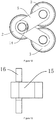
- the main structure of the mower folding-type chassis of embodiment 3 is the same as that of embodiment 1. The difference between them lies in: a plurality of positioning holes 14 is distributed on the rotating arm 5 along the circumferential direction; a pin-dropping device 15 is arranged on the mower 1, and a limiting pin 16 is movably arranged in the pin-dropping device 15; the limiting pin 16 interacts with the positioning holes 14 for limiting the rotating arm 5.
- the rotating disc 3 needs to be unfolded, the rotating disc 3 is rotated relative to the fixing disc 2.
- the limiting pin 16 When the unfolding angle of the rotating disc 3 relative to the fixing disc 2 satisfies the requirement of actual use, the limiting pin 16 is moved downwards, and is inserted into a positioning hole 14. Thus, the rotating arm 5 is limited, and the rotating disc 3 is fixed relative to the fixing disc 2. When the rotating disc 3 needs to be rotated again, the limiting pin 16 is pulled out and separated from the positioning hole 14. Thus, the rotating arm 5 is no longer limited, and the rotating disc 3 can be rotated again.
- the rotating arms 5 of the two rotating discs 3 connected with the fixing disc 2 are respectively provided with positioning holes in the same position, and the positioning holes in the two rotating arms 5 are partially overlapped.
- the two rotating discs 3 that are rotationally connected with the fixing disc 2 can be simultaneously fixed only by one pin-dropping device 15, and the two rotating discs 3 can be adjusted respectively.
- the rotating angles of the two rotating discs 3 relative to the fixing disc 2 can be different.
- the two rotating discs 3 can be respectively fixed through two pin-dropping devices 15.
- the rest of the rotating discs 3 are respectively fixed through pin-dropping devices 15.
- the interacting and adjusting modes are the same as the aforesaid, which are briefly described herein.
- the mower folding-type chassis of embodiment 4 is shown in Figures 1-5 and 14-16 .
- the main structure of the mower folding-type chassis of embodiment 4 is the same as that of embodiment 1. The difference between them is: the rotating disc 3 is rotationally connected with the fixing disc 2 through a rotating arm 5, and a gear 17 is arranged at a position where the rotating arm 5 and the fixing disc 2 are connected; a gear motor 19 is arranged on the mower 1, and the output end of the gear motor 19 is in transmission connection with the gear 17 through a linkage shaft 18.
- the gear motor 19 is initiated to rotate to drive the gear 17 to rotate through the linkage shaft 18, thereby enabling the rotating disc 3 to rotate relative to the fixing disc 2.
- the rotating disc 3 can be unfolded.
- the gear motor 19 can be stopped at any time so that the unfolding angle of the rotating disc 3 relative to the fixing disc 2 can be adjusted according to the requirement of actual use. At this point, the rotating disc 3 is fixed relative to the fixing disc 2. When the gear motor 19 is initiated to rotate reversely, the rotating disc 3 can be folded and retracted relative to the fixing disc 2.
- a connecting arm 20 is connected to the center of the fixing disc 2, and is arranged outside of the sleeve 37 in a sleeved mode.
- two of the rotating discs 3 are respectively rotationally connected with the fixing disc 2 through a rotating arm 5, and the rest of the rotating discs 3 are respectively rotationally connected with the rotating discs 3 that are connected with the fixing disc 2 through a rotating arm 5.
- the two rotating arms 5 are in eccentric connection with the shell 34 of the fixing disc 2, and two sleeves 37 are additionally arranged on the shell 34 of the fixing disc 2.
- the two rotating arms 5 are respectively arranged outside the two sleeves 37 in a sleeved mode.
- Gears 17 arranged on the two rotating arms 5 are meshed with each other.
- the rotation of the two rotating discs 3 connected with the fixing disc 2 can be achieved by only one gear motor 19.
- gears 17 arranged on the rotating arms 5 of the two rotating discs 3 connected with the fixing disc 2 are meshed with each other.
- the gear motor 19 only needs to be in transmission connection with one of the gears 17 through the linkage shaft 18, and both the two gears 17 can be driven to rotate.
- the number of the gear motors 19 can be reduced and the cost can be lowered.
- the distance between the two additionally-arranged sleeves 37 can be increased for preventing the gears 17 arranged on the two rotating arms 5 from interfering with each other.
- the gears 17 can be respectively driven to rotate by two gear motors 19, and the rest of the rotating discs 3 are respectively driven to rotate by a gear motor 19.
- the interacting and adjusting modes are the same as the aforesaid, which are briefly described herein.
- a tensioning device needs to be arranged on the rotating arm 5.
- the tensioning device comprises a tensioning wheel and a spring, and a connecting rod is rotationally connected to the tensioning wheel.
- a stop block is further arranged on the rotating arm 5.
- the spring is located between the stop block and the connecting rod, enabling the tensioning wheel to abut against the belt all the time.
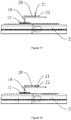
- the mower folding-type chassis of embodiment 5 is shown in Figures 1-5 and 17-18 .
- the main structure of the mower folding-type chassis of embodiment 5 is the same as that of embodiment 4.
- the difference between the two embodiments is: a gear is arranged at a position where the rotating arm 5 and the fixing disc 2 are connected; the gear 17 is connected with a linkage shaft 18; a connecting arm 20 is perpendicularly connected to one end of the linkage shaft 18 that is far away from the gear 17, and a holder rod 21 is rotationally connected to one end of the connecting arm 20; a plurality of fixing grooves 22 interacting with the holder rod 21 is distributed on the mower 1 along the circumferential direction.
- the holder rod 21 When the rotating disc 3 needs to be unfolded, the holder rod 21 is rotated to drive the gear 17 to rotate through the linkage shaft 18, thereby driving the rotating arm 5 to rotate.
- the rotating arm 5 further drives the rotating disc 3 to rotate relative to the fixing disc 2 so that the rotating disc 3 can be unfolded.
- the holder rod 21 When the unfolding angle of the rotating disc 3 relative to the fixing disc 2 satisfies the requirement of actual use, the holder rod 21 is rotated to be clamped within a fixing groove 22, thereby completing the adjustment. At this point, the rotating disc 3 is fixed relative to the fixing disc 2.
- the fixing groove 22 When the fixing groove 22 is rotated reversely, the rotating disc 3 is driven to fold and retract relative to the fixing disc 2.
- a connecting arm 20 is connected to the center of the fixing disc 2, and is arranged outside of the sleeve 37 in a sleeved mode.
- two of the rotating discs 3 are respectively rotationally connected with the fixing disc 2 through a rotating arm 5, and the rest of the rotating discs 3 are respectively rotationally connected with the rotating discs 3 that are connected with the fixing disc 2 through a rotating arm 5.
- the two rotating arms 5 are in eccentric connection with the shell 34 of the fixing disc 2, and two sleeves 37 are additionally arranged on the shell 34 of the fixing disc 2.
- the two rotating arms 5 are respectively arranged outside the two sleeves 37 in a sleeved mode.
- Gears 17 arranged on the two rotating arms 5 are meshed with each other.
- the rotation of the two rotating discs 3 connected with the fixing disc 2 can be achieved by only one gear motor 19.
- gears 17 arranged on the rotating arms 5 of the two rotating discs 3 connected with the fixing disc 2 are meshed with each other.
- the gear motor 19 can drive both the two gears 17 to rotate through a linkage shaft 18, a connecting arm 20 and a holder rod 21. According to this design, the cost can be greatly reduced.
- the distance between the two additionally-arranged sleeves 37 can be increased for preventing the gears 17 arranged on the two rotating arms 5 from interfering with each other, and the gears 17 can be respectively driven to rotate through a linkage shaft 18, a connecting arm 20 and a holder rod 21.
- the interacting and adjusting modes are the same as the aforesaid, which are briefly described herein.
- a tensioning device needs to be arranged on the rotating arm 5.
- the tensioning device comprises a tensioning wheel and a spring, and a connecting rod is rotationally connected to the tensioning wheel.
- a stop block is further arranged on the rotating arm 5.
- the spring is located between the stop block and the connecting rod, enabling the tensioning wheel to abut against the belt all the time.
- the mower folding-type chassis of embodiment 6 is shown in Figures 1-5 and 19-21 .
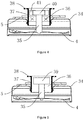
- the main structure of the mower folding-type chassis of embodiment 6 is the same as that of embodiment 1. The difference between them lies in: a mounting disc 23 is arranged on the fixing disc 2, and the mounting disc 23 is arranged outside the sleeve 37 in a sleeved mode; a U-shaped groove 24 is formed in the mounting disc 23; a locking device 25 is arranged on the rotating arm 5, and the locking device 25 comprises a fixing nut 26 and a locking piece 27; one end of the fixing nut 26 is connected to the rotating arm 5, and the other end of the fixing nut 26 penetrates through an arc groove; an eccentric block 28 is arranged on the locking piece 27, and the eccentric block 28 is rotationally connected to one end of the fixing nut 26 that penetrates through the arc groove.
- the eccentric block 28 When the locking piece 27 is rotated, the eccentric block 28 is abutted against the mounting disc 23, thereby enabling the mounting disc 23 to be closely attached to the rotating arm 5.
- the rotating disc 3 When the rotating disc 3 needs to be unfolded, the rotating disc 3 is rotated relative to the fixing disc 2. Once the unfolding angle of the rotating disc 3 relative to the fixing disc 2 satisfies the requirement of actual use, the locking piece 27 is rotated, and the eccentric block 28 is abutted against the mounting disc 23, thereby enabling the mounting disc 23 to be closely attached to the rotating arm 5.
- the rotating arm 5 is limited and the rotating disc 3 is fixed relative to the fixing disc 2.
- the locking piece 27 can be rotated reversely. In this way, the eccentric block 28 no longer is abutted against the mounting disc 23, and the rotating arm 5 is no longer limited so that the rotating disc 3 can be rotated again.
- the locking device 25 comprises a fixing nut 26 and a locking piece 27.
- One end of the fixing nut 26 is connected to the rotating arm 5, and the other end of the fixing nut 26 penetrates through an arc groove.
- An eccentric block 28 is arranged on the locking piece 27, and the eccentric block 28 is rotationally connected to one end of the fixing nut 26 that penetrates through the arc groove.
- the mower folding-type chassis of embodiment 7 is shown in Figures 1-5 and 22-24 .
- the main structure of the mower folding-type chassis of embodiment 7 is the same as that of embodiment 6. The difference between them lies in: a first saw-tooth fixing disc 29 is connected with the rotating arm 5, and a second saw-tooth fixing disc 30 interacting with the first saw-tooth fixing disc 29 is arranged on the fixing disc 2; the first saw-tooth fixing disc 29 and the second saw-tooth fixing disc 30 are arranged outside the sleeve 37 in a sleeved mode; the abutted surfaces of the first saw-tooth fixing disc 29 and the second saw-tooth fixing disc 30 are respectively provided with a saw-tooth surface; a locking device 25 is arranged on the fixing disc 2, and the locking device 25 comprises a fixing nut 26 and a locking piece 27; one end of the fixing nut 26 is connected with the fixing disc 2, and the other end of the fixing nut 26 penetrates through the fixing disc 2, the second saw-tooth fixing disc 30, the first
- the rotating disc 3 When the rotating disc 3 needs to be unfolded, the rotating disc 3 is rotated relative to the fixing disc 2, thereby enabling the first saw-tooth fixing disc 29 to rotate relative to the second saw-tooth fixing disc 30.
- the adjustment can be achieved.
- the unfolding angle of the rotating disc 3 relative to the fixing disc 2 satisfies the requirement of actual use, the locking piece 27 is rotated, and the eccentric block 28 is abutted against the rotating arm 5, thereby enabling the first saw-tooth fixing disc 29 to be closely attached to the second saw-tooth fixing disc 30.
- the rotating arm 5 is limited and the rotating disc 3 is fixed relative to the fixing disc 2.
- the locking piece 27 is rotated reversely.
- the eccentric block 28 is no longer abutted against the rotating arm 5, and the fist saw-tooth fixing disc 29 is not closely attached to the second saw-tooth fixing disc 30. At this point, the rotating arm 5 can be rotated relative to the fixing disc 2.
- the two rotating discs 3 are respectively connected to the center of the fixing disc 2 through a rotating arm 5.
- the rotating arm 5 of one rotating disc 3 that is rotationally connected with the fixing disc 2 is connected with a first saw-tooth fixing disc 29.
- a second saw-tooth fixing disc 30 interacting with the first saw-tooth fixing disc 29 is arranged on the fixing disc 2.
- a third saw-tooth fixing disc is further arranged on the other surface of the rotating arm 5 provided with the first saw-tooth fixing disc 29.
- a fourth saw-tooth fixing disc interacting with the third saw-tooth fixing disc is arranged on the rotating arm 5 of the other rotating disc 3 that is rotationally connected with the fixing disc 2.
- the first saw-tooth fixing disc 29, the second saw-tooth fixing disc 30, the third saw-tooth fixing disc and the fourth saw-tooth fixing disc are respectively provided with a saw-tooth surface. Moreover, the first saw-tooth fixing disc 29, the second saw-tooth fixing disc 30, the third saw-tooth fixing disc and the fourth saw-tooth fixing disc are respectively arranged outside the sleeve 37 in a sleeved mode.
- a locking device 25 is arranged on the fixing disc 2, and the locking device 25 comprises a fixing nut 26 and a locking piece 27.
- One end of the fixing nut 26 is connected with the fixing disc 2, and the other end of the fixing nut 26 penetrates through the fixing disc 2, the second saw-tooth fixing disc 30, the first saw-tooth fixing disc 29, the rotating arm 5 and the third saw-tooth fixing disc.
- An eccentric block 28 is arranged on the locking piece 27, the fourth saw-tooth fixing disc and the other rotating arm 5.
- the eccentric block 28 is rotationally connected with one end of the fixing nut 26 that penetrates through the other rotating arm 5.
- the eccentric block 28 is abutted against the rotating arm 5, thus enabling the first saw-tooth fixing disc 29, the second saw-tooth fixing disc 30, the third saw-tooth fixing disc and the fourth saw-tooth fixing disc to be closely attached.
- the rotating discs 3 that are rotationally connected with the fixing disc 2 are respectively provided with a saw-tooth fixing disc and a locking device 25, and the rotating arms 5 of the rest of the rotating discs that are connected with the rotating discs 3 connected with the fixing disc 2 are respectively provided with the other saw-tooth fixing disc interacting with the aforesaid saw-tooth fixing disc.
- the interacting and adjusting modes are the same as the aforesaid, which are briefly described herein.
- the mower folding-type chassis of embodiment 8 is shown in Figures 1-5 and 25-27 .
- the main structure of the mower folding-type chassis of embodiment 8 is the same as that of embodiment 6. The difference between them is: a limiting groove 31 is formed in the fixing disc 2, and a guide groove 32 is formed in the rotating arm 5; a locking device 25 is arranged on the fixing disc 2, and the locking device 25 comprises a fixing nut 26 and a locking piece 27; one end of the fixing nut 26 is connected with the fixing disc 2, and the other end of the fixing disc 26 penetrates through the limiting groove 31 and the guide groove 32.
- An eccentric block 28 is arranged on the locking piece 27, and the eccentric block 28 is rotationally connected to one end of the fixing nut 26 that penetrates through the guide groove 32.
- the eccentric block 28 When the locking piece 27 is rotated, the eccentric block 28 is abutted against the rotating arm 5, thereby enabling the rotating arm 5 to be closely attached to the fixing disc 2.
- one end of the fixing nut 26 that penetrates through the guide groove 32 is provided with a gasket 33.
- the eccentric block 28 is abutted against the rotating arm 5 through the gasket 33.
- the contact area is increased so that a tighter attachment can be achieved.
- the rotating disc 3 When the rotating disc 3 needs to be unfolded, the rotating disc 3 is rotated relative to the fixing disc 2. During the rotating process of the rotating disc 3, the fixing nut 26 moves along the limiting groove 31 through the guide groove 32. When the unfolding angle of the rotating disc 3 relative to the fixing disc 2 satisfies the requirement of actual use, the locking piece 27 is rotated, and the eccentric block 28 is abutted against the rotating arm 5, enabling the rotating arm 5 and the fixing disc 2 to be closely attached. Thus, the rotating disc 3 is fixed relative to the fixing disc 2. The mounting disc 23 is closely attached to the rotating arm 5, thereby limiting the rotating arm 5. Thus, the rotating disc 3 is fixed relative to the fixing disc 2. When the rotating disc 3 needs to be rotated again, the locking piece 27 is rotated reversely so that the eccentric block 28 is no longer abutted against the rotating arm 5. Thus, the rotating arm 5 is not limited and the rotating disc 3 can be rotated again.
- the other end of the fixing nut 26 penetrates through the limiting groove 31 and the two guide grooves 32, and is connected with the locking piece 27.
- the rotating discs 3 that are rotationally connected with the fixing disc 2 are respectively provided with a limiting groove 31 and a locking device 25, and the rotating arms 5 of rest of the rotating discs 3 are respectively provided with a guide groove 32.
- the fixing nut 26 penetrates through the limiting groove 31 and the guide groove 32, and is connected with the locking piece 27.
Landscapes
- Life Sciences & Earth Sciences (AREA)
- Environmental Sciences (AREA)
- Harvester Elements (AREA)
Applications Claiming Priority (2)
| Application Number | Priority Date | Filing Date | Title |
|---|---|---|---|
| CN201811486847.XA CN109526402B (zh) | 2018-12-06 | 2018-12-06 | 一种割草机折叠式底盘 |
| PCT/CN2019/071545 WO2020113777A1 (zh) | 2018-12-06 | 2019-01-14 | 一种割草机折叠式底盘 |
Publications (3)
| Publication Number | Publication Date |
|---|---|
| EP3689128A4 EP3689128A4 (de) | 2020-08-05 |
| EP3689128A1 true EP3689128A1 (de) | 2020-08-05 |
| EP3689128B1 EP3689128B1 (de) | 2022-03-16 |
Family
ID=65854173
Family Applications (1)
| Application Number | Title | Priority Date | Filing Date |
|---|---|---|---|
| EP19717746.2A Active EP3689128B1 (de) | 2018-12-06 | 2019-01-14 | Klapprahmen eines rasenmähers |
Country Status (4)
| Country | Link |
|---|---|
| US (1) | US20210400877A1 (de) |
| EP (1) | EP3689128B1 (de) |
| CN (3) | CN118216312A (de) |
| WO (1) | WO2020113777A1 (de) |
Cited By (1)
| Publication number | Priority date | Publication date | Assignee | Title |
|---|---|---|---|---|
| US11700790B2 (en) | 2019-05-17 | 2023-07-18 | Kubota Corporation | Grass mowing machine |
Families Citing this family (4)
| Publication number | Priority date | Publication date | Assignee | Title |
|---|---|---|---|---|
| IT201800009580A1 (it) * | 2018-10-18 | 2020-04-18 | Mdb Srl Con Socio Unico | Tagliaerba radiocomandato |
| US11785886B1 (en) * | 2020-09-01 | 2023-10-17 | Bad Boy Mowers, Llc | Zero-turn-radius riding mower front wheel positioning system |
| WO2026062548A1 (en) * | 2024-09-19 | 2026-03-26 | Free Green Nature S.r.l. | Grass-cutting equipment |
| CN119422611A (zh) * | 2024-11-12 | 2025-02-14 | 湖州职业技术学院 | 一种智能除草机 |
Family Cites Families (26)
| Publication number | Priority date | Publication date | Assignee | Title |
|---|---|---|---|---|
| GB190038A (en) * | 1922-01-14 | 1922-12-14 | Charles Frederick Webb | Improvements in foot operated pumps |
| GB564881A (en) * | 1943-07-28 | 1944-10-17 | Worcester Windshields & Caseme | Improvements relating to angularly-movable panels, such as vehicle windscreens |
| DE2115101A1 (de) * | 1971-03-29 | 1972-10-05 | Haseloff, Fritz, 3500 Kassel | Rasenmäher |
| US4024695A (en) * | 1974-03-08 | 1977-05-24 | Fritz Haseloff | Lawn mower |
| NL7905005A (nl) * | 1979-06-27 | 1980-12-30 | Vogelenzang Alexander J | Cirkelmaaier met variabele werkbreedte. |
| DE4407812A1 (de) * | 1994-03-09 | 1995-09-14 | Popiolek Franz M | Trommelmähmaschine |
| JPH07267358A (ja) * | 1994-03-31 | 1995-10-17 | Bando Chem Ind Ltd | 環状物の着脱装置 |
| JP3308949B2 (ja) * | 1999-11-10 | 2002-07-29 | タキゲン製造株式会社 | ファスナーロック装置 |
| US6702200B2 (en) * | 2001-07-24 | 2004-03-09 | The Board Of Regents For Oklahoma State University | Nozzle attitude controller for spot and variable rate application of agricultural chemicals and fertilizers |
| JP4324964B2 (ja) * | 2004-01-14 | 2009-09-02 | 株式会社アテックス | 自走式乗用草刈機 |
| FR2871077B1 (fr) * | 2004-06-02 | 2007-10-05 | Gyrax Soc Par Actions Simplifi | Broyeur a modules de broyage articules |
| JP5454865B2 (ja) * | 2009-03-31 | 2014-03-26 | 日立工機株式会社 | 芝刈機 |
| WO2010140929A1 (en) * | 2009-06-01 | 2010-12-09 | Andersson, Jonas | Lawn mower |
| WO2010140932A1 (en) * | 2009-06-02 | 2010-12-09 | Husqvarna Ab | Telescoping of cutting deck |
| DE102011080385B3 (de) * | 2011-06-10 | 2012-12-06 | Wiedenmann Gmbh | Mähdeck |
| KR101471037B1 (ko) * | 2013-04-11 | 2014-12-09 | 모영환 | 땅속 작물 수확기 |
| JP6542003B2 (ja) * | 2015-03-30 | 2019-07-10 | 中国電力株式会社 | 自走式作業用ロボット |
| CN106664964A (zh) * | 2017-03-02 | 2017-05-17 | 农业部南京农业机械化研究所 | 一种弹齿式棉花采摘装置 |
| CN207465216U (zh) * | 2017-09-14 | 2018-06-08 | 邵东智能制造技术研究院有限公司 | 一种简易轻便的机械手 |
| CN207252233U (zh) * | 2017-09-19 | 2018-04-20 | 浙江三锋实业股份有限公司 | 一种用于割草机的扶手高度调节机构 |
| CN108029325A (zh) * | 2017-12-31 | 2018-05-15 | 薛凤梧 | 割草覆盖还田机 |
| CN108124584A (zh) * | 2018-02-08 | 2018-06-08 | 北京时代沃林科技发展有限公司 | 一种新型避让式割草机 |
| CN108312141A (zh) * | 2018-04-13 | 2018-07-24 | 东北大学 | 一种送餐机器人的摆盘机械臂及使用方法 |
| CN209435831U (zh) * | 2018-12-06 | 2019-09-27 | 宁波朗辉工具有限公司 | 一种割草机折叠式底盘 |
| CN209914513U (zh) * | 2018-12-29 | 2020-01-10 | 宁波朗辉工具有限公司 | 一种割草机折叠式底盘结构 |
| CN113228926B (zh) * | 2021-05-27 | 2022-06-10 | 杭州生达轴承有限公司 | 一种自动避障割草设备 |
-
2018
- 2018-12-06 CN CN202410636582.6A patent/CN118216312A/zh active Pending
- 2018-12-06 CN CN201811486847.XA patent/CN109526402B/zh active Active
- 2018-12-06 CN CN202410636564.8A patent/CN118252028A/zh active Pending
-
2019
- 2019-01-14 WO PCT/CN2019/071545 patent/WO2020113777A1/zh not_active Ceased
- 2019-01-14 EP EP19717746.2A patent/EP3689128B1/de active Active
- 2019-01-14 US US16/325,643 patent/US20210400877A1/en not_active Abandoned
Cited By (1)
| Publication number | Priority date | Publication date | Assignee | Title |
|---|---|---|---|---|
| US11700790B2 (en) | 2019-05-17 | 2023-07-18 | Kubota Corporation | Grass mowing machine |
Also Published As
| Publication number | Publication date |
|---|---|
| CN109526402A (zh) | 2019-03-29 |
| CN118252028A (zh) | 2024-06-28 |
| US20210400877A1 (en) | 2021-12-30 |
| CN109526402B (zh) | 2024-06-07 |
| EP3689128A4 (de) | 2020-08-05 |
| CN118216312A (zh) | 2024-06-21 |
| EP3689128B1 (de) | 2022-03-16 |
| WO2020113777A1 (zh) | 2020-06-11 |
Similar Documents
| Publication | Publication Date | Title |
|---|---|---|
| EP3689128A1 (de) | Klapprahmen eines rasenmähers | |
| CN210470303U (zh) | 一种软轴传动全地形遥控割草机 | |
| CN102204479B (zh) | 一种茶园修边机 | |
| CA2616524A1 (en) | Power miter saw with hinge linkage linear guides | |
| WO2014150859A1 (en) | Power tool with brushless drive motor | |
| CN101850443B (zh) | 可调整切割角度的双锯片切割机 | |
| AU2023203270A1 (en) | Robotic garden tool with blade height adjustment | |
| CN220897273U (zh) | 多功能绿篱机 | |
| CN104170587B (zh) | 牧草收割机 | |
| CN210093955U (zh) | 一种独立割草装置 | |
| CN209914513U (zh) | 一种割草机折叠式底盘结构 | |
| CN209449233U (zh) | 一种便于存放的割草机 | |
| CN209546319U (zh) | 一种移动式市政园林用割草机 | |
| CN209435831U (zh) | 一种割草机折叠式底盘 | |
| CN206713413U (zh) | 一种高效自动割草机 | |
| JP6062313B2 (ja) | 多連モア | |
| US11950531B1 (en) | Trimmer attachment for lawn mower | |
| CN2760928Y (zh) | 手推式割草机 | |
| CN112021017B (zh) | 灌木修剪设备 | |
| CN108545113A (zh) | 绿篱机自动转向行走装置 | |
| AU2001100212A4 (en) | A pruning apparatus | |
| CN209497915U (zh) | 一种车载式移动割草设备 | |
| CN204047226U (zh) | 牧草收割机 | |
| CN223322495U (zh) | 一种园林绿化施工的园林割草机 | |
| WO2012030707A1 (en) | A power saw having a dual stage gear train |
Legal Events
| Date | Code | Title | Description |
|---|---|---|---|
| STAA | Information on the status of an ep patent application or granted ep patent |
Free format text: STATUS: UNKNOWN |
|
| STAA | Information on the status of an ep patent application or granted ep patent |
Free format text: STATUS: THE INTERNATIONAL PUBLICATION HAS BEEN MADE |
|
| PUAI | Public reference made under article 153(3) epc to a published international application that has entered the european phase |
Free format text: ORIGINAL CODE: 0009012 |
|
| STAA | Information on the status of an ep patent application or granted ep patent |
Free format text: STATUS: REQUEST FOR EXAMINATION WAS MADE |
|
| 17P | Request for examination filed |
Effective date: 20190426 |
|
| A4 | Supplementary search report drawn up and despatched |
Effective date: 20200317 |
|
| AK | Designated contracting states |
Kind code of ref document: A1 Designated state(s): AL AT BE BG CH CY CZ DE DK EE ES FI FR GB GR HR HU IE IS IT LI LT LU LV MC MK MT NL NO PL PT RO RS SE SI SK SM TR |
|
| AX | Request for extension of the european patent |
Extension state: BA ME |
|
| STAA | Information on the status of an ep patent application or granted ep patent |
Free format text: STATUS: EXAMINATION IS IN PROGRESS |
|
| 17Q | First examination report despatched |
Effective date: 20201218 |
|
| GRAP | Despatch of communication of intention to grant a patent |
Free format text: ORIGINAL CODE: EPIDOSNIGR1 |
|
| STAA | Information on the status of an ep patent application or granted ep patent |
Free format text: STATUS: GRANT OF PATENT IS INTENDED |
|
| DAV | Request for validation of the european patent (deleted) | ||
| DAX | Request for extension of the european patent (deleted) | ||
| INTG | Intention to grant announced |
Effective date: 20210714 |
|
| GRAS | Grant fee paid |
Free format text: ORIGINAL CODE: EPIDOSNIGR3 |
|
| GRAA | (expected) grant |
Free format text: ORIGINAL CODE: 0009210 |
|
| STAA | Information on the status of an ep patent application or granted ep patent |
Free format text: STATUS: THE PATENT HAS BEEN GRANTED |
|
| AK | Designated contracting states |
Kind code of ref document: B1 Designated state(s): AL AT BE BG CH CY CZ DE DK EE ES FI FR GB GR HR HU IE IS IT LI LT LU LV MC MK MT NL NO PL PT RO RS SE SI SK SM TR |
|
| REG | Reference to a national code |
Ref country code: GB Ref legal event code: FG4D |
|
| RIN1 | Information on inventor provided before grant (corrected) |
Inventor name: ZHAO, YANHUI |
|
| REG | Reference to a national code |
Ref country code: CH Ref legal event code: EP Ref country code: DE Ref legal event code: R096 Ref document number: 602019012620 Country of ref document: DE |
|
| REG | Reference to a national code |
Ref country code: IE Ref legal event code: FG4D |
|
| REG | Reference to a national code |
Ref country code: AT Ref legal event code: REF Ref document number: 1475240 Country of ref document: AT Kind code of ref document: T Effective date: 20220415 |
|
| REG | Reference to a national code |
Ref country code: LT Ref legal event code: MG9D |
|
| REG | Reference to a national code |
Ref country code: NL Ref legal event code: MP Effective date: 20220316 |
|
| PG25 | Lapsed in a contracting state [announced via postgrant information from national office to epo] |
Ref country code: SE Free format text: LAPSE BECAUSE OF FAILURE TO SUBMIT A TRANSLATION OF THE DESCRIPTION OR TO PAY THE FEE WITHIN THE PRESCRIBED TIME-LIMIT Effective date: 20220316 Ref country code: RS Free format text: LAPSE BECAUSE OF FAILURE TO SUBMIT A TRANSLATION OF THE DESCRIPTION OR TO PAY THE FEE WITHIN THE PRESCRIBED TIME-LIMIT Effective date: 20220316 Ref country code: NO Free format text: LAPSE BECAUSE OF FAILURE TO SUBMIT A TRANSLATION OF THE DESCRIPTION OR TO PAY THE FEE WITHIN THE PRESCRIBED TIME-LIMIT Effective date: 20220616 Ref country code: LT Free format text: LAPSE BECAUSE OF FAILURE TO SUBMIT A TRANSLATION OF THE DESCRIPTION OR TO PAY THE FEE WITHIN THE PRESCRIBED TIME-LIMIT Effective date: 20220316 Ref country code: HR Free format text: LAPSE BECAUSE OF FAILURE TO SUBMIT A TRANSLATION OF THE DESCRIPTION OR TO PAY THE FEE WITHIN THE PRESCRIBED TIME-LIMIT Effective date: 20220316 Ref country code: BG Free format text: LAPSE BECAUSE OF FAILURE TO SUBMIT A TRANSLATION OF THE DESCRIPTION OR TO PAY THE FEE WITHIN THE PRESCRIBED TIME-LIMIT Effective date: 20220616 |
|
| REG | Reference to a national code |
Ref country code: AT Ref legal event code: MK05 Ref document number: 1475240 Country of ref document: AT Kind code of ref document: T Effective date: 20220316 |
|
| PG25 | Lapsed in a contracting state [announced via postgrant information from national office to epo] |
Ref country code: LV Free format text: LAPSE BECAUSE OF FAILURE TO SUBMIT A TRANSLATION OF THE DESCRIPTION OR TO PAY THE FEE WITHIN THE PRESCRIBED TIME-LIMIT Effective date: 20220316 Ref country code: GR Free format text: LAPSE BECAUSE OF FAILURE TO SUBMIT A TRANSLATION OF THE DESCRIPTION OR TO PAY THE FEE WITHIN THE PRESCRIBED TIME-LIMIT Effective date: 20220617 Ref country code: FI Free format text: LAPSE BECAUSE OF FAILURE TO SUBMIT A TRANSLATION OF THE DESCRIPTION OR TO PAY THE FEE WITHIN THE PRESCRIBED TIME-LIMIT Effective date: 20220316 |
|
| PG25 | Lapsed in a contracting state [announced via postgrant information from national office to epo] |
Ref country code: NL Free format text: LAPSE BECAUSE OF FAILURE TO SUBMIT A TRANSLATION OF THE DESCRIPTION OR TO PAY THE FEE WITHIN THE PRESCRIBED TIME-LIMIT Effective date: 20220316 |
|
| PG25 | Lapsed in a contracting state [announced via postgrant information from national office to epo] |
Ref country code: SM Free format text: LAPSE BECAUSE OF FAILURE TO SUBMIT A TRANSLATION OF THE DESCRIPTION OR TO PAY THE FEE WITHIN THE PRESCRIBED TIME-LIMIT Effective date: 20220316 Ref country code: SK Free format text: LAPSE BECAUSE OF FAILURE TO SUBMIT A TRANSLATION OF THE DESCRIPTION OR TO PAY THE FEE WITHIN THE PRESCRIBED TIME-LIMIT Effective date: 20220316 Ref country code: RO Free format text: LAPSE BECAUSE OF FAILURE TO SUBMIT A TRANSLATION OF THE DESCRIPTION OR TO PAY THE FEE WITHIN THE PRESCRIBED TIME-LIMIT Effective date: 20220316 Ref country code: PT Free format text: LAPSE BECAUSE OF FAILURE TO SUBMIT A TRANSLATION OF THE DESCRIPTION OR TO PAY THE FEE WITHIN THE PRESCRIBED TIME-LIMIT Effective date: 20220718 Ref country code: ES Free format text: LAPSE BECAUSE OF FAILURE TO SUBMIT A TRANSLATION OF THE DESCRIPTION OR TO PAY THE FEE WITHIN THE PRESCRIBED TIME-LIMIT Effective date: 20220316 Ref country code: EE Free format text: LAPSE BECAUSE OF FAILURE TO SUBMIT A TRANSLATION OF THE DESCRIPTION OR TO PAY THE FEE WITHIN THE PRESCRIBED TIME-LIMIT Effective date: 20220316 Ref country code: CZ Free format text: LAPSE BECAUSE OF FAILURE TO SUBMIT A TRANSLATION OF THE DESCRIPTION OR TO PAY THE FEE WITHIN THE PRESCRIBED TIME-LIMIT Effective date: 20220316 Ref country code: AT Free format text: LAPSE BECAUSE OF FAILURE TO SUBMIT A TRANSLATION OF THE DESCRIPTION OR TO PAY THE FEE WITHIN THE PRESCRIBED TIME-LIMIT Effective date: 20220316 |
|
| PG25 | Lapsed in a contracting state [announced via postgrant information from national office to epo] |
Ref country code: PL Free format text: LAPSE BECAUSE OF FAILURE TO SUBMIT A TRANSLATION OF THE DESCRIPTION OR TO PAY THE FEE WITHIN THE PRESCRIBED TIME-LIMIT Effective date: 20220316 Ref country code: IS Free format text: LAPSE BECAUSE OF FAILURE TO SUBMIT A TRANSLATION OF THE DESCRIPTION OR TO PAY THE FEE WITHIN THE PRESCRIBED TIME-LIMIT Effective date: 20220716 Ref country code: AL Free format text: LAPSE BECAUSE OF FAILURE TO SUBMIT A TRANSLATION OF THE DESCRIPTION OR TO PAY THE FEE WITHIN THE PRESCRIBED TIME-LIMIT Effective date: 20220316 |
|
| REG | Reference to a national code |
Ref country code: DE Ref legal event code: R097 Ref document number: 602019012620 Country of ref document: DE |
|
| PLBE | No opposition filed within time limit |
Free format text: ORIGINAL CODE: 0009261 |
|
| STAA | Information on the status of an ep patent application or granted ep patent |
Free format text: STATUS: NO OPPOSITION FILED WITHIN TIME LIMIT |
|
| PG25 | Lapsed in a contracting state [announced via postgrant information from national office to epo] |
Ref country code: DK Free format text: LAPSE BECAUSE OF FAILURE TO SUBMIT A TRANSLATION OF THE DESCRIPTION OR TO PAY THE FEE WITHIN THE PRESCRIBED TIME-LIMIT Effective date: 20220316 |
|
| 26N | No opposition filed |
Effective date: 20221219 |
|
| PG25 | Lapsed in a contracting state [announced via postgrant information from national office to epo] |
Ref country code: SI Free format text: LAPSE BECAUSE OF FAILURE TO SUBMIT A TRANSLATION OF THE DESCRIPTION OR TO PAY THE FEE WITHIN THE PRESCRIBED TIME-LIMIT Effective date: 20220316 |
|
| PGFP | Annual fee paid to national office [announced via postgrant information from national office to epo] |
Ref country code: FR Payment date: 20230123 Year of fee payment: 5 |
|
| PGFP | Annual fee paid to national office [announced via postgrant information from national office to epo] |
Ref country code: DE Payment date: 20221202 Year of fee payment: 5 |
|
| PG25 | Lapsed in a contracting state [announced via postgrant information from national office to epo] |
Ref country code: IT Free format text: LAPSE BECAUSE OF FAILURE TO SUBMIT A TRANSLATION OF THE DESCRIPTION OR TO PAY THE FEE WITHIN THE PRESCRIBED TIME-LIMIT Effective date: 20220316 |
|
| REG | Reference to a national code |
Ref country code: CH Ref legal event code: PL |
|
| GBPC | Gb: european patent ceased through non-payment of renewal fee |
Effective date: 20230114 |
|
| PG25 | Lapsed in a contracting state [announced via postgrant information from national office to epo] |
Ref country code: LU Free format text: LAPSE BECAUSE OF NON-PAYMENT OF DUE FEES Effective date: 20230114 |
|
| REG | Reference to a national code |
Ref country code: BE Ref legal event code: MM Effective date: 20230131 |
|
| REG | Reference to a national code |
Ref country code: DE Ref legal event code: R082 Ref document number: 602019012620 Country of ref document: DE Representative=s name: SUN, YIMING, M.SC. DIPL. SC. POL. UNIV., DE |
|
| PG25 | Lapsed in a contracting state [announced via postgrant information from national office to epo] |
Ref country code: LI Free format text: LAPSE BECAUSE OF NON-PAYMENT OF DUE FEES Effective date: 20230131 Ref country code: GB Free format text: LAPSE BECAUSE OF NON-PAYMENT OF DUE FEES Effective date: 20230114 Ref country code: CH Free format text: LAPSE BECAUSE OF NON-PAYMENT OF DUE FEES Effective date: 20230131 |
|
| PG25 | Lapsed in a contracting state [announced via postgrant information from national office to epo] |
Ref country code: BE Free format text: LAPSE BECAUSE OF NON-PAYMENT OF DUE FEES Effective date: 20230131 |
|
| PG25 | Lapsed in a contracting state [announced via postgrant information from national office to epo] |
Ref country code: IE Free format text: LAPSE BECAUSE OF NON-PAYMENT OF DUE FEES Effective date: 20230114 |
|
| PG25 | Lapsed in a contracting state [announced via postgrant information from national office to epo] |
Ref country code: MC Free format text: LAPSE BECAUSE OF FAILURE TO SUBMIT A TRANSLATION OF THE DESCRIPTION OR TO PAY THE FEE WITHIN THE PRESCRIBED TIME-LIMIT Effective date: 20220316 |
|
| PG25 | Lapsed in a contracting state [announced via postgrant information from national office to epo] |
Ref country code: MC Free format text: LAPSE BECAUSE OF FAILURE TO SUBMIT A TRANSLATION OF THE DESCRIPTION OR TO PAY THE FEE WITHIN THE PRESCRIBED TIME-LIMIT Effective date: 20220316 |
|
| REG | Reference to a national code |
Ref country code: DE Ref legal event code: R119 Ref document number: 602019012620 Country of ref document: DE |
|
| PG25 | Lapsed in a contracting state [announced via postgrant information from national office to epo] |
Ref country code: DE Free format text: LAPSE BECAUSE OF NON-PAYMENT OF DUE FEES Effective date: 20240801 |
|
| PG25 | Lapsed in a contracting state [announced via postgrant information from national office to epo] |
Ref country code: FR Free format text: LAPSE BECAUSE OF NON-PAYMENT OF DUE FEES Effective date: 20240131 |
|
| PG25 | Lapsed in a contracting state [announced via postgrant information from national office to epo] |
Ref country code: FR Free format text: LAPSE BECAUSE OF NON-PAYMENT OF DUE FEES Effective date: 20240131 Ref country code: DE Free format text: LAPSE BECAUSE OF NON-PAYMENT OF DUE FEES Effective date: 20240801 |
|
| PG25 | Lapsed in a contracting state [announced via postgrant information from national office to epo] |
Ref country code: CY Free format text: LAPSE BECAUSE OF FAILURE TO SUBMIT A TRANSLATION OF THE DESCRIPTION OR TO PAY THE FEE WITHIN THE PRESCRIBED TIME-LIMIT; INVALID AB INITIO Effective date: 20190114 |
|
| PG25 | Lapsed in a contracting state [announced via postgrant information from national office to epo] |
Ref country code: HU Free format text: LAPSE BECAUSE OF FAILURE TO SUBMIT A TRANSLATION OF THE DESCRIPTION OR TO PAY THE FEE WITHIN THE PRESCRIBED TIME-LIMIT; INVALID AB INITIO Effective date: 20190114 |
|
| PG25 | Lapsed in a contracting state [announced via postgrant information from national office to epo] |
Ref country code: TR Free format text: LAPSE BECAUSE OF FAILURE TO SUBMIT A TRANSLATION OF THE DESCRIPTION OR TO PAY THE FEE WITHIN THE PRESCRIBED TIME-LIMIT Effective date: 20220316 |