EP3689128B1 - Klapprahmen eines rasenmähers - Google Patents
Klapprahmen eines rasenmähers Download PDFInfo
- Publication number
- EP3689128B1 EP3689128B1 EP19717746.2A EP19717746A EP3689128B1 EP 3689128 B1 EP3689128 B1 EP 3689128B1 EP 19717746 A EP19717746 A EP 19717746A EP 3689128 B1 EP3689128 B1 EP 3689128B1
- Authority
- EP
- European Patent Office
- Prior art keywords
- rotating
- fixing disc
- disc
- mower
- rotating discs
- Prior art date
- Legal status (The legal status is an assumption and is not a legal conclusion. Google has not performed a legal analysis and makes no representation as to the accuracy of the status listed.)
- Active
Links
- 0 CC1(*)CC=CC1 Chemical compound CC1(*)CC=CC1 0.000 description 1
Images


Classifications
-
- A—HUMAN NECESSITIES
- A01—AGRICULTURE; FORESTRY; ANIMAL HUSBANDRY; HUNTING; TRAPPING; FISHING
- A01D—HARVESTING; MOWING
- A01D34/00—Mowers; Mowing apparatus of harvesters
- A01D34/01—Mowers; Mowing apparatus of harvesters characterised by features relating to the type of cutting apparatus
- A01D34/412—Mowers; Mowing apparatus of harvesters characterised by features relating to the type of cutting apparatus having rotating cutters
- A01D34/63—Mowers; Mowing apparatus of harvesters characterised by features relating to the type of cutting apparatus having rotating cutters having cutters rotating about a vertical axis
- A01D34/64—Mowers; Mowing apparatus of harvesters characterised by features relating to the type of cutting apparatus having rotating cutters having cutters rotating about a vertical axis mounted on a vehicle, e.g. a tractor, or drawn by an animal or a vehicle
- A01D34/66—Mowers; Mowing apparatus of harvesters characterised by features relating to the type of cutting apparatus having rotating cutters having cutters rotating about a vertical axis mounted on a vehicle, e.g. a tractor, or drawn by an animal or a vehicle with two or more cutters
-
- A—HUMAN NECESSITIES
- A01—AGRICULTURE; FORESTRY; ANIMAL HUSBANDRY; HUNTING; TRAPPING; FISHING
- A01D—HARVESTING; MOWING
- A01D67/00—Undercarriages or frames specially adapted for harvesters or mowers; Mechanisms for adjusting the frame; Platforms
-
- A—HUMAN NECESSITIES
- A01—AGRICULTURE; FORESTRY; ANIMAL HUSBANDRY; HUNTING; TRAPPING; FISHING
- A01D—HARVESTING; MOWING
- A01D34/00—Mowers; Mowing apparatus of harvesters
- A01D34/01—Mowers; Mowing apparatus of harvesters characterised by features relating to the type of cutting apparatus
- A01D34/412—Mowers; Mowing apparatus of harvesters characterised by features relating to the type of cutting apparatus having rotating cutters
- A01D34/63—Mowers; Mowing apparatus of harvesters characterised by features relating to the type of cutting apparatus having rotating cutters having cutters rotating about a vertical axis
- A01D34/64—Mowers; Mowing apparatus of harvesters characterised by features relating to the type of cutting apparatus having rotating cutters having cutters rotating about a vertical axis mounted on a vehicle, e.g. a tractor, or drawn by an animal or a vehicle
- A01D34/66—Mowers; Mowing apparatus of harvesters characterised by features relating to the type of cutting apparatus having rotating cutters having cutters rotating about a vertical axis mounted on a vehicle, e.g. a tractor, or drawn by an animal or a vehicle with two or more cutters
- A01D34/661—Mounting means
-
- A—HUMAN NECESSITIES
- A01—AGRICULTURE; FORESTRY; ANIMAL HUSBANDRY; HUNTING; TRAPPING; FISHING
- A01D—HARVESTING; MOWING
- A01D34/00—Mowers; Mowing apparatus of harvesters
- A01D34/01—Mowers; Mowing apparatus of harvesters characterised by features relating to the type of cutting apparatus
- A01D34/412—Mowers; Mowing apparatus of harvesters characterised by features relating to the type of cutting apparatus having rotating cutters
- A01D34/63—Mowers; Mowing apparatus of harvesters characterised by features relating to the type of cutting apparatus having rotating cutters having cutters rotating about a vertical axis
- A01D34/76—Driving mechanisms for the cutters
-
- A—HUMAN NECESSITIES
- A01—AGRICULTURE; FORESTRY; ANIMAL HUSBANDRY; HUNTING; TRAPPING; FISHING
- A01D—HARVESTING; MOWING
- A01D69/00—Driving mechanisms or parts thereof for harvesters or mowers
-
- A—HUMAN NECESSITIES
- A01—AGRICULTURE; FORESTRY; ANIMAL HUSBANDRY; HUNTING; TRAPPING; FISHING
- A01D—HARVESTING; MOWING
- A01D2101/00—Lawn-mowers
Definitions
- the present invention relates to the technical field of mowers, and more particularly, to a folding-type chassis of a lawn mower.
- mowers for aesthetic and recreational purposes.
- traditional mowers sold on the market are mainly divided into a riding-type, a pushed-type and a handheld-type.
- the riding-type mower is normally four-wheeled, allowing an operator to ride on. It's high-powered, highly-efficient and suitable for mowing large lawn areas such as a football field, a golf course or a city park.
- the pushed-type mower has lower power consumption and smaller size, thus being used for mowing smaller lawn areas such as greenbelts along roads.
- the handheld-type mower is smaller and portable, designed specifically for lawn areas that are very small or incapable of being touched by a large mower.
- WO 2010/140929 A1 discloses a lawn mower, which has cutting width adjustment mechanism, cutter housings articulating mechanism and which provides convenient servicing and storage positions.
- the lawn mower comprises a seat defining an operator position, a front mounted cutting deck, and at least a first cutter bar enclosed in a first cutter housing rotatable about a first vertical axle and a second cutter bar enclosed in a second cutter housing rotatable about a second vertical axle, a hinge mechanism for connecting footplates to the lawn mower, a pivot support arm for connecting a steering wheel to the lawn mower, a movable arm for lifting the lawn mower to an upright position, the first and second axles being spaced from each other by a transversal distance, wherein the transversal distance between the axles can be adjusted to increase or decrease.
- the cutter housings can change an angle and a height with respect to a transverse centre axis of a centre cutter housing.
- footplates can fold up towards the lawn mower and the steering wheel can also rotate towards the seat of the lawn mower, to allow the movable arm to lift the cutting deck to an upright position.
- JP 2005198524 A discloses a self-propelled sulky lawn mower which is characterized by disposing a main cutter and the sub-cutter capable of being opened or closed on one side of a travel vehicle body in the abdominal portion of the travel vehicle body suspended between a pair of right and left front wheels and a pair of right and left rear wheels, disposing the rear wheels in a smaller width between both the rear wheels than a width between both the front wheels, and disposing the sub-cutter in a state capable of storing the approximately whole body of the sub-cutter into the outside portion A of the rear wheels within the width between both the front wheels.
- the chassis is arranged at the bottom of the mower, wherein mowing blades are arranged in the chassis, and a driving motor is installed in the mower for driving the blades to rotate.
- a driving motor is installed in the mower for driving the blades to rotate.
- the purpose of the present invention is to solve the shortcomings in the prior art by providing a mower folding-type chassis.
- a fixing disc and at least one rotating disc connected with the fixing disc When mowing a lawn, the rotating discs can be rotated and unfolded relative to the fixing disc, thereby improving the mowing efficiency, and when the mower needs to be stored or transported, the rotating discs can be rotated and folded relative to the fixing disc, thus reducing the space occupation of the mower.
- the present invention has the following advantages: According to the folding-type chassis of a lawn mower of the present invention, when mowing a lawn with the mower, the rotating discs can be rotated relative to the fixing disc, thereby enabling the rotating discs and the fixing disc to be transversely arranged side by side. Thus, the mowing area of mowing blades in the rotating discs and the fixing disc can be greatly increased, and the mowing efficiency can be significantly improved.
- the rotating discs can be rotated relative to the fixing disc so that the rotating discs and the fixing disc are arranged side by side in a longitudinal direction. At this point, the rotating discs can be partially or completely folded in the mower, thus reducing the space occupation of the mower so that the storage and transportation can be facilitated.
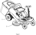
- the folding-type chassis of a lawn mower of embodiment 1 is shown in Figures 1-7 , which comprises a fixing disc 2 and at least one rotating disc 3 rotationally connected with the fixing disc 2.
- the fixing disc 2 is fixedly arranged at the bottom of the mower 1.
- each rotating disc 3 is respectively rotationally connected with the fixing disc 2
- two of the rotating discs 3 are respectively rotationally connected with the fixing disc 2
- the rest of the rotating discs 3 are respectively rotationally connected with the rotating discs 3 that are connected with the fixing disc 2.
- the plurality of the rotating discs 3 is connected in series.
- the mower 1 of the present invention can be a pushed-type mower or a riding-type mower.
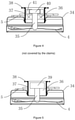
- the fixing disc 2 and the rotating disc 3 respectively comprise a shell 34.
- Mowing blades 4 are respectively arranged within the shells 34 of the fixing disc 2 and the rotating disc 3.
- the mowing blade 4 is transversely arranged in the shell 34, and a connecting shaft 35 is vertically arranged on the mowing blade 4.
- a bearing 36 interacting with the connecting shaft 35 is arranged on the shell 34.
- One end of the connecting shaft 35 is connected with the mowing blade 4, and the other end of the connecting shaft 35 extends into the bearing 36, thereby enabling the mowing blade 4 to be rotationally installed in the shell 34.
- a sleeve 37 is connected with the shell 34 of the fixing disc 2, and a connecting hole 38 is formed in the top end of the sleeve 37.
- the sleeve 37 is connected with a frame at the bottom of the mower 1 through the connecting hole 38.
- the fixing disc 2 is fixedly connected with the frame at the bottom of the mower 1 through the sleeve 37.
- a driving device used for driving the mowing blades 4 to rotate is arranged in the mower 1, and a grass-discharging hole is formed in the side surface or the top of the shell 34. When the mowing blades 4 are rotated, a wind pressure can be generated to blow the mowed grass out of the chassis.
- the driving device further comprises a plurality of driving motors 39, which are respectively arranged on the fixing disc 2 and the rotating disc 3.
- the driving motors 39 are respectively in transmission connection with the connecting shaft 35 of the mowing blade 4 in the fixing disc 2 and that in the rotating disc 3.
- the mowing blades 4 in the fixing disc 2 and the rotating disc 3 are driven by the driving motors 39 to rotate, thus conveniently mowing the lawn.
- the structure of the driving device can be various.
- the driving device comprises a driving motor 39, and the connecting shaft 35 of the mowing blade 4 in the fixing disc 2 and that in the rotating disc 3 penetrate through one end of the shells 34, and are respectively connected with a belt wheel 40.
- a belt is arranged between the belt wheel 40 on the fixing disc 2 and that on the rotating disc 3 in a sleeved mode.
- a through groove 41 allowing the belt to pass through is formed in the sleeve 37.
- the driving motor 39 is arranged either on the fixing disc 2 or on the frame at the bottom of the mower 1, and is rotationally connected with the belt wheel 40 on the fixing disc 2.
- a tensioning device is further arranged on the rotating arm 5.
- the tensioning device comprises a tensioning wheel and a spring.
- the tensioning wheel is rotationally connected with a connecting rod.
- a stop block is further arranged on the rotating arm 5, and the spring is located between the stop block and the connecting rod. In this way, the tensioning wheel is always abutted against the belt so that the belt is always kept in a tensioned state.
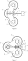
- Each rotating disc 3 is rotationally connected to the fixing disc 2 through a rotating arm 5, and the rotating arm 5 is connected to the center of the fixing disc 2.
- the rotating arm 5 is fixedly connected with the shell 34 of the rotating disc 3 through a bolt.
- the rotating arm 5 is sleeved outside the sleeve 37, and is rotationally connected with the sleeve 37.
- a sliding groove is formed in the rotating arm 5, and a bolt is arranged on the shell 34 of the fixing disc 2.
- the bolt penetrates through the shell 34 and the sliding groove, and is connected with a screw cap.
- the rotating arm 5 can rotate relative to the bolt.
- the sliding groove and the bolt Through the arrangement of the sliding groove and the bolt, a limiting function can be achieved when the rotating arm 5 is rotated, thus preventing the rotating arm 5 from excessively rotating or being separated from the sleeve 37.
- the number of the rotating discs 3 is two
- the number of the rotating arms 5 is also two.
- the two rotating arms 5 are arranged on the sleeve 37 in a stacked mode, and the two rotating arms are respectively provided with a sliding groove.
- two bolts are arranged on the shell 34 of the fixing disc 2.
- Gaskets 33 are respectively arranged between the shell 34 of the fixing disc 2 and the rotating arm 5, and between the screw cap and the rotating arm 5, thereby facilitating the rotation of the rotating arm 5.
- a lead-screw motor 7 is arranged on the mower 1, and an output end of the lead-screw motor 7 is connected with a lead screw 6 in a transmission mode.
- a lead screw seat matched with the lead screw 6 is arranged on the fixing disc 2, and a sliding block 8 is arranged on the lead screw 6.
- the sliding block 8 is connected with a rocking bar 9, and the rocking bar 9 is connected with the rotating arm 5.
- the lead-screw motor 7 can be a servo motor, a steering engine, or a motor capable of achieving the same function.
- the lead-screw motor 7 can be stopped at any time so that the sliding block 8 can be stopped at any position of the lead screw 6.
- the unfolding angle of the rotating disc 3 relative to the fixing disc 2 can be adjusted according to actual requirements.
- the rotating disc 3 is fixed relative to the fixing disc 2.
- the lead-screw motor 7 is initiated to rotate reversely, the rotating disc 3 is driven to fold and retract relative to the fixing disc 2. Namely, the rotational motion of the lead screw 6 is converted into the linear motion of the sliding block 8 by means of a ball screw 6.
- a plurality of rocking bars 9 is connected with the sliding block 8, and the plurality of rocking bars 9 is correspondingly connected with the plurality of rotating arms 5.
- the lead-screw motor 7 When the lead-screw motor 7 is initiated, the lead screw 6 is driven to rotate, enabling the sliding block 8 to move along the lead screw 6 towards the position where the fixing disc 2 is located.
- the plurality of rotating arms is driven to rotate simultaneously through the plurality of rocking bars 9, thereby enabling the rotating discs 3 to rotate around the fixing disc 2.
- the rotating discs 3 are unfolded relative to the fixing disc 2.
- the number of the lead-screw motors 7, the lead screws and the sliding blocks 8 can be greatly reduced.
- the rotating discs 3 can be respectively driven to unfold through a plurality of lead-screw motors 7, lead screws and sliding blocks 8.
- the rotating discs 3 when mowing a lawn with the mower 1, the rotating discs 3 can be rotated relative to the fixing disc 2, thereby enabling the rotating discs 3 and the fixing disc 2 to be transversely arranged side by side.
- the mowing area of mowing blades 4 in the rotating discs 3 and the fixing disc 2 can be greatly increased, and the mowing efficiency can be significantly improved.
- the rotating discs 3 can be rotated relative to the fixing disc 2 so that the rotating discs 3 and the fixing disc 2 are arranged side by side in a longitudinal direction. At this point, the rotating discs 3 can be partially or completely folded in the mower 1, thus reducing the space occupation of the mower 1 so that the storage and transportation can be facilitated.
Landscapes
- Life Sciences & Earth Sciences (AREA)
- Environmental Sciences (AREA)
- Harvester Elements (AREA)
Claims (5)
- Klappbares Gehäuse eines Rasenmähers, umfassend:eine Befestigungsscheibe (2), undmindestens eine Drehscheibe (3), die durch einen Dreharm (5) drehbar mit der Befestigungsscheibe (2) verbunden ist, wobei die Befestigungsscheibe (2) dafür ausgelegt ist, fest an der Unterseite des Mähers (1) angeordnet zu sein, wobei Mähmesser (4) jeweils in der Befestigungsscheibe (2) und der Drehscheibe (3) angeordnet sind, wobei eine Antriebsvorrichtung, die verwendet wird, um die Mähmesser (4) in Drehung zu versetzen, dafür ausgelegt ist, im Mäher (1) angeordnet zu sein,dadurch gekennzeichnet, dassein Spindelmotor (7) dafür ausgelegt ist, in dem Mäher (1) angeordnet zu sein, wobei eine Abtriebsseite des Spindelmotors (7) in Übertragungsverbindung mit einer Gewindespindel (6) steht, wobei auf der Gewindespindel ein Gleitstück (8) angeordnet ist, und das Gleitstück (8) mit einer schwenkbaren Stange (9) verbunden ist, wobei die schwenkbare Stange (9) mit dem Dreharm (5) verbunden ist.
- Klappbares Gehäuse eines Rasenmähers nach Anspruch 1, wobei die Anzahl der Drehscheiben (3) zwei beträgt und wobei die zwei Drehscheiben (3) jeweils drehbar mit der Befestigungsscheibe (2) verbunden sind.
- Klappbares Gehäuse eines Rasenmähers nach Anspruch 1, wobei, wenn die Anzahl der Drehscheiben (3) mehr als zwei beträgt, zwei der Drehscheiben (3) jeweils mit der Befestigungsscheibe (2) drehbar verbunden sind und die übrigen Drehscheiben (3) jeweils mit den Drehscheiben (3) drehbar verbunden sind, die mit der Befestigungsscheibe (2) verbunden sind.
- Klappbares Gehäuse eines Rasenmähers nach Anspruch 1-3, wobei die Antriebsvorrichtung mehrere Antriebsmotoren (39) umfasst, die jeweils auf der Befestigungsscheibe (2) und der Drehscheibe (3) angeordnet sind, wobei die Antriebsmotoren (39) jeweils in Übertragungsverbindung mit den Mähmessern (4) in der Befestigungsscheibe (2) und der Drehscheibe (3) stehen.
- Klappbares Gehäuse eines Rasenmähers nach Anspruch 1-3, wobei die Antriebsvorrichtung einen Antriebsmotor (39) umfasst, und die Mähmesser (4) in der Befestigungsscheibe (2) und der Drehscheibe (3) jeweils mit einem Riemenrad (40) verbunden sind, wobei ein Riemen zwischen dem Riemenrad (40) auf der Befestigungsscheibe (2) und dem auf der Drehscheibe (3) in einer Hülsenform angeordnet ist, wobei der Antriebsmotor (39) in Übertragungsverbindung mit dem Riemenrad (40) auf der Befestigungsscheibe (2) steht.
Applications Claiming Priority (2)
| Application Number | Priority Date | Filing Date | Title |
|---|---|---|---|
| CN201811486847.XA CN109526402B (zh) | 2018-12-06 | 2018-12-06 | 一种割草机折叠式底盘 |
| PCT/CN2019/071545 WO2020113777A1 (zh) | 2018-12-06 | 2019-01-14 | 一种割草机折叠式底盘 |
Publications (3)
| Publication Number | Publication Date |
|---|---|
| EP3689128A4 EP3689128A4 (de) | 2020-08-05 |
| EP3689128A1 EP3689128A1 (de) | 2020-08-05 |
| EP3689128B1 true EP3689128B1 (de) | 2022-03-16 |
Family
ID=65854173
Family Applications (1)
| Application Number | Title | Priority Date | Filing Date |
|---|---|---|---|
| EP19717746.2A Active EP3689128B1 (de) | 2018-12-06 | 2019-01-14 | Klapprahmen eines rasenmähers |
Country Status (4)
| Country | Link |
|---|---|
| US (1) | US20210400877A1 (de) |
| EP (1) | EP3689128B1 (de) |
| CN (3) | CN118216312A (de) |
| WO (1) | WO2020113777A1 (de) |
Cited By (1)
| Publication number | Priority date | Publication date | Assignee | Title |
|---|---|---|---|---|
| WO2026062548A1 (en) * | 2024-09-19 | 2026-03-26 | Free Green Nature S.r.l. | Grass-cutting equipment |
Families Citing this family (4)
| Publication number | Priority date | Publication date | Assignee | Title |
|---|---|---|---|---|
| IT201800009580A1 (it) * | 2018-10-18 | 2020-04-18 | Mdb Srl Con Socio Unico | Tagliaerba radiocomandato |
| JP7157001B2 (ja) | 2019-05-17 | 2022-10-19 | 株式会社クボタ | 草刈機 |
| US11785886B1 (en) * | 2020-09-01 | 2023-10-17 | Bad Boy Mowers, Llc | Zero-turn-radius riding mower front wheel positioning system |
| CN119422611A (zh) * | 2024-11-12 | 2025-02-14 | 湖州职业技术学院 | 一种智能除草机 |
Family Cites Families (26)
| Publication number | Priority date | Publication date | Assignee | Title |
|---|---|---|---|---|
| GB190038A (en) * | 1922-01-14 | 1922-12-14 | Charles Frederick Webb | Improvements in foot operated pumps |
| GB564881A (en) * | 1943-07-28 | 1944-10-17 | Worcester Windshields & Caseme | Improvements relating to angularly-movable panels, such as vehicle windscreens |
| DE2115101A1 (de) * | 1971-03-29 | 1972-10-05 | Haseloff, Fritz, 3500 Kassel | Rasenmäher |
| US4024695A (en) * | 1974-03-08 | 1977-05-24 | Fritz Haseloff | Lawn mower |
| NL7905005A (nl) * | 1979-06-27 | 1980-12-30 | Vogelenzang Alexander J | Cirkelmaaier met variabele werkbreedte. |
| DE4407812A1 (de) * | 1994-03-09 | 1995-09-14 | Popiolek Franz M | Trommelmähmaschine |
| JPH07267358A (ja) * | 1994-03-31 | 1995-10-17 | Bando Chem Ind Ltd | 環状物の着脱装置 |
| JP3308949B2 (ja) * | 1999-11-10 | 2002-07-29 | タキゲン製造株式会社 | ファスナーロック装置 |
| US6702200B2 (en) * | 2001-07-24 | 2004-03-09 | The Board Of Regents For Oklahoma State University | Nozzle attitude controller for spot and variable rate application of agricultural chemicals and fertilizers |
| JP4324964B2 (ja) * | 2004-01-14 | 2009-09-02 | 株式会社アテックス | 自走式乗用草刈機 |
| FR2871077B1 (fr) * | 2004-06-02 | 2007-10-05 | Gyrax Soc Par Actions Simplifi | Broyeur a modules de broyage articules |
| JP5454865B2 (ja) * | 2009-03-31 | 2014-03-26 | 日立工機株式会社 | 芝刈機 |
| WO2010140929A1 (en) * | 2009-06-01 | 2010-12-09 | Andersson, Jonas | Lawn mower |
| WO2010140932A1 (en) * | 2009-06-02 | 2010-12-09 | Husqvarna Ab | Telescoping of cutting deck |
| DE102011080385B3 (de) * | 2011-06-10 | 2012-12-06 | Wiedenmann Gmbh | Mähdeck |
| KR101471037B1 (ko) * | 2013-04-11 | 2014-12-09 | 모영환 | 땅속 작물 수확기 |
| JP6542003B2 (ja) * | 2015-03-30 | 2019-07-10 | 中国電力株式会社 | 自走式作業用ロボット |
| CN106664964A (zh) * | 2017-03-02 | 2017-05-17 | 农业部南京农业机械化研究所 | 一种弹齿式棉花采摘装置 |
| CN207465216U (zh) * | 2017-09-14 | 2018-06-08 | 邵东智能制造技术研究院有限公司 | 一种简易轻便的机械手 |
| CN207252233U (zh) * | 2017-09-19 | 2018-04-20 | 浙江三锋实业股份有限公司 | 一种用于割草机的扶手高度调节机构 |
| CN108029325A (zh) * | 2017-12-31 | 2018-05-15 | 薛凤梧 | 割草覆盖还田机 |
| CN108124584A (zh) * | 2018-02-08 | 2018-06-08 | 北京时代沃林科技发展有限公司 | 一种新型避让式割草机 |
| CN108312141A (zh) * | 2018-04-13 | 2018-07-24 | 东北大学 | 一种送餐机器人的摆盘机械臂及使用方法 |
| CN209435831U (zh) * | 2018-12-06 | 2019-09-27 | 宁波朗辉工具有限公司 | 一种割草机折叠式底盘 |
| CN209914513U (zh) * | 2018-12-29 | 2020-01-10 | 宁波朗辉工具有限公司 | 一种割草机折叠式底盘结构 |
| CN113228926B (zh) * | 2021-05-27 | 2022-06-10 | 杭州生达轴承有限公司 | 一种自动避障割草设备 |
-
2018
- 2018-12-06 CN CN202410636582.6A patent/CN118216312A/zh active Pending
- 2018-12-06 CN CN201811486847.XA patent/CN109526402B/zh active Active
- 2018-12-06 CN CN202410636564.8A patent/CN118252028A/zh active Pending
-
2019
- 2019-01-14 WO PCT/CN2019/071545 patent/WO2020113777A1/zh not_active Ceased
- 2019-01-14 EP EP19717746.2A patent/EP3689128B1/de active Active
- 2019-01-14 US US16/325,643 patent/US20210400877A1/en not_active Abandoned
Cited By (1)
| Publication number | Priority date | Publication date | Assignee | Title |
|---|---|---|---|---|
| WO2026062548A1 (en) * | 2024-09-19 | 2026-03-26 | Free Green Nature S.r.l. | Grass-cutting equipment |
Also Published As
| Publication number | Publication date |
|---|---|
| CN109526402A (zh) | 2019-03-29 |
| CN118252028A (zh) | 2024-06-28 |
| US20210400877A1 (en) | 2021-12-30 |
| CN109526402B (zh) | 2024-06-07 |
| EP3689128A4 (de) | 2020-08-05 |
| CN118216312A (zh) | 2024-06-21 |
| EP3689128A1 (de) | 2020-08-05 |
| WO2020113777A1 (zh) | 2020-06-11 |
Similar Documents
| Publication | Publication Date | Title |
|---|---|---|
| EP3689128B1 (de) | Klapprahmen eines rasenmähers | |
| US4998948A (en) | Lawn mower | |
| US4487006A (en) | Lawn mower | |
| CA2739632C (en) | Swather tractor with frame suspension | |
| CN210470303U (zh) | 一种软轴传动全地形遥控割草机 | |
| CN110381725A (zh) | 包括以负外倾角设置的轮的自推进式机器人割草机 | |
| US20020053194A1 (en) | Rotary cutting unit for mower | |
| CN211793024U (zh) | 一种坐骑式割草机 | |
| US6449933B1 (en) | Lawn mower | |
| CN112889454A (zh) | 一种具有高度调节功能的可折叠大型割草设备 | |
| US9167741B2 (en) | Lawn care vehicle with rear wheel axle assembly | |
| US10980176B1 (en) | Minimal radius system for cutting vegetation | |
| AU2012372909A1 (en) | Cutting deck lift system for lawn mower | |
| JP6062313B2 (ja) | 多連モア | |
| CN2760928Y (zh) | 手推式割草机 | |
| CN209914513U (zh) | 一种割草机折叠式底盘结构 | |
| JP2948983B2 (ja) | 芝刈機 | |
| US20060090441A1 (en) | Lawn mower/lawn edger for use with an electric scooter | |
| JP3435134B2 (ja) | 草刈り機 | |
| JPS606181Y2 (ja) | モアの前ゲ−ジ輪支持装置 | |
| CN223067530U (zh) | 阔叶牧草收割机 | |
| US12616090B2 (en) | Suspension system for electric power equipment | |
| CN222396213U (zh) | 一种割草机刀头高度调节装置 | |
| CN216087718U (zh) | 一种大型平面割草机的尾轮连杆机构 | |
| CN215269592U (zh) | 一种市政管理用道路绿植修剪装置 |
Legal Events
| Date | Code | Title | Description |
|---|---|---|---|
| STAA | Information on the status of an ep patent application or granted ep patent |
Free format text: STATUS: UNKNOWN |
|
| STAA | Information on the status of an ep patent application or granted ep patent |
Free format text: STATUS: THE INTERNATIONAL PUBLICATION HAS BEEN MADE |
|
| PUAI | Public reference made under article 153(3) epc to a published international application that has entered the european phase |
Free format text: ORIGINAL CODE: 0009012 |
|
| STAA | Information on the status of an ep patent application or granted ep patent |
Free format text: STATUS: REQUEST FOR EXAMINATION WAS MADE |
|
| 17P | Request for examination filed |
Effective date: 20190426 |
|
| A4 | Supplementary search report drawn up and despatched |
Effective date: 20200317 |
|
| AK | Designated contracting states |
Kind code of ref document: A1 Designated state(s): AL AT BE BG CH CY CZ DE DK EE ES FI FR GB GR HR HU IE IS IT LI LT LU LV MC MK MT NL NO PL PT RO RS SE SI SK SM TR |
|
| AX | Request for extension of the european patent |
Extension state: BA ME |
|
| STAA | Information on the status of an ep patent application or granted ep patent |
Free format text: STATUS: EXAMINATION IS IN PROGRESS |
|
| 17Q | First examination report despatched |
Effective date: 20201218 |
|
| GRAP | Despatch of communication of intention to grant a patent |
Free format text: ORIGINAL CODE: EPIDOSNIGR1 |
|
| STAA | Information on the status of an ep patent application or granted ep patent |
Free format text: STATUS: GRANT OF PATENT IS INTENDED |
|
| DAV | Request for validation of the european patent (deleted) | ||
| DAX | Request for extension of the european patent (deleted) | ||
| INTG | Intention to grant announced |
Effective date: 20210714 |
|
| GRAS | Grant fee paid |
Free format text: ORIGINAL CODE: EPIDOSNIGR3 |
|
| GRAA | (expected) grant |
Free format text: ORIGINAL CODE: 0009210 |
|
| STAA | Information on the status of an ep patent application or granted ep patent |
Free format text: STATUS: THE PATENT HAS BEEN GRANTED |
|
| AK | Designated contracting states |
Kind code of ref document: B1 Designated state(s): AL AT BE BG CH CY CZ DE DK EE ES FI FR GB GR HR HU IE IS IT LI LT LU LV MC MK MT NL NO PL PT RO RS SE SI SK SM TR |
|
| REG | Reference to a national code |
Ref country code: GB Ref legal event code: FG4D |
|
| RIN1 | Information on inventor provided before grant (corrected) |
Inventor name: ZHAO, YANHUI |
|
| REG | Reference to a national code |
Ref country code: CH Ref legal event code: EP Ref country code: DE Ref legal event code: R096 Ref document number: 602019012620 Country of ref document: DE |
|
| REG | Reference to a national code |
Ref country code: IE Ref legal event code: FG4D |
|
| REG | Reference to a national code |
Ref country code: AT Ref legal event code: REF Ref document number: 1475240 Country of ref document: AT Kind code of ref document: T Effective date: 20220415 |
|
| REG | Reference to a national code |
Ref country code: LT Ref legal event code: MG9D |
|
| REG | Reference to a national code |
Ref country code: NL Ref legal event code: MP Effective date: 20220316 |
|
| PG25 | Lapsed in a contracting state [announced via postgrant information from national office to epo] |
Ref country code: SE Free format text: LAPSE BECAUSE OF FAILURE TO SUBMIT A TRANSLATION OF THE DESCRIPTION OR TO PAY THE FEE WITHIN THE PRESCRIBED TIME-LIMIT Effective date: 20220316 Ref country code: RS Free format text: LAPSE BECAUSE OF FAILURE TO SUBMIT A TRANSLATION OF THE DESCRIPTION OR TO PAY THE FEE WITHIN THE PRESCRIBED TIME-LIMIT Effective date: 20220316 Ref country code: NO Free format text: LAPSE BECAUSE OF FAILURE TO SUBMIT A TRANSLATION OF THE DESCRIPTION OR TO PAY THE FEE WITHIN THE PRESCRIBED TIME-LIMIT Effective date: 20220616 Ref country code: LT Free format text: LAPSE BECAUSE OF FAILURE TO SUBMIT A TRANSLATION OF THE DESCRIPTION OR TO PAY THE FEE WITHIN THE PRESCRIBED TIME-LIMIT Effective date: 20220316 Ref country code: HR Free format text: LAPSE BECAUSE OF FAILURE TO SUBMIT A TRANSLATION OF THE DESCRIPTION OR TO PAY THE FEE WITHIN THE PRESCRIBED TIME-LIMIT Effective date: 20220316 Ref country code: BG Free format text: LAPSE BECAUSE OF FAILURE TO SUBMIT A TRANSLATION OF THE DESCRIPTION OR TO PAY THE FEE WITHIN THE PRESCRIBED TIME-LIMIT Effective date: 20220616 |
|
| REG | Reference to a national code |
Ref country code: AT Ref legal event code: MK05 Ref document number: 1475240 Country of ref document: AT Kind code of ref document: T Effective date: 20220316 |
|
| PG25 | Lapsed in a contracting state [announced via postgrant information from national office to epo] |
Ref country code: LV Free format text: LAPSE BECAUSE OF FAILURE TO SUBMIT A TRANSLATION OF THE DESCRIPTION OR TO PAY THE FEE WITHIN THE PRESCRIBED TIME-LIMIT Effective date: 20220316 Ref country code: GR Free format text: LAPSE BECAUSE OF FAILURE TO SUBMIT A TRANSLATION OF THE DESCRIPTION OR TO PAY THE FEE WITHIN THE PRESCRIBED TIME-LIMIT Effective date: 20220617 Ref country code: FI Free format text: LAPSE BECAUSE OF FAILURE TO SUBMIT A TRANSLATION OF THE DESCRIPTION OR TO PAY THE FEE WITHIN THE PRESCRIBED TIME-LIMIT Effective date: 20220316 |
|
| PG25 | Lapsed in a contracting state [announced via postgrant information from national office to epo] |
Ref country code: NL Free format text: LAPSE BECAUSE OF FAILURE TO SUBMIT A TRANSLATION OF THE DESCRIPTION OR TO PAY THE FEE WITHIN THE PRESCRIBED TIME-LIMIT Effective date: 20220316 |
|
| PG25 | Lapsed in a contracting state [announced via postgrant information from national office to epo] |
Ref country code: SM Free format text: LAPSE BECAUSE OF FAILURE TO SUBMIT A TRANSLATION OF THE DESCRIPTION OR TO PAY THE FEE WITHIN THE PRESCRIBED TIME-LIMIT Effective date: 20220316 Ref country code: SK Free format text: LAPSE BECAUSE OF FAILURE TO SUBMIT A TRANSLATION OF THE DESCRIPTION OR TO PAY THE FEE WITHIN THE PRESCRIBED TIME-LIMIT Effective date: 20220316 Ref country code: RO Free format text: LAPSE BECAUSE OF FAILURE TO SUBMIT A TRANSLATION OF THE DESCRIPTION OR TO PAY THE FEE WITHIN THE PRESCRIBED TIME-LIMIT Effective date: 20220316 Ref country code: PT Free format text: LAPSE BECAUSE OF FAILURE TO SUBMIT A TRANSLATION OF THE DESCRIPTION OR TO PAY THE FEE WITHIN THE PRESCRIBED TIME-LIMIT Effective date: 20220718 Ref country code: ES Free format text: LAPSE BECAUSE OF FAILURE TO SUBMIT A TRANSLATION OF THE DESCRIPTION OR TO PAY THE FEE WITHIN THE PRESCRIBED TIME-LIMIT Effective date: 20220316 Ref country code: EE Free format text: LAPSE BECAUSE OF FAILURE TO SUBMIT A TRANSLATION OF THE DESCRIPTION OR TO PAY THE FEE WITHIN THE PRESCRIBED TIME-LIMIT Effective date: 20220316 Ref country code: CZ Free format text: LAPSE BECAUSE OF FAILURE TO SUBMIT A TRANSLATION OF THE DESCRIPTION OR TO PAY THE FEE WITHIN THE PRESCRIBED TIME-LIMIT Effective date: 20220316 Ref country code: AT Free format text: LAPSE BECAUSE OF FAILURE TO SUBMIT A TRANSLATION OF THE DESCRIPTION OR TO PAY THE FEE WITHIN THE PRESCRIBED TIME-LIMIT Effective date: 20220316 |
|
| PG25 | Lapsed in a contracting state [announced via postgrant information from national office to epo] |
Ref country code: PL Free format text: LAPSE BECAUSE OF FAILURE TO SUBMIT A TRANSLATION OF THE DESCRIPTION OR TO PAY THE FEE WITHIN THE PRESCRIBED TIME-LIMIT Effective date: 20220316 Ref country code: IS Free format text: LAPSE BECAUSE OF FAILURE TO SUBMIT A TRANSLATION OF THE DESCRIPTION OR TO PAY THE FEE WITHIN THE PRESCRIBED TIME-LIMIT Effective date: 20220716 Ref country code: AL Free format text: LAPSE BECAUSE OF FAILURE TO SUBMIT A TRANSLATION OF THE DESCRIPTION OR TO PAY THE FEE WITHIN THE PRESCRIBED TIME-LIMIT Effective date: 20220316 |
|
| REG | Reference to a national code |
Ref country code: DE Ref legal event code: R097 Ref document number: 602019012620 Country of ref document: DE |
|
| PLBE | No opposition filed within time limit |
Free format text: ORIGINAL CODE: 0009261 |
|
| STAA | Information on the status of an ep patent application or granted ep patent |
Free format text: STATUS: NO OPPOSITION FILED WITHIN TIME LIMIT |
|
| PG25 | Lapsed in a contracting state [announced via postgrant information from national office to epo] |
Ref country code: DK Free format text: LAPSE BECAUSE OF FAILURE TO SUBMIT A TRANSLATION OF THE DESCRIPTION OR TO PAY THE FEE WITHIN THE PRESCRIBED TIME-LIMIT Effective date: 20220316 |
|
| 26N | No opposition filed |
Effective date: 20221219 |
|
| PG25 | Lapsed in a contracting state [announced via postgrant information from national office to epo] |
Ref country code: SI Free format text: LAPSE BECAUSE OF FAILURE TO SUBMIT A TRANSLATION OF THE DESCRIPTION OR TO PAY THE FEE WITHIN THE PRESCRIBED TIME-LIMIT Effective date: 20220316 |
|
| PGFP | Annual fee paid to national office [announced via postgrant information from national office to epo] |
Ref country code: FR Payment date: 20230123 Year of fee payment: 5 |
|
| PGFP | Annual fee paid to national office [announced via postgrant information from national office to epo] |
Ref country code: DE Payment date: 20221202 Year of fee payment: 5 |
|
| PG25 | Lapsed in a contracting state [announced via postgrant information from national office to epo] |
Ref country code: IT Free format text: LAPSE BECAUSE OF FAILURE TO SUBMIT A TRANSLATION OF THE DESCRIPTION OR TO PAY THE FEE WITHIN THE PRESCRIBED TIME-LIMIT Effective date: 20220316 |
|
| REG | Reference to a national code |
Ref country code: CH Ref legal event code: PL |
|
| GBPC | Gb: european patent ceased through non-payment of renewal fee |
Effective date: 20230114 |
|
| PG25 | Lapsed in a contracting state [announced via postgrant information from national office to epo] |
Ref country code: LU Free format text: LAPSE BECAUSE OF NON-PAYMENT OF DUE FEES Effective date: 20230114 |
|
| REG | Reference to a national code |
Ref country code: BE Ref legal event code: MM Effective date: 20230131 |
|
| REG | Reference to a national code |
Ref country code: DE Ref legal event code: R082 Ref document number: 602019012620 Country of ref document: DE Representative=s name: SUN, YIMING, M.SC. DIPL. SC. POL. UNIV., DE |
|
| PG25 | Lapsed in a contracting state [announced via postgrant information from national office to epo] |
Ref country code: LI Free format text: LAPSE BECAUSE OF NON-PAYMENT OF DUE FEES Effective date: 20230131 Ref country code: GB Free format text: LAPSE BECAUSE OF NON-PAYMENT OF DUE FEES Effective date: 20230114 Ref country code: CH Free format text: LAPSE BECAUSE OF NON-PAYMENT OF DUE FEES Effective date: 20230131 |
|
| PG25 | Lapsed in a contracting state [announced via postgrant information from national office to epo] |
Ref country code: BE Free format text: LAPSE BECAUSE OF NON-PAYMENT OF DUE FEES Effective date: 20230131 |
|
| PG25 | Lapsed in a contracting state [announced via postgrant information from national office to epo] |
Ref country code: IE Free format text: LAPSE BECAUSE OF NON-PAYMENT OF DUE FEES Effective date: 20230114 |
|
| PG25 | Lapsed in a contracting state [announced via postgrant information from national office to epo] |
Ref country code: MC Free format text: LAPSE BECAUSE OF FAILURE TO SUBMIT A TRANSLATION OF THE DESCRIPTION OR TO PAY THE FEE WITHIN THE PRESCRIBED TIME-LIMIT Effective date: 20220316 |
|
| PG25 | Lapsed in a contracting state [announced via postgrant information from national office to epo] |
Ref country code: MC Free format text: LAPSE BECAUSE OF FAILURE TO SUBMIT A TRANSLATION OF THE DESCRIPTION OR TO PAY THE FEE WITHIN THE PRESCRIBED TIME-LIMIT Effective date: 20220316 |
|
| REG | Reference to a national code |
Ref country code: DE Ref legal event code: R119 Ref document number: 602019012620 Country of ref document: DE |
|
| PG25 | Lapsed in a contracting state [announced via postgrant information from national office to epo] |
Ref country code: DE Free format text: LAPSE BECAUSE OF NON-PAYMENT OF DUE FEES Effective date: 20240801 |
|
| PG25 | Lapsed in a contracting state [announced via postgrant information from national office to epo] |
Ref country code: FR Free format text: LAPSE BECAUSE OF NON-PAYMENT OF DUE FEES Effective date: 20240131 |
|
| PG25 | Lapsed in a contracting state [announced via postgrant information from national office to epo] |
Ref country code: FR Free format text: LAPSE BECAUSE OF NON-PAYMENT OF DUE FEES Effective date: 20240131 Ref country code: DE Free format text: LAPSE BECAUSE OF NON-PAYMENT OF DUE FEES Effective date: 20240801 |
|
| PG25 | Lapsed in a contracting state [announced via postgrant information from national office to epo] |
Ref country code: CY Free format text: LAPSE BECAUSE OF FAILURE TO SUBMIT A TRANSLATION OF THE DESCRIPTION OR TO PAY THE FEE WITHIN THE PRESCRIBED TIME-LIMIT; INVALID AB INITIO Effective date: 20190114 |
|
| PG25 | Lapsed in a contracting state [announced via postgrant information from national office to epo] |
Ref country code: HU Free format text: LAPSE BECAUSE OF FAILURE TO SUBMIT A TRANSLATION OF THE DESCRIPTION OR TO PAY THE FEE WITHIN THE PRESCRIBED TIME-LIMIT; INVALID AB INITIO Effective date: 20190114 |
|
| PG25 | Lapsed in a contracting state [announced via postgrant information from national office to epo] |
Ref country code: TR Free format text: LAPSE BECAUSE OF FAILURE TO SUBMIT A TRANSLATION OF THE DESCRIPTION OR TO PAY THE FEE WITHIN THE PRESCRIBED TIME-LIMIT Effective date: 20220316 |