EP3689471A1 - Filtre d'extrémité de soupape interne - Google Patents
Filtre d'extrémité de soupape interne Download PDFInfo
- Publication number
- EP3689471A1 EP3689471A1 EP20166368.9A EP20166368A EP3689471A1 EP 3689471 A1 EP3689471 A1 EP 3689471A1 EP 20166368 A EP20166368 A EP 20166368A EP 3689471 A1 EP3689471 A1 EP 3689471A1
- Authority
- EP
- European Patent Office
- Prior art keywords
- fluid
- valve
- filter
- valve stem
- tip
- Prior art date
- Legal status (The legal status is an assumption and is not a legal conclusion. Google has not performed a legal analysis and makes no representation as to the accuracy of the status listed.)
- Granted
Links
Images




Classifications
-
- B—PERFORMING OPERATIONS; TRANSPORTING
- B05—SPRAYING OR ATOMISING IN GENERAL; APPLYING FLUENT MATERIALS TO SURFACES, IN GENERAL
- B05B—SPRAYING APPARATUS; ATOMISING APPARATUS; NOZZLES
- B05B1/00—Nozzles, spray heads or other outlets, with or without auxiliary devices such as valves, heating means
- B05B1/30—Nozzles, spray heads or other outlets, with or without auxiliary devices such as valves, heating means designed to control volume of flow, e.g. with adjustable passages
- B05B1/3033—Nozzles, spray heads or other outlets, with or without auxiliary devices such as valves, heating means designed to control volume of flow, e.g. with adjustable passages the control being effected by relative coaxial longitudinal movement of the controlling element and the spray head
- B05B1/304—Nozzles, spray heads or other outlets, with or without auxiliary devices such as valves, heating means designed to control volume of flow, e.g. with adjustable passages the control being effected by relative coaxial longitudinal movement of the controlling element and the spray head the controlling element being a lift valve
- B05B1/3046—Nozzles, spray heads or other outlets, with or without auxiliary devices such as valves, heating means designed to control volume of flow, e.g. with adjustable passages the control being effected by relative coaxial longitudinal movement of the controlling element and the spray head the controlling element being a lift valve the valve element, e.g. a needle, co-operating with a valve seat located downstream of the valve element and its actuating means, generally in the proximity of the outlet orifice
- B05B1/306—Nozzles, spray heads or other outlets, with or without auxiliary devices such as valves, heating means designed to control volume of flow, e.g. with adjustable passages the control being effected by relative coaxial longitudinal movement of the controlling element and the spray head the controlling element being a lift valve the valve element, e.g. a needle, co-operating with a valve seat located downstream of the valve element and its actuating means, generally in the proximity of the outlet orifice the actuating means being a fluid
-
- B—PERFORMING OPERATIONS; TRANSPORTING
- B05—SPRAYING OR ATOMISING IN GENERAL; APPLYING FLUENT MATERIALS TO SURFACES, IN GENERAL
- B05B—SPRAYING APPARATUS; ATOMISING APPARATUS; NOZZLES
- B05B1/00—Nozzles, spray heads or other outlets, with or without auxiliary devices such as valves, heating means
- B05B1/14—Nozzles, spray heads or other outlets, with or without auxiliary devices such as valves, heating means with multiple outlet openings; with strainers in or outside the outlet opening
-
- B—PERFORMING OPERATIONS; TRANSPORTING
- B05—SPRAYING OR ATOMISING IN GENERAL; APPLYING FLUENT MATERIALS TO SURFACES, IN GENERAL
- B05B—SPRAYING APPARATUS; ATOMISING APPARATUS; NOZZLES
- B05B15/00—Details of spraying plant or spraying apparatus not otherwise provided for; Accessories
- B05B15/40—Filters located upstream of the spraying outlets
-
- B—PERFORMING OPERATIONS; TRANSPORTING
- B05—SPRAYING OR ATOMISING IN GENERAL; APPLYING FLUENT MATERIALS TO SURFACES, IN GENERAL
- B05C—APPARATUS FOR APPLYING FLUENT MATERIALS TO SURFACES, IN GENERAL
- B05C11/00—Component parts, details or accessories not specifically provided for in groups B05C1/00 - B05C9/00
- B05C11/10—Storage, supply or control of liquid or other fluent material; Recovery of excess liquid or other fluent material
- B05C11/1047—Apparatus or installations for supplying liquid or other fluent material comprising a buffer container or an accumulator between the supply source and the applicator
-
- B—PERFORMING OPERATIONS; TRANSPORTING
- B05—SPRAYING OR ATOMISING IN GENERAL; APPLYING FLUENT MATERIALS TO SURFACES, IN GENERAL
- B05C—APPARATUS FOR APPLYING FLUENT MATERIALS TO SURFACES, IN GENERAL
- B05C5/00—Apparatus in which liquid or other fluent material is projected, poured or allowed to flow on to the surface of the work
- B05C5/02—Apparatus in which liquid or other fluent material is projected, poured or allowed to flow on to the surface of the work the liquid or other fluent material being discharged through an outlet orifice by pressure, e.g. from an outlet device in contact or almost in contact, with the work
- B05C5/0225—Apparatus in which liquid or other fluent material is projected, poured or allowed to flow on to the surface of the work the liquid or other fluent material being discharged through an outlet orifice by pressure, e.g. from an outlet device in contact or almost in contact, with the work characterised by flow controlling means, e.g. valves, located proximate the outlet
-
- B—PERFORMING OPERATIONS; TRANSPORTING
- B05—SPRAYING OR ATOMISING IN GENERAL; APPLYING FLUENT MATERIALS TO SURFACES, IN GENERAL
- B05C—APPARATUS FOR APPLYING FLUENT MATERIALS TO SURFACES, IN GENERAL
- B05C5/00—Apparatus in which liquid or other fluent material is projected, poured or allowed to flow on to the surface of the work
- B05C5/02—Apparatus in which liquid or other fluent material is projected, poured or allowed to flow on to the surface of the work the liquid or other fluent material being discharged through an outlet orifice by pressure, e.g. from an outlet device in contact or almost in contact, with the work
- B05C5/027—Coating heads with several outlets, e.g. aligned transversally to the moving direction of a web to be coated
- B05C5/0275—Coating heads with several outlets, e.g. aligned transversally to the moving direction of a web to be coated flow controlled, e.g. by a valve
- B05C5/0279—Coating heads with several outlets, e.g. aligned transversally to the moving direction of a web to be coated flow controlled, e.g. by a valve independently, e.g. individually, flow controlled
-
- B—PERFORMING OPERATIONS; TRANSPORTING
- B01—PHYSICAL OR CHEMICAL PROCESSES OR APPARATUS IN GENERAL
- B01D—SEPARATION
- B01D2201/00—Details relating to filtering apparatus
- B01D2201/02—Filtering elements having a conical form
-
- B—PERFORMING OPERATIONS; TRANSPORTING
- B05—SPRAYING OR ATOMISING IN GENERAL; APPLYING FLUENT MATERIALS TO SURFACES, IN GENERAL
- B05C—APPARATUS FOR APPLYING FLUENT MATERIALS TO SURFACES, IN GENERAL
- B05C11/00—Component parts, details or accessories not specifically provided for in groups B05C1/00 - B05C9/00
- B05C11/10—Storage, supply or control of liquid or other fluent material; Recovery of excess liquid or other fluent material
- B05C11/1042—Storage, supply or control of liquid or other fluent material; Recovery of excess liquid or other fluent material provided with means for heating or cooling the liquid or other fluent material in the supplying means upstream of the applying apparatus
-
- B—PERFORMING OPERATIONS; TRANSPORTING
- B05—SPRAYING OR ATOMISING IN GENERAL; APPLYING FLUENT MATERIALS TO SURFACES, IN GENERAL
- B05C—APPARATUS FOR APPLYING FLUENT MATERIALS TO SURFACES, IN GENERAL
- B05C5/00—Apparatus in which liquid or other fluent material is projected, poured or allowed to flow on to the surface of the work
- B05C5/02—Apparatus in which liquid or other fluent material is projected, poured or allowed to flow on to the surface of the work the liquid or other fluent material being discharged through an outlet orifice by pressure, e.g. from an outlet device in contact or almost in contact, with the work
- B05C5/0225—Apparatus in which liquid or other fluent material is projected, poured or allowed to flow on to the surface of the work the liquid or other fluent material being discharged through an outlet orifice by pressure, e.g. from an outlet device in contact or almost in contact, with the work characterised by flow controlling means, e.g. valves, located proximate the outlet
- B05C5/0237—Fluid actuated valves
Definitions
- the present disclosure relates generally to systems for dispensing hot melt adhesive. More particularly, the present disclosure relates to filters for dispense modules having valves from which melted hot melt adhesive is applied.
- Hot melt dispensing systems are typically used in manufacturing assembly lines to automatically disperse an adhesive used in the construction of packaging materials such as boxes, cartons and the like.
- Hot melt dispensing systems conventionally comprise a material tank, heating elements, a pump and a dispenser. Solid polymer pellets are melted in the tank using a heating element before being supplied to the dispenser by the pump. Because the melted pellets will re-solidify into solid form if permitted to cool, the melted pellets must be maintained at temperature from the tank to the dispenser. This typically requires placement of heating elements in the tank, the pump and the dispenser, as well as heating any tubing or hoses that connect those components.
- conventional hot melt dispensing systems typically utilize tanks having large volumes so that extended periods of dispensing can occur after the pellets contained therein are melted.
- the large volume of pellets within the tank requires a lengthy period of time to completely melt, which increases start-up times for the system.
- a typical tank includes a plurality of heating elements lining the walls of a rectangular, gravity-fed tank such that melted pellets along the walls prevents the heating elements from efficiently melting pellets in the center of the container.
- the extended time required to melt the pellets in these tanks increases the likelihood of "charring” or darkening of the adhesive due to prolonged heat exposure.
- a fluid dispensing valve comprises a dispensing module, a discharge orifice, a valve stem and a filter.
- the module has a fluid inlet, a fluid outlet and a fluid passage connecting the fluid inlet and the fluid outlet.
- the discharge orifice is in fluid communication with the fluid outlet.
- the valve stem extends into the fluid passage to close-off the discharger orifice.
- the filter is disposed within the fluid passage and surrounds the valve stem.
- FIG. 1 is a schematic view of system 10, which is a system for dispensing hot melt adhesive.
- System 10 includes cold section 12, hot section 14, air source 16, air control valve 17, and controller 18.
- cold section 12 includes container 20 and feed assembly 22, which includes vacuum assembly 24, feed hose 26, and inlet 28.
- hot section 14 includes melt system 30, pump 32, and dispenser 34.
- Air source 16 is a source of compressed air supplied to components of system 10 in both cold section 12 and hot section 14.
- Air control valve 17 is connected to air source 16 via air hose 35A, and selectively controls air flow from air source 16 through air hose 35B to vacuum assembly 24 and through air hose 35C to motor 36 of pump 32.
- Air hose 35D connects air source 16 to dispenser 34, bypassing air control valve 17.
- Controller 18 is connected in communication with various components of system 10, such as air control valve 17, melt system 30, pump 32, and/or dispenser 34, for controlling operation of system 10.
- Container 20 can be a hopper for containing a quantity of solid adhesive pellets for use by system 10. Suitable adhesives can include, for example, a thermoplastic polymer glue such as ethylene vinyl acetate (EVA) or metallocene.
- Feed assembly 22 connects container 20 to hot section 14 for delivering the solid adhesive pellets from container 20 to hot section 14.
- Feed assembly 22 includes vacuum assembly 24 and feed hose 26. Vacuum assembly 24 is positioned in container 20. Compressed air from air source 16 and air control valve 17 is delivered to vacuum assembly 24 to create a vacuum, inducing flow of solid adhesive pellets into inlet 28 of vacuum assembly 24 and then through feed hose 26 to hot section 14.
- Feed hose 26 is a tube or other passage sized with a diameter substantially larger than that of the solid adhesive pellets to allow the solid adhesive pellets to flow freely through feed hose 26. Feed hose 26 connects vacuum assembly 24 to hot section 14.
- Solid adhesive pellets are delivered from feed hose 26 to melt system 30.
- Melt system 30 can include a container (not shown) and resistive heating elements (not shown) for melting the solid adhesive pellets to form a hot melt adhesive in liquid form.
- Melt system 30 can be sized to have a relatively small adhesive volume, for example about 0.5 liters, and configured to melt solid adhesive pellets in a relatively short period of time.
- Pump 32 is driven by motor 36 to pump hot melt adhesive from melt system 30, through supply hose 38, to dispenser 34.
- Motor 36 can be an air motor driven by pulses of compressed air from air source 16 and air control valve 17.
- Pump 32 can be a linear displacement pump driven by motor 36.
- dispenser 34 includes manifold 40 and dispensing module 42.
- Hot melt adhesive from pump 32 is received in manifold 40 and dispensed via module 42.
- Dispenser 34 can selectively discharge hot melt adhesive whereby the hot melt adhesive is sprayed out outlet 44 of module 42 onto an object, such as a package, a case, or another object benefiting from hot melt adhesive dispensed by system 10.
- Module 42 can be one of multiple modules that are part of dispenser 34.
- dispenser 34 can have a different configuration, such as a handheld gun-type dispenser.
- Some or all of the components in hot section 14, including melt system 30, pump 32, supply hose 38, and dispenser 34 can be heated to keep the hot melt adhesive in a liquid state throughout hot section 14 during the dispensing process.
- System 10 can be part of an industrial process, for example, for packaging and sealing cardboard packages and/or cases of packages.
- system 10 can be modified as necessary for a particular industrial process application.
- pump 32 can be separated from melt system 30 and instead attached to dispenser 34.
- Supply hose 38 can then connect melt system 30 to pump 32.
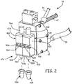
- FIG. 2 is a perspective view of dispenser 34 of FIG. 1 comprising hot melt manifold 40 coupled to dispense modules 42A and 42B, which include an internal valve tip filter of the present invention.
- manifold 40 includes inlet ports for receiving melted hot melt adhesive from supply hose 38, compressed air from air line 46 and control and power wires from conduit 47.
- Manifold 40 supplies both melted hot melt adhesive and compressed air to modules 42A and 42B.
- Modules 42A and 42B includes module housings 48A and 48B, which are connected to manifold 40 via fasteners 50A and 51A, and 50B and 51B, respectively.
- Modules 42A and 42B also include tips 53A and 53B, respectively.
- Module housing 48A comprises valve body 52A, which is connected to tip cap 54A and actuation cap 56A.
- Module housing 48B comprises valve body 52B, which is connected to tip cap 54B and actuation cap 56B.
- Actuation caps 56A and 56B provide access to valve stems within valve bodies 52A and 52B.
- Actuation caps 56A and 56B may also include vent ports (not shown) for discharging compressed air from air line 46 used to actuate the valve stems.
- Tip caps 54A and 54B include discharge ports 58A and 58B, respectively, which, in one embodiment, include valve seats having orifices that receive the tip of the valve stem.
- Tip caps 54A and 54B provide access to filters within valve bodies 52A and 52B.
- compressed air from air line 46 actuates the valve stems to open a hot melt fluid passageway from supply hose 38, manifold 40, module housings 48A and 48B and discharge ports 58A and 58B.
- the present invention relates to filters that are positioned within module housings 48A and 48B to prevent debris, such as charred hot melt material from clogging or plugging discharge ports 58A and 58B, or tips 53A and 53B.
- FIG. 3 is a cross-sectional view of module housing 48A of FIG. 2 showing tip filter 60 surrounding valve stem 62.
- Module housing 48A includes valve body 52A, which is connected to tip cap 54A and actuation cap 56A.
- Valve body 52A includes actuation portion 64 and valve portion 66.
- Actuation portion 64 includes slot 68, air inlet port 70, air port 72 and air seal bore 73.
- Valve portion 66 includes adhesive inlet port 74, valve passage 76 and adhesive seal bore 78. Seals 79A and 79B sit within seal bores 73 and 78, respectively, to seal around valve stem 62.
- Valve stem 62 extends through bore 81 in valve housing 52A to intersect air port 72 and valve passage 76.
- Tip cap 54A includes collar 80 and discharge port 58A, which includes lower valve passage 82.
- Lower valve passage 82 includes counterbore 84 that forms edge 86.
- Tip cap 54A further includes seal 88, which is disposed in channel 90, and seat 92, which engages base 94 in lower valve passage 82.
- Seat 92 includes orifice 96, which aligns with opening 98 in discharge port 58A.
- Actuation cap 56A includes plug 100 and tower 102.
- Spring 104 is positioned within tower 102.
- Plug 100 joins to actuation portion 64 to position spring 104 against piston 106, which is coupled to valve stem 62.
- Filter 60 includes seal ring 108, frame 110, window section 112 and filter media 114.
- Slot 68 comprises a channel in which heads of fasteners 50A, 50B, 51A and 51B ( FIG. 2 ) are disposed when used to join module housing 48A to manifold 40 ( FIG. 2 ).
- air inlet port 70 and adhesive inlet port 74 are pressed against discharge ports (not shown) in manifold 40 ( FIG. 2 ) to receive compressed air and molten hot melt adhesive, respectively.
- Seals 116A and 116B which can be embedded within channels in valve body 52A, are positioned around air inlet port 70 and adhesive inlet port 74 to prevent leaking of fluids from between manifold 40 and module housing 48A.
- Plug 100 of actuation cap 56A holds tower 102 in engagement with valve body 52A to bias spring 104 against piston 106.
- Collar 80 of tip cap 54A holds discharge port 58A in engagement with valve body 52A to maintain seat 92 in a fixed position.
- spring 104 pushes valve stem 62 into engagement with seat 92 to prevent molten hot melt material from being discharged from module housing 48B.
- valve stem 62 Flow of compressed air from compressed air source 16 ( FIG. 1 ) to module housing 48B is controlled by controller 18 ( FIG. 1 ) to actuate valve stem 62 for desired intervals, thereby dispensing a corresponding amount of molten hot melt adhesive.
- Compressed air from air inlet port 70 enters air port 72 and pushes piston 106 upwards (with reference to FIG. 3 ) to compress spring 104.
- valve stem 62 is moved upward so that ball tip 119 of valve stem 62 is lifted from seat 92. This permits molten hot melt material from adhesive inlet port 74 to flow from valve passage 76 out orifice 96 and opening 98 in tip cap 54A.
- Seal 79A surrounds shaft 120 of valve stem 62 within actuation portion 64 and prevents air from entering valve portion 66.
- seal 79B surrounds shaft 120 within valve portion 66 and prevents hot melt material from entering actuation portion 64.
- Filter 60 is positioned within valve body 52A to catch small particles of dust, dirt, char and the like before they are allowed to reach seat 92 and potentially form a clog. Filter 60 is maintained in position relative to adhesive inlet port 74 and valve stem 62 by engagement with tip cap 54A. Collar 80 of tip cap 54A extends into valve passage 76. Rim 124 joins collar 80 and discharge port 58A, and provides a plate through which fasteners 126 extend to join tip cap 54A to valve body 52A. Discharge port 58A extends from collar 80 such that lower valve passage 82 extends from counterbore 84. Seat 92 is positioned within lower valve passage 82 and includes orifice 96 that aligns with opening 98 of discharge port 58A.
- Valve stem 62 extends through filter 60 and into lower valve passage 82 such that ball tip 119 engages orifice 96 in seat 92.
- ball tip 119 is coupled to shaft 120 such as by using a brazed joint.
- Filter 60 is inserted into collar 80, which includes counterbore 84 that forms ledge 86 upon which frame 110 rests.
- Collar 80 is inserted into valve passage 76 such that valve stem 62 is inserted into frame 110.
- collar 80 comprises a cylindrical structure wherein its outer diameter surface engages tightly with valve passage 76 and its inner diameter structure engages tightly with frame 110. Furthermore, collar 80 may be threaded into valve passage 76.
- Frame 110 and filter media 114 of filter 60 surround shaft 120 of valve stem 62 within valve passage 76.
- Seal ring 108 of frame 110 is positioned within valve passage 76 in proximity to seal 79B. Seal ring 108 is positioned upstream of fluid inlet 74. Seal ring 108 also includes bore 122 that permits valve stem 62 to enter into bearing 110. Bore 122 serves as a bearing or guide-hole that facilitates alignment of ball tip 119 with orifice 96.
- Seal ring 108 comprises a rim around the outside of frame 110 that engages the wall of valve passage 76 to assist seal 79B in preventing molten hot melt material from passing out of valve passage 76 through bore 81 in valve body 52A.
- Filter media 114 surrounds a portion of frame 110 in which window section 112 is disposed. Filter media 114 extends across fluid inlet 74.
- filter 60 comprises an outside-in filter in which filtered matter is prevented from entering filter 60 and is left outside of filter 60. More specifically, molten hot melt material passes through filter media 114 from the outside and passes into the interior of frame 110 through windows formed by window portion 112. Once inside filter 60, molten hot melt material passes through an open end of frame 110 and into discharge port 58A and opening 98. Debris and particles screened-out by filter media 114 collect within valve body 52A between filter media 114 and the surfaces of valve passage 76. Tip cap 54A is removed from valve body 52A to clean or replace filter media 114 and remove collected particles from inside valve body 52A.
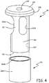
- FIG. 4 an exploded perspective view of tip filter 60 of FIG. 3 wherein filter media 114 is positioned around frame 110.
- Frame 110 comprises a cylindrical body that is closed at one end by connection to plate 128 and is open at a second end that is distal to the first end. The second end forms outlet 130.
- Internal wall 132 forms a passage between plate 128 and outlet 130.
- Outlet 130 is disposed at a full-hoop end section of frame 110.
- Seal ring 108 circumscribes plate 128 to form a ledge around frame 110.
- Bore 118 extends through plate 128 to connect to the passage produced by internal wall 132.
- Window section 112 of frame 110 comprises a plurality of sections of frame 110 in between windows 134A and 134B. In the embodiment depicted, window section 112 comprises three windows (of which only two are seen in FIG. 4 ) spaced equally around the circumference of frame 110.
- Filter media 114 is formed into a cylindrical body that is fit over frame 110. More specifically, filter media 114 is fit over window section 112. Filter media 114 can be force fit over frame 110 such that filter media 114 is held firmly in place within valve body 52A. Filter media 114 may also be adhered or fastened to frame 110. Filter media 114 may comprise any suitable filtration media as is known in the art. For example, filter media 114 may comprise metal or non-metal wire meshes, metal or non-metal wools, sintered materials, or ceramic materials. In one embodiment, filter media 114 comprises a double-layer of filtration media wherein outer diameter layer 136A includes a coarser level of filtration as compared to inner diameter layer 136B.
- Windows 134A and 134B are positioned on frame 110 such that, when filter 60 is assembled inside valve body 52A, the windows are positioned across from adhesive inlet port 74. As such, molten hot melt material flows through filter media 114 and windows 134A and 134B, and into the passage formed by internal wall 132. Debris is filtered out of the interior of filter 60. Filter media 114 can be removed from frame 110 for cleaning or replacement, or filter 60 in its entirety can be replaced.
- FIG. 5 is a cross-sectional view of another embodiment of a dispense module showing a first embodiment of an inside-out tip filter surrounding a valve stem.
- Dispense module 140 includes valve body 142 and tip body 144.
- Valve body 142 includes slot 146, discharge port 148, valve bore 150, fluid inlet port 152, upper valve passage 154 and seal seat 156.
- Tip body 144 includes collar 158 and lower valve passage 160, which includes counterbore 162 that forms edge 164.
- Tip body 144 is coupled to seal 168, which is disposed in channel 170, and tip 164, which engages shelf 166 in lower valve passage 160.
- Filter 172 surrounds valve stem 174 and includes seal ring 176, filter media 178 and bearing 180.
- Slot 146 joins to a mating flange on a manifold to assist in aligning holes for the flow of melted hot melt material and compressed air between manifold 40 and module 42 ( FIG. 1 ).
- Collar 158 of tip body 144 is inserted into upper valve passage 154 of valve body 152.
- Seal 168 is positioned between collar 158 and upper valve passage 154 to prevent leakage of fluid from between valve body 142 and tip body 144.
- Tip 164 is positioned within lower valve passage 160 and includes a flange or lip that engages shelf 166 to prevent tip 164 from passing through lower valve passage 160.
- Tip 164 comprises an annular body having orifice 182.
- Tip 164 and tip body 144 function similarly to tip cap 54A and discharge port 158A of FIG. 3 .
- Filter 172 is positioned within couterbore 162 of lower valve passage 160 such that seal ring 176 sits atop collar 158.
- bearing 180 comprises a hoop from which prongs 184A, 184B and 184C ( FIG. 7 ) extend. Prongs 184A - 184C are configured to rest on edge 165.
- bearing 180 includes three prongs that are spaced equally apart around bearing 160 such that counterbore 162 remains in fluid communication with lower valve passage 160.
- prongs 184A and 184B are spaced from edge 165 and only engage edge 165 if filter media 178 becomes stretched or deformed. Filter media 178 connects seal ring 176 with bearing 180.
- Valve stem 174 extends through discharge port 148 and bore 152, through upper valve passage 154, through filter 60 and into tip 164 to engage orifice 182. Assembled as such, a fluid path is formed between fluid inlet 152 and orifice 184 that passes through filter 172.
- Valve stem 174 is retracted from orifice 184 to permit flow of molten hot melt material through the fluid path between fluid inlet 152 and orifice 184.
- a valve actuator (not shown), as is known in the art, is connected to valve stem 174 to linearly displace valve stem 174.
- Discharge port 148 releases compressed air used to actuate valve stem 174.
- Molten hot melt adhesive from fluid inlet 152 flows into upper valve passage 154.
- a seal such as a U-cup seal, can be positioned within seal bore 156 to prevent molten hot melt material from passing into discharge port 148. The molten hot melt material then flows into seal ring 176 to an interior space defined by filter media 178.
- Seal ring 176 rests atop collar 158 and the outer diameter of seal ring 176 can engage surfaces of upper valve passage 154 to prevent molten hot melt material from bypassing filter 172. Molten hot melt material then flows through filter media 178 and around the outside of bearing 180, passing between prongs 184A and 184B. Finally, molten hot melt material flow through lower valve passage 160 and into tip 164, whereby the material can exit dispense module 140 when valve stem 174 is retracted away from orifice 182.
- filter 172 comprises an inside-out filter in which filtered matter is prevented from leaving filter 172 and is left inside of filter 172. More specifically, molten hot melt material passes through filter media 178 from the inside and passes into the interior of tip body 144. Debris and particles screened-out by filter media 178 collect within filter media 178. Tip body 144 is removed from valve body 142 to clean filter media 178 or replace filter 172 and remove collected particles from inside of filter media 178. Filter 172 in its entirety is removed from tip body 144 for cleaning or replacement.
- FIG. 6 is a perspective view of tip filter 172 of FIG. 5 showing filter media 178 having seal ring 176 disposed at an upper end and internal bearing 180 disposed at a lower end.
- FIG. 7 is a bottom view of tip filter 172 of FIG. 6 showing prongs 184A - 184C extending from internal bearing 180.
- Filter media 178 comprises a double-layer of filtration media comprising outer layer 186 and inner layer 188. In other embodiments filter media 178 may be only a single layer.
- Seal ring 176 and internal bearing 180 are joined to filter media 178 using various methods. In embodiment disclosed with reference to FIG. 6 , seal ring 176 and internal bearing 180 are brazed or welded to filter media 178. In such an embodiment, seal ring 176, filter media 178 and internal bearing 180 are formed of metals, metal alloys or other metallic materials.
- Seal ring 176 comprises an annular body that is attached to an edge of filter media 178.
- seal ring 176 comprises a ring having a rectilinear cross-section. Such a configuration allows seal ring 176 to rest flush on collar 158 of tip body 144 ( FIG. 5 ). Additionally, as can be seen in FIG. 5 , the rectilinear configuration allows seal ring 176 to extend flush across filter media 178, which facilitates attachment of seal ring 176 to filter media 178.
- internal bearing 180 comprises a generally triangular body that forms three points, which correspond to three prongs 184A - 184C.
- Valve bore 190 ( FIG. 7 ) extends through internal bearing 180 to allow valve stem 174 ( FIG. 5 ) to pass through filter 172 and internal bearing 180.
- valve bore 190 is sized to form a slip fit that permits valve stem 174 to slide freely within bore 190. However, the gap between valve stem 174 and valve bore 190 is smaller than the mesh or filtration size filter 172.
- Prongs 184A - 184C extend from the lower (with reference to the orientation of FIG. 6 ) surface of internal bearing 180 so as to provide intermittent extensions that engage edge 164 ( FIG. 5 ) to prevent filter 172 from falling into lower valve passage 160 ( FIG. 5 ).
- internal bearing 180 facilitates central alignment of valve stem 172 within filter 172 and lower valve passage 160 to provide proper engagement with orifice 182 in tip 164 ( FIG. 5 ).
- Prongs 184A - 184C are intermittent so as to not encompass the entire circumference of internal bearing 180. Thus, molten hot melt material from within filter media 178 is permitted to pass around the outside of internal bearing 180.
- Internal bearing 180 may have other configurations that produce intermittent engagement with counterbore 184 and edge 164.
- internal bearing may be square shaped having four prongs extending from the four corners of a square body.
- FIG. 8 is a cross-sectional view of dispense module 140 showing a second embodiment of inside-out tip filter 191 comprising injection molded seal rings 192A and 192B and internal bearing 194.
- Valve body 142 and tip body 144 of dispense module 140 are the same as those of FIG. 5 .
- Seal rings 192A and 192 are manufactured directly onto filter media 196, which is substantially similar to filter media 178 of FIG. 5 .
- seal rings 192A and 192B may be directly injection molded onto filter media 196.
- seal rings 192A and 192B may be formed of a plastic or polymer material.
- seal rings 192A and 192B may be cast onto filter media 196 and may be formed of metal, metal alloys or metallic materials.
- Seal ring 192A performs the same function as that of seal ring 176 of FIG. 5 . Specifically, seal ring 192A rests on tip body 144 to support filter 191. Seal ring 192B serves as a mating piece for joining internal bearing 194 to filter media 196. For example, seal ring 192B is integrally joined to filter media 196 and thereby serves as a stiffener for filter media 196. Seal ring 192B also permits internal bearing 194 to be mechanically joined, such as through a force fit or snap fit, to filter 191. Filter 191 collects particles within filter media 196 and the entirety of filter 191 is removed from tip body 144 for cleaning or replacement.
- FIG. 9 is a cross-sectional view of a third embodiment of inside-out tip filter 198 in which filter media 200 is mechanically connected to external bearing 202.
- External bearing 202 comprises bearing body 204 and support body 206.
- Filter 198 is supported within dispense module 140 ( FIG. 5 ) via flange 207 surrounding filter media 200.
- Flange 207 comprises a portion of filter media 200 that is bent radially outward (with reference to a central axis extending through the interior of filter media 200) so as to be able to engage collar 158 ( FIG. 5 ).
- filter 198 is suspended within dispense module 140 via flange 207, similarly to how seal ring 176 functions.
- Bearing body 204 comprises a cylindrical piece that can be fitted into filter media 200.
- Bearing body 204 includes valve bore 208 for receiving valve stem 174 ( FIG. 8 ).
- the outer diameter of bearing body 204 also includes ridges 210.
- Support body 206 includes internal bore 214 into which filter media 200 is inserted from one end and into which bearing body 204 is inserted from the opposite end.
- Support body 206 also includes prongs 216A and 216B, which function similarly as prongs 184A and 184B ( FIG. 5 ) to engage edge 164 ( FIG. 5 ).
- support body 206 includes slots 218, which are configured to engage with ridges 210 of bearing body 204.
- bearing body 204 is pushed into support body 206 such that ridges 210 and slots 218 are tightly engaged. Ridges 210 and slots 218 may be configured as a spline that engages over a force fit or snap fit.
- bearing body 204 and support body 206 may be joined by a threaded engagement. With bearing body 204 and support body 206 assembled as such, filter media 200 is pinched therebetween causing external bearing 202 to be mechanically joined to filter media 200. Bearing body 204 can be removed from support body 206 so that filter media 200 can be cleaned or replaced. Alternatively, the entirety of filter 198 can be discarded and replaced.
Landscapes
- Coating Apparatus (AREA)
- Filtering Of Dispersed Particles In Gases (AREA)
- Adhesives Or Adhesive Processes (AREA)
- Details Of Valves (AREA)
- Nozzles (AREA)
Applications Claiming Priority (3)
| Application Number | Priority Date | Filing Date | Title |
|---|---|---|---|
| US201161576011P | 2011-12-15 | 2011-12-15 | |
| PCT/US2012/061919 WO2013089918A1 (fr) | 2011-12-15 | 2012-10-25 | Filtre pour embout de valve interne |
| EP12858002.4A EP2790839B1 (fr) | 2011-12-15 | 2012-10-25 | Filtre pour embout de valve interne |
Related Parent Applications (1)
| Application Number | Title | Priority Date | Filing Date |
|---|---|---|---|
| EP12858002.4A Division EP2790839B1 (fr) | 2011-12-15 | 2012-10-25 | Filtre pour embout de valve interne |
Publications (2)
| Publication Number | Publication Date |
|---|---|
| EP3689471A1 true EP3689471A1 (fr) | 2020-08-05 |
| EP3689471B1 EP3689471B1 (fr) | 2023-12-13 |
Family
ID=48609101
Family Applications (2)
| Application Number | Title | Priority Date | Filing Date |
|---|---|---|---|
| EP20166368.9A Active EP3689471B1 (fr) | 2011-12-15 | 2012-10-25 | Filtre d'extrémité de soupape interne |
| EP12858002.4A Active EP2790839B1 (fr) | 2011-12-15 | 2012-10-25 | Filtre pour embout de valve interne |
Family Applications After (1)
| Application Number | Title | Priority Date | Filing Date |
|---|---|---|---|
| EP12858002.4A Active EP2790839B1 (fr) | 2011-12-15 | 2012-10-25 | Filtre pour embout de valve interne |
Country Status (9)
| Country | Link |
|---|---|
| US (1) | US8893930B2 (fr) |
| EP (2) | EP3689471B1 (fr) |
| JP (1) | JP2015510566A (fr) |
| KR (1) | KR20140106678A (fr) |
| CN (1) | CN104010733B (fr) |
| ES (1) | ES2972296T3 (fr) |
| MX (1) | MX2014006531A (fr) |
| TW (1) | TW201323756A (fr) |
| WO (1) | WO2013089918A1 (fr) |
Families Citing this family (17)
| Publication number | Priority date | Publication date | Assignee | Title |
|---|---|---|---|---|
| MX341164B (es) * | 2011-10-27 | 2016-08-10 | Graco Minnesota Inc | Mecanismo de apoyo de alimentacion del sistema de vacio. |
| US8936178B2 (en) * | 2012-11-29 | 2015-01-20 | Nordson Corporation | Adhesive melter having quick change pump pack assembly and associated methods |
| WO2016069870A1 (fr) * | 2014-10-31 | 2016-05-06 | Graco Minnesota Inc. | Joint d'étanchéité contre des fluides à soufflet |
| CN105854388B (zh) * | 2016-05-17 | 2018-02-02 | 安徽铜冠机械股份有限公司 | 陶瓷过滤机中心定位轴承式分配阀 |
| US10471461B2 (en) * | 2017-03-01 | 2019-11-12 | Nordson Corporation | Liquid dispensing module |
| FR3065889B1 (fr) * | 2017-05-04 | 2021-12-17 | Aptar France Sas | Tete de distribution de produit fluide et ensemble de moulage d'une telle tete |
| CN108097480A (zh) * | 2018-01-30 | 2018-06-01 | 中国五冶集团有限公司 | 一种丝扣油喷涂的喷嘴结构 |
| JP7021575B2 (ja) * | 2018-03-16 | 2022-02-17 | マツダ株式会社 | 多液混合装置 |
| JP7102811B2 (ja) * | 2018-03-16 | 2022-07-20 | マツダ株式会社 | 流動材料供給装置 |
| DE102018108915A1 (de) * | 2018-04-16 | 2019-10-17 | Atlas Copco Ias Gmbh | Dosierventil |
| US20200070194A1 (en) * | 2018-08-29 | 2020-03-05 | Skypath, Llc | Modified impingement spray nozzle |
| CN109218672B (zh) * | 2018-09-19 | 2020-12-22 | 山东六脉网络科技有限公司 | 一种基于区块链技术的智能监控装置 |
| CN109569915B (zh) * | 2019-01-03 | 2023-10-31 | 美安士工业科技(上海)有限公司 | 一种喷头 |
| US11666932B2 (en) | 2020-03-27 | 2023-06-06 | Wagner Spray Tech Corporation | Fluid applicator |
| US12138651B2 (en) | 2020-03-27 | 2024-11-12 | Wagner Spray Tech Corporaton | Fluid applicator |
| DE102020123966A1 (de) * | 2020-09-15 | 2022-03-17 | Atlas Copco Ias Gmbh | Verfahren zum Zusammenbau eines Nadelventils |
| JP7553316B2 (ja) * | 2020-10-14 | 2024-09-18 | トヨタ自動車東日本株式会社 | 塗料噴射ノズル |
Citations (4)
| Publication number | Priority date | Publication date | Assignee | Title |
|---|---|---|---|---|
| US5598974A (en) * | 1995-01-13 | 1997-02-04 | Nordson Corporation | Reduced cavity module with interchangeable seat |
| DE29703049U1 (de) * | 1996-02-28 | 1997-04-17 | Massimo Brusa, Oemmebi di, Trezzano Sul Naviglio | Automatisches Hochdruckgerät zur Abgabe flüssiger Substanzen |
| EP1117486A1 (fr) * | 1998-10-02 | 2001-07-25 | Nordson Corporation | Buse de distribution, pistolet, filtre et procede utilisant des identificateurs visuels indiquant la taille d'orifice et la longueur de manchon |
| US6799702B1 (en) * | 2000-11-22 | 2004-10-05 | Gopro, Inc. | Device for dispensing viscous liquids |
Family Cites Families (43)
| Publication number | Priority date | Publication date | Assignee | Title |
|---|---|---|---|---|
| US2524820A (en) | 1946-05-11 | 1950-10-10 | Gen Electric | Liquid atomizing nozzle |
| US2631892A (en) | 1950-02-21 | 1953-03-17 | Eddington Metal Specialty Comp | Oil burner filter |
| US2664312A (en) | 1950-02-21 | 1953-12-29 | Eddington Metal Specialty Comp | Oil burner filter |
| US2637194A (en) | 1952-07-03 | 1953-05-05 | Pietri Adolph Victor | Valise with permutation lock |
| US2705663A (en) | 1952-08-08 | 1955-04-05 | Robert I Gilbreath | Spray gun |
| US2967112A (en) | 1958-03-11 | 1961-01-03 | Pilkington Brothers Ltd | Method and apparatus for applying metal-depositing solutions |
| US3065918A (en) | 1959-11-03 | 1962-11-27 | Stewart Warner Corp | High pressure paint spray gun |
| GB995142A (en) * | 1961-06-28 | 1965-06-16 | Lucas Industries Ltd | Filters |
| DE1459519A1 (de) * | 1961-12-14 | 1969-02-06 | Karrer Weber & Cie Ag | Von Strahl auf Brause umstellbarer Strahlregler |
| US3317141A (en) | 1964-10-26 | 1967-05-02 | Mann Carl | Airless liquid spray gun having a diaphragm pump and filtering apparatus |
| US3752400A (en) | 1970-05-22 | 1973-08-14 | O Calder | Combined spray and anti-clogging means |
| US3708118A (en) | 1971-04-19 | 1973-01-02 | Dick Co Ab | Filtering apparatus for a drop writing system |
| US3889881A (en) | 1974-05-29 | 1975-06-17 | Lonnie C Cunningham | Liquid dispersal apparatus |
| DE2724931A1 (de) | 1976-06-21 | 1977-12-29 | Lonza Ag | Vorrichtung zum verspruehen von dispersen systemen |
| US4598841A (en) | 1983-07-12 | 1986-07-08 | Nordson Corporation | Thermoplastic dispensing gun having a self-contained filter and flow control valve |
| US4655398A (en) | 1983-12-19 | 1987-04-07 | Goodyear Aerospace Corporation | Spraying apparatus for in situ formation of vehicle fuel tanks |
| US4613079A (en) | 1984-10-25 | 1986-09-23 | Parker-Hannifin Corporation | Fuel nozzle with disc filter |
| US4667884A (en) | 1985-04-01 | 1987-05-26 | Braziel Bobby G | Paint gun tip filter, atomizer and gasket combination |
| US4882055A (en) * | 1986-09-11 | 1989-11-21 | Suratco Products Company | Unitary injection molded filter |
| JPS63275870A (ja) | 1987-05-01 | 1988-11-14 | Taisan Kogyo Kk | 流量制御ノズル |
| US5013415A (en) * | 1989-05-12 | 1991-05-07 | Hudson Wilbur N | Liquid purification system |
| JPH03119404U (fr) * | 1990-03-13 | 1991-12-10 | ||
| US5044555A (en) | 1990-07-23 | 1991-09-03 | Herrmidifier Company, Inc. | Self-cleaning solenoid controlled water spray nozzle and valve assembly |
| US5829644A (en) * | 1997-01-07 | 1998-11-03 | Brightwell; Edgar Neil | Wine and cork separator |
| US5875922A (en) * | 1997-10-10 | 1999-03-02 | Nordson Corporation | Apparatus for dispensing an adhesive |
| DE19807922A1 (de) * | 1998-02-25 | 1999-08-26 | Pfeiffer Erich Gmbh & Co Kg | Spender für Medien |
| US6168049B1 (en) | 1999-11-03 | 2001-01-02 | Illinois Tool Works Inc. | Hot melt adhesive applicator with centrally located filter |
| US6315168B1 (en) | 2000-05-24 | 2001-11-13 | Illinois Tool Works Inc. | Removable inline nozzle filter |
| DE10063285A1 (de) * | 2000-12-19 | 2002-06-20 | Ina Schaeffler Kg | Siebfilter für Fluidleitungen, insbesondere für hydraulische Druckleitungen in Brennkraftmaschinen |
| US6722508B2 (en) * | 2002-05-15 | 2004-04-20 | Eaton Corporation | Removable cartridge assembly for filtering bi-directional axial flow and radial flow and method of making same |
| US8069653B2 (en) * | 2002-10-16 | 2011-12-06 | Nordson Corporation | Interchangeable nozzle for a dispensing module |
| US6874708B2 (en) | 2003-02-13 | 2005-04-05 | Illinois Tool Works Inc. | Automatic air-assisted manifold mounted gun |
| CN2727509Y (zh) * | 2003-12-18 | 2005-09-21 | 许俊杰 | 多功能一体化组合电磁阀 |
| KR100531475B1 (ko) | 2003-12-27 | 2005-12-02 | 이서구 | 핫 멜트 분사장치 |
| JP4606757B2 (ja) * | 2004-03-15 | 2011-01-05 | 三菱電機株式会社 | Egrバルブ装置 |
| US7264717B2 (en) * | 2004-04-22 | 2007-09-04 | Nordson Corporation | Liquid dispensing apparatus and a filter assembly for a liquid dispensing apparatus |
| DE102004058803A1 (de) * | 2004-12-07 | 2006-06-08 | Robert Bosch Gmbh | Einspritzventil |
| US7182229B2 (en) * | 2004-12-22 | 2007-02-27 | Nordson Corporation | Device for dispensing liquid having an improved seal assembly |
| WO2007084891A2 (fr) * | 2006-01-17 | 2007-07-26 | Nordson Corporation | Appareil et procédé de fusion et de distribution de matière thermoplastique |
| US7614529B2 (en) | 2006-04-24 | 2009-11-10 | Illinois Tool Works Inc. | Spool valve and valve seat assembly for an intermittently operable hot melt adhesive material control module |
| DE202006016674U1 (de) | 2006-10-27 | 2007-02-22 | Nordson Corporation, Westlake | Auftragsvorrichtung zum Auftragen von flüssigem Material |
| US20080217360A1 (en) | 2007-03-05 | 2008-09-11 | Illinois Tool Works Inc. | Hot melt adhesive dispensing valve or module assembly having a module filter disposed therewithin |
| CN102105203A (zh) * | 2008-06-20 | 2011-06-22 | 帕克过滤股份有限公司 | 过滤器组件 |
-
2012
- 2012-10-25 KR KR1020147019152A patent/KR20140106678A/ko not_active Withdrawn
- 2012-10-25 CN CN201280062177.3A patent/CN104010733B/zh not_active Expired - Fee Related
- 2012-10-25 US US13/660,094 patent/US8893930B2/en active Active
- 2012-10-25 JP JP2014547228A patent/JP2015510566A/ja not_active Ceased
- 2012-10-25 ES ES20166368T patent/ES2972296T3/es active Active
- 2012-10-25 EP EP20166368.9A patent/EP3689471B1/fr active Active
- 2012-10-25 WO PCT/US2012/061919 patent/WO2013089918A1/fr not_active Ceased
- 2012-10-25 EP EP12858002.4A patent/EP2790839B1/fr active Active
- 2012-10-25 MX MX2014006531A patent/MX2014006531A/es not_active Application Discontinuation
- 2012-10-26 TW TW101139818A patent/TW201323756A/zh unknown
Patent Citations (4)
| Publication number | Priority date | Publication date | Assignee | Title |
|---|---|---|---|---|
| US5598974A (en) * | 1995-01-13 | 1997-02-04 | Nordson Corporation | Reduced cavity module with interchangeable seat |
| DE29703049U1 (de) * | 1996-02-28 | 1997-04-17 | Massimo Brusa, Oemmebi di, Trezzano Sul Naviglio | Automatisches Hochdruckgerät zur Abgabe flüssiger Substanzen |
| EP1117486A1 (fr) * | 1998-10-02 | 2001-07-25 | Nordson Corporation | Buse de distribution, pistolet, filtre et procede utilisant des identificateurs visuels indiquant la taille d'orifice et la longueur de manchon |
| US6799702B1 (en) * | 2000-11-22 | 2004-10-05 | Gopro, Inc. | Device for dispensing viscous liquids |
Also Published As
| Publication number | Publication date |
|---|---|
| ES2972296T3 (es) | 2024-06-12 |
| WO2013089918A1 (fr) | 2013-06-20 |
| EP2790839B1 (fr) | 2020-04-22 |
| CN104010733B (zh) | 2017-05-24 |
| KR20140106678A (ko) | 2014-09-03 |
| MX2014006531A (es) | 2014-07-14 |
| CN104010733A (zh) | 2014-08-27 |
| EP2790839A1 (fr) | 2014-10-22 |
| EP2790839A4 (fr) | 2015-10-14 |
| JP2015510566A (ja) | 2015-04-09 |
| TW201323756A (zh) | 2013-06-16 |
| EP3689471B1 (fr) | 2023-12-13 |
| US8893930B2 (en) | 2014-11-25 |
| US20130153604A1 (en) | 2013-06-20 |
Similar Documents
| Publication | Publication Date | Title |
|---|---|---|
| US8893930B2 (en) | Internal valve tip filter | |
| US8939330B2 (en) | Removable module service seat | |
| CN103974781B (zh) | 熔炉 | |
| US8985391B2 (en) | Vacuum system feed assist mechanism | |
| US9169088B2 (en) | Adhesive dispensing device having optimized cyclonic separator unit | |
| EP2303466B1 (fr) | Connecteur pour un pistolet vaporisateur à alimentation par gravité, pistolet vaporisateur à alimentation par gravité, et procédé de préparation d une peinture vaporisée | |
| EP1424135A1 (fr) | Pistolet pulvérisateur manuel et réservoir associé | |
| CN105682807B (zh) | 用于分配粘结剂的分配模块和方法 | |
| TW201341296A (zh) | 可逆之流體引導器 | |
| US7938299B2 (en) | Device for attaching a dip tube to a fluid container | |
| US20130112294A1 (en) | Hot melt tank and check valve | |
| CN100413599C (zh) | 热熔性粘合剂配料器 | |
| US7264717B2 (en) | Liquid dispensing apparatus and a filter assembly for a liquid dispensing apparatus | |
| CN106999963B (zh) | 波纹管流体密封件 | |
| CN107073507B (zh) | 快速释放螺线管组件 | |
| US20140120254A1 (en) | Feed cap | |
| US20140166125A1 (en) | Melter with tank shaker | |
| WO2014092731A1 (fr) | Appareil de fusion doté d'un agitateur de cuve |
Legal Events
| Date | Code | Title | Description |
|---|---|---|---|
| PUAI | Public reference made under article 153(3) epc to a published international application that has entered the european phase |
Free format text: ORIGINAL CODE: 0009012 |
|
| STAA | Information on the status of an ep patent application or granted ep patent |
Free format text: STATUS: THE APPLICATION HAS BEEN PUBLISHED |
|
| AC | Divisional application: reference to earlier application |
Ref document number: 2790839 Country of ref document: EP Kind code of ref document: P |
|
| AK | Designated contracting states |
Kind code of ref document: A1 Designated state(s): AL AT BE BG CH CY CZ DE DK EE ES FI FR GB GR HR HU IE IS IT LI LT LU LV MC MK MT NL NO PL PT RO RS SE SI SK SM TR |
|
| RIN1 | Information on inventor provided before grant (corrected) |
Inventor name: SPIESS, ANDREW Inventor name: LIHWA, JOHN S Inventor name: TIX, JOSEPH E Inventor name: ROSS, DANIEL P Inventor name: WEINBERGER, MARK T Inventor name: QUAM, PAUL R |
|
| STAA | Information on the status of an ep patent application or granted ep patent |
Free format text: STATUS: REQUEST FOR EXAMINATION WAS MADE |
|
| 17P | Request for examination filed |
Effective date: 20210113 |
|
| RBV | Designated contracting states (corrected) |
Designated state(s): AL AT BE BG CH CY CZ DE DK EE ES FI FR GB GR HR HU IE IS IT LI LT LU LV MC MK MT NL NO PL PT RO RS SE SI SK SM TR |
|
| STAA | Information on the status of an ep patent application or granted ep patent |
Free format text: STATUS: EXAMINATION IS IN PROGRESS |
|
| 17Q | First examination report despatched |
Effective date: 20211020 |
|
| GRAP | Despatch of communication of intention to grant a patent |
Free format text: ORIGINAL CODE: EPIDOSNIGR1 |
|
| STAA | Information on the status of an ep patent application or granted ep patent |
Free format text: STATUS: GRANT OF PATENT IS INTENDED |
|
| INTG | Intention to grant announced |
Effective date: 20230629 |
|
| GRAS | Grant fee paid |
Free format text: ORIGINAL CODE: EPIDOSNIGR3 |
|
| GRAA | (expected) grant |
Free format text: ORIGINAL CODE: 0009210 |
|
| STAA | Information on the status of an ep patent application or granted ep patent |
Free format text: STATUS: THE PATENT HAS BEEN GRANTED |
|
| P01 | Opt-out of the competence of the unified patent court (upc) registered |
Effective date: 20231026 |
|
| AC | Divisional application: reference to earlier application |
Ref document number: 2790839 Country of ref document: EP Kind code of ref document: P |
|
| AK | Designated contracting states |
Kind code of ref document: B1 Designated state(s): AL AT BE BG CH CY CZ DE DK EE ES FI FR GB GR HR HU IE IS IT LI LT LU LV MC MK MT NL NO PL PT RO RS SE SI SK SM TR |
|
| REG | Reference to a national code |
Ref country code: GB Ref legal event code: FG4D |
|
| REG | Reference to a national code |
Ref country code: CH Ref legal event code: EP |
|
| REG | Reference to a national code |
Ref country code: DE Ref legal event code: R096 Ref document number: 602012080416 Country of ref document: DE |
|
| REG | Reference to a national code |
Ref country code: IE Ref legal event code: FG4D |
|
| PG25 | Lapsed in a contracting state [announced via postgrant information from national office to epo] |
Ref country code: GR Free format text: LAPSE BECAUSE OF FAILURE TO SUBMIT A TRANSLATION OF THE DESCRIPTION OR TO PAY THE FEE WITHIN THE PRESCRIBED TIME-LIMIT Effective date: 20240314 |
|
| REG | Reference to a national code |
Ref country code: LT Ref legal event code: MG9D |
|
| PG25 | Lapsed in a contracting state [announced via postgrant information from national office to epo] |
Ref country code: LT Free format text: LAPSE BECAUSE OF FAILURE TO SUBMIT A TRANSLATION OF THE DESCRIPTION OR TO PAY THE FEE WITHIN THE PRESCRIBED TIME-LIMIT Effective date: 20231213 |
|
| REG | Reference to a national code |
Ref country code: NL Ref legal event code: MP Effective date: 20231213 |
|
| PG25 | Lapsed in a contracting state [announced via postgrant information from national office to epo] |
Ref country code: LT Free format text: LAPSE BECAUSE OF FAILURE TO SUBMIT A TRANSLATION OF THE DESCRIPTION OR TO PAY THE FEE WITHIN THE PRESCRIBED TIME-LIMIT Effective date: 20231213 Ref country code: GR Free format text: LAPSE BECAUSE OF FAILURE TO SUBMIT A TRANSLATION OF THE DESCRIPTION OR TO PAY THE FEE WITHIN THE PRESCRIBED TIME-LIMIT Effective date: 20240314 Ref country code: BG Free format text: LAPSE BECAUSE OF FAILURE TO SUBMIT A TRANSLATION OF THE DESCRIPTION OR TO PAY THE FEE WITHIN THE PRESCRIBED TIME-LIMIT Effective date: 20240313 |
|
| REG | Reference to a national code |
Ref country code: AT Ref legal event code: MK05 Ref document number: 1640038 Country of ref document: AT Kind code of ref document: T Effective date: 20231213 |
|
| PG25 | Lapsed in a contracting state [announced via postgrant information from national office to epo] |
Ref country code: NL Free format text: LAPSE BECAUSE OF FAILURE TO SUBMIT A TRANSLATION OF THE DESCRIPTION OR TO PAY THE FEE WITHIN THE PRESCRIBED TIME-LIMIT Effective date: 20231213 |
|
| PG25 | Lapsed in a contracting state [announced via postgrant information from national office to epo] |
Ref country code: SE Free format text: LAPSE BECAUSE OF FAILURE TO SUBMIT A TRANSLATION OF THE DESCRIPTION OR TO PAY THE FEE WITHIN THE PRESCRIBED TIME-LIMIT Effective date: 20231213 Ref country code: RS Free format text: LAPSE BECAUSE OF FAILURE TO SUBMIT A TRANSLATION OF THE DESCRIPTION OR TO PAY THE FEE WITHIN THE PRESCRIBED TIME-LIMIT Effective date: 20231213 Ref country code: NO Free format text: LAPSE BECAUSE OF FAILURE TO SUBMIT A TRANSLATION OF THE DESCRIPTION OR TO PAY THE FEE WITHIN THE PRESCRIBED TIME-LIMIT Effective date: 20240313 Ref country code: NL Free format text: LAPSE BECAUSE OF FAILURE TO SUBMIT A TRANSLATION OF THE DESCRIPTION OR TO PAY THE FEE WITHIN THE PRESCRIBED TIME-LIMIT Effective date: 20231213 Ref country code: LV Free format text: LAPSE BECAUSE OF FAILURE TO SUBMIT A TRANSLATION OF THE DESCRIPTION OR TO PAY THE FEE WITHIN THE PRESCRIBED TIME-LIMIT Effective date: 20231213 Ref country code: HR Free format text: LAPSE BECAUSE OF FAILURE TO SUBMIT A TRANSLATION OF THE DESCRIPTION OR TO PAY THE FEE WITHIN THE PRESCRIBED TIME-LIMIT Effective date: 20231213 |
|
| REG | Reference to a national code |
Ref country code: ES Ref legal event code: FG2A Ref document number: 2972296 Country of ref document: ES Kind code of ref document: T3 Effective date: 20240612 |
|
| PG25 | Lapsed in a contracting state [announced via postgrant information from national office to epo] |
Ref country code: IS Free format text: LAPSE BECAUSE OF FAILURE TO SUBMIT A TRANSLATION OF THE DESCRIPTION OR TO PAY THE FEE WITHIN THE PRESCRIBED TIME-LIMIT Effective date: 20240413 |
|
| PG25 | Lapsed in a contracting state [announced via postgrant information from national office to epo] |
Ref country code: AT Free format text: LAPSE BECAUSE OF FAILURE TO SUBMIT A TRANSLATION OF THE DESCRIPTION OR TO PAY THE FEE WITHIN THE PRESCRIBED TIME-LIMIT Effective date: 20231213 Ref country code: CZ Free format text: LAPSE BECAUSE OF FAILURE TO SUBMIT A TRANSLATION OF THE DESCRIPTION OR TO PAY THE FEE WITHIN THE PRESCRIBED TIME-LIMIT Effective date: 20231213 |
|
| PG25 | Lapsed in a contracting state [announced via postgrant information from national office to epo] |
Ref country code: SK Free format text: LAPSE BECAUSE OF FAILURE TO SUBMIT A TRANSLATION OF THE DESCRIPTION OR TO PAY THE FEE WITHIN THE PRESCRIBED TIME-LIMIT Effective date: 20231213 |
|
| PG25 | Lapsed in a contracting state [announced via postgrant information from national office to epo] |
Ref country code: SM Free format text: LAPSE BECAUSE OF FAILURE TO SUBMIT A TRANSLATION OF THE DESCRIPTION OR TO PAY THE FEE WITHIN THE PRESCRIBED TIME-LIMIT Effective date: 20231213 Ref country code: SK Free format text: LAPSE BECAUSE OF FAILURE TO SUBMIT A TRANSLATION OF THE DESCRIPTION OR TO PAY THE FEE WITHIN THE PRESCRIBED TIME-LIMIT Effective date: 20231213 Ref country code: RO Free format text: LAPSE BECAUSE OF FAILURE TO SUBMIT A TRANSLATION OF THE DESCRIPTION OR TO PAY THE FEE WITHIN THE PRESCRIBED TIME-LIMIT Effective date: 20231213 Ref country code: IS Free format text: LAPSE BECAUSE OF FAILURE TO SUBMIT A TRANSLATION OF THE DESCRIPTION OR TO PAY THE FEE WITHIN THE PRESCRIBED TIME-LIMIT Effective date: 20240413 Ref country code: EE Free format text: LAPSE BECAUSE OF FAILURE TO SUBMIT A TRANSLATION OF THE DESCRIPTION OR TO PAY THE FEE WITHIN THE PRESCRIBED TIME-LIMIT Effective date: 20231213 Ref country code: CZ Free format text: LAPSE BECAUSE OF FAILURE TO SUBMIT A TRANSLATION OF THE DESCRIPTION OR TO PAY THE FEE WITHIN THE PRESCRIBED TIME-LIMIT Effective date: 20231213 Ref country code: AT Free format text: LAPSE BECAUSE OF FAILURE TO SUBMIT A TRANSLATION OF THE DESCRIPTION OR TO PAY THE FEE WITHIN THE PRESCRIBED TIME-LIMIT Effective date: 20231213 |
|
| PG25 | Lapsed in a contracting state [announced via postgrant information from national office to epo] |
Ref country code: PL Free format text: LAPSE BECAUSE OF FAILURE TO SUBMIT A TRANSLATION OF THE DESCRIPTION OR TO PAY THE FEE WITHIN THE PRESCRIBED TIME-LIMIT Effective date: 20231213 Ref country code: PT Free format text: LAPSE BECAUSE OF FAILURE TO SUBMIT A TRANSLATION OF THE DESCRIPTION OR TO PAY THE FEE WITHIN THE PRESCRIBED TIME-LIMIT Effective date: 20240415 |
|
| PG25 | Lapsed in a contracting state [announced via postgrant information from national office to epo] |
Ref country code: PT Free format text: LAPSE BECAUSE OF FAILURE TO SUBMIT A TRANSLATION OF THE DESCRIPTION OR TO PAY THE FEE WITHIN THE PRESCRIBED TIME-LIMIT Effective date: 20240415 Ref country code: PL Free format text: LAPSE BECAUSE OF FAILURE TO SUBMIT A TRANSLATION OF THE DESCRIPTION OR TO PAY THE FEE WITHIN THE PRESCRIBED TIME-LIMIT Effective date: 20231213 |
|
| REG | Reference to a national code |
Ref country code: DE Ref legal event code: R097 Ref document number: 602012080416 Country of ref document: DE |
|
| PG25 | Lapsed in a contracting state [announced via postgrant information from national office to epo] |
Ref country code: DK Free format text: LAPSE BECAUSE OF FAILURE TO SUBMIT A TRANSLATION OF THE DESCRIPTION OR TO PAY THE FEE WITHIN THE PRESCRIBED TIME-LIMIT Effective date: 20231213 |
|
| PLBE | No opposition filed within time limit |
Free format text: ORIGINAL CODE: 0009261 |
|
| STAA | Information on the status of an ep patent application or granted ep patent |
Free format text: STATUS: NO OPPOSITION FILED WITHIN TIME LIMIT |
|
| PG25 | Lapsed in a contracting state [announced via postgrant information from national office to epo] |
Ref country code: SI Free format text: LAPSE BECAUSE OF FAILURE TO SUBMIT A TRANSLATION OF THE DESCRIPTION OR TO PAY THE FEE WITHIN THE PRESCRIBED TIME-LIMIT Effective date: 20231213 |
|
| PG25 | Lapsed in a contracting state [announced via postgrant information from national office to epo] |
Ref country code: SI Free format text: LAPSE BECAUSE OF FAILURE TO SUBMIT A TRANSLATION OF THE DESCRIPTION OR TO PAY THE FEE WITHIN THE PRESCRIBED TIME-LIMIT Effective date: 20231213 Ref country code: DK Free format text: LAPSE BECAUSE OF FAILURE TO SUBMIT A TRANSLATION OF THE DESCRIPTION OR TO PAY THE FEE WITHIN THE PRESCRIBED TIME-LIMIT Effective date: 20231213 |
|
| 26N | No opposition filed |
Effective date: 20240916 |
|
| REG | Reference to a national code |
Ref country code: CH Ref legal event code: PL |
|
| PG25 | Lapsed in a contracting state [announced via postgrant information from national office to epo] |
Ref country code: MC Free format text: LAPSE BECAUSE OF FAILURE TO SUBMIT A TRANSLATION OF THE DESCRIPTION OR TO PAY THE FEE WITHIN THE PRESCRIBED TIME-LIMIT Effective date: 20231213 |
|
| PG25 | Lapsed in a contracting state [announced via postgrant information from national office to epo] |
Ref country code: BE Free format text: LAPSE BECAUSE OF NON-PAYMENT OF DUE FEES Effective date: 20241031 Ref country code: LU Free format text: LAPSE BECAUSE OF NON-PAYMENT OF DUE FEES Effective date: 20241025 |
|
| PG25 | Lapsed in a contracting state [announced via postgrant information from national office to epo] |
Ref country code: CH Free format text: LAPSE BECAUSE OF NON-PAYMENT OF DUE FEES Effective date: 20241031 |
|
| REG | Reference to a national code |
Ref country code: BE Ref legal event code: MM Effective date: 20241031 |
|
| PG25 | Lapsed in a contracting state [announced via postgrant information from national office to epo] |
Ref country code: FI Free format text: LAPSE BECAUSE OF FAILURE TO SUBMIT A TRANSLATION OF THE DESCRIPTION OR TO PAY THE FEE WITHIN THE PRESCRIBED TIME-LIMIT Effective date: 20231213 |
|
| PG25 | Lapsed in a contracting state [announced via postgrant information from national office to epo] |
Ref country code: IE Free format text: LAPSE BECAUSE OF NON-PAYMENT OF DUE FEES Effective date: 20241025 |
|
| PGFP | Annual fee paid to national office [announced via postgrant information from national office to epo] |
Ref country code: DE Payment date: 20251029 Year of fee payment: 14 |
|
| PGFP | Annual fee paid to national office [announced via postgrant information from national office to epo] |
Ref country code: GB Payment date: 20251027 Year of fee payment: 14 |
|
| PGFP | Annual fee paid to national office [announced via postgrant information from national office to epo] |
Ref country code: IT Payment date: 20251021 Year of fee payment: 14 |
|
| PGFP | Annual fee paid to national office [announced via postgrant information from national office to epo] |
Ref country code: FR Payment date: 20251027 Year of fee payment: 14 |
|
| PG25 | Lapsed in a contracting state [announced via postgrant information from national office to epo] |
Ref country code: CY Free format text: LAPSE BECAUSE OF FAILURE TO SUBMIT A TRANSLATION OF THE DESCRIPTION OR TO PAY THE FEE WITHIN THE PRESCRIBED TIME-LIMIT; INVALID AB INITIO Effective date: 20121025 |
|
| PGFP | Annual fee paid to national office [announced via postgrant information from national office to epo] |
Ref country code: ES Payment date: 20251103 Year of fee payment: 14 |
|
| PG25 | Lapsed in a contracting state [announced via postgrant information from national office to epo] |
Ref country code: HU Free format text: LAPSE BECAUSE OF FAILURE TO SUBMIT A TRANSLATION OF THE DESCRIPTION OR TO PAY THE FEE WITHIN THE PRESCRIBED TIME-LIMIT; INVALID AB INITIO Effective date: 20121025 |