EP3689761A2 - Dispositif et procédé de manipulation et / ou d'emballage d'articles - Google Patents
Dispositif et procédé de manipulation et / ou d'emballage d'articles Download PDFInfo
- Publication number
- EP3689761A2 EP3689761A2 EP19207468.0A EP19207468A EP3689761A2 EP 3689761 A2 EP3689761 A2 EP 3689761A2 EP 19207468 A EP19207468 A EP 19207468A EP 3689761 A2 EP3689761 A2 EP 3689761A2
- Authority
- EP
- European Patent Office
- Prior art keywords
- packaging
- articles
- article
- station
- printing
- Prior art date
- Legal status (The legal status is an assumption and is not a legal conclusion. Google has not performed a legal analysis and makes no representation as to the accuracy of the status listed.)
- Granted
Links
Images


Classifications
-
- B—PERFORMING OPERATIONS; TRANSPORTING
- B65—CONVEYING; PACKING; STORING; HANDLING THIN OR FILAMENTARY MATERIAL
- B65B—MACHINES, APPARATUS OR DEVICES FOR, OR METHODS OF, PACKAGING ARTICLES OR MATERIALS; UNPACKING
- B65B61/00—Auxiliary devices, not otherwise provided for, for operating on sheets, blanks, webs, binding material, containers or packages
- B65B61/26—Auxiliary devices, not otherwise provided for, for operating on sheets, blanks, webs, binding material, containers or packages for marking or coding completed packages
-
- B—PERFORMING OPERATIONS; TRANSPORTING
- B41—PRINTING; LINING MACHINES; TYPEWRITERS; STAMPS
- B41J—TYPEWRITERS; SELECTIVE PRINTING MECHANISMS, i.e. MECHANISMS PRINTING OTHERWISE THAN FROM A FORME; CORRECTION OF TYPOGRAPHICAL ERRORS
- B41J3/00—Typewriters or selective printing or marking mechanisms characterised by the purpose for which they are constructed
- B41J3/407—Typewriters or selective printing or marking mechanisms characterised by the purpose for which they are constructed for marking on special material
- B41J3/4073—Printing on three-dimensional objects not being in sheet or web form, e.g. spherical or cubic objects
-
- B—PERFORMING OPERATIONS; TRANSPORTING
- B41—PRINTING; LINING MACHINES; TYPEWRITERS; STAMPS
- B41J—TYPEWRITERS; SELECTIVE PRINTING MECHANISMS, i.e. MECHANISMS PRINTING OTHERWISE THAN FROM A FORME; CORRECTION OF TYPOGRAPHICAL ERRORS
- B41J3/00—Typewriters or selective printing or marking mechanisms characterised by the purpose for which they are constructed
- B41J3/44—Typewriters or selective printing mechanisms having dual functions or combined with, or coupled to, apparatus performing other functions
- B41J3/445—Printers integrated in other types of apparatus, e.g. printers integrated in cameras
-
- B—PERFORMING OPERATIONS; TRANSPORTING
- B65—CONVEYING; PACKING; STORING; HANDLING THIN OR FILAMENTARY MATERIAL
- B65B—MACHINES, APPARATUS OR DEVICES FOR, OR METHODS OF, PACKAGING ARTICLES OR MATERIALS; UNPACKING
- B65B21/00—Packaging or unpacking of bottles
- B65B21/02—Packaging or unpacking of bottles in or from preformed containers, e.g. crates
- B65B21/04—Arranging, assembling, feeding, or orientating the bottles prior to introduction into, or after removal from, containers
- B65B21/06—Forming groups of bottles
-
- B—PERFORMING OPERATIONS; TRANSPORTING
- B65—CONVEYING; PACKING; STORING; HANDLING THIN OR FILAMENTARY MATERIAL
- B65B—MACHINES, APPARATUS OR DEVICES FOR, OR METHODS OF, PACKAGING ARTICLES OR MATERIALS; UNPACKING
- B65B21/00—Packaging or unpacking of bottles
- B65B21/02—Packaging or unpacking of bottles in or from preformed containers, e.g. crates
- B65B21/14—Introducing or removing groups of bottles, for filling or emptying containers in one operation
- B65B21/18—Introducing or removing groups of bottles, for filling or emptying containers in one operation using grippers engaging bottles, e.g. bottle necks
-
- B—PERFORMING OPERATIONS; TRANSPORTING
- B65—CONVEYING; PACKING; STORING; HANDLING THIN OR FILAMENTARY MATERIAL
- B65B—MACHINES, APPARATUS OR DEVICES FOR, OR METHODS OF, PACKAGING ARTICLES OR MATERIALS; UNPACKING
- B65B35/00—Supplying, feeding, arranging or orientating articles to be packaged
- B65B35/30—Arranging and feeding articles in groups
- B65B35/36—Arranging and feeding articles in groups by grippers
-
- B—PERFORMING OPERATIONS; TRANSPORTING
- B65—CONVEYING; PACKING; STORING; HANDLING THIN OR FILAMENTARY MATERIAL
- B65B—MACHINES, APPARATUS OR DEVICES FOR, OR METHODS OF, PACKAGING ARTICLES OR MATERIALS; UNPACKING
- B65B61/00—Auxiliary devices, not otherwise provided for, for operating on sheets, blanks, webs, binding material, containers or packages
- B65B61/02—Auxiliary devices, not otherwise provided for, for operating on sheets, blanks, webs, binding material, containers or packages for perforating, scoring, slitting, or applying code or date marks on material prior to packaging
- B65B61/025—Auxiliary devices, not otherwise provided for, for operating on sheets, blanks, webs, binding material, containers or packages for perforating, scoring, slitting, or applying code or date marks on material prior to packaging for applying, e.g. printing, code or date marks on material prior to packaging
-
- B—PERFORMING OPERATIONS; TRANSPORTING
- B65—CONVEYING; PACKING; STORING; HANDLING THIN OR FILAMENTARY MATERIAL
- B65B—MACHINES, APPARATUS OR DEVICES FOR, OR METHODS OF, PACKAGING ARTICLES OR MATERIALS; UNPACKING
- B65B61/00—Auxiliary devices, not otherwise provided for, for operating on sheets, blanks, webs, binding material, containers or packages
- B65B61/14—Auxiliary devices, not otherwise provided for, for operating on sheets, blanks, webs, binding material, containers or packages for incorporating, or forming and incorporating, handles or suspension means in packages
-
- B—PERFORMING OPERATIONS; TRANSPORTING
- B65—CONVEYING; PACKING; STORING; HANDLING THIN OR FILAMENTARY MATERIAL
- B65B—MACHINES, APPARATUS OR DEVICES FOR, OR METHODS OF, PACKAGING ARTICLES OR MATERIALS; UNPACKING
- B65B61/00—Auxiliary devices, not otherwise provided for, for operating on sheets, blanks, webs, binding material, containers or packages
- B65B61/20—Auxiliary devices, not otherwise provided for, for operating on sheets, blanks, webs, binding material, containers or packages for adding cards, coupons or other inserts to package contents
Definitions
- the present invention relates to a packaging and / or packaging device with the features of the independent claim 1.
- the invention relates to a method for packaging or bundling articles or for transferring several articles into outer packaging with the features of the independent method claim.
- handling devices For the automated loading of outer packaging with article groups, such as for filling or loading beverage crates or cartons with beverage containers or bottles, specially equipped handling devices are used for this purpose, which have, for example, movable tool heads or gripper heads with controllable bottle grippers or are formed by. These gripper heads are to be positioned above the outer packaging to be loaded during the insertion process of the articles, containers or bottles so that the articles, containers or bottles can be inserted from above without risk of collision.
- the bottle grippers in the gripper heads of the handling devices can be formed, for example, by suction grippers or the like.
- containers and bottles can also be supplied with printing ink using so-called direct printing processes, which can be applied directly to the surface of the container or optionally sprayed onto labels previously attached there.
- direct printing processes can be applied directly to the surface of the container or optionally sprayed onto labels previously attached there.
- the present invention proposes, in addition to the packaging and / or container formation device described below in various design variants, a method for packaging and / or bundling articles by combining several articles into containers and / or for transferring several articles into outer packaging .
- the containers or article combinations mentioned here and combined by at least two containers can be formed, for example, by so-called strapping containers, by film containers, by shrink-film containers, by so-called adhesive containers, etc.
- a strapping pack means for example, an article grouping, which is combined by a horizontal strapping stretched around the article or by several strapping tapes.
- a film package can be produced, for example, by wrapping a group of articles with a stretchable and / or heat-shrinkable film web, a shrink film package normally already being subjected to a heat treatment, so that the film envelops the articles held together in this way under a pretension.
- Adhesive containers can in particular be formed by article groups with articles adhering to one another on their lateral surfaces.
- the types of containers mentioned here are not to be understood as conclusive in connection with the present invention, since there are further types of containers with alternative connection and / or liability options.
- the container variants mentioned here can also appear in a variety of combinations, since, for example, an article grouping can be formed by articles adhesively attached to one another, which are then wrapped with stretch or shrink film and, if necessary, a heat treatment for curing the adhesive points and / or for shrinking enveloping film can be subjected.
- outer packaging are intended to hold at least one article group formed from several articles.
- Such outer packaging can be formed, for example, by simple cardboard boxes, optionally with compartments arranged therein, by beverage crates or crates or by other suitable containers. Also so-called trays, ie Cardboard underlays with the edges of the articles or containers that are folded upwards at the side can fall under the term packaging used here.
- the method according to the invention provides that in each case at least one article group is detected by means of at least one manipulator and fed to a packaging and / or container formation station and processed into a container by combining the articles of the article group and / or inserted or inserted into a ready outer packaging.
- Repeat packaging of this type is frequently used in order to accommodate several containers in a regular arrangement there, in order to subsequently feed them to a further handling and / or packaging step, such as palletizing.
- the special feature of the method according to the invention is that at least one of the articles detected by the at least one manipulator is passed on to the outside of the packaging and / or container formation station or before it is inserted into the outer packaging at least at one point on its outside with printing ink and / or a permanent adhesive coating is applied and / or at least one equipment element adhering to the outside of the at least one article is provided.
- the technically achievable control and positioning accuracy of the available manipulators is used, as they are not only able to transfer the recorded items with high precision into the available packaging or a packaging and / or container formation station while maintaining strict compliance to provide spatial tolerances.
- the positioning services that can be achieved with the manipulators can also be used to advantage in order to move the articles that have been transferred to a destination on their way past the printing and / or application devices that have been prepared for this purpose, so that they have a coating, printing and / or other equipment can be provided.
- the invention can provide an advantageous method for transferring outer packaging located in a preparation position and / or conveyed in mass flow and / or in series transport into stationary or continuously or intermittently moving outer packaging, these outer packaging being provided for this purpose, at least one each include multiple article groups.
- the process variant described here provides for at least one article group to be formed using at least one manipulator, e.g. by or having a gripper head, to be grasped and lifted from the ready position and / or from the mass flow and / or the row transport and inserted from above into one of the outer packaging that is ready or that is moving alongside or along the conveyor line or in addition to the mass flow or the row transport of the articles or use, after which the outer packaging can be removed.
- the method variant described here also provides that at least one of the articles captured by the manipulator is subjected to printing ink and / or a permanently adhering coating on at least one location on its outside and / or at least one outside of the at least one article before being inserted into the prepared outer packaging adhesive equipment element is provided.
- the method according to the invention can provide, in particular, that the at least one manipulator the at least one article to be packaged and / or combined with other articles to form a container before being passed on to the packaging and / or container formation station or before being inserted into the
- the available outer packaging is moved past at least one stationary printing and / or application head, which applies printing ink and / or a coating to the outside of the article and / or provides the equipment element.
- the manipulator can comprise, for example, a gripper head which is provided and equipped to simultaneously grasp several articles in order to guide them past or along the print heads before they are placed or inserted into downstream handling stations.
- the manipulator can have a wide variety of configurations.
- the gripper heads mentioned can be used as manipulators, which, for example, have a portal suspension which allows them to be moved and moved in at least two, but in particular three, directions of movement.
- the manipulators can also have multi-axis robots or so-called parallel kinematics robots, which can have a tool head that is movable in this way in space with a gripper head that is movable and possibly rotatable.
- the gripper head can be designed, for example, as a bottle gripper with a plurality of suction grippers or with other mechanically acting gripping and / or locking devices for gripping, handling and positioning the articles, containers or bottles.
- the at least one print and / or application head can be formed, for example, by a stationary direct print head, past which the at least one article can be moved past and / or can be moved past several times in different directions to produce a print image.
- the application and / or print heads are, for example, direct print heads; the articles can be moved up and down and / or rotated by means of the manipulator at a defined short distance from them while they are being printed.
- the at least one article can also be moved in succession past two or more printing and / or application heads, each of which can apply different printing inks and / or different substances to the outside of the article.
- this successive passing of several print heads for different colors can enable multi-color printing with several transfer positions.
- labels or e.g. RFID tags or the like can be attached to the outside of the articles.
- Another method variant is also conceivable, in which at least two articles simultaneously captured by the manipulator are acted upon or equipped with different treatments, each with different print and / or application images and / or with different equipment elements.
- individual bottles in a batch i.e. can be printed differently within the manipulator or gripper head, which provides great degrees of freedom when compiling batches that can be designed individually.
- different article or container combinations can be created, which can be done by appropriate program controls when printing the articles contained in each individual cycle of manipulator handling or implementation.
- a further option of the method according to the invention can provide an intermediate step in that the at least one article is first transferred from the manipulator to a turntable and is placed and fixed there in order to be able to rotate and / or lift and lower on at least one stationary pressure and / or or to be moved past the application head, which supplies the outside of the article with printing ink and / or a coating and / or provides the equipment element, after which the at least one article is passed on to the packaging and / or container formation station and / or to the outer packaging provided .
- turntables are usually not moved along the stationary, stationary printing and / or application heads by lifting and lowering movements, but that in such a case the turntables normally only rotate and remain unchanged in height, while the pressure and / or application head can be made height-adjustable.
- the articles are first placed on a turntable before being conveyed on, where they are supplied with the printing ink or the equipment.
- stationary printing units are used for this, so that the turntables can be designed to be adjustable in height.
- the print and / or application heads are height adjustable, while the turntables only rotate. I.e. the turntables can at least rotate and optionally be moved up and down in relation to the printheads or equipment applicators.
- the use of the turntable provided in this variant of the method can have different advantages, such as the particularly precise printing or the possibility of using the turntable as an intermediate store in order to be able to dry the article or container printing better before the articles or containers are removed from the turntable be removed and carried on.
- the print and / or application heads In order to create sufficient space for the manipulator to place the articles on the turntables and to remove them from the turntables, it may be useful to remove the print and / or application heads at least slightly from the manipulators during the placement and / or removal process Distance turntables to bring them closer again for the actual printing or application process. This can also be done from several sides if a corresponding number of print and / or application heads are grouped at several locations around the rotary plate or, for example, are arranged on opposite sides of the latter. In this case, it may be useful to distance the print and / or application heads somewhat from one another and thus to give the manipulator enough room for movement, thereby reducing the risk of collisions between the articles and / or the manipulator and the print and / or application heads can be.
- the articles are dried by means of suitable devices prior to the application of their outer sides with printing ink and / or a permanently adhering coating and / or before they are equipped with at least one equipment element adhering to the outside of the respective article, adhering liquid or moisture residues are freed.
- suitable devices prior to the application of their outer sides with printing ink and / or a permanently adhering coating and / or before they are equipped with at least one equipment element adhering to the outside of the respective article, adhering liquid or moisture residues are freed.
- hot air, electromagnetic radiation etc. can be applied to them in order to ensure reliable drying and dehumidification.
- a drying device can optionally be used in front of the machine and / or immediately before printing or application, since wet bottles / cans can possibly be a problem when printing and / or applying applications.
- the present invention also proposes, in addition to the method described in various design variants and modifications, a packaging and / or container formation device with the features of the independent device claim, which in particular involves packaging and / or bundling articles by combining several articles Containers, ie For example, strapping containers, film containers, shrink film containers, adhesive containers, etc., and / or the transfer of several articles into outer packaging, these outer packaging in each case receiving at least one article group formed from several articles.
- This packaging and / or container formation device comprises at least one transport section or preparation area for in particular grouped articles, a handling and / or packaging station for packaging and / or bundling articles by combining several articles into containers and / or for transferring several articles into outer packaging, each of which can accommodate at least one article group formed from a plurality of articles, and at least one manipulator which can be moved between the transport section or staging area and the handling and / or packaging station, which each detects at least one article group and feeds the handling and / or packaging station and / or the can insert or insert at least one article group into a ready outer packaging.
- the packaging and / or container formation device comprises at least one direct printing and / or application station located between the transport section or staging area and the handling and / or packaging station and reachable by the at least one manipulator for loading the articles or at least one of the articles on at least one Place their respective outer sides with printing ink and / or a permanently adhesive coating and / or for attaching at least one equipment element adhering to the outside of the at least one article.
- print images, barcodes, spray labels, tracking codes, RFID tags or other labels e.g. individual labels for individual printing or application processes, can be attached to or attached to the article.
- the direct printing and / or application station can optionally comprise at least one fixed direct printing head that can be reached by the manipulator, this manipulator together with the detected articles or with the at least one detected article on its movement to the at least one Direct print head can be moved in order to move the at least one article to be printed and / or coated past the at least one direct print head and / or to move past several times in different directions in order to generate a print image.
- the movements of the manipulator with the articles held on it depend on the print image to be achieved in each case; the articles can be moved up and down and / or rotated as needed using the manipulator while the direct print head generates the print image on the article.
- the at least one article in succession past two or more print and / or application heads of the direct printing and / or application station these two or more print and / or application heads each having different printing colors and / or can apply different substances to the outside of the article.
- the articles can be moved past one another in succession at several print heads for different colors, as a result of which, for example, multi-color printing with several transfer positions is made possible.
- barcodes or other markings can also be applied; RFID tags or other equipment elements can also be attached to the articles.
- the device can also be equipped in such a way that at least two articles that are simultaneously captured by the manipulator are acted upon or equipped by different treatment with different print and / or application images and / or with different equipment elements.
- individual bottles of a batch i.e. can be printed differently within the manipulator or gripper head.
- a further embodiment variant of the device according to the invention can optionally have at least one, in particular a plurality of turntables for receiving, fixing and for rotating and / or lifting and lowering movement of the article to be applied on its outer sides with printing ink and / or a coating and / or to be equipped with an equipment element exhibit.
- These turntables are assigned to the direct printing and / or application station and are in one with it Active connection. Normally, however, it will make more sense not to design the turntable itself so that it can be raised and lowered, but rather the print and / or application heads so that sufficiently large print images can be carried out on the articles rotatably fixed on the turntables.
- the article or articles can be transferred from a manipulator to a turntable in a conveying section between a take-over position and a depositing position, and can be placed and fixed there in order to be rotated on at least one stationary and possibly to be moved past in relation to the turntable, which can be raised and lowered, by means of a printing and / or application head which applies printing ink and / or a coating to the outside of the article and / or provides the equipment element, after which the at least one article is passed on to the packaging - And / or container formation station and / or to the available packaging.
- the turntables can at least rotate and optionally also be moved up and down in relation to the printheads or equipment applicators.
- the device according to the invention can also be preceded, for example, by a drying station for drying the outer surfaces of the articles to be treated. It is also conceivable that this drying station for drying the outer surfaces of the articles to be treated is arranged at least upstream of the direct printing and / or application station, in particular in the immediate vicinity. This can ensure that the articles are dried before they are applied to their respective outer sides with printing ink and / or a permanently adhering coating and / or before they are equipped with at least one equipment element adhering to the outside of the respective article.
- These drying stations can work, for example, with hot air, with electromagnetic radiation, etc., so that wet articles, containers, bottles or cans cannot pose a problem.
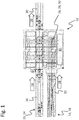
- the schematic top view of the Fig. 1 is only intended to clarify the basic structure of a packaging and / or container formation device 10 according to the invention, which serves to combine and / or repackage article groups, which is to be illustrated in the exemplary embodiment described below by transferring beverage containers into beverage crates serving as overpacks.
- These beverage crates are each suitable and provided for receiving a defined number of regularly arranged or appropriately grouped beverage containers on the top side.
- the packaging and / or container formation device 10 which is only indicated schematically here, is assigned a first conveyor section 12 for transporting a plurality of upright articles 14.
- these articles 14 are formed in particular by upright beverage containers 16, which are transported in mass flow and / or in row transport in a defined conveying direction 18, which leads to the device 10.
- the device 10 is a second conveyor line 20 located close to the first conveyor line 12 and, in the exemplary embodiment shown, running parallel to this, for the successive transport of outer packaging 22 in the form of beverage crates 24, which as outer packaging 22 each hold at least one of several articles 14 or beverage containers 16 formed article group are provided and prepared.
- the outer packaging 22 can also be formed by other boxes or crates or containers of the most varied types, for example by boxes made of simple cardboard or, for example, also by film wrappings, shrink films or other wrappings made of flat packaging material. Since the present context does not refer to a packaging device, but also to a device 10 which can be used to manufacture or form containers, i.e. From a so-called container formation device 10, strapping, film sections or other packaging materials can optionally also be brought in on the second conveyor section 20 and made available to the device 10 for further processing.
- the outer packaging 22 (or possibly the other packaging) formed by the beverage crates 24 are also moved on the second conveying path 20 in the same conveying direction 18 to the device 10 as the articles formed by the beverage container 16, for example 14 on the first conveyor section 12.
- This parallel alignment of the two conveyor sections 12 and 20 to one another is not, however, absolutely necessary, but can also vary in practice if necessary, so that optionally non-parallel conveying directions 18 of the two conveyor sections 12 and 20 for the articles 14 or Beverage containers 16 or for the outer packaging 22 or beverage crates 24 are conceivable and manageable.
- FIG. 1 A packaging and / or packaging device 10 shown in a schematic manner has a handling and / or packaging station 26 which is spatially and functionally assigned to the two conveyor sections 12 and 20.
- This handling and / or packaging station 26 is used either for packaging the one in the conveying direction 18 on the first Conveyor section 12 transported articles 14 or beverage containers 16 by transferring them into the outer packaging 22 or beverage crates 24, each of which can accommodate at least one article group or container group formed from several articles 14 or beverage containers 16.
- This packaging or transfer of the articles 14 or beverage containers 16 into the outer packaging 22 or beverage crates 24 always also includes a handling process, which is why this section of the device 10 can also be referred to as a handling and / or packaging station 26.
- the handling and / or packaging station 26 can also form the bundles by bundling the articles 14 or beverage containers 16 transported in the conveying direction 18 on the first conveyor section 12 by combining several articles 14 or beverage containers 16, e.g. serve for strapping containers, foil containers, shrink-foil containers, adhesive containers etc.
- This combination of the articles 14 or beverage containers 16 into containers also always includes a handling process.
- the handling and / or packaging station 26 is equipped with a manipulator 28, for example with at least one gripper head 30 or optionally also with a plurality of gripper heads 30 which can be controlled in parallel, which, for the simultaneous recording and detection of an article group, with each existing gripper head 30 from the The first conveyor line 12 and for transferring it to the second conveyor line 20 within the device 10 and for inserting the article group, ie the group of articles 14 or beverage containers 16, into one of the outer packaging 22 or beverage crates 24 conveyed there.
- a manipulator 28 for example with at least one gripper head 30 or optionally also with a plurality of gripper heads 30 which can be controlled in parallel, which, for the simultaneous recording and detection of an article group, with each existing gripper head 30 from the The first conveyor line 12 and for transferring it to the second conveyor line 20 within the device 10 and for inserting the article group, ie the group of articles 14 or beverage containers 16, into one of the outer packaging 22 or beverage crates 24 conveyed there.
- the manipulator 28 formed by at least one gripper head 30 or by a plurality of gripper heads 30 can also be used for this be provided to capture the articles 14 or beverage containers 16 from the first conveyor section 12 and to supply them to the further bundle formation by grouping articles 14 or containers 16 into bundles.
- the in the Fig. 1 Handling and / or packaging station 26, indicated only schematically, with manipulator 28 or with at least one gripper head 30 or with a plurality of gripper heads 30 that can be moved and controlled approximately synchronously, can be, for example, by a portal robot, a multi-axis robot, a parallel kinematics robot or another suitable one Handling device can be formed, the manipulator 28, gripper head 30 or the gripper heads 30 between the preparation station, not shown here, or the two conveyor sections 12 and 20 for transferring simultaneously several articles 14 or beverage containers 16 to the outer packaging 22 or, either ready or moving in the parallel conveying direction 18 Beverage crates 24 moved back and forth while being raised and lowered as needed.
- the controllable gripper head 30 located on a movable tool head (not shown in detail) on the manipulator 28, which is preferably used in the handling and / or packaging station 26, or the plurality of gripper heads 30 serve to hold several articles 14, beverage containers 16 or bottles at the same time.
- the gripper head 30 or the gripper heads 30 are equipped with controllable suction grippers or with controllable gripping tulips or the like, with which the articles 14, beverage containers 16 or bottles are gripped in their neck or head area and for the transfer and the approximately vertical Insert securely held in the open top packaging 22 or beverage crates 24 and can be reliably released for placement in the respective outer packaging 22 or in the beverage crate 24 provided for this purpose.
- an outer packaging 22 or a beverage crate 24 can normally be loaded with a defined number of articles 14, beverage containers 16 or bottles at the same time, For example, with a number of beverage containers 16 arranged in a rectangular combination of a total of twenty or twenty-four or more beverage containers 16 or bottles.
- the handling and / or packaging station 26 can preferably also be equipped with two or three similar gripper heads 30, which allow a correspondingly larger number of articles 14 or beverage containers 16 to be gripped simultaneously and, for example, in two or three outer packages 22 conveyed one behind the other or to drop beverage crates 24.
- the possibility created in this way of equipping several outer packaging 22 or beverage crates 24 with respective groups of articles 14 or beverage containers 16 at the same time enables a correspondingly high throughput when equipping outer packaging 22 with articles 14 or containers 16.
- the schematic representation of the Fig. 1 furthermore shows the second conveying path 20 leading out of the packaging and / or bundle forming device 10 in the conveying direction 18 to the right or continuing in the conveying direction 18, the conveying direction 18 of which for conveying away the bundles formed in the station 26 or for conveying away the articles 14
- Outer packaging 22 or the beverage crates 24 equipped with beverage containers 16 for their further handling, such as palletizing, is unchanged.
- the section of the second conveyor line 20 leading out of the device 10 to the right can form its continuation, since the beverage crates 24 do not have to be taken down or removed from the second conveyor line 20 when they are equipped with beverage containers 16.
- the reference number 32 in the Fig. 1 a direct printing and / or application station, which is located between the transport section of the first conveyor line 12 or the staging area and the handling and / or packaging station 26 and which is reached by the at least one manipulator 28 with the gripper heads 30 or the at least one gripper head 30 can be.
- This direct printing and / or application station 32 serves to apply the articles 14 or at least one of the articles 14 to at least one point on their respective outer sides with printing ink and / or a permanently adhesive coating, but can optionally be or additionally serve to attach at least one equipment element adhering to the outside of at least one article 14.
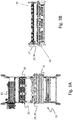
- the schematic top view of the Figure 2A shows an arrangement of the device 10 for printing on the outside of the article, in which a larger number of articles or beverage containers, not shown here, can be lifted from a first conveyor section 12 into a direct printing station 32 by means of a manipulator 28 and printed there before the articles or beverage containers are there are lifted out again in order to subsequently be inserted into outer packaging, likewise not shown here, which is conveyed on a second conveyor line 20.
- two such direct printing stations 32 can also be arranged next to one another, to which the beverage containers or articles to be printed are fed one after the other.
- the manipulator 28 can lift a defined number of articles into the first direct printing station 32a, so that the articles are printed there, in order to lift out an article which has already been printed with a second printing ink in the adjacent second printing station 32b and to the second conveyor line 20 with the to hand over the available packaging. Possibly.
- the manipulator 28 can insert previously unprinted articles into the first direct printing station 32a as soon as the latter is ready to receive the articles.
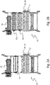
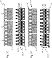
- the schematic side views of the Figures 2C to 2F illustrate a printing process of a defined number of beverage containers 16, which are fed to a direct printing station 32 by means of suitable gripper heads 30 of a manipulator 28.
- the gripper heads 30 each lift the beverage containers 16 at their neck or head regions, which can be done, for example, with suction grippers 34 with which the gripper heads 30 are equipped. It is important here that the suction grippers 34 of the gripper heads 30 can not only execute rotating movements, in order to move the beverage containers 16 by the necessary rotation movements on the fixed printing units 36 of the direct printing station 32 with the desired print images 38 (cf. Figure 2F ) to be able to provide.
- a very exact guidance of the beverage containers 16 by means of the suction pads 34 is equally important in order to avoid unclean printing due to undesired movements or insufficiently exact positioning of the beverage containers 16 on the print heads of the printing units 36.
- the Figure 2C illustrates the detection of article groups of four beverage containers 16 each on a gripper head 30 which is equipped with a total of four rotatable suction pads 34.
- a total of three gripper heads 30 are located on a common manipulator 28 which can be raised and lowered and which conveys the beverage containers 16 from the first conveyor line (not shown here) to the direct printing station 32 and after printing from this to the second conveyor line (also not shown here) ) can be transported with the outer packaging or optionally to a container formation station.
- the total of twelve beverage containers 16 shown here using the example shown are lifted together by lowering the manipulator 28 into the direct printing station 32 in order to be fed there to the printing units 36.
- a plurality of printing units 36 can be located one above the other, to which the beverage containers 16 are guided one after the other by vertical movements of the manipulator 28 with the gripper heads 30 and, if necessary, rotated in order to successively apply different printing inks to the lateral surfaces of the beverage containers 16 in a direct printing process.
- the direct printing station 32 can have a first printing unit 36a for a first printing ink, a second printing unit 36b for a second printing ink and a third printing unit 36c for a third printing ink, which are each arranged one above the other, so that the beverage containers 16 are only connected by means of the gripper heads 30 adjusted in height, but do not have to be moved or moved between several printing stations 32.
- the Figure 2D shows the beverage containers 16 brought into the area of the upper two printing units 36a and 36b, while the Figure 2E shows the beverage container 16, which has been lowered even further, the outer sides of which are to be printed are brought into the printing range of the third printing unit 36c, so that they are printed there completely.
- the Figure 2F illustrates the beverage containers 16, which are lifted out of the direct printing station 32 with the manipulator 28 raised, to the outer lateral surfaces of which a printed image 38 was applied in each case by the direct printing method.
- the schematic top view of the Figure 3A shows an alternative arrangement of the device 10 for printing on the outside of the article, in which a larger number of articles or beverage containers (not shown here) are moved from a first conveyor section 12 into a direct printing station 32 by means of a manipulator 28 can be lifted in and printed there before the articles or beverage containers are lifted out again, in order then to be inserted into overpacks, likewise not shown here, which are conveyed on a second conveyor line 20.
- the turntable 40 is assigned to the direct printing station 32, onto which the articles or beverage containers are respectively placed and held during printing in order to be able to move them past the print heads of the direct printing station 32 in a rotating movement.
- the printing units 36 of the direct printing station 32 can be designed to be height-adjustable in this variant, in order not to have to adjust the height of the turntables 40.
- a plurality of printing units 36 can also be arranged one above the other, which can be activated after corresponding vertical movements and can be used for the successive application of different printing inks to the lateral surfaces of the articles 14 or beverage containers 16 to be printed.
- the manipulator 28 can, for example, lift a defined number of articles into the direct printing station 32 and place them on the turntables 40 located there, so that the articles are printed there, in order then to lift the finished printed articles out and to the second conveyor path 20 with the available packaging.
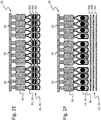
- FIG. 3C The schematic side views of the Figures 3C to 3F illustrate a printing process of a defined number of beverage containers 16, which are fed to a direct printing station 32 with turntables 40 by means of suitable gripper heads 30 of a manipulator 28.
- the gripper heads 30 each lift the beverage containers 16 at their neck or head areas, for example with suction grippers 34 (cf. Figure 3C ).
- the gripper heads 30 with the suction pads 34 are only responsible for the transfer movement, but not for the exact positioning of the beverage containers 16 on the print heads 36. This takes place in the interaction of the height-adjustable printing units 36 and the rotating turntables 40 on which the printable items are to be printed Beverage containers 16 are fixed.
- the turntables 40 can be rotated so that the beverage containers 16 can be rotated, if necessary, by rotating the turntables 40 on the height-adjustable printing units 36 of the direct printing station 32 with the desired print images 38 (cf. Figure 2F ) can be provided.
- the direct printing station 32 can have a first printing unit 36a for a first printing ink, a second printing unit 36b for a second printing ink and a third printing unit 36c for a third printing ink, which are respectively arranged one above the other and can be adjusted in height (cf. Figure 3F ), so that the beverage containers 16 do not have to be moved or moved between a plurality of printing stations 32.
- FIG. 1 to 3F The schematic views of the Figures 1 to 3F illustrate the peculiarities and new aspects that characterize the method according to the invention, in that a plurality of articles 14 or beverage containers 16 captured by the manipulator 28 are passed on to a packaging and / or container formation station arranged downstream of the transport route or before being inserted into outer packaging 22 or beverage crates 24 provided for this purpose printing ink and / or a permanently adhering coating are applied to at least one point of their respective outer sides and / or at least one equipment element (not shown here) adhering to the outside of at least one article 14.
- the high control and positioning accuracies of the available manipulators 28 are used in particular, since these manipulators 28 are not only able to transfer the received articles 14 with high precision into available outer packaging 22 or a packaging and / or or container formation station 10 in compliance with tight spatial tolerances.
- the positioning performance achievable with the manipulators 28 are used in the present application to move the articles 14 transferred to a destination on their way past the printing and / or application devices prepared for this purpose, so that they have a coating, a printing and / or a other equipment can be provided. This means that, depending on requirements, approximately 14 printed images 38, bar codes, spray labels, individual labels, so-called tracking IDs, RFIDs or the like can be applied to the articles 14.
Landscapes
- Engineering & Computer Science (AREA)
- Mechanical Engineering (AREA)
- Manufacturing & Machinery (AREA)
- Auxiliary Devices For And Details Of Packaging Control (AREA)
Applications Claiming Priority (1)
| Application Number | Priority Date | Filing Date | Title |
|---|---|---|---|
| DE102018131988.6A DE102018131988A1 (de) | 2018-12-12 | 2018-12-12 | Vorrichtung und Verfahren zur Handhabung und/oder zum Verpacken von Artikeln |
Publications (3)
| Publication Number | Publication Date |
|---|---|
| EP3689761A2 true EP3689761A2 (fr) | 2020-08-05 |
| EP3689761A3 EP3689761A3 (fr) | 2020-10-21 |
| EP3689761B1 EP3689761B1 (fr) | 2023-09-13 |
Family
ID=68470399
Family Applications (1)
| Application Number | Title | Priority Date | Filing Date |
|---|---|---|---|
| EP19207468.0A Active EP3689761B1 (fr) | 2018-12-12 | 2019-11-06 | Dispositif et procédé de manipulation et / ou d'emballage d'articles |
Country Status (3)
| Country | Link |
|---|---|
| EP (1) | EP3689761B1 (fr) |
| CN (1) | CN211281763U (fr) |
| DE (1) | DE102018131988A1 (fr) |
Families Citing this family (1)
| Publication number | Priority date | Publication date | Assignee | Title |
|---|---|---|---|---|
| WO2025121143A1 (fr) * | 2023-12-08 | 2025-06-12 | 株式会社ナベル | Appareil de traitement de boîtier |
Citations (5)
| Publication number | Priority date | Publication date | Assignee | Title |
|---|---|---|---|---|
| DE102014218361A1 (de) | 2014-09-12 | 2016-03-17 | Krones Ag | Vorrichtung und Verfahren zum Behandeln von Behältern durch Direktdruck und/oderEtikettierung |
| WO2017032553A1 (fr) | 2015-08-21 | 2017-03-02 | Krones Ag | Machine d'impression directe et procédé pour effectuer une impression directe sur des contenants |
| WO2017084804A1 (fr) | 2015-11-20 | 2017-05-26 | Krones Ag | Machine d'impression directe et procédé pour effectuer une impression directe sur des contenants |
| WO2018108361A1 (fr) | 2016-12-16 | 2018-06-21 | Krones Ag | Procédé et machine d'impression directe pour effectuer une impression directe sur des contenants circulaires |
| WO2018114097A1 (fr) | 2016-12-23 | 2018-06-28 | Krones Ag | Procédé et machine d'impression directe pour imprimer sur des récipients en différents types de matériau en impression directement |
Family Cites Families (4)
| Publication number | Priority date | Publication date | Assignee | Title |
|---|---|---|---|---|
| JP2000313522A (ja) * | 1999-04-28 | 2000-11-14 | Yokohama Rubber Co Ltd:The | 梱包箱の搬送方法及びその装置 |
| US8454067B2 (en) * | 2010-10-28 | 2013-06-04 | Standard Knapp Inc. | Adjustable gripper head assembly |
| EP2450283B1 (fr) * | 2010-11-04 | 2014-12-17 | Müller Martini Holding AG | Procédé de caractérisation d'un fût constitué d'un produit d'impression et dispositif d'exécution du procédé |
| DE102011119966B3 (de) * | 2011-12-02 | 2012-11-22 | Khs Gmbh | Vorrichtung zur Bildung von Verpackungseinheiten |
-
2018
- 2018-12-12 DE DE102018131988.6A patent/DE102018131988A1/de not_active Withdrawn
-
2019
- 2019-11-06 EP EP19207468.0A patent/EP3689761B1/fr active Active
- 2019-11-28 CN CN201922113361.8U patent/CN211281763U/zh active Active
Patent Citations (5)
| Publication number | Priority date | Publication date | Assignee | Title |
|---|---|---|---|---|
| DE102014218361A1 (de) | 2014-09-12 | 2016-03-17 | Krones Ag | Vorrichtung und Verfahren zum Behandeln von Behältern durch Direktdruck und/oderEtikettierung |
| WO2017032553A1 (fr) | 2015-08-21 | 2017-03-02 | Krones Ag | Machine d'impression directe et procédé pour effectuer une impression directe sur des contenants |
| WO2017084804A1 (fr) | 2015-11-20 | 2017-05-26 | Krones Ag | Machine d'impression directe et procédé pour effectuer une impression directe sur des contenants |
| WO2018108361A1 (fr) | 2016-12-16 | 2018-06-21 | Krones Ag | Procédé et machine d'impression directe pour effectuer une impression directe sur des contenants circulaires |
| WO2018114097A1 (fr) | 2016-12-23 | 2018-06-28 | Krones Ag | Procédé et machine d'impression directe pour imprimer sur des récipients en différents types de matériau en impression directement |
Also Published As
| Publication number | Publication date |
|---|---|
| CN211281763U (zh) | 2020-08-18 |
| EP3689761B1 (fr) | 2023-09-13 |
| EP3689761A3 (fr) | 2020-10-21 |
| DE102018131988A1 (de) | 2020-06-18 |
Similar Documents
| Publication | Publication Date | Title |
|---|---|---|
| EP3012198B9 (fr) | Dispositif et procede de manutention d'articles | |
| WO2020233943A1 (fr) | Dispositif d'emballage et procédé de fabrication d'unités d'emballage | |
| DE102013113754A1 (de) | Verfahren zur Bildung von Gebinden und zu deren Palettierung sowie Förder- und Handhabungsvorrichtung für Artikel und Gebinde | |
| DE102010016056A1 (de) | Verfahren zum Drehen lose gruppierter Artikel | |
| WO2020052889A1 (fr) | Dispositif d'emballage et procédé d'emballage d'articles | |
| EP4132852A1 (fr) | Dispositif et procédé d'emballage pour emballer des articles | |
| EP3549877B1 (fr) | Dispositif d'emballage et procédé de transformation et / ou d'équipement d'un dispositif d'emballage | |
| EP3652093A1 (fr) | Procédé et dispositif pour manipuler des marchandises, articles et/ou paquets | |
| DE102017118928A1 (de) | Lagenbildungs- und Palettiermodul und Verfahren zum Gruppieren und Palettieren von Stückgütern | |
| EP4186829B1 (fr) | Dispositif de préhension et procédé de manipulation de marchandises de détail | |
| EP3689761B1 (fr) | Dispositif et procédé de manipulation et / ou d'emballage d'articles | |
| EP3652094B1 (fr) | Procédé et appareil pour la manutention de marchandises, d'articles et/ou d'emballages | |
| DE10115543A1 (de) | Verfahren und Vorrichtung zum Verpacken von Behältern | |
| EP3623323A1 (fr) | Procédé et dispositif de manipulation des marchandises, des articles et / ou des emballages | |
| EP4452761A1 (fr) | Dispositif d'emballage et procédé d'emballage pour transférer des articles dans des suremballages | |
| WO2018010953A1 (fr) | Procédé et dispositif d'étiquetage de premiers emballages | |
| EP2848416B1 (fr) | Transport de matériau d'emballage et dispositif de traitement de matériaux d'emballage doté d'un tel système de transport | |
| DE102024113655A1 (de) | Fördervorrichtung und Verfahren zum Behältertransport sowie System zur Förderung und Verpackung von Behältern | |
| EP4556414A1 (fr) | Dispositif et procédé pour emballer et former des couches d'unités d'emballage | |
| DE102020132284A1 (de) | Verpackungsanlage und Verfahren zum Herstellen von Verpackungseinheiten | |
| WO2025119601A1 (fr) | Appareil d'emballage, et procédé pour emballer des articles | |
| DE102023127806A1 (de) | Verpackungsvorrichtung und Verfahren zur Herstellung von Verpackungseinheiten | |
| DE102023128375A1 (de) | Verpackungsmaschine und Verfahren zur Funktionsüberwachung von Handhabungseinrichtungen innerhalb von Verpackungsprozessen | |
| DE102024123454A1 (de) | Vorrichtung und Verfahren zur Herstellung von Klebegebinden | |
| DE102024113654A1 (de) | Verpackungssystem mit mindestens einer Weiche und Verfahren zum Verpacken von Artikeln |
Legal Events
| Date | Code | Title | Description |
|---|---|---|---|
| PUAI | Public reference made under article 153(3) epc to a published international application that has entered the european phase |
Free format text: ORIGINAL CODE: 0009012 |
|
| STAA | Information on the status of an ep patent application or granted ep patent |
Free format text: STATUS: THE APPLICATION HAS BEEN PUBLISHED |
|
| AK | Designated contracting states |
Kind code of ref document: A2 Designated state(s): AL AT BE BG CH CY CZ DE DK EE ES FI FR GB GR HR HU IE IS IT LI LT LU LV MC MK MT NL NO PL PT RO RS SE SI SK SM TR |
|
| AX | Request for extension of the european patent |
Extension state: BA ME |
|
| PUAL | Search report despatched |
Free format text: ORIGINAL CODE: 0009013 |
|
| AK | Designated contracting states |
Kind code of ref document: A3 Designated state(s): AL AT BE BG CH CY CZ DE DK EE ES FI FR GB GR HR HU IE IS IT LI LT LU LV MC MK MT NL NO PL PT RO RS SE SI SK SM TR |
|
| AX | Request for extension of the european patent |
Extension state: BA ME |
|
| RIC1 | Information provided on ipc code assigned before grant |
Ipc: B65B 35/36 20060101ALI20200915BHEP Ipc: B65B 61/02 20060101ALI20200915BHEP Ipc: B41J 3/407 20060101ALI20200915BHEP Ipc: B65B 21/06 20060101AFI20200915BHEP Ipc: B65B 61/26 20060101ALI20200915BHEP Ipc: B65C 9/06 20060101ALI20200915BHEP Ipc: B65B 61/14 20060101ALI20200915BHEP Ipc: B65C 9/04 20060101ALI20200915BHEP Ipc: B65B 21/18 20060101ALI20200915BHEP Ipc: B65B 61/20 20060101ALI20200915BHEP |
|
| STAA | Information on the status of an ep patent application or granted ep patent |
Free format text: STATUS: REQUEST FOR EXAMINATION WAS MADE |
|
| 17P | Request for examination filed |
Effective date: 20210407 |
|
| RBV | Designated contracting states (corrected) |
Designated state(s): AL AT BE BG CH CY CZ DE DK EE ES FI FR GB GR HR HU IE IS IT LI LT LU LV MC MK MT NL NO PL PT RO RS SE SI SK SM TR |
|
| STAA | Information on the status of an ep patent application or granted ep patent |
Free format text: STATUS: EXAMINATION IS IN PROGRESS |
|
| 17Q | First examination report despatched |
Effective date: 20210727 |
|
| GRAP | Despatch of communication of intention to grant a patent |
Free format text: ORIGINAL CODE: EPIDOSNIGR1 |
|
| STAA | Information on the status of an ep patent application or granted ep patent |
Free format text: STATUS: GRANT OF PATENT IS INTENDED |
|
| INTG | Intention to grant announced |
Effective date: 20230406 |
|
| P01 | Opt-out of the competence of the unified patent court (upc) registered |
Effective date: 20230523 |
|
| GRAS | Grant fee paid |
Free format text: ORIGINAL CODE: EPIDOSNIGR3 |
|
| GRAA | (expected) grant |
Free format text: ORIGINAL CODE: 0009210 |
|
| STAA | Information on the status of an ep patent application or granted ep patent |
Free format text: STATUS: THE PATENT HAS BEEN GRANTED |
|
| AK | Designated contracting states |
Kind code of ref document: B1 Designated state(s): AL AT BE BG CH CY CZ DE DK EE ES FI FR GB GR HR HU IE IS IT LI LT LU LV MC MK MT NL NO PL PT RO RS SE SI SK SM TR |
|
| REG | Reference to a national code |
Ref country code: CH Ref legal event code: EP |
|
| REG | Reference to a national code |
Ref country code: DE Ref legal event code: R096 Ref document number: 502019009325 Country of ref document: DE |
|
| REG | Reference to a national code |
Ref country code: IE Ref legal event code: FG4D Free format text: LANGUAGE OF EP DOCUMENT: GERMAN |
|
| REG | Reference to a national code |
Ref country code: LT Ref legal event code: MG9D |
|
| REG | Reference to a national code |
Ref country code: NL Ref legal event code: MP Effective date: 20230913 |
|
| PG25 | Lapsed in a contracting state [announced via postgrant information from national office to epo] |
Ref country code: GR Free format text: LAPSE BECAUSE OF FAILURE TO SUBMIT A TRANSLATION OF THE DESCRIPTION OR TO PAY THE FEE WITHIN THE PRESCRIBED TIME-LIMIT Effective date: 20231214 |
|
| PG25 | Lapsed in a contracting state [announced via postgrant information from national office to epo] |
Ref country code: SE Free format text: LAPSE BECAUSE OF FAILURE TO SUBMIT A TRANSLATION OF THE DESCRIPTION OR TO PAY THE FEE WITHIN THE PRESCRIBED TIME-LIMIT Effective date: 20230913 Ref country code: RS Free format text: LAPSE BECAUSE OF FAILURE TO SUBMIT A TRANSLATION OF THE DESCRIPTION OR TO PAY THE FEE WITHIN THE PRESCRIBED TIME-LIMIT Effective date: 20230913 Ref country code: NO Free format text: LAPSE BECAUSE OF FAILURE TO SUBMIT A TRANSLATION OF THE DESCRIPTION OR TO PAY THE FEE WITHIN THE PRESCRIBED TIME-LIMIT Effective date: 20231213 Ref country code: LV Free format text: LAPSE BECAUSE OF FAILURE TO SUBMIT A TRANSLATION OF THE DESCRIPTION OR TO PAY THE FEE WITHIN THE PRESCRIBED TIME-LIMIT Effective date: 20230913 Ref country code: LT Free format text: LAPSE BECAUSE OF FAILURE TO SUBMIT A TRANSLATION OF THE DESCRIPTION OR TO PAY THE FEE WITHIN THE PRESCRIBED TIME-LIMIT Effective date: 20230913 Ref country code: HR Free format text: LAPSE BECAUSE OF FAILURE TO SUBMIT A TRANSLATION OF THE DESCRIPTION OR TO PAY THE FEE WITHIN THE PRESCRIBED TIME-LIMIT Effective date: 20230913 Ref country code: GR Free format text: LAPSE BECAUSE OF FAILURE TO SUBMIT A TRANSLATION OF THE DESCRIPTION OR TO PAY THE FEE WITHIN THE PRESCRIBED TIME-LIMIT Effective date: 20231214 Ref country code: FI Free format text: LAPSE BECAUSE OF FAILURE TO SUBMIT A TRANSLATION OF THE DESCRIPTION OR TO PAY THE FEE WITHIN THE PRESCRIBED TIME-LIMIT Effective date: 20230913 |
|
| PG25 | Lapsed in a contracting state [announced via postgrant information from national office to epo] |
Ref country code: NL Free format text: LAPSE BECAUSE OF FAILURE TO SUBMIT A TRANSLATION OF THE DESCRIPTION OR TO PAY THE FEE WITHIN THE PRESCRIBED TIME-LIMIT Effective date: 20230913 |
|
| PG25 | Lapsed in a contracting state [announced via postgrant information from national office to epo] |
Ref country code: IS Free format text: LAPSE BECAUSE OF FAILURE TO SUBMIT A TRANSLATION OF THE DESCRIPTION OR TO PAY THE FEE WITHIN THE PRESCRIBED TIME-LIMIT Effective date: 20240113 |
|
| PG25 | Lapsed in a contracting state [announced via postgrant information from national office to epo] |
Ref country code: ES Free format text: LAPSE BECAUSE OF FAILURE TO SUBMIT A TRANSLATION OF THE DESCRIPTION OR TO PAY THE FEE WITHIN THE PRESCRIBED TIME-LIMIT Effective date: 20230913 |
|
| PG25 | Lapsed in a contracting state [announced via postgrant information from national office to epo] |
Ref country code: SM Free format text: LAPSE BECAUSE OF FAILURE TO SUBMIT A TRANSLATION OF THE DESCRIPTION OR TO PAY THE FEE WITHIN THE PRESCRIBED TIME-LIMIT Effective date: 20230913 Ref country code: RO Free format text: LAPSE BECAUSE OF FAILURE TO SUBMIT A TRANSLATION OF THE DESCRIPTION OR TO PAY THE FEE WITHIN THE PRESCRIBED TIME-LIMIT Effective date: 20230913 Ref country code: IS Free format text: LAPSE BECAUSE OF FAILURE TO SUBMIT A TRANSLATION OF THE DESCRIPTION OR TO PAY THE FEE WITHIN THE PRESCRIBED TIME-LIMIT Effective date: 20240113 Ref country code: ES Free format text: LAPSE BECAUSE OF FAILURE TO SUBMIT A TRANSLATION OF THE DESCRIPTION OR TO PAY THE FEE WITHIN THE PRESCRIBED TIME-LIMIT Effective date: 20230913 Ref country code: EE Free format text: LAPSE BECAUSE OF FAILURE TO SUBMIT A TRANSLATION OF THE DESCRIPTION OR TO PAY THE FEE WITHIN THE PRESCRIBED TIME-LIMIT Effective date: 20230913 Ref country code: CZ Free format text: LAPSE BECAUSE OF FAILURE TO SUBMIT A TRANSLATION OF THE DESCRIPTION OR TO PAY THE FEE WITHIN THE PRESCRIBED TIME-LIMIT Effective date: 20230913 Ref country code: SK Free format text: LAPSE BECAUSE OF FAILURE TO SUBMIT A TRANSLATION OF THE DESCRIPTION OR TO PAY THE FEE WITHIN THE PRESCRIBED TIME-LIMIT Effective date: 20230913 Ref country code: PT Free format text: LAPSE BECAUSE OF FAILURE TO SUBMIT A TRANSLATION OF THE DESCRIPTION OR TO PAY THE FEE WITHIN THE PRESCRIBED TIME-LIMIT Effective date: 20240115 |
|
| PG25 | Lapsed in a contracting state [announced via postgrant information from national office to epo] |
Ref country code: PL Free format text: LAPSE BECAUSE OF FAILURE TO SUBMIT A TRANSLATION OF THE DESCRIPTION OR TO PAY THE FEE WITHIN THE PRESCRIBED TIME-LIMIT Effective date: 20230913 |
|
| REG | Reference to a national code |
Ref country code: DE Ref legal event code: R097 Ref document number: 502019009325 Country of ref document: DE |
|
| REG | Reference to a national code |
Ref country code: CH Ref legal event code: PL |
|
| PG25 | Lapsed in a contracting state [announced via postgrant information from national office to epo] |
Ref country code: MC Free format text: LAPSE BECAUSE OF FAILURE TO SUBMIT A TRANSLATION OF THE DESCRIPTION OR TO PAY THE FEE WITHIN THE PRESCRIBED TIME-LIMIT Effective date: 20230913 |
|
| PG25 | Lapsed in a contracting state [announced via postgrant information from national office to epo] |
Ref country code: DK Free format text: LAPSE BECAUSE OF FAILURE TO SUBMIT A TRANSLATION OF THE DESCRIPTION OR TO PAY THE FEE WITHIN THE PRESCRIBED TIME-LIMIT Effective date: 20230913 |
|
| PG25 | Lapsed in a contracting state [announced via postgrant information from national office to epo] |
Ref country code: LU Free format text: LAPSE BECAUSE OF NON-PAYMENT OF DUE FEES Effective date: 20231106 |
|
| PG25 | Lapsed in a contracting state [announced via postgrant information from national office to epo] |
Ref country code: CH Free format text: LAPSE BECAUSE OF NON-PAYMENT OF DUE FEES Effective date: 20231130 |
|
| PLBE | No opposition filed within time limit |
Free format text: ORIGINAL CODE: 0009261 |
|
| STAA | Information on the status of an ep patent application or granted ep patent |
Free format text: STATUS: NO OPPOSITION FILED WITHIN TIME LIMIT |
|
| PG25 | Lapsed in a contracting state [announced via postgrant information from national office to epo] |
Ref country code: MC Free format text: LAPSE BECAUSE OF FAILURE TO SUBMIT A TRANSLATION OF THE DESCRIPTION OR TO PAY THE FEE WITHIN THE PRESCRIBED TIME-LIMIT Effective date: 20230913 Ref country code: LU Free format text: LAPSE BECAUSE OF NON-PAYMENT OF DUE FEES Effective date: 20231106 Ref country code: DK Free format text: LAPSE BECAUSE OF FAILURE TO SUBMIT A TRANSLATION OF THE DESCRIPTION OR TO PAY THE FEE WITHIN THE PRESCRIBED TIME-LIMIT Effective date: 20230913 Ref country code: CH Free format text: LAPSE BECAUSE OF NON-PAYMENT OF DUE FEES Effective date: 20231130 |
|
| REG | Reference to a national code |
Ref country code: BE Ref legal event code: MM Effective date: 20231130 |
|
| 26N | No opposition filed |
Effective date: 20240614 |
|
| GBPC | Gb: european patent ceased through non-payment of renewal fee |
Effective date: 20231213 |
|
| REG | Reference to a national code |
Ref country code: IE Ref legal event code: MM4A |
|
| PG25 | Lapsed in a contracting state [announced via postgrant information from national office to epo] |
Ref country code: IE Free format text: LAPSE BECAUSE OF NON-PAYMENT OF DUE FEES Effective date: 20231106 |
|
| PG25 | Lapsed in a contracting state [announced via postgrant information from national office to epo] |
Ref country code: GB Free format text: LAPSE BECAUSE OF NON-PAYMENT OF DUE FEES Effective date: 20231213 |
|
| PG25 | Lapsed in a contracting state [announced via postgrant information from national office to epo] |
Ref country code: BE Free format text: LAPSE BECAUSE OF NON-PAYMENT OF DUE FEES Effective date: 20231130 |
|
| PG25 | Lapsed in a contracting state [announced via postgrant information from national office to epo] |
Ref country code: SI Free format text: LAPSE BECAUSE OF FAILURE TO SUBMIT A TRANSLATION OF THE DESCRIPTION OR TO PAY THE FEE WITHIN THE PRESCRIBED TIME-LIMIT Effective date: 20230913 |
|
| PG25 | Lapsed in a contracting state [announced via postgrant information from national office to epo] |
Ref country code: SI Free format text: LAPSE BECAUSE OF FAILURE TO SUBMIT A TRANSLATION OF THE DESCRIPTION OR TO PAY THE FEE WITHIN THE PRESCRIBED TIME-LIMIT Effective date: 20230913 Ref country code: IE Free format text: LAPSE BECAUSE OF NON-PAYMENT OF DUE FEES Effective date: 20231106 Ref country code: GB Free format text: LAPSE BECAUSE OF NON-PAYMENT OF DUE FEES Effective date: 20231213 Ref country code: BE Free format text: LAPSE BECAUSE OF NON-PAYMENT OF DUE FEES Effective date: 20231130 |
|
| REG | Reference to a national code |
Ref country code: DE Ref legal event code: R082 Ref document number: 502019009325 Country of ref document: DE Representative=s name: BENNINGER, JOHANNES, DIPL.-ING., DE |
|
| PG25 | Lapsed in a contracting state [announced via postgrant information from national office to epo] |
Ref country code: BG Free format text: LAPSE BECAUSE OF FAILURE TO SUBMIT A TRANSLATION OF THE DESCRIPTION OR TO PAY THE FEE WITHIN THE PRESCRIBED TIME-LIMIT Effective date: 20230913 |
|
| PG25 | Lapsed in a contracting state [announced via postgrant information from national office to epo] |
Ref country code: BG Free format text: LAPSE BECAUSE OF FAILURE TO SUBMIT A TRANSLATION OF THE DESCRIPTION OR TO PAY THE FEE WITHIN THE PRESCRIBED TIME-LIMIT Effective date: 20230913 |
|
| PGFP | Annual fee paid to national office [announced via postgrant information from national office to epo] |
Ref country code: DE Payment date: 20241001 Year of fee payment: 6 |
|
| PGFP | Annual fee paid to national office [announced via postgrant information from national office to epo] |
Ref country code: FR Payment date: 20241001 Year of fee payment: 6 |
|
| PGFP | Annual fee paid to national office [announced via postgrant information from national office to epo] |
Ref country code: IT Payment date: 20241010 Year of fee payment: 6 |
|
| PG25 | Lapsed in a contracting state [announced via postgrant information from national office to epo] |
Ref country code: CY Free format text: LAPSE BECAUSE OF FAILURE TO SUBMIT A TRANSLATION OF THE DESCRIPTION OR TO PAY THE FEE WITHIN THE PRESCRIBED TIME-LIMIT; INVALID AB INITIO Effective date: 20191106 |
|
| PG25 | Lapsed in a contracting state [announced via postgrant information from national office to epo] |
Ref country code: HU Free format text: LAPSE BECAUSE OF FAILURE TO SUBMIT A TRANSLATION OF THE DESCRIPTION OR TO PAY THE FEE WITHIN THE PRESCRIBED TIME-LIMIT; INVALID AB INITIO Effective date: 20191106 |
|
| PG25 | Lapsed in a contracting state [announced via postgrant information from national office to epo] |
Ref country code: TR Free format text: LAPSE BECAUSE OF FAILURE TO SUBMIT A TRANSLATION OF THE DESCRIPTION OR TO PAY THE FEE WITHIN THE PRESCRIBED TIME-LIMIT Effective date: 20230913 |
|
| PG25 | Lapsed in a contracting state [announced via postgrant information from national office to epo] |
Ref country code: AT Free format text: LAPSE BECAUSE OF NON-PAYMENT OF DUE FEES Effective date: 20241106 |
|
| REG | Reference to a national code |
Ref country code: AT Ref legal event code: MM01 Ref document number: 1611067 Country of ref document: AT Kind code of ref document: T Effective date: 20241106 |
|
| PGFP | Annual fee paid to national office [announced via postgrant information from national office to epo] |
Ref country code: AT Payment date: 20260410 Year of fee payment: 5 |