EP3693140B1 - Verfahren zur schätzung der position, an der eine anomalie erzeugt wurde, und programm zur ausführung der schätzung der position, an der eine anomalie erzeugt wurde - Google Patents
Verfahren zur schätzung der position, an der eine anomalie erzeugt wurde, und programm zur ausführung der schätzung der position, an der eine anomalie erzeugt wurde Download PDFInfo
- Publication number
- EP3693140B1 EP3693140B1 EP18864190.6A EP18864190A EP3693140B1 EP 3693140 B1 EP3693140 B1 EP 3693140B1 EP 18864190 A EP18864190 A EP 18864190A EP 3693140 B1 EP3693140 B1 EP 3693140B1
- Authority
- EP
- European Patent Office
- Prior art keywords
- abnormality
- value
- waveform
- servo motor
- occurred
- Prior art date
- Legal status (The legal status is an assumption and is not a legal conclusion. Google has not performed a legal analysis and makes no representation as to the accuracy of the status listed.)
- Active
Links
Images




Classifications
-
- B—PERFORMING OPERATIONS; TRANSPORTING
- B25—HAND TOOLS; PORTABLE POWER-DRIVEN TOOLS; MANIPULATORS
- B25J—MANIPULATORS; CHAMBERS PROVIDED WITH MANIPULATION DEVICES
- B25J19/00—Accessories fitted to manipulators, e.g. for monitoring, for viewing; Safety devices combined with or specially adapted for use in connection with manipulators
- B25J19/06—Safety devices
-
- B—PERFORMING OPERATIONS; TRANSPORTING
- B25—HAND TOOLS; PORTABLE POWER-DRIVEN TOOLS; MANIPULATORS
- B25J—MANIPULATORS; CHAMBERS PROVIDED WITH MANIPULATION DEVICES
- B25J9/00—Program-controlled manipulators
- B25J9/10—Program-controlled manipulators characterised by positioning means for manipulator elements
- B25J9/12—Program-controlled manipulators characterised by positioning means for manipulator elements electric
-
- B—PERFORMING OPERATIONS; TRANSPORTING
- B25—HAND TOOLS; PORTABLE POWER-DRIVEN TOOLS; MANIPULATORS
- B25J—MANIPULATORS; CHAMBERS PROVIDED WITH MANIPULATION DEVICES
- B25J9/00—Program-controlled manipulators
- B25J9/10—Program-controlled manipulators characterised by positioning means for manipulator elements
- B25J9/12—Program-controlled manipulators characterised by positioning means for manipulator elements electric
- B25J9/126—Rotary actuators
-
- B—PERFORMING OPERATIONS; TRANSPORTING
- B25—HAND TOOLS; PORTABLE POWER-DRIVEN TOOLS; MANIPULATORS
- B25J—MANIPULATORS; CHAMBERS PROVIDED WITH MANIPULATION DEVICES
- B25J9/00—Program-controlled manipulators
- B25J9/16—Program controls
- B25J9/1674—Program controls characterised by safety, monitoring, diagnostic
-
- G—PHYSICS
- G05—CONTROLLING; REGULATING
- G05B—CONTROL OR REGULATING SYSTEMS IN GENERAL; FUNCTIONAL ELEMENTS OF SUCH SYSTEMS; MONITORING OR TESTING ARRANGEMENTS FOR SUCH SYSTEMS OR ELEMENTS
- G05B23/00—Testing or monitoring of control systems or parts thereof
- G05B23/02—Electric testing or monitoring
-
- B—PERFORMING OPERATIONS; TRANSPORTING
- B25—HAND TOOLS; PORTABLE POWER-DRIVEN TOOLS; MANIPULATORS
- B25J—MANIPULATORS; CHAMBERS PROVIDED WITH MANIPULATION DEVICES
- B25J9/00—Program-controlled manipulators
- B25J9/16—Program controls
- B25J9/1628—Program controls characterised by the control loop
- B25J9/1653—Program controls characterised by the control loop parameters identification, estimation, stiffness, accuracy, error analysis
-
- G—PHYSICS
- G05—CONTROLLING; REGULATING
- G05B—CONTROL OR REGULATING SYSTEMS IN GENERAL; FUNCTIONAL ELEMENTS OF SUCH SYSTEMS; MONITORING OR TESTING ARRANGEMENTS FOR SUCH SYSTEMS OR ELEMENTS
- G05B2219/00—Program-control systems
- G05B2219/30—Nc systems
- G05B2219/37—Measurements
- G05B2219/37525—Mean, average values, statistical derived values
-
- G—PHYSICS
- G05—CONTROLLING; REGULATING
- G05B—CONTROL OR REGULATING SYSTEMS IN GENERAL; FUNCTIONAL ELEMENTS OF SUCH SYSTEMS; MONITORING OR TESTING ARRANGEMENTS FOR SUCH SYSTEMS OR ELEMENTS
- G05B2219/00—Program-control systems
- G05B2219/30—Nc systems
- G05B2219/42—Servomotor, servo controller kind till VSS
- G05B2219/42319—What kind of actuator failure
-
- G—PHYSICS
- G05—CONTROLLING; REGULATING
- G05B—CONTROL OR REGULATING SYSTEMS IN GENERAL; FUNCTIONAL ELEMENTS OF SUCH SYSTEMS; MONITORING OR TESTING ARRANGEMENTS FOR SUCH SYSTEMS OR ELEMENTS
- G05B2219/00—Program-control systems
- G05B2219/30—Nc systems
- G05B2219/42—Servomotor, servo controller kind till VSS
- G05B2219/42323—Detect wire break, short circuit of feedback
-
- G—PHYSICS
- G05—CONTROLLING; REGULATING
- G05B—CONTROL OR REGULATING SYSTEMS IN GENERAL; FUNCTIONAL ELEMENTS OF SUCH SYSTEMS; MONITORING OR TESTING ARRANGEMENTS FOR SUCH SYSTEMS OR ELEMENTS
- G05B2219/00—Program-control systems
- G05B2219/30—Nc systems
- G05B2219/50—Machine tool, machine tool null till machine tool work handling
- G05B2219/50197—Signature analysis, store working conditions, compare with actual
Definitions
- PTL 1 discloses a conventional technique of monitoring a value of a current flowing through a servo motor and a deviation amount of the servo motor in order to detect an abnormality due to deterioration over time in a robot.
- PTL 1 discloses that the value of the current flowing through the servo motor and the deviation amount of the servo motor are used as deterioration indication parameters, and that when these deterioration indication parameters exceed a threshold, a device is stopped and an alarm is issued.
- a method for estimating a position where an abnormality has occurred is a method for estimating a position where an abnormality has occurred in a robot that drives an arm using a servo motor, the method including an abnormality detection step of detecting that an abnormality has occurred, a position detection step of detecting, when occurrence of the abnormality is detected in the abnormality detection step, a position the abnormality has occurred, a cycle observed value detection step of observing a transition of a value of a current flowing through the servo motor or a position deviation of the servo motor as an observed value, and detecting a representative value of the observed value for each cycle in a prescribed operation of an operation for each cycle in an operation repeatedly performed by the robot; and a daily observed value detection step of detecting a representative value of the observed value for each day from the representative value of the observed value detected for each cycle.
- One mean square value and one peak value are calculated for one cycle, and these values are stored as representative values for each cycle.
- the median and the standard deviation of the peak value are calculated for each day, the median and the standard deviation can be represented in a graph. Therefore, by drawing an extension of the data on the median and the standard deviation on the graph, a daily change in the median and the standard deviation is predicted using an approximate curve (S402). This makes it possible to read a daily trend of the peak value of the current value.
- the processing proceeds without a warning being issued Then, the confirmation of the median and the standard deviation of the data on the peak value of the current for each day ends.
- the median of the mean square value is calculated for each day (mean square value calculation step). Further, the standard deviation of the mean square value is calculated for each day (mean square standard deviation calculation step). The median of the peak value is calculated for each day (peak median calculation step). The standard deviation of the peak value is calculated for each day (peak standard deviation calculation step). Then, when any calculated value of the median of the mean square value, the standard deviation of the mean square value, the median of the peak value, and the standard deviation of the peak value deviates from the prescribed range, it is detected that an abnormality has occurred.
- the abnormality detection step ends.
- an alarm or warning is issued in the abnormality detection step, it is determined that there is an abnormality, and a part having the abnormality is detected in the position detection step.
- the position detection step it is detected which pattern a waveform of the current flowing through the servo motor at detection of the abnormality in the abnormality detection step is classified into.
- FIG. 7 is a flowchart showing the processing of the position detection step.
- the position detection step it is detected how the waveform of the current flowing through the servo motor at detection of the abnormality in the abnormality detection step has changed from a reference waveform before the occurrence of the abnormality.
- the correlation value is within a difference of 5% or less from the preset reference value, it is determined that the enlarged reference waveform and the acquired target waveform substantially match. Therefore, it is determined that the waveform of the current flowing through the servo motor at detection of the abnormality is enlarged similarly to the reference waveform. Therefore, it is detected whether an enlargement ratio at that time is 110% or less (S504).
- the target waveform is subjected to the FFT analysis, and the waveform is analyzed for each frequency (S601).
- pattern 3 is a case where the waveform of the current flowing through the servo motor at detection of occurrence of the abnormality is Fourier-transformed, a frequency at which a component of the waveform of the current flowing through the servo motor is larger than the reference waveform by a certain amount or more is present, and the frequency is within the range of the prescribed frequency.
- a waveform having an oscillation tendency refers to a waveform in which noise is observed over a certain frequency.
- a noise-like portion different from a normal waveform is usually observed in a high frequency region.
- the specific frequency is often in a high frequency region.
- the waveform has an oscillation tendency and is classified into pattern 3.
- the intensity of the specific frequency band is not 1.5 times or more the intensity of the other frequency bands, it is detected whether the intensity of the specific frequency is 1.5 times or more the intensity of the other frequency bands (S603). That is, it is detected whether there is a portion where the intensity is 1.5 times or more the intensity of other frequency components only in a narrow range of frequency components.
- the waveform When there is a frequency component having an intensity of 1.5 times or more the intensity of the other frequency bands only in the narrow range of frequency components in S603, it is determined that the waveform has a pulse that protrudes only in the narrow range of frequency components. As described above, when there is a frequency component having an intensity of 1.5 times or more the intensity of the other frequency bands, and the frequency is not within a region of the specific frequency band, it is determined that the waveform has a pulse that largely protrudes only in the narrow range of frequency components. Therefore, in this case, the waveform of the current flowing through the servo motor at detection of the abnormality is classified into pattern 4.
- defined as pattern 4 is a case where the waveform of the current flowing through the servo motor at detection of the abnormality is Fourier-transformed, there is a frequency at which the component of the waveform of the current flowing through the servo motor is larger than the reference waveform by a certain amount or more, and the frequency is not within a prescribed frequency range.
- the waveform having a pulse described here refers to a waveform in which a portion locally deviating from a certain level is observed.
- the abnormality part is detected by another method.
- the present invention is not limited thereto. It may be detected whether the intensity (power spectrum) of the specific frequency band of the target waveform is, over the entire waveform, 1.5 times or more the intensity (power spectrum) of the same frequency band of the reference waveform.
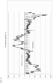
- FIG. 9 shows a waveform when the waveform of the current flowing through the servo motor is enlarged similarly to the reference waveform, and the enlargement ratio is 110% (pattern 1).
- FIG. 10 shows a waveform when the waveform of the current flowing through the servo motor is enlarged similarly to the reference waveform, and the enlargement ratio is 200% (pattern 2).
- FIG. 11 shows a waveform when the waveform of the current flowing through the servo motor has an oscillation tendency (pattern 3).
- FIG. 12 shows a waveform when a pulse component occurs in the waveform of the current flowing through the servo motor (pattern 4).
- the waveform of the current flowing through the servo motor at detection of the abnormality applies to any one of the four patterns, which pattern the waveform fits is detected and the fit pattern is stored. Then, the position where the abnormality has occurred is estimated from an item for which an alarm or warning is issued in the abnormality detection step and a waveform pattern of the current flowing through the servo motor at detection of the abnormality.
- a table related to a position where an abnormality has occurred is created in advance.
- This table indicates an estimated position where an abnormality has occurred in accordance with an item for which an alarm or warning has been issued and the waveform pattern of the current flowing through the servo motor at detection of the abnormality. Therefore, by referring to the table, it is possible to estimate a position where the abnormality has occurred from the item for which an alarm or warning is issued and the waveform pattern of the current flowing through the servo motor at detection of the abnormality.
- a type of value deviating from the prescribed range among the daily current values detected for a plurality of types of values, and the waveform of the current flowing through the servo motor at detection of occurrence of an abnormality, the position where the abnormality has occurred is estimated (estimation step).
- selection step it is selected which one of patterns 1 to 4 the waveform of the current flowing through the servo motor at detection of occurrence of an abnormality is applicable to (current value pattern selection step).
- FIG. 13 shows a table created in advance in relation to a position where an abnormality has occurred
- the waveform of the current flowing through the servo motor at that time is a waveform having an oscillation tendency (pattern 3), it is estimated that a lost motion (backlash) increases mainly in the reduction gear due to deterioration over time.
- the current flowing through the servo motor at that time is a waveform having a pulse (pattern 4).
- three cases of abnormality are considered.
- an abnormality has occurred in the harness used in the robot.
- an instantaneous short circuit or ground fault has occurred in the harness connected to a power line of a three-phase motor (line of three-phase motor).
- an abnormality has occurred in the harness used in the robot, and in particular, it is estimated that an instantaneous disconnection has occurred in the harness connected to the motor brake (motor brake line).
- the third case it is estimated that an abnormality has occurred in the servo motor. Specifically, it is considered that an internal magnet is damaged in the servo motor.
- the position where an abnormality has occurred is organized on a table in accordance with the type of the value deviating from the prescribed range and the waveform of the current flowing through the servo motor at detection of occurrence of the abnormality. Then, by referring to the table, the position where the abnormality has occurred is estimated.
- a position where the abnormality has occurred is empirically related to the item of the type of the value deviating from the prescribed range and the waveform of the current flowing through the servo motor at detection of occurrence of an abnormality.
- a table of a relationship between the median and the standard deviation of the mean square value and the median and the standard deviation of the peak value of the current flowing through the servo motor, and the waveform of the current flowing through the servo motor at detection of an abnormality is referred to. Then, the position where the abnormality has occurred is estimated. When occurrence of an abnormality is detected, the position where the abnormality has occurred is estimated on the basis of the table created in advance. Thus, the position where the abnormality is estimated to have occurred can be notified. The position where the abnormality has occurred is estimated, and the position where the abnormality has occurred is notified. The device can be therefore maintained by, for example, a replacement of a part in the notified position. This eliminates the need for locating the position where the abnormality has occurred, and saves trouble of locating the position.
- time for maintenance can be reduced, and the time during which the work cannot be performed because of maintenance can be reduced. Therefore, the work can be performed more efficiently, and operating costs can be reduced.
- the mean square value and the peak value of the value of the current flowing through the servo motor are calculated for each cycle, and the median of the mean square value and the peak value and the standard deviation of the mean square value and the peak value are calculated for each day. Then, by referring to the table, the waveform of the value of the current flowing through the servo motor is applied to a prescribed pattern to detect a position where an abnormality has occurred.
- the mean square value and the peak value for the position deviation of the servo motor may be calculated for each cycle, and the median of the mean square value and the peak value and the standard deviation of the mean square value and the peak value for the position deviation of the servo motor may be calculated for each day.
- a position where an abnormality has occurred may be detected by selecting, from the prescribed patterns, a pattern to which the waveform of the position deviation of the servo motor is applicable.
- the position deviation of the servo motor may be used as the observed value that is detected in the abnormality detection step or the position detection step and observed.
- the position deviation referred to herein is a deviation between a command value relating to a position and the actual position of the robot.
- the position deviation of the servo motor may be, for example, a difference between an angular position of the servo motor calculated backward from a position command value and an actual output result by an encoder.
- the position of the robot during the cycle may be the angular position of the servo motor calculated backward from the data (position data as a function of time).
- the position deviation of the servo motor is detected for each cycle (cycle position deviation detection step).
- the mean square value and the peak value for the position deviation of the servo motor in the prescribed operation are calculated for each cycle.
- the position deviation for each day is detected (daily position deviation detection step).
- the median of the mean square value is calculated for each day (position deviation mean square value median calculation step)
- the standard deviation of the mean square value is calculated for each day (position deviation mean square value standard deviation calculation step)
- the median of the peak value is calculated for each day (position deviation peak median calculation step)
- the standard deviation of the peak value is calculated for each day (position deviation peak standard deviation calculation step).
- the abnormality detection step when a representative value of the position deviation for each day deviates from a prescribed range, it is detected that an abnormality has occurred.
- a position detection step of detecting the position where the abnormality has occurred is performed.
- the position detection step from a type of value deviating from the prescribed range of the position deviation for each day detected for a plurality of types, and the waveform of the position deviation of the servo motor at detection of occurrence of the abnormality in the abnormality detection step, the position where the abnormality has occurred is estimated (estimation step).
- the position where an abnormality has occurred is organized on a table in accordance with the type of the value deviating from the prescribed range and the pattern of the waveform of the position deviation of the servo motor at detection of occurrence of the abnormality in the abnormality detection step.
- the position where the abnormality has occurred is estimated by referring to the table.
- FIGS. 14 and 15 show waveforms of the position deviation of the servo motor when an abnormality occurs.
- FIG. 14 is a graph showing a waveform of the position deviation of the servo motor when an oscillation tendency is observed with respect to a reference waveform.
- FIG. 15 is a graph showing a waveform of a position deviation of the servo motor when a pulse occurs with respect to the reference waveform.
- the waveform of the position deviation of the servo motor is a waveform with an oscillation tendency (pattern 5) or a waveform with a pulse (pattern 6) is determined from a result of the FFT analysis similarly to the determination from the waveform of the value of the current flowing through the servo motor, the waveform of the position deviation of the servo motor being subjected to the FFT analysis.
- pattern 5 the waveform of the position deviation of the servo motor being subjected to the FFT analysis.
- pattern the waveform of the position deviation of the servo motor is applicable is detected after the FFT analysis is subjected to the waveform of the position deviation of the servo motor, similarly to S601 to S603 ( FIG. 8 ) where the waveform of the current of the servo motor is detected.
- the waveform of the position deviation of the servo motor at detection of the abnormality is classified into pattern 6.
- FIG. 16 shows a table relating to a position where an abnormality has occurred in accordance with a type of value deviating from the prescribed range for the position deviation of the servo motor for each day and a waveform pattern of the position deviation of the servo motor when occurrence of the abnormality is detected in the abnormality detection step.
- a table of a relationship between the median and the standard deviation of the mean square value and the median and the standard deviation of the peak value for the position deviation of the servo motor, and the waveform of the position deviation of the servo motor at detection of an abnormality is referred to. Then, the position where the abnormality has occurred can be estimated. The position where the abnormality has occurred can be also estimated when the method is used of detecting the median and the standard deviation of the mean square value, and the median and the standard deviation of the peak value for the position deviation of the servo motor, and detecting a position where an abnormality has occurred on the basis of the waveform of the position deviation.
- an abnormality such as a break in the harness is likely to significantly affect the position deviation of the servo motor. Therefore, in order to confirm whether an abnormality has occurred in the harness in a more suitable manner, the median and the standard deviation of the mean square value and the median and the standard deviation of the peak value for the position deviation of the servo motor are calculated. Then, whether the abnormality has occurred is detected from these values. In addition, a position where the abnormality has occurred is detected using the waveform of the position deviation when the abnormality occurs. This makes it possible to more reliably detect whether an abnormality has occurred in the harness.
- the abnormality detection step and the position detection step may be performed by using the value of the current flowing through the servo motor and the position deviation of the servo motor in combination.
- the occurrence of an abnormality is detected from the combined detection result and the position where the abnormality has occurred is detected in the position detection step.
- the current (iu, iv, iw) flowing through each phase of the three-phase motor is converted into two axes of an id axis current (id) of a current that does not contribute to torque and an iq axis current (iq) as a torque component current that contributes to torque.
- id iq 2 3 cos ⁇ cos ⁇ ⁇ 2 ⁇ 3 cos ⁇ ⁇ 4 ⁇ 3 sin ⁇ sin ⁇ ⁇ 2 ⁇ 3 sin ⁇ ⁇ 4 ⁇ 3 iu iv iw
- Equation 2 The currents iu, iv, and iw are balanced three-phase alternating currents, and thus the current of each phase can be expressed as in Equation 2.
- iw Imcos ⁇ ⁇ 4 ⁇ 3
- Equation 3 ⁇ ⁇ ⁇ 2
- the current value is calculated with one value, a time-series waveform of the current command value can be represented in a graph. Accordingly, when the torque by the servo motor is constant, the torque component current value iq is constant, and can be easily calculated as one current value.
- iq/(2) 1/2 can be used as the current value.
- the mean square value and the peak value of the current value can be calculated for each cycle. It is thus possible to calculate a representative value of the value of the current flowing through the servo motor for each cycle. Further, a representative value of a current value for each day can be calculated from the representative value of the current value calculated for each cycle.
- the waveform of the value of the current flowing through the servo motor can be represented in a graph. This makes it possible to select which of the plurality of preset patterns the waveform of the current value is applicable to when an abnormality occurs. As a result, the position where the abnormality has occurred can be easily estimated.
Landscapes
- Engineering & Computer Science (AREA)
- Robotics (AREA)
- Mechanical Engineering (AREA)
- Physics & Mathematics (AREA)
- General Physics & Mathematics (AREA)
- Automation & Control Theory (AREA)
- Manipulator (AREA)
- Testing And Monitoring For Control Systems (AREA)
- Control Of Electric Motors In General (AREA)
- Human Computer Interaction (AREA)
Claims (7)
- Verfahren zum Schätzen einer Position, an der eine Anomalie bei einem Roboter (100) aufgetreten ist, der einen Arm unter Verwendung eines Servomotors antreibt, wobei das Verfahren umfasst:einen Anomalieerfassungsschritt (S101) des Erfassens, dass eine Anomalie aufgetreten ist;einen Positionserfassungsschritt (S103) des Erfassens, wenn das Auftreten der Anomalie in dem Anomalieerfassungsschritt (S101) erfasst wird, einer Position, an der die Anomalie aufgetreten ist;einen Zyklusbeobachtungswert-Erfassungsschritt des Beobachtens eines Übergangs eines Werts eines durch den Servomotor fließenden Stroms oder einer Positionsabweichung des Servomotors als einen Beobachtungswert und des Erfassens eines repräsentativen Werts des Beobachtungswerts für jeden Zyklus in einem vorgeschriebenen Vorgang eines Vorgangs für jeden Zyklus in einem Vorgang, der wiederholt von dem Roboter ausgeführt wird; undeinen Tagesbeobachtungswert-Erfassungsschritt des Erfassens eines repräsentativen Werts des Beobachtungswerts für jeden Tag aus dem repräsentativen Wert des Beobachtungswerts, der für jeden Zyklus erfasst wird, wobei, wenn der repräsentative Wert des Beobachtungswerts für jeden Tag von einem vorgeschriebenen Bereich abweicht, das Auftreten der Anomalie in dem Anomalieerfassungsschritt (S101) erfasst wird; undwobei der Positionserfassungsschritt (S103) einen Schätzschritt des Schätzens einer Position, an der die Anomalie aufgetreten ist, aus einem Werttyp, der von dem vorgeschriebenen Bereich des repräsentativen Werts des Beobachtungswerts für jeden Tag abweicht, der für eine Mehrzahl von Typen erfasst wird, und einer Wellenform umfasst, die durch eine Änderung des Beobachtungswerts im Laufe der Zeit erhalten wird, wenn das Auftreten der Anomalie in dem Anomalieerfassungsschritt (S101) erfasst wird;wobei in dem Zyklusbeobachtungswert-Erfassungsschritt ein quadratischer Mittelwert und ein Spitzenwert des Beobachtungswerts in dem vorgeschriebenen Vorgang für jeden Zyklus berechnet werden, undder Tagesbeobachtungswert-Erfassungsschritt umfasst:einen Quadratisches-Mittel-Median-Berechnungsschritt des Berechnens eines Medians quadratischen Mittelwerts für jeden Tag,einen Quadratisches-Mittel-Standardabweichung-Berechnungsschritt des Berechnens einer Standardabweichung des quadratischen Mittelwerts für jeden Tag,einen Spitzenmedian-Berechnungsschritt des Berechnens eines Medians des Spitzenwerts für jeden Tag, undeinen Spitzenstandardabweichung-Berechnungsschritt des Berechnens einer Standardabweichung des Spitzenwerts für jeden Tag.
- Verfahren zum Schätzen einer Position, an der eine Anomalie aufgetreten ist, nach Anspruch 1, wobeidie Position, an der die Anomalie aufgetreten ist, im Voraus in einer Tabelle gemäß dem Typ des vom vorgeschriebenen Bereich abweichenden Werts und der Wellenform organisiert wird, die durch Auftragen des Beobachtungswerts für jede Zeiteinheit erhalten wird, wenn das Auftreten der Anomalie in dem Anomalieerfassungsschritt (S101) erfasst wird, unddie Position, an der die Anomalie aufgetreten ist, mit Bezug auf die Tabelle in dem Schätzschritt geschätzt wird.
- Verfahren zum Schätzen einer Position, an der eine Anomalie aufgetreten ist, nach Anspruch 1, wobei das Auftreten der Anomalie in dem Anomalieerfassungsschritt (S101) erfasst wird, wenn einer der Werte von einem vorgeschriebenen Bereich abweicht, wobei die Werte der Median des in dem Quadratisches-Mittel-Median-Berechnungsschritt berechneten quadratischen Mittelwerts, die Standardabweichung des in dem Quadratisches-Mittel-Standardabweichung-Berechnungsschritt berechneten quadratischen Mittelwerts, der Median des in dem Spitzenmedian-Berechnungsschritt berechneten Spitzenwerts und die Standardabweichung des in dem Spitzenstandardabweichung-Berechnungsschritt berechneten Spitzenwerts sind.
- Verfahren zum Schätzen einer Position, an der eine Anomalie aufgetreten ist, nach einem der Ansprüche 1 bis 3, wobei der Schätzschritt einen Auswahlschritt des Auswählens umfasst, welches Muster aus einer Mehrzahl voreingestellter Muster der Wellenform des Beobachtungswerts bei Erfassung des Auftretens der Anomalie in dem Anomalieerfassungsschritt (S101) anwendbar ist.
- Verfahren zum Schätzen einer Position, an der eine Anomalie aufgetreten ist, nach Anspruch 4, wobeider Beobachtungswert ein Wert eines durch den Servomotor fließenden Stroms ist,in dem Auswahlschritt Muster 1 definiert wird, wenn die Wellenform des durch den Servomotor fließenden Stroms bei Erfassung des Auftretens der Anomalie in dem Anomalieerfassungsschritt (S101) ähnlich einer Referenzwellenform des durch den Servomotor fließenden Stroms ohne Auftreten der Anomalie vergrößert ist und ein Vergrößerungsverhältnis gleich oder kleiner als ein Schwellenwert ist, Muster 2 definiert wird, wenn das Vergrößerungsverhältnis größer als der Schwellenwert ist, Muster 3 definiert wird, wenn es eine Frequenz gibt, bei der eine Komponente der Wellenform des durch den Servomotor fließenden Stroms um einen bestimmten Betrag oder mehr größer ist als die Referenzwellenform und die Frequenz innerhalb eines vorgeschriebenen Frequenzbereichs liegt, und Muster 4 definiert wird, wenn die Frequenz nicht innerhalb des vorgeschriebenen Frequenzbereichs liegt, undder Auswahlschritt einen Stromwertmuster-Auswahlschritt des Auswählens umfasst, auf welches der Muster 1 bis 4 die Wellenform des durch den Servomotor fließenden Stroms bei Erfassung des Auftretens der Anomalie in dem Anomalieerfassungsschritt (S101) anwendbar ist.
- Verfahren zum Schätzen einer Position, an der eine Anomalie aufgetreten ist, nach Anspruch 4, wobeider Beobachtungswert eine Positionsabweichung des Servomotors ist,in dem Auswahlschritt Muster 5 definiert wird, wenn es eine Frequenz gibt, bei der eine Komponente der Wellenform der Positionsabweichung des Servomotors bei Erfassung des Auftretens der Anomalie in dem Anomalieerfassungsschritt (S101) um einen bestimmten Betrag oder mehr größer ist als eine Referenzwellenform der Positionsabweichung des Servomotors ohne Auftreten der Anomalie und die Frequenz innerhalb eines vorgeschriebenen Frequenzbereichs liegt, und Muster 6 definiert wird, wenn die Frequenz nicht innerhalb des vorgeschriebenen Frequenzbereichs liegt, undder Auswahlschritt einen Positionsabweichungsmuster-Auswahlschritt des Auswählens umfasst, auf welches der Muster 5 und 6 die Wellenform der Positionsabweichung des Servomotors bei Erfassung des Auftretens der Anomalie in dem Anomalieerfassungsschritt (S101) anwendbar ist.
- Computerprogramm, umfassend Anweisungen, die, wenn das Programm von einem Computer ausgeführt wird, den Computer veranlassen, das Verfahren nach Anspruch 1 auszuführen.
Applications Claiming Priority (2)
| Application Number | Priority Date | Filing Date | Title |
|---|---|---|---|
| JP2017193595A JP7021895B2 (ja) | 2017-10-03 | 2017-10-03 | 異常の生じた部位の推定方法及び異常の生じた部位の推定を行わせるプログラム |
| PCT/JP2018/036762 WO2019069877A1 (ja) | 2017-10-03 | 2018-10-02 | 異常の生じた部位の推定方法及び異常の生じた部位の推定を行わせるプログラム |
Publications (3)
| Publication Number | Publication Date |
|---|---|
| EP3693140A1 EP3693140A1 (de) | 2020-08-12 |
| EP3693140A4 EP3693140A4 (de) | 2021-07-28 |
| EP3693140B1 true EP3693140B1 (de) | 2024-07-03 |
Family
ID=65994326
Family Applications (1)
| Application Number | Title | Priority Date | Filing Date |
|---|---|---|---|
| EP18864190.6A Active EP3693140B1 (de) | 2017-10-03 | 2018-10-02 | Verfahren zur schätzung der position, an der eine anomalie erzeugt wurde, und programm zur ausführung der schätzung der position, an der eine anomalie erzeugt wurde |
Country Status (5)
| Country | Link |
|---|---|
| US (1) | US11241793B2 (de) |
| EP (1) | EP3693140B1 (de) |
| JP (1) | JP7021895B2 (de) |
| CN (1) | CN111148609B (de) |
| WO (1) | WO2019069877A1 (de) |
Families Citing this family (8)
| Publication number | Priority date | Publication date | Assignee | Title |
|---|---|---|---|---|
| KR102596214B1 (ko) * | 2019-07-04 | 2023-11-01 | 엘지전자 주식회사 | 로봇의 이상감지 시스템 및 그 제어방법 |
| JP6619908B1 (ja) * | 2019-09-13 | 2019-12-11 | 三菱重工業株式会社 | 診断装置、診断方法および診断プログラム |
| JP7396850B2 (ja) * | 2019-10-18 | 2023-12-12 | ファナック株式会社 | ロボット |
| JP2021084177A (ja) * | 2019-11-28 | 2021-06-03 | ファナック株式会社 | 無人搬送ロボットシステム |
| JP7477367B2 (ja) * | 2020-05-29 | 2024-05-01 | 株式会社日立製作所 | 異常機器判定システム |
| JP7452504B2 (ja) * | 2021-09-07 | 2024-03-19 | Jfeスチール株式会社 | プロセスの異常状態判定方法およびプロセスの異常状態判定装置 |
| CN116441817B (zh) * | 2022-01-07 | 2026-03-27 | 安川电机(中国)有限公司 | 伺服定位装置用工件定位异常确定方法及其装置 |
| CN117233602B (zh) * | 2023-11-07 | 2024-01-30 | 迈为技术(珠海)有限公司 | 刺晶机老化检测方法和刺晶机 |
Family Cites Families (16)
| Publication number | Priority date | Publication date | Assignee | Title |
|---|---|---|---|---|
| JPS59188517A (ja) * | 1983-04-11 | 1984-10-25 | Fanuc Ltd | サ−ボ制御系の絶対位置検出方式 |
| JPH06344293A (ja) * | 1993-06-03 | 1994-12-20 | Nissan Motor Co Ltd | 産業用ロボットの故障診断装置 |
| JP3267767B2 (ja) * | 1993-09-30 | 2002-03-25 | ジヤトコ・トランステクノロジー株式会社 | 被加工物用移動機構の監視装置 |
| JPH09311715A (ja) * | 1996-05-22 | 1997-12-02 | Fanuc Ltd | ロボットの異常発生履歴表示方法 |
| JPH10254539A (ja) * | 1997-03-10 | 1998-09-25 | Nissan Motor Co Ltd | 機械装置の駆動系の異常診断方法 |
| JP2001333594A (ja) * | 2000-05-22 | 2001-11-30 | Sony Corp | アクチュエータの負荷検出システム、及び、脚式移動ロボット |
| JP2004326417A (ja) * | 2003-04-24 | 2004-11-18 | Institute Of Physical & Chemical Research | 直動アクチュエータユニット |
| JP2005228732A (ja) * | 2004-01-15 | 2005-08-25 | Omron Corp | 故障検出装置 |
| JP4755593B2 (ja) * | 2004-06-29 | 2011-08-24 | Thk株式会社 | 異常検出方法およびモータ制御装置 |
| US9104650B2 (en) * | 2005-07-11 | 2015-08-11 | Brooks Automation, Inc. | Intelligent condition monitoring and fault diagnostic system for preventative maintenance |
| JP2008022590A (ja) * | 2006-07-10 | 2008-01-31 | Nachi Fujikoshi Corp | サーボモータ監視装置 |
| JP2008269349A (ja) * | 2007-04-20 | 2008-11-06 | Fanuc Ltd | 誤差過大検出機能を有する制御装置 |
| JP5910428B2 (ja) * | 2012-09-13 | 2016-04-27 | オムロン株式会社 | 監視装置、監視方法、プログラムおよび記録媒体 |
| WO2016103310A1 (ja) | 2014-12-26 | 2016-06-30 | 川崎重工業株式会社 | 搬送装置の制御装置 |
| US10730186B2 (en) * | 2015-05-21 | 2020-08-04 | Kastanienbaum GmbH | Method and device for open-loop/closed-loop control of an actuator-driven robot joint |
| JP6677198B2 (ja) * | 2017-03-16 | 2020-04-08 | トヨタ自動車株式会社 | ロボットの故障診断支援システム及び故障診断支援方法 |
-
2017
- 2017-10-03 JP JP2017193595A patent/JP7021895B2/ja active Active
-
2018
- 2018-10-02 US US16/753,407 patent/US11241793B2/en active Active
- 2018-10-02 EP EP18864190.6A patent/EP3693140B1/de active Active
- 2018-10-02 CN CN201880062326.3A patent/CN111148609B/zh active Active
- 2018-10-02 WO PCT/JP2018/036762 patent/WO2019069877A1/ja not_active Ceased
Also Published As
| Publication number | Publication date |
|---|---|
| JP7021895B2 (ja) | 2022-02-17 |
| EP3693140A4 (de) | 2021-07-28 |
| CN111148609A (zh) | 2020-05-12 |
| US20200306971A1 (en) | 2020-10-01 |
| WO2019069877A1 (ja) | 2019-04-11 |
| EP3693140A1 (de) | 2020-08-12 |
| JP2019067240A (ja) | 2019-04-25 |
| CN111148609B (zh) | 2023-10-20 |
| US11241793B2 (en) | 2022-02-08 |
Similar Documents
| Publication | Publication Date | Title |
|---|---|---|
| EP3693140B1 (de) | Verfahren zur schätzung der position, an der eine anomalie erzeugt wurde, und programm zur ausführung der schätzung der position, an der eine anomalie erzeugt wurde | |
| KR102584920B1 (ko) | 펌프 모니터링 장치 및 방법 | |
| JP6144404B1 (ja) | 減速機の故障診断装置及び故障診断方法並びに前記故障診断装置を備える機械装置 | |
| EP3637209B1 (de) | Bewegungsunempfindliche features zur zustandsbasierten wartung von fabrikrobotern | |
| JP6765320B2 (ja) | 交流電動機の制御装置 | |
| EP3173891B1 (de) | Steuerungsvorrichtung, steuerungsprogramm und aufzeichnungsmedium | |
| JP6406261B2 (ja) | 情報処理装置、及び、分析方法 | |
| CN101162394A (zh) | 异常诊断方法及其装置 | |
| JP2012194035A (ja) | 減速機異常診断装置および減速機異常診断方法 | |
| EP3715820A1 (de) | Verschlechterungsdiagnosevorrichtung für eine maschinenvorrichtung, verschlechterungsdiagnoseverfahren für eine maschinenvorrichtung, die in der verschlechterungsdiagnosevorrichtung ausgeführt wird, und verschlechterungsdiagnoseverfahren für die maschinenvorrichtung | |
| JP2018524185A (ja) | アクチュエータ駆動ロボットジョイントの開ループ/閉ループ制御のための方法および装置 | |
| US20180299838A1 (en) | Power-consumption-amount estimation apparatus | |
| WO2021145222A1 (ja) | 電力変換装置、回転機システム、及び診断方法 | |
| JP4073902B2 (ja) | 電動弁装置の異常および劣化診断手法ならびに装置 | |
| JP2021189706A (ja) | 異常機器判定システム | |
| CN115113040A (zh) | 电动机的异常诊断装置、异常诊断方法以及异常诊断程序 | |
| Klima et al. | Prognosis and Health Management in electric drives applications implemented in existing systems with limited data rate | |
| EP3691112B1 (de) | Datenerfassungsverfahren, wechselrichter und elektrische drehmaschine | |
| JP2011506987A (ja) | 機械装置のエネルギ消費量の分析方法および機械装置 | |
| JP2006158031A (ja) | モータ制御装置およびその制御方法 | |
| JP4538730B2 (ja) | モータ制御装置 | |
| JP2023110262A (ja) | ロボット診断装置、ロボット診断方法およびロボット診断プログラム | |
| JP7245994B2 (ja) | 異常診断装置及びそれを備えたロボット制御装置 | |
| JP7157582B2 (ja) | 電力変換装置、およびそれを用いたシステム | |
| JP2002132310A (ja) | 自動定期検診機能を有する工作機械 |
Legal Events
| Date | Code | Title | Description |
|---|---|---|---|
| STAA | Information on the status of an ep patent application or granted ep patent |
Free format text: STATUS: THE INTERNATIONAL PUBLICATION HAS BEEN MADE |
|
| PUAI | Public reference made under article 153(3) epc to a published international application that has entered the european phase |
Free format text: ORIGINAL CODE: 0009012 |
|
| STAA | Information on the status of an ep patent application or granted ep patent |
Free format text: STATUS: REQUEST FOR EXAMINATION WAS MADE |
|
| 17P | Request for examination filed |
Effective date: 20200430 |
|
| AK | Designated contracting states |
Kind code of ref document: A1 Designated state(s): AL AT BE BG CH CY CZ DE DK EE ES FI FR GB GR HR HU IE IS IT LI LT LU LV MC MK MT NL NO PL PT RO RS SE SI SK SM TR |
|
| AX | Request for extension of the european patent |
Extension state: BA ME |
|
| DAV | Request for validation of the european patent (deleted) | ||
| DAX | Request for extension of the european patent (deleted) | ||
| A4 | Supplementary search report drawn up and despatched |
Effective date: 20210629 |
|
| RIC1 | Information provided on ipc code assigned before grant |
Ipc: B25J 19/06 20060101AFI20210623BHEP Ipc: G05B 23/02 20060101ALI20210623BHEP Ipc: B25J 9/12 20060101ALI20210623BHEP Ipc: B25J 9/16 20060101ALI20210623BHEP |
|
| STAA | Information on the status of an ep patent application or granted ep patent |
Free format text: STATUS: EXAMINATION IS IN PROGRESS |
|
| 17Q | First examination report despatched |
Effective date: 20230424 |
|
| GRAP | Despatch of communication of intention to grant a patent |
Free format text: ORIGINAL CODE: EPIDOSNIGR1 |
|
| STAA | Information on the status of an ep patent application or granted ep patent |
Free format text: STATUS: GRANT OF PATENT IS INTENDED |
|
| INTG | Intention to grant announced |
Effective date: 20240212 |
|
| GRAS | Grant fee paid |
Free format text: ORIGINAL CODE: EPIDOSNIGR3 |
|
| GRAA | (expected) grant |
Free format text: ORIGINAL CODE: 0009210 |
|
| STAA | Information on the status of an ep patent application or granted ep patent |
Free format text: STATUS: THE PATENT HAS BEEN GRANTED |
|
| AK | Designated contracting states |
Kind code of ref document: B1 Designated state(s): AL AT BE BG CH CY CZ DE DK EE ES FI FR GB GR HR HU IE IS IT LI LT LU LV MC MK MT NL NO PL PT RO RS SE SI SK SM TR |
|
| REG | Reference to a national code |
Ref country code: CH Ref legal event code: EP |
|
| REG | Reference to a national code |
Ref country code: DE Ref legal event code: R096 Ref document number: 602018071410 Country of ref document: DE |
|
| REG | Reference to a national code |
Ref country code: LT Ref legal event code: MG9D |
|
| REG | Reference to a national code |
Ref country code: NL Ref legal event code: MP Effective date: 20240703 |
|
| PG25 | Lapsed in a contracting state [announced via postgrant information from national office to epo] |
Ref country code: PT Free format text: LAPSE BECAUSE OF FAILURE TO SUBMIT A TRANSLATION OF THE DESCRIPTION OR TO PAY THE FEE WITHIN THE PRESCRIBED TIME-LIMIT Effective date: 20241104 |
|
| REG | Reference to a national code |
Ref country code: AT Ref legal event code: MK05 Ref document number: 1699381 Country of ref document: AT Kind code of ref document: T Effective date: 20240703 |
|
| PG25 | Lapsed in a contracting state [announced via postgrant information from national office to epo] |
Ref country code: NL Free format text: LAPSE BECAUSE OF FAILURE TO SUBMIT A TRANSLATION OF THE DESCRIPTION OR TO PAY THE FEE WITHIN THE PRESCRIBED TIME-LIMIT Effective date: 20240703 |
|
| PG25 | Lapsed in a contracting state [announced via postgrant information from national office to epo] |
Ref country code: PT Free format text: LAPSE BECAUSE OF FAILURE TO SUBMIT A TRANSLATION OF THE DESCRIPTION OR TO PAY THE FEE WITHIN THE PRESCRIBED TIME-LIMIT Effective date: 20241104 Ref country code: NL Free format text: LAPSE BECAUSE OF FAILURE TO SUBMIT A TRANSLATION OF THE DESCRIPTION OR TO PAY THE FEE WITHIN THE PRESCRIBED TIME-LIMIT Effective date: 20240703 |
|
| PG25 | Lapsed in a contracting state [announced via postgrant information from national office to epo] |
Ref country code: NO Free format text: LAPSE BECAUSE OF FAILURE TO SUBMIT A TRANSLATION OF THE DESCRIPTION OR TO PAY THE FEE WITHIN THE PRESCRIBED TIME-LIMIT Effective date: 20241003 |
|
| PG25 | Lapsed in a contracting state [announced via postgrant information from national office to epo] |
Ref country code: GR Free format text: LAPSE BECAUSE OF FAILURE TO SUBMIT A TRANSLATION OF THE DESCRIPTION OR TO PAY THE FEE WITHIN THE PRESCRIBED TIME-LIMIT Effective date: 20241004 Ref country code: FI Free format text: LAPSE BECAUSE OF FAILURE TO SUBMIT A TRANSLATION OF THE DESCRIPTION OR TO PAY THE FEE WITHIN THE PRESCRIBED TIME-LIMIT Effective date: 20240703 Ref country code: PL Free format text: LAPSE BECAUSE OF FAILURE TO SUBMIT A TRANSLATION OF THE DESCRIPTION OR TO PAY THE FEE WITHIN THE PRESCRIBED TIME-LIMIT Effective date: 20240703 |
|
| PG25 | Lapsed in a contracting state [announced via postgrant information from national office to epo] |
Ref country code: BG Free format text: LAPSE BECAUSE OF FAILURE TO SUBMIT A TRANSLATION OF THE DESCRIPTION OR TO PAY THE FEE WITHIN THE PRESCRIBED TIME-LIMIT Effective date: 20240703 |
|
| PG25 | Lapsed in a contracting state [announced via postgrant information from national office to epo] |
Ref country code: LV Free format text: LAPSE BECAUSE OF FAILURE TO SUBMIT A TRANSLATION OF THE DESCRIPTION OR TO PAY THE FEE WITHIN THE PRESCRIBED TIME-LIMIT Effective date: 20240703 |
|
| PG25 | Lapsed in a contracting state [announced via postgrant information from national office to epo] |
Ref country code: IS Free format text: LAPSE BECAUSE OF FAILURE TO SUBMIT A TRANSLATION OF THE DESCRIPTION OR TO PAY THE FEE WITHIN THE PRESCRIBED TIME-LIMIT Effective date: 20241103 Ref country code: AT Free format text: LAPSE BECAUSE OF FAILURE TO SUBMIT A TRANSLATION OF THE DESCRIPTION OR TO PAY THE FEE WITHIN THE PRESCRIBED TIME-LIMIT Effective date: 20240703 |
|
| PG25 | Lapsed in a contracting state [announced via postgrant information from national office to epo] |
Ref country code: CZ Free format text: LAPSE BECAUSE OF FAILURE TO SUBMIT A TRANSLATION OF THE DESCRIPTION OR TO PAY THE FEE WITHIN THE PRESCRIBED TIME-LIMIT Effective date: 20240703 Ref country code: HR Free format text: LAPSE BECAUSE OF FAILURE TO SUBMIT A TRANSLATION OF THE DESCRIPTION OR TO PAY THE FEE WITHIN THE PRESCRIBED TIME-LIMIT Effective date: 20240703 |
|
| PG25 | Lapsed in a contracting state [announced via postgrant information from national office to epo] |
Ref country code: ES Free format text: LAPSE BECAUSE OF FAILURE TO SUBMIT A TRANSLATION OF THE DESCRIPTION OR TO PAY THE FEE WITHIN THE PRESCRIBED TIME-LIMIT Effective date: 20240703 Ref country code: RS Free format text: LAPSE BECAUSE OF FAILURE TO SUBMIT A TRANSLATION OF THE DESCRIPTION OR TO PAY THE FEE WITHIN THE PRESCRIBED TIME-LIMIT Effective date: 20241003 |
|
| PG25 | Lapsed in a contracting state [announced via postgrant information from national office to epo] |
Ref country code: RS Free format text: LAPSE BECAUSE OF FAILURE TO SUBMIT A TRANSLATION OF THE DESCRIPTION OR TO PAY THE FEE WITHIN THE PRESCRIBED TIME-LIMIT Effective date: 20241003 Ref country code: PL Free format text: LAPSE BECAUSE OF FAILURE TO SUBMIT A TRANSLATION OF THE DESCRIPTION OR TO PAY THE FEE WITHIN THE PRESCRIBED TIME-LIMIT Effective date: 20240703 Ref country code: NO Free format text: LAPSE BECAUSE OF FAILURE TO SUBMIT A TRANSLATION OF THE DESCRIPTION OR TO PAY THE FEE WITHIN THE PRESCRIBED TIME-LIMIT Effective date: 20241003 Ref country code: LV Free format text: LAPSE BECAUSE OF FAILURE TO SUBMIT A TRANSLATION OF THE DESCRIPTION OR TO PAY THE FEE WITHIN THE PRESCRIBED TIME-LIMIT Effective date: 20240703 Ref country code: IS Free format text: LAPSE BECAUSE OF FAILURE TO SUBMIT A TRANSLATION OF THE DESCRIPTION OR TO PAY THE FEE WITHIN THE PRESCRIBED TIME-LIMIT Effective date: 20241103 Ref country code: HR Free format text: LAPSE BECAUSE OF FAILURE TO SUBMIT A TRANSLATION OF THE DESCRIPTION OR TO PAY THE FEE WITHIN THE PRESCRIBED TIME-LIMIT Effective date: 20240703 Ref country code: GR Free format text: LAPSE BECAUSE OF FAILURE TO SUBMIT A TRANSLATION OF THE DESCRIPTION OR TO PAY THE FEE WITHIN THE PRESCRIBED TIME-LIMIT Effective date: 20241004 Ref country code: FI Free format text: LAPSE BECAUSE OF FAILURE TO SUBMIT A TRANSLATION OF THE DESCRIPTION OR TO PAY THE FEE WITHIN THE PRESCRIBED TIME-LIMIT Effective date: 20240703 Ref country code: ES Free format text: LAPSE BECAUSE OF FAILURE TO SUBMIT A TRANSLATION OF THE DESCRIPTION OR TO PAY THE FEE WITHIN THE PRESCRIBED TIME-LIMIT Effective date: 20240703 Ref country code: CZ Free format text: LAPSE BECAUSE OF FAILURE TO SUBMIT A TRANSLATION OF THE DESCRIPTION OR TO PAY THE FEE WITHIN THE PRESCRIBED TIME-LIMIT Effective date: 20240703 Ref country code: BG Free format text: LAPSE BECAUSE OF FAILURE TO SUBMIT A TRANSLATION OF THE DESCRIPTION OR TO PAY THE FEE WITHIN THE PRESCRIBED TIME-LIMIT Effective date: 20240703 Ref country code: AT Free format text: LAPSE BECAUSE OF FAILURE TO SUBMIT A TRANSLATION OF THE DESCRIPTION OR TO PAY THE FEE WITHIN THE PRESCRIBED TIME-LIMIT Effective date: 20240703 |
|
| REG | Reference to a national code |
Ref country code: DE Ref legal event code: R097 Ref document number: 602018071410 Country of ref document: DE |
|
| PG25 | Lapsed in a contracting state [announced via postgrant information from national office to epo] |
Ref country code: SM Free format text: LAPSE BECAUSE OF FAILURE TO SUBMIT A TRANSLATION OF THE DESCRIPTION OR TO PAY THE FEE WITHIN THE PRESCRIBED TIME-LIMIT Effective date: 20240703 Ref country code: DK Free format text: LAPSE BECAUSE OF FAILURE TO SUBMIT A TRANSLATION OF THE DESCRIPTION OR TO PAY THE FEE WITHIN THE PRESCRIBED TIME-LIMIT Effective date: 20240703 Ref country code: RO Free format text: LAPSE BECAUSE OF FAILURE TO SUBMIT A TRANSLATION OF THE DESCRIPTION OR TO PAY THE FEE WITHIN THE PRESCRIBED TIME-LIMIT Effective date: 20240703 |
|
| PG25 | Lapsed in a contracting state [announced via postgrant information from national office to epo] |
Ref country code: EE Free format text: LAPSE BECAUSE OF FAILURE TO SUBMIT A TRANSLATION OF THE DESCRIPTION OR TO PAY THE FEE WITHIN THE PRESCRIBED TIME-LIMIT Effective date: 20240703 |
|
| PG25 | Lapsed in a contracting state [announced via postgrant information from national office to epo] |
Ref country code: SK Free format text: LAPSE BECAUSE OF FAILURE TO SUBMIT A TRANSLATION OF THE DESCRIPTION OR TO PAY THE FEE WITHIN THE PRESCRIBED TIME-LIMIT Effective date: 20240703 Ref country code: IT Free format text: LAPSE BECAUSE OF FAILURE TO SUBMIT A TRANSLATION OF THE DESCRIPTION OR TO PAY THE FEE WITHIN THE PRESCRIBED TIME-LIMIT Effective date: 20240703 |
|
| PLBE | No opposition filed within time limit |
Free format text: ORIGINAL CODE: 0009261 |
|
| STAA | Information on the status of an ep patent application or granted ep patent |
Free format text: STATUS: NO OPPOSITION FILED WITHIN TIME LIMIT |
|
| REG | Reference to a national code |
Ref country code: CH Ref legal event code: PL |
|
| 26N | No opposition filed |
Effective date: 20250404 |
|
| PG25 | Lapsed in a contracting state [announced via postgrant information from national office to epo] |
Ref country code: MC Free format text: LAPSE BECAUSE OF FAILURE TO SUBMIT A TRANSLATION OF THE DESCRIPTION OR TO PAY THE FEE WITHIN THE PRESCRIBED TIME-LIMIT Effective date: 20240703 |
|
| PG25 | Lapsed in a contracting state [announced via postgrant information from national office to epo] |
Ref country code: BE Free format text: LAPSE BECAUSE OF NON-PAYMENT OF DUE FEES Effective date: 20241031 Ref country code: LU Free format text: LAPSE BECAUSE OF NON-PAYMENT OF DUE FEES Effective date: 20241002 |
|
| PG25 | Lapsed in a contracting state [announced via postgrant information from national office to epo] |
Ref country code: CH Free format text: LAPSE BECAUSE OF NON-PAYMENT OF DUE FEES Effective date: 20241031 |
|
| REG | Reference to a national code |
Ref country code: BE Ref legal event code: MM Effective date: 20241031 |
|
| PG25 | Lapsed in a contracting state [announced via postgrant information from national office to epo] |
Ref country code: SE Free format text: LAPSE BECAUSE OF FAILURE TO SUBMIT A TRANSLATION OF THE DESCRIPTION OR TO PAY THE FEE WITHIN THE PRESCRIBED TIME-LIMIT Effective date: 20240703 |
|
| PGFP | Annual fee paid to national office [announced via postgrant information from national office to epo] |
Ref country code: GB Payment date: 20250828 Year of fee payment: 8 |
|
| PGFP | Annual fee paid to national office [announced via postgrant information from national office to epo] |
Ref country code: FR Payment date: 20250908 Year of fee payment: 8 |
|
| PG25 | Lapsed in a contracting state [announced via postgrant information from national office to epo] |
Ref country code: IE Free format text: LAPSE BECAUSE OF NON-PAYMENT OF DUE FEES Effective date: 20241002 |
|
| PGFP | Annual fee paid to national office [announced via postgrant information from national office to epo] |
Ref country code: DE Payment date: 20250902 Year of fee payment: 8 |
|
| PG25 | Lapsed in a contracting state [announced via postgrant information from national office to epo] |
Ref country code: CY Free format text: LAPSE BECAUSE OF FAILURE TO SUBMIT A TRANSLATION OF THE DESCRIPTION OR TO PAY THE FEE WITHIN THE PRESCRIBED TIME-LIMIT; INVALID AB INITIO Effective date: 20181002 |
|
| PG25 | Lapsed in a contracting state [announced via postgrant information from national office to epo] |
Ref country code: HU Free format text: LAPSE BECAUSE OF FAILURE TO SUBMIT A TRANSLATION OF THE DESCRIPTION OR TO PAY THE FEE WITHIN THE PRESCRIBED TIME-LIMIT; INVALID AB INITIO Effective date: 20181002 |