EP3693308B1 - Fadenspeicherrohr für eine arbeitsstelle einer textilmaschine sowie arbeitsstelle einer textilmaschine - Google Patents
Fadenspeicherrohr für eine arbeitsstelle einer textilmaschine sowie arbeitsstelle einer textilmaschine Download PDFInfo
- Publication number
- EP3693308B1 EP3693308B1 EP20151304.1A EP20151304A EP3693308B1 EP 3693308 B1 EP3693308 B1 EP 3693308B1 EP 20151304 A EP20151304 A EP 20151304A EP 3693308 B1 EP3693308 B1 EP 3693308B1
- Authority
- EP
- European Patent Office
- Prior art keywords
- thread
- sensor
- area
- storage tube
- yarn
- Prior art date
- Legal status (The legal status is an assumption and is not a legal conclusion. Google has not performed a legal analysis and makes no representation as to the accuracy of the status listed.)
- Active
Links
Images



Classifications
-
- B—PERFORMING OPERATIONS; TRANSPORTING
- B65—CONVEYING; PACKING; STORING; HANDLING THIN OR FILAMENTARY MATERIAL
- B65H—HANDLING THIN OR FILAMENTARY MATERIAL, e.g. SHEETS, WEBS, CABLES
- B65H51/00—Forwarding filamentary material
- B65H51/20—Devices for temporarily storing filamentary material during forwarding, e.g. for buffer storage
- B65H51/22—Reels or cages, e.g. cylindrical, with storing and forwarding surfaces provided by rollers or bars
-
- B—PERFORMING OPERATIONS; TRANSPORTING
- B65—CONVEYING; PACKING; STORING; HANDLING THIN OR FILAMENTARY MATERIAL
- B65H—HANDLING THIN OR FILAMENTARY MATERIAL, e.g. SHEETS, WEBS, CABLES
- B65H51/00—Forwarding filamentary material
- B65H51/20—Devices for temporarily storing filamentary material during forwarding, e.g. for buffer storage
- B65H51/205—Devices for temporarily storing filamentary material during forwarding, e.g. for buffer storage by means of a fluid
-
- B—PERFORMING OPERATIONS; TRANSPORTING
- B65—CONVEYING; PACKING; STORING; HANDLING THIN OR FILAMENTARY MATERIAL
- B65H—HANDLING THIN OR FILAMENTARY MATERIAL, e.g. SHEETS, WEBS, CABLES
- B65H51/00—Forwarding filamentary material
- B65H51/02—Rotary devices, e.g. with helical forwarding surfaces
- B65H51/04—Rollers, pulleys, capstans, or intermeshing rotary elements
- B65H51/08—Rollers, pulleys, capstans, or intermeshing rotary elements arranged to operate in groups or in co-operation with other elements
-
- B—PERFORMING OPERATIONS; TRANSPORTING
- B65—CONVEYING; PACKING; STORING; HANDLING THIN OR FILAMENTARY MATERIAL
- B65H—HANDLING THIN OR FILAMENTARY MATERIAL, e.g. SHEETS, WEBS, CABLES
- B65H63/00—Warning or safety devices, e.g. automatic fault detectors, stop-motions ; Quality control of the package
-
- B—PERFORMING OPERATIONS; TRANSPORTING
- B65—CONVEYING; PACKING; STORING; HANDLING THIN OR FILAMENTARY MATERIAL
- B65H—HANDLING THIN OR FILAMENTARY MATERIAL, e.g. SHEETS, WEBS, CABLES
- B65H63/00—Warning or safety devices, e.g. automatic fault detectors, stop-motions ; Quality control of the package
- B65H63/06—Warning or safety devices, e.g. automatic fault detectors, stop-motions ; Quality control of the package responsive to presence of irregularities in running material, e.g. for severing the material at irregularities ; Control of the correct working of the yarn cleaner
- B65H63/062—Electronic slub detector
- B65H63/065—Electronic slub detector using photo-electric sensing means, i.e. the defect signal is a variation of light energy
-
- B—PERFORMING OPERATIONS; TRANSPORTING
- B65—CONVEYING; PACKING; STORING; HANDLING THIN OR FILAMENTARY MATERIAL
- B65H—HANDLING THIN OR FILAMENTARY MATERIAL, e.g. SHEETS, WEBS, CABLES
- B65H2701/00—Handled material; Storage means
- B65H2701/30—Handled filamentary material
- B65H2701/31—Textiles threads or artificial strands of filaments
Definitions
- Known textile machines have a large number of work stations of the type mentioned at the outset which are arranged adjacent to one another and at which a thread is wound onto a spool, for example a cross-wound spool.
- a thread is produced on a spinning machine from a fiber structure that has been presented and which, after leaving the spinning unit—viewed in the direction of the thread path—successively, d. H. Viewed in the transport direction of the thread, the take-off device arranged one behind the other and the thread store are passed and finally wound up on the thread winding device.
- the known spinning machines include, in particular, air-jet spinning and rotor spinning machines, which are basically known from the prior art.
- a so-called thread monitor in the area of the thread path, i.e. in the example of the spinning machine between the spinning unit and the thread winding device, which is a thread sensor connected to a controller for the work station, which detects an unintentional tearing of the thread as well as errors in the spun thread.
- the respective work process is interrupted via the control of the work station. If the thread is damaged, a cleaner cut must be carried out in which the damaged area of the thread is removed. If the thread breaks, a section of the end of the thread is removed. In both cases, the thread ends are then connected. On a spinning machine, for example, the thread end coming from the winding device is then fed to the spinning unit, in which a piecing process is carried out again, as a result of which the spinning process can be resumed.
- the thread monitor is usually arranged on the control of the work station arranged in the course of the thread, as in FIG DE 10 2007 040 184 A1 described.
- the control and the thread monitor form a unit.
- the thread monitor can also be arranged as a separate component in the area between the take-off device and a thread store arranged downstream of the take-off device, as shown in FIG EP 1 954 617 B1 or the closest prior art considered J DE 38 89 737 T2 known.
- the thread store serves to temporarily store a section of thread, with the term "intermediate storage” meaning the arrangement of a thread loop during transport from the spinning unit to the winding device within the thread storage device, so that fluctuations in the winding speed of the winding device and/or take-off device and fluctuations in the delivery speed of the spinning unit can be compensated for, which leads to a fluctuating filling level of the thread store.
- the invention is based on the object of providing a thread storage tube for a work station of a textile machine having a thread winding device and a work station of a textile machine which enables reliable monitoring of the yarn path and a compact design of the work station.
- the invention solves the problem by a workstation of a textile machine according to claim 1 and a thread storage tube for a thread winding device having workstation of a textile machine according to claim 8.
- Advantageous developments of the invention are specified in the dependent claims.
- a characteristic of the work station according to the invention is that the thread storage has a thread storage tube which is arranged with a thread entry opening in the area of the thread path and which is acted upon by an air flow directed from the thread entry opening in the direction of the interior of the thread storage tube, with a first thread sensor such as this in the area of the thread entry opening on the thread storage tube is integrated so that it monitors the thread path in the area in front of the thread entry opening, with a second thread sensor being integrated in the area of the thread entry opening of the thread storage tube on the thread storage tube and with the first thread sensor and the second thread sensor being arranged opposite one another on the thread entry opening.
- the yarn sensors and the yarn storage tube thus form a structural unit.
- the thread storage thus has a thread storage tube, which is arranged at the work site in such a way that a thread entry opening of the thread storage tube is adjacent to the thread run in regular winding operation of the thread winding device, this arrangement of the thread storage tube essentially consisting of the arrangement of the thread winding device to a thread source and possibly intermediate deflection points that determine the direction of the yarn.
- the thread storage tube is arranged in such a way that, in the state in which no section of the thread is arranged inside the thread storage tube, the thread runs in front of the thread entry opening.
- a thread storage tube is understood to mean a tubular body with a fundamentally arbitrary cross section, which has a thread entry opening at one end, through which the thread can enter the inside of the thread tube.
- the first thread sensor is arranged in the area of the thread entry opening in such a way that it reliably monitors the thread path in the area in front of the thread entry opening, ie detects a thread breakage and/or thread fault and controls the job reports.
- a corresponding arrangement of the thread sensor makes it possible to dispense with a separate arrangement of the thread sensor at the work site, resulting in a high degree of freedom in determining the path of the thread and an increase in functional reliability.
- the first thread sensor is designed in such a way that it monitors the course of the thread when no thread section is arranged inside the thread storage tube.
- the integration of the thread sensor on the thread storage tube results in a particularly high degree of flexibility in the design of the thread path, since it is possible to control the thread independently of the arrangement of the thread sensor obstruct.
- the thread sensor and the thread storage tube form a compact unit. A space-saving arrangement of the yarn sensor and the yarn storage tube is thus possible. The number of components is reduced and assembly is simplified.
- the first thread sensor is designed to monitor the course of the thread in the area in front of the thread entry opening.
- the first yarn sensor is designed to monitor the yarn run in the area in front of the yarn entry opening and the interior of the yarn storage tube.
- a corresponding configuration of the thread sensor makes it possible to monitor both the thread path in the event that a thread section is not arranged in the thread storage tube and in the case that a thread section is arranged inside the thread storage tube. This means that the first thread sensor detects the thread both when it runs correctly in front of the thread entry opening during regular operation and when the thread forms a thread loop inside the thread storage tube.
- a limitation of the suction air used for the thread store increases the possible piecing rate at a work station, for example, because then a higher amount of air is available at the spinning unit than is only available to a limited extent at the work station. This results in higher productivity at the workplace.
- the thread sensor As part of the monitoring carried out by the thread sensor, it recognizes this Presence of the thread and possibly also defects within the thread and forwards this information to the control, which interrupts the work process in the event of a thread break or the detection of an error.
- the arrangement of the first thread sensor in the area of the thread entry opening can in principle be freely selected, provided that it is positioned in an area that borders on the regular path of the thread.
- the thread storage tube is usually arranged in such a way that the peripheral edge of the thread storage tube on the face side borders the thread path twice, in areas lying opposite one another. Accordingly, the thread first passes through a first area of the thread storage tube which faces the thread source, for example a take-off device.
- the thread then passes through a second area of the thread storage tube, which is opposite the first area of the thread storage tube and faces the thread winding device.
- the first thread sensor is arranged in the second area of the thread storage tube that faces the thread winding device.
- the arrangement of the first yarn sensor in the second area enables a particularly good detection of the yarn path, with the position being particularly advantageously suitable for using the first yarn sensor according to an advantageous development of the invention to also detect the yarn path in the area of the interior of the yarn storage tube.
- the use of a single thread sensor is sufficient to record the thread path of the work station in the required manner.
- the work station has a second thread sensor.
- the second thread sensor is preferably arranged in such a way that it monitors the course of the thread in the area in front of the thread entry opening and/or inside the thread storage tube.
- the use of a second yarn sensor increases the reliability of detection of the yarn path in a special way.
- the use of a first and a second yarn sensor makes it possible, for example, to use one yarn sensor to detect the yarn run in the area in front of the yarn entry opening and the other yarn sensor to monitor the yarn run inside the yarn storage tube. This enables a particularly reliable alignment of the respective thread sensors according to their intended use.
- the second yarn sensor is also integrated on the yarn storage tube in the area of the yarn entry opening of the yarn storage tube. This results in a unit consisting of the thread storage tube, the first thread sensor and the second thread sensor.
- the arrangement of the second yarn sensor can be freely selected, provided that this is in the area of the yarn path. According to an advantageous development of the invention, however, it is provided that the second thread sensor is arranged in the first area of the thread storage tube arranged in the area of the thread path, which area faces the take-off device at a work location, for example. Accordingly, the second thread sensor is arranged in the area of the thread storage tube which—viewed in the direction of the thread run—is passed first by the thread.
- a corresponding arrangement in combination with the first thread sensor, which according to the invention is arranged opposite the thread entry opening on the thread storage tube, ensures a particularly reliable monitoring of the thread path.
- the second yarn sensor can also be arranged inside the yarn storage tube in the area of the yarn entry opening.
- the area in front of the yarn entry opening it is also possible to monitor the area in front of the yarn entry opening, provided this is outside the yarn path in regular operation of the work station, but within the yarn path of a yarn loop. This can be achieved by a corresponding design of the thread entry opening, which makes it possible to offset the second thread sensor against the first thread sensor transversely to the thread running direction.
- the configuration of the first and/or the second thread sensor can in principle be freely selected. For example, this can be designed to take place on a thread To detect reflection of a light source, which allows an adjacent arrangement of a photosensitive element and the light source. It is also possible to arrange the light source and the light-sensitive element opposite one another and to measure the light transmitted by the thread. According to a particularly advantageous embodiment of the invention, it is provided that the first thread sensor and/or the second thread sensor has a phototransistor and an infrared diode, which are particularly preferably arranged opposite one another.
- the use of a thread sensor designed in this way ensures, in a particularly reliable manner, both the detection of a thread breakage and the detection of faults within the thread. The use of appropriate thread sensors thus increases the quality of the thread and increases the reliability of the work process.
- the generation of an air flow directed towards the interior of the thread storage tube, starting from the thread inlet opening, can in principle take place in any manner, including, for example, suitable nozzles can be used which generate a correspondingly directed air flow within the thread storage tube.
- the yarn storage tube has an outlet opening which is opposite the yarn inlet opening and which is connected to a negative pressure source.
- This embodiment of the invention makes it possible in a particularly simple manner to generate an air flow directed towards the inside of the yarn storage tube within the yarn storage tube.
- a characteristic of the thread storage tube according to the invention for a workstation of a textile machine that has a thread winding device is that it has a first thread sensor integrated in the area of a thread entry opening on the thread storage tube, which is designed in such a way that it monitors the thread path in the area in front of the thread entry opening, with a second thread sensor is integrated on the thread storage tube in the area of the thread entry opening of the thread storage tube and wherein the first thread sensor and the second thread sensor are arranged opposite one another on the thread entry opening.
- a corresponding thread storage tube can be integrated in a known manner at a job and offers in addition to a simple and reliable monitoring of the thread path also the possibility of storing the thread in sections within the thread storage tube interior, with fluctuations in the winding speed can be compensated for with the stored thread section.
- the thread sensor according to the invention enables the thread path to be monitored within the thread storage tube, in the area in front of the thread storage tube and/or both in the area of the inside of the thread storage tube and in the area in front of the thread entry opening.
- a second thread sensor is arranged in the area of the thread entry opening.
- the second thread sensor is preferably designed in such a way that it monitors the thread path in the area in front of the thread entry opening and/or inside the thread storage tube.
- Both thread sensors can be designed to monitor both the thread path in the area in front of the thread entry opening and also inside the thread storage tube.
- the first thread sensor and the second thread sensor are arranged in mutually opposite areas of the thread storage tube, so that a particularly reliable monitoring of the thread path is ensured, with the thread storage tube then being arranged in such a way that it passes through the thread storage tube in the areas where the thread sensors are arranged .
- figure 1 shows a schematic representation of a work station 1 with a thread 6 extending during the spinning process, starting from a spinning unit 2, which is, for example, an air spinning or rotor spinning unit, to a thread winding device 5.
- a fiber composite 18 fed to the spinning unit 2 is Passing through a drafting system (not shown here) in the case of an air-jet spinning machine or an opening unit in the case of a rotor spinning machine within the spinning unit 2 with a twist.
- a take-off device 3 Downstream of the spinning unit 2 - in relation to the thread running direction 15 - is a take-off device 3 which, with the aid of two take-off rollers 14a, 14b forming a pair of take-off rollers, pulls the thread emerging from the spinning unit 2 out of the spinning unit 2 and transports it in the direction of the thread winding device 5. Downstream of the take-off device 3 is in turn a thread storage device 4 with a thread storage tube 7, on which a first thread sensor 10 and a second thread sensor 11 are integrated in the area of a thread entry opening 8, with the thread storage tube 7 being positioned in such a way that the thread sensors 10, 11 are in the area of the Grain are arranged.
- the yarn sensors 10, 11 form a sensor system by means of which the yarn path can be detected both in front of the yarn entry opening 8 and in the interior 9 of the yarn storage tube.
- the first yarn sensor 10 is used to detect the yarn path in the area in front of the yarn entry opening 8
- the second yarn sensor 11 is used to detect the yarn path inside the yarn storage tube 9 .
- the loop-shaped thread section arranged in the interior of the thread storage tube 9 is generated by suction air directed from the thread inlet opening 8 in the direction of the interior of the thread storage tube 9, which is provided by a negative pressure source 12, which is connected to an end of the thread storage tube 7 opposite the thread inlet opening 8.
- the extent to which the loop-shaped thread section extends inside the inside 9 of the thread storage tube is thus detected via the thread sensors 10 , 11 .
- the first thread sensor 10 is positioned at the thread entry opening 8 in such a way that it detects a thread 6 running in front of the thread entry opening 8 .
- the yarn path can be monitored in the area in front of the thread inlet opening 8 and the thread storage tube interior 9, since both in regular operation Workplace as well as a thread loop in the thread storage tube interior 9 at the position of the first thread sensor 10, a thread can be detected.
- the second yarn sensor 11 is arranged in the interior 9 of the yarn storage tube.
- the thread sensors 10, 11 are connected to a control of the work station, not shown here, which reduces the winding speed if the filling quantity is too low, whereas the winding speed is increased by the control if the thread storage tube interior 9 is too full, in order to maintain a constant Level within the thread storage tube interior 9 to reach.
- the spinning process is interrupted via the connected controller.
- a defined free thread end coming from the thread winding device 5 is then produced by means of a separating device 17 , which thread end is conveyed into the spinning unit 2 via return means 16 in a next step.
- the end of the thread is spun, i. H. it is connected to the thread 6 coming from the spinning unit 2 .
- the winding speed of the thread winding device 5 is determined by connecting the controller (not shown here) to a drive 13 of the thread winding device 5.
- a further embodiment of a thread storage device 4a with a thread storage tube 7a is shown in figure 4 with a thread arranged in front of the thread entry opening 8a and in figure 5 shown with a thread 6 arranged inside the thread storage tube 7a.
- the thread storage tube 7a does not generate any suction air in the area of the thread entry opening 8a, so that the thread 6 only passes through the thread storage 4a in the area of the first thread sensor 10a, which has a phototransistor 19 and an IR diode (not shown here) arranged opposite, which together have a Form light barrier that detects the thread 6.
- the yarn storage tube 7a is subjected to suction air, so that the yarn 6 is sucked into the interior of the yarn storage tube 7a.
- the thread 6 now runs with a thread loop inside the thread storage tube 7a and passes due to the resulting, compared to the in figure 4 shown thread path deviating thread path the second thread sensor 11a, which also has a phototransistor 19 and an oppositely arranged IR diode.
- the first thread sensor 10a is positioned at the thread entry opening 8a in such a way that it detects a thread 6 running in front of the thread entry opening 8a.
- the second thread sensor 11a is offset from the first thread sensor 10a transversely to the thread running direction. With this, a thread 6 running in the regular thread path, as in figure 4 shown, not detected by the second thread sensor 11a.
- the thread storage tube 7a is subjected to suction air, the thread 6 is pulled out of the regular thread path in the direction of the thread entry opening 8a and forms a thread loop. Then the second thread sensor 11a also detects the thread. If the thread loop inside the thread storage tube 7a is correct, the first thread sensor 10a continues to detect the thread 6.
- the information supplied by the thread sensors 10a, 11a is processed on a circuit board 21, which is connected to the control of the work station via lines that are not shown here.
- a transparent cover 20 arranged on an underside in the area of the second thread sensor 11a makes it possible to visually indicate the status of the thread storage 4a via suitable LEDs arranged on the thread storage 4a.
Landscapes
- Engineering & Computer Science (AREA)
- Textile Engineering (AREA)
- Quality & Reliability (AREA)
- Spinning Or Twisting Of Yarns (AREA)
- Filamentary Materials, Packages, And Safety Devices Therefor (AREA)
Description
- Die Erfindung betrifft ein Fadenspeicherrohr für eine eine Fadenaufspulvorrichtung aufweisende Arbeitsstelle einer Textilmaschine sowie eine Arbeitsstelle einer Textilmaschine, mit
- einem Fadenspeicher zur Zwischenspeicherung eines Fadenabschnitts und
- einer dem Fadenspeicher nachgelagerten Fadenaufspulvorrichtung.
- Bekannte Textilmaschinen weisen eine Vielzahl benachbart zueinander angeordnete Arbeitsstellen der eingangs genannten Art auf, an denen ein Faden auf eine Spule, bspw. eine Kreuzspule, aufgewickelt wird. So wird bspw. an einer Spinnmaschine aus einem vorgelegten Faserverband ein Faden hergestellt, der nach Verlassen der Spinneinheit - in Richtung des Fadenlaufs betrachtet - nacheinander, d. h. in Transportrichtung des Fadens betrachtet die hintereinanderliegend angeordnete Abzugseinrichtung und den Fadenspeicher passiert und abschließend auf der Fadenaufspulvorrichtung aufgewickelt wird. Dabei ist es nicht zwingend erforderlich, Fadenaufspulvorrichtung und Fadenspeicher unmittelbar aufeinanderfolgend anzuordnen, sondern es können auch weitere Komponenten zwischengeschaltet sein. Zu den bekannten Spinnmaschinen zählen dabei insbesondere Luftspinn- und Rotorspinnmaschinen, welche grundsätzlich aus dem Stand der Technik bekannt sind.
- Zur Überwachung des Fadenlaufs an den einzelnen Arbeitsstellen ist es bekannt, im Bereich des Fadenlaufs, d. h. am Beispiel der Spinnmaschine zwischen der Spinneinheit und der Fadenaufspulvorrichtung einen sogenannten Fadenwächter anzuordnen, bei dem es sich um einen mit einer Steuerung der Arbeitsstelle verbundenen Fadensensor handelt, welcher sowohl ein ungewolltes Reißen des Fadens als auch Fehler in dem gesponnenen Faden erkennt. In beiden Fällen wird über die Steuerung der Arbeitsstelle der jeweilige Arbeitsprozess unterbrochen. Bei einem schadhaften Faden ist ein Reinigerschnitt durchzuführen, bei dem der schadhafte Bereich des Fadens entfernt wird. Bei einem gerissenen Faden wird ein Abschnitt des Fadenendes entfernt. In beiden Fällen werden anschließend die Fadenenden verbunden. An einer Spinnmaschine wird bspw. anschließend das von der Aufspulvorrichtung kommende Fadenende der Spinneinheit zugeführt, in der wieder ein Anspinnvorgang durchgeführt wird, in dessen Folge der Spinnprozess wieder aufgenommen werden kann.
- Derzeit erfolgt die Anordnung des Fadenwächters üblicherweise an der im Fadenverlauf angeordneten Steuerung der Arbeitsstelle, wie in der
DE 10 2007 040 184 A1 beschrieben. Bei dieser Ausführung bilden die Steuerung und der Fadenwächter eine Baueinheit. Die Anordnung des Fadenwächters kann auch als separates Bauteil im Bereich zwischen der Abzugseinrichtung und einem der Abzugseinrichtung nachgeordneten Fadenspeicher erfolgen, wie aus derEP 1 954 617 B1 oder der als nächstliegenden Stand der Technik angesehenen JDE 38 89 737 T2 bekannt. Der Fadenspeicher dient dabei zum Zwischenspeichern eines Fadenabschnitts, wobei unter dem Begriff "Zwischenspeichern" die Anordnung einer Fadenschlaufe während des Transports von der Spinneinheit zur Aufspulvorrichtung innerhalb des Fadenspeichers verstanden wird, sodass Schwankungen in der Aufspulgeschwindigkeit der Aufspulvorrichtung und/oder Abzugseinrichtung sowie Schwankungen in der Liefergeschwindigkeit der Spinneinheit ausgeglichen werden können, wobei es hierbei zu einem schwankenden Füllstand des Fadenspeichers kommt. - Die derzeit bekannte Anordnung eines Fadensensors an der Steuerung der Arbeitsstelle weist den Nachteil auf, dass für eine zuverlässige Funktion des Fadenwächters die Steuerung zwingend in einem Bereich des Fadenlaufs vor der Aufspulvorrichtung anzuordnen ist. Aufgrund der Baugröße der Steuerung ergeben sich hierdurch jedoch Bauraumnachteile und weitrechende, konstruktive Restriktionen für die Anordnung und den Aufbau der jeweiligen Arbeitsstelle. Eine alternative Anordnung eines separaten Fadenwächters, bspw. im Bereich des Fadenspeichers liefert bei bekannten Arbeitsstellen eine nur unzureichende Erfassung des Fadenlaufs, insbesondere in einem Bereich vor dem Fadenspeicher, wenn dieser nicht durch einen Fadenabschnitt gefüllt ist. Zudem weist auch die Verwendung eines separaten Fadenwächters konstruktive Nachteile bei der Ausgestaltung der Arbeitsstelle auf.
- Hiervon ausgehend liegt der Erfindung die Aufgabe zugrunde, ein Fadenspeicherrohr für eine eine Fadenaufspulvorrichtung aufweisende Arbeitsstelle einer Textilmaschine sowie eine Arbeitsstelle einer Textilmaschine bereitzustellen, welche eine zuverlässige Überwachung des Fadenlaufs und eine kompakte Ausgestaltung der Arbeitsstelle ermöglicht.
- Die Erfindung löst die Aufgabe durch eine Arbeitsstelle einer Textilmaschine gemäß Anspruch 1 sowie ein Fadenspeicherrohr für eine Fadenaufspulvorrichtung aufweisende Arbeitsstelle einer Textilmaschine nach Anspruch 8. Vorteilhafte Weiterbildungen der Erfindung sind in den abhängigen Ansprüchen angegeben.
- Kennzeichnend für die erfindungsgemäße Arbeitsstelle ist, dass der Fadenspeicher ein mit einer Fadeneintrittsöffnung im Bereich des Fadenlaufs angeordnetes Fadenspeicherrohr aufweist, das mit einer von der Fadeneintrittsöffnung in Richtung auf das Fadenspeicherrohrinnere gerichteten Luftströmung beaufschlagt ist, wobei im Bereich der Fadeneintrittsöffnung an dem Fadenspeicherrohr ein erster Fadensensor derart integriert ist, dass dieser den Fadenlauf im Bereich vor der Fadeneintrittsöffnung überwacht, wobei ein zweiter Fadensensor im Bereich der Fadeneintrittsöffnung des Fadenspeicherrohrs an dem Fadenspeicherrohr integriert ist und wobei der erste Fadensensor und der zweite Fadensensor gegenüberliegend an der Fadeneintrittsöffnung angeordnet sind. Die Fadensensoren und das Fadenspeicherrohr bilden damit eine Baueinheit. Gemäß der Erfindung weist somit der Fadenspeicher ein Fadenspeicherrohr auf, das derart an der Arbeitsstelle angeordnet ist, dass eine Fadeneintrittsöffnung des Fadenspeicherrohres an den Fadenlauf im regulären Spulbetrieb der Fadenaufspulvorrichtung angrenzt, wobei diese Anordnung des Fadenspeicherrohres im Wesentlichen aus der Anordnung der Fadenaufspulvorrichtung zu einer Fadenquelle sowie ggf. zwischengeschalteter Umlenkpunkte resultiert, die den Fadenlauf vorgeben. Die Anordnung des Fadenspeicherrohres erfolgt derart, dass sich in dem Zustand, in dem kein Abschnitt des Fadens innerhalb des Fadenspeicherrohres angeordnet ist, der Faden vor der Fadeneintrittsöffnung verläuft. Unter einem Fadenspeicherrohr wird dabei im Rahmen der Erfindung ein Rohrkörper mit einem grundsätzlich beliebigen Querschnitt verstanden, welcher einenends eine Fadeneintrittsöffnung aufweist, über die der Faden in das Fadenrohrinnere gelangen kann.
- Eine Beaufschlagung des Fadenspeicherrohres mit einer Luftströmung derart, dass an der Fadeneintrittsöffnung einen Unterdruck besteht, durch den der vor der Fadeneintrittsöffnung verlaufende Faden in das Fadenspeicherrohrinnere gesaugt wird, gewährleistet die Anordnung eines schlaufenförmigen Fadenabschnitts innerhalb des Fadenspeicherrohrinneren. Der innerhalb des Fadenspeicherrohres angeordnete Fadenabschnitt ermöglicht es dann, Schwankungen in der Aufspulgeschwindigkeit auszugleichen, um so einem Fadenriss vorzubeugen.
- Erfindungsgemäß ist der erste Fadensensor dabei derart im Bereich der Fadeneintrittsöffnung angeordnet, dass dieser zuverlässig den Fadenlauf im Bereich vor der Fadeneintrittsöffnung überwacht, d. h. einen Fadenriss und/oder Fadenfehler erkennt und der Steuerung der Arbeitsstelle meldet. Eine entsprechende Anordnung des Fadensensors ermöglicht es, auf eine separate Anordnung des Fadensensors an der Arbeitsstelle zu verzichten, wodurch sich ein hoher Freiheitsgrad bei der Festlegung des Fadenlaufs sowie eine Steigerung der Funktionssicherheit ergibt. Der erste Fadensensor ist dabei derart ausgestaltet, dass er den Fadenlauf überwacht, wenn kein Fadenabschnitt innerhalb des Fadenspeicherrohres angeordnet ist. Gegenüber den aus dem Stand der Technik bekannten Anordnungen des Fadensensors an der Steuerung der Arbeitsstelle ergibt sich durch die Integration des Fadensensors an dem Fadenspeicherrohr eine besonders hohe Flexibilität bei der Gestaltung des Fadenlaufs, nachdem die Möglichkeit besteht, die Fadensteuerung unabhängig von der Anordnung des Fadensensors zu verbauen. Erfindungsgemäß bilden der Fadensensor und das Fadenspeicherrohr eine kompakte Baueinheit. Es ist damit eine platzsparende Anordnung des Fadensensors und des Fadenspeicherrohrs möglich. Die Anzahl der Bauteile wird reduziert und die Montage vereinfacht.
- Der erste Fadensensor ist gemäß der Erfindung zur Überwachung des Fadenlaufs im Bereich vor der Fadeneintrittsöffnung ausgebildet. Nach einer weiteren Ausgestaltung der Erfindung ist vorgesehen, dass der erste Fadensensor zur Überwachung des Fadenlaufs im Bereich vor der Fadeneintrittsöffnung und des Fadenspeicherrohrinneren ausgebildet ist. Eine entsprechende Ausgestaltung des Fadensensors ermöglicht es, sowohl den Fadenlauf im Falle einer nicht vorliegenden Anordnung eines Fadenabschnitts im Fadenspeicherrohr als auch im Falle der Anordnung eines Fadenabschnitts innerhalb des Fadenspeicherrohres zu überwachen. Das heißt, der erste Fadensensor detektiert den Faden sowohl, wenn dieser ordnungsgemäß während des regulären Betriebes vor der Fadeneintrittsöffnung läuft, als auch, wenn der Faden im Fadenspeicherrohrinneren eine Fadenschlaufe bildet.
- Eine Überwachung der Fadenschlaufe in dem Fadenspeicherrohrinneren ermöglicht es dabei, die zur Füllung des Fadenspeicherrohres notwendige Saugluft bedarfsgerecht zur Verfügung zu stellen, sodass die Effizienz der Arbeitsstelle gesteigert werden kann, nachdem durch ein rechtzeitiges Abschalten der Saugluft Energie eingespart werden kann. Eine Begrenzung der für den Fadenspeicher verwendeten Saugluft erhöht an einer Arbeitsstelle bspw. die mögliche Anspinnrate, weil dann eine höhere der nur begrenzt an der Arbeitsstelle zur Verfügung stehenden Luftmenge an der Spinneinheit zur Verfügung steht. Hierdurch resultiert eine höhere Produktivität der Arbeitsstelle.
- Im Rahmen der durch den Fadensensor durchgeführten Überwachung erkennt dieser das Vorhandensein des Fadens sowie ggf. auch Fehlstellen innerhalb des Fadens und leitet diese Informationen an die Steuerung weiter, welche im Falle eines Fadenrisses bzw. der Feststellung eines Fehlers den Arbeitsvorgang unterbricht. Die Anordnung des ersten Fadensensors im Bereich der Fadeneintrittsöffnung ist dabei grundsätzlich frei wählbar, sofern dieser in einem Bereich positioniert ist, der an den regulären Fadenlauf angrenzt. Üblicherweise erfolgt die Anordnung des Fadenspeicherrohres derart, dass der stirnseitig umlaufende Rand des Fadenspeicherrohres zweimal, an einander gegenüberliegenden Bereichen an den Fadenlauf angrenzt. Der Faden passiert demnach zuerst einen ersten Bereich des Fadenspeicherrohres, der der Fadenquelle, bspw. einer Abzugseinrichtung zugewandt ist. Hiernach passiert der Faden einen zweiten Bereich des Fadenspeicherrohres, der dem ersten Bereich des Fadenspeicherrohres gegenüberliegt und der Fadenaufspulvorrichtung zugewandt ist. Gemäß einer vorteilhaften Weiterbildung der Erfindung ist vorgesehen, dass der erste Fadensensor in dem zweiten Bereich des Fadenspeicherrohres angeordnet ist, der der Fadenaufspulvorrichtung zugewandt ist. Die Anordnung des ersten Fadensensors in dem zweiten Bereich ermöglicht eine besonders gute Erfassung des Fadenlaufs, wobei die Position in besonders vorteilhafterweise dazu geeignet ist, den ersten Fadensensor gemäß einer vorteilhaften Weiterbildung der Erfindung auch zur Erfassung des Fadenlaufs im Bereich des Fadenspeicherrohrinneren zu nutzen.
- Grundsätzlich ist die Verwendung eines einzelnen Fadensensors ausreichend, um den Fadenlauf der Arbeitsstelle in der geforderten Weise zu erfassen. Erfindungsgemäß ist jedoch vorgesehen, dass die Arbeitsstelle einen zweiten Fadensensor aufweist. Der zweite Fadensensor ist vorzugsweise derart angeordnet, dass dieser den Fadenlauf im Bereich vor der Fadeneintrittsöffnung und/oder im Fadenspeicherrohrinneren überwacht.
- Die Verwendung eines zweiten Fadensensors steigert die Zuverlässigkeit der Erfassung des Fadenlaufs in besonderer Weise. Die Verwendung von einem ersten und einem zweiten Fadensensor ermöglicht es bspw., einen Fadensensor zur Erfassung des Fadenlaufs im Bereich vor der Fadeneintrittsöffnung und den anderen Fadensensor zur Überwachung des Fadenlaufs innerhalb des Fadenspeicherrohres zu verwenden. Dies ermöglicht eine besonders zuverlässige Ausrichtung der jeweiligen Fadensensoren entsprechend deren Einsatzzweck. Darüber hinaus besteht jedoch grundsätzlich auch die Möglichkeit, die Erfassung der beiden Fadensensoren in beliebiger Weise zu kombinieren. Mit zwei Fadensensoren ist es damit möglich zwischen einem ordnungsgemäßen Fadenlauf vor der Fadeneintrittsöffnung und einer ordnungsgemäßen Fadenschlaufe in dem Fadenspeicherrohrinneren zu unterscheiden.
- Der zweite Fadensensor ist erfindungsgemäß im Bereich der Fadeneintrittsöffnung des Fadenspeicherrohrs ebenfalls an dem Fadenspeicherrohr integriert. Damit ergibt sich eine Baueinheit aus dem Fadenspeicherrohr, dem ersten Fadensensor und dem zweiten Fadensensor.
- Die Anordnung des zweiten Fadensensors ist, sofern dieser im Bereich des Fadenlaufs erfolgt, frei wählbar. Nach einer vorteilhaften Weiterbildung der Erfindung ist jedoch vorgesehen, dass der zweite Fadensensor in dem ersten im Bereich des Fadenlaufs angeordneten Bereich des Fadenspeicherrohres angeordnet ist, der an einer Arbeitsstelle bspw. der Abzugseinrichtung zugewandt ist. Demgemäß ist der zweite Fadensensor im Bereich des Fadenspeicherrohres angeordnet, der - in Richtung des Fadenlaufs betrachtet - zuerst von dem Faden passiert wird. Eine entsprechende Anordnung in Kombination mit dem ersten Fadensensor, welcher erfindungsgemäß gegenüberliegend an der Fadeneintrittsöffnung am Fadenspeicherrohr angeordnet ist, gewährleistet in besonderem Maße eine zuverlässige Überwachung des Fadenlaufs.
- Um insbesondere den Fadenlauf innerhalb des Fadenspeicherrohres zu überwachen, kann der zweite Fadensensor auch innerhalb des Fadenspeicherrohrinneren im Bereich der Fadeneintrittsöffnung angeordnet sein. Um den Fadenlauf innerhalb des Fadenspeicherrohrinneren zu überwachen, ist es auch möglich den Bereich vor der Fadeneintrittsöffnung zu überwachen, sofern dieser außerhalb des Fadenlaufs im regulären Betrieb der Arbeitsstelle liegt, jedoch innerhalb des Fadenlaufs einer Fadenschlaufe. Dies kann durch eine entsprechende Ausgestaltung der Fadeneintrittsöffnung erreicht werden, die es ermöglicht den zweiten Fadensensor gegen den ersten Fadensensor quer zur Fadenlaufrichtung zu versetzen. Durch eine Integration des zweiten Fadensensors, der den Fadenlauf innerhalb des Fadenspeicherrohrinneren überwacht, im Bereich der Fadeneintrittsöffnung des Fadenspeicherrohrs wird erreicht, dass der Zeitpunkt, zu dem eine Fadenschlaufe aufgelöst ist, relativ genau bestimmt werden kann. Das ist der Zeitpunkt, an dem die Saugluft abgeschaltet werden kann.
- Die Ausgestaltung des ersten und/oder des zweiten Fadensensors ist grundsätzlich frei wählbar. So kann dieser bspw. dazu ausgelegt sein, um die an einem Faden erfolgende Reflexion einer Lichtquelle zu erfassen, was eine benachbarte Anordnung eines lichtempfindlichen Elementes und der Lichtquelle erlaubt. Es ist auch möglich die Lichtquelle und das lichtempfindliche Element gegenüberliegend anzuordnen und das vom Faden transmittierte Licht zu messen. Nach einer besonders vorteilhaften Ausgestaltung der Erfindung ist vorgesehen, dass der erste Fadensensor und/oder der zweite Fadensensor einen Fototransistor und eine Infrarotdiode aufweist, die besonders bevorzugt gegenüberliegend angeordnet sind. Die Verwendung eines derart ausgestalteten Fadensensors gewährleistet in besonders zuverlässiger Weise sowohl eine Erkennung eines Fadenrisses als auch die Feststellung von Fehlern innerhalb des Fadens. Die Verwendung entsprechender Fadensensoren steigert somit die Qualität des Fadens und erhöht die Zuverlässigkeit des Arbeitsvorgangs.
- Die Erzeugung eines in Richtung auf das Fadenspeicherrohrinnere gerichteten Luftströmung ausgehend von der Fadeneintrittsöffnung kann grundsätzlich in beliebiger Weise erfolgen, wozu bspw. auch geeignete Düsen verwendet werden können, welche innerhalb des Fadenspeicherrohres einen entsprechend gerichteten Luftstrom erzeugen. Nach einer besonders vorteilhaften Ausgestaltung der Erfindung ist jedoch vorgesehen, dass das Fadenspeicherrohr eine der Fadeneintrittsöffnung gegenüberliegende Austrittsöffnung aufweist, die mit einer Unterdruckquelle verbunden ist. Diese Ausgestaltung der Erfindung ermöglicht es in besonders einfacher Weise, innerhalb des Fadenspeicherrohres eine in Richtung auf das Fadenspeicherrohrinnere gerichteten Luftströmung zu erzeugen. Insbesondere besteht die Möglichkeit, das Fadenspeicherrohr in einfacher Weise an die an der Arbeitsstelle vorhandene Saugluft anzuschließen, sodass auf eine separate Luftströmungserzeugung verzichtet werden kann.
- Kennzeichnend für das erfindungsgemäße Fadenspeicherrohr für eine eine Fadenaufspulvorrichtung aufweisende Arbeitsstelle einer Textilmaschine ist, dass dieser einen im Bereich einer Fadeneintrittsöffnung an dem Fadenspeicherrohr integrierten ersten Fadensensor aufweist, der derart ausgebildet ist, dass er den Fadenlauf im Bereich vor der Fadeneintrittsöffnung überwacht, wobei ein zweiter Fadensensor im Bereich der Fadeneintrittsöffnung des Fadenspeicherrohrs an dem Fadenspeicherrohr integriert ist und wobei der erste Fadensensor und der zweite Fadensensor gegenüberliegend an der Fadeneintrittsöffnung angeordnet sind. Ein entsprechendes Fadenspeicherrohr lässt sich in bekannter Weise an einer Arbeitsstelle integrieren und bietet neben einer einfachen und zuverlässigen Überwachung des Fadenlaufs zudem die Möglichkeit, den Faden abschnittsweise innerhalb des Fadenspeicherrohrinneren zu speichern, wobei mit dem gespeicherten Fadenabschnitt Schwankungen in der Aufspulgeschwindigkeit ausgeglichen werden können. Der erfindungsgemäße Fadensensor ermöglicht dabei die Überwachung des Fadenlaufs innerhalb des Fadenspeicherrohres, im Bereich vor dem Fadenspeicherrohr und/oder sowohl im Bereich des Fadenspeicherrohrinneren als auch im Bereich vor der Fadeneintrittsöffnung.
- Erfindungsgemäß ist vorgesehen, dass ein zweiter Fadensensor im Bereich der Fadeneintrittsöffnung angeordnet ist. Vorzugsweise ist der zweite Fadensensor derart ausgebildet, dass er den Fadenlauf im Bereich vor der Fadeneintrittsöffnung und/oder im Fadenspeicherrohrinneren überwacht. Die Verwendung von zwei Fadensensoren ermöglicht es somit, diese in optimaler Weise zu kombinieren, um den Fadenlauf sowohl im Fadenspeicherrohrinneren als auch im Bereich vor der Fadeneintrittsöffnung zuverlässig zu überwachen. Dabei können sowohl beide Fadensensoren dazu ausgelegt sein, sowohl den Fadenlauf im Bereich vor der Fadeneintrittsöffnung als auch im Fadenspeicherrohrinneren zu überwachen. Darüber hinaus ist auch eine Aufteilung der Erfassung möglich, wonach der eine Fadensensor den Fadenlauf im Bereich vor der Fadeneintrittsöffnung und der andere Fadensensor den Bereich im Fadenrohrinneren überwacht.
- Erfindungsgemäß sind der erste Fadensensor und der zweite Fadensensor in einander gegenüberliegenden Bereichen des Fadenspeicherrohres angeordnet, sodass eine besonders zuverlässige Überwachung des Fadenlaufs gewährleistet ist, wobei das Fadenspeicherrohr dann derart angeordnet ist, dass dieses das Fadenspeicherrohr in den Bereichen passiert, an denen die Fadensensoren angeordnet sind.
- Ein Ausführungsbeispiel der Erfindung wird nachstehend mit Bezug auf die Zeichnungen erläutert. In den Zeichnungen zeigen:
- Fig. 1
- eine schematische Darstellung einer Arbeitsstelle mit einem Fadenspeicherrohr;
- Fig. 2
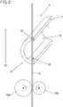
- in einer perspektivischen Ansicht eine schematische Darstellung der Arbeitsstelle von
Fig. 1 im Bereich eines ungefüllten Fadenspeicherrohres; - Fig. 3
- in einer perspektivischen Ansicht eine schematische Darstellung der Arbeitsstelle von
Fig. 1 im Bereich des mit einem Fadenabschnitt gefüllten Fadenspeicherrohres; - Fig. 4
- eine perspektivische Ansicht einer weiteren Ausführungsform eines Fadenspeichers mit einem ungefüllten Fadenspeicherrohr und
- Fig. 5
- eine perspektivische Ansicht des Fadenspeichers von
Fig. 4 mit einem mit einem Fadenabschnitt gefüllten Fadenspeicherrohr. -
Figur 1 zeigt eine schematische Darstellung einer Arbeitsstelle 1 mit einem sich während des Spinnvorgangs ausgehend von einer Spinneinheit 2, bei der es sich bspw. um eine Luftspinnoder Rotorspinneinheit handelt, bis zu einer Fadenaufspulvorrichtung 5 erstreckenden Faden 6. Ein der Spinneinheit 2 zugeführter Faserverbund 18 wird nach dem Durchlaufen eines hier nicht dargestellten Streckwerks im Falle einer Luftspinnmaschine oder einer Auflöseeinheit im Falle einer Rotorspinnmaschine innerhalb der Spinneinheit 2 mit einer Verdrehung versehen. - Der Spinneinheit 2 nachgelagert - bezogen auf die Fadenlaufrichtung 15 - ist eine Abzugseinrichtung 3, die mit Hilfe von zwei ein Abzugswalzenpaar bildenden Abzugswalzen 14a, 14b den aus der Spinneinheit 2 heraustretenden Faden aus der Spinneinheit 2 abzieht und in Richtung auf die Fadenaufspulvorrichtung 5 transportiert. Der Abzugseinrichtung 3 nachgelagert ist wiederum ein Fadenspeicher 4 mit einem Fadenspeicherrohr 7, an dem im Bereich einer Fadeneintrittsöffnung 8 ein erster Fadensensor 10 und ein zweiter Fadensensor 11 integriert sind, wobei das Fadenspeicherrohr 7 derart platziert ist, dass die Fadensensoren 10, 11 im Bereich des Fadenlaufs angeordnet sind.
- Die Fadensensoren 10, 11 bilden eine Sensorik, mittels der der Fadenlauf sowohl vor der Fadeneintrittsöffnung 8 als auch im Fadenspeicherrohrinneren 9 erfasst werden kann. In dem in den
Figuren 2 und3 dargestellten Ausführungsbeispiel dient dabei der erste Fadensensor 10 zur Erfassung des Fadenlaufs im Bereich vor der Fadeneintrittsöffnung 8 wohingegen der zweite Fadensensor 11 zur Erfassung des Fadenlaufs im Fadenspeicherrohrinneren 9 dient. Der im Fadenspeicherrohrinneren 9 angeordnete schlaufenförmige Fadenabschnitt wird dabei durch eine ausgehend von der Fadeneintrittsöffnung 8 in Richtung auf das Fadenspeicherrohrinnere 9 gerichteten Saugluft erzeugt, die durch eine Unterdruckquelle 12 bereitgestellt wird, welche mit einem der Fadeneintrittsöffnung 8 gegenüberliegenden Ende des Fadenspeicherrohres 7 verbunden ist. Über die Fadensensoren 10, 11 wird somit erfasst, in welchem Umfang sich der schlaufenförmige Fadenabschnitt innerhalb des Fadenspeicherrohrinneren 9 erstreckt. Der erste Fadensensor 10 ist so an der Fadeneintrittsöffnung 8 positioniert, dass dieser einen vor der Fadeneintrittsöffnung 8 laufenden Faden 6 detektiert. Damit kann der Fadenlauf im Bereich vor der Fadeneintrittsöffnung 8 und des Fadenspeicherrohrinneren 9 überwacht werden, da sowohl im regulären Betrieb der Arbeitsstelle als auch bei einer Fadenschlaufe im Fadenspeicherrohrinneren 9 an der Position des ersten Fadensensors 10 ein Faden detektiert werden kann. Der zweite Fadensensor 11 ist im Fadenspeicherrohrinneren 9 angeordnet. - Die Fadensensoren 10, 11 sind mit einer hier nicht dargestellten Steuerung der Arbeitsstelle verbunden, die im Falle einer zu geringen Füllmenge eine Reduzierung der Aufspulgeschwindigkeit vornimmt, wohingegen bei einer zu hohen Befüllung des Fadenspeicherrohrinneren 9 die Aufspulgeschwindigkeit durch die Steuerung erhöht wird, um so einen gleichbleibenden Füllstand innerhalb des Fadenspeicherrohrinneren 9 zu erreichen.
- Im Falle eines Reißens des Fadens 6 oder einem durch den Fadensensor 10, 11 erkannten Fadenfehlers erfolgt über die angeschlossene Steuerung eine Unterbrechung des Spinnvorgangs. Anschließend wird mittels einer Trennvorrichtung 17 ein definiertes freies, von der Fadenaufspulvorrichtung 5 kommendes Fadenende erzeugt, welches in einem nächsten Schritt über Rückführmittel 16 in die Spinneinheit 2 befördert wird. Hier wird das Fadenende angesponnen, d. h. es wird mit dem von der Spinneinheit 2 kommenden Faden 6 verbunden.
- Eine Festlegung der Aufspulgeschwindigkeit der Fadenaufspulvorrichtung 5 erfolgt über eine Verbindung der hier nicht dargestellten Steuerung mit einem Antrieb 13 der Fadenaufspulvorrichtung 5.
- Eine weitere Ausführungsform eines Fadenspeichers 4a mit einem Fadenspeicherrohr 7a ist in
Figur 4 mit einem vor der Fadeneintrittsöffnung 8a angeordneten Faden und inFigur 5 mit einem im Inneren des Fadenspeicherrohrs 7a angeordneten Faden 6 dargestellt. - In dem in
Figur 4 dargestellten Zustand erzeugt das Fadenspeicherrohr 7a keine Saugluft im Bereich der Fadeneintrittsöffnung 8a, sodass der Faden 6 den Fadenspeicher 4a allein im Bereich des ersten Fadensensors 10a passiert, welcher einen Fototransistor 19 sowie eine gegenüberliegend angeordnete, hier nicht dargestellte IR-Diode aufweist, welche gemeinsam eine Lichtschranke bilden, die den Faden 6 erfasst. - In dem in
Figur 5 dargestellten Zustand ist das Fadenspeicherrohr 7a mit Saugluft beaufschlagt, sodass der Faden 6 in das Innere des Fadenspeicherrohres 7a gesaugt ist. Der Faden 6 verläuft nunmehr mit einer Fadenschlaufe im Inneren des Fadenspeicherrohres 7a und passiert aufgrund des sich ergebenen, gegenüber dem inFigur 4 dargestellten Fadenverlauf abweichenden Fadenverlauf den zweiten Fadensensor 11a, welcher ebenfalls einen Fototransistor 19 sowie eine gegenüberliegend angeordnete IR-Diode aufweist. - Der erste Fadensensor 10a ist so an der Fadeneintrittsöffnung 8a positioniert, dass dieser einen vor der Fadeneintrittsöffnung 8a laufenden Faden 6 detektiert. Der zweite Fadensensor 11a ist gegenüber dem ersten Fadensensor 10a quer zur Fadenlaufrichtung versetzt. Damit wird ein im regulären Fadenlauf verlaufender Faden 6, wie in
Figur 4 dargestellt, von dem zweiten Fadensensor 11a nicht erfasst. Wenn das Fadenspeicherrohr 7a mit Saugluft beaufschlagt wird, wird der Faden 6 aus dem regulären Fadenlauf in Richtung der Fadeneintrittsöffnung 8a gezogen und bildet eine Fadenschlaufe. Dann erfasst auch der zweite Fadensensor 11a den Faden. Bei einer ordnungsgemäßen Fadenschlaufe im Inneren des Fadenspeicherrohrs 7a detektiert der erste Fadensensor 10a weiterhin den Faden 6. - Eine Verarbeitung der durch die Fadensensoren 10a, 11a gelieferten Informationen werden auf einer Platine 21 verarbeitet, welche über hier nicht dargestellte Leitungen mit der Steuerung der Arbeitsstelle verbunden ist. Eine an einer Unterseite im Bereich des zweiten Fadensensors 11a angeordnete transparente Abdeckung 20 ermöglicht es, über geeignete, an dem Fadenspeicher 4a angeordnete LEDs den Zustand des Fadenspeichers 4a optisch anzuzeigen.
-
- 1
- Arbeitsstelle
- 2
- Spinneinheit
- 3
- Abzugseinrichtung
- 4,4a
- Fadenspeicher
- 5
- Fadenaufspulvorrichtung
- 6
- Faden
- 7,7a
- Fadenspeicherrohr
- 8, 8a
- Fadeneintrittsöffnung
- 9
- Fadenspeicherrohrinnere
- 10, 10a
- erster Fadensensor
- 11, 11a
- zweiter Fadensensor
- 12
- Unterdruckquelle
- 13
- Antrieb
- 14a, 14b
- Antriebswalze
- 15
- Fadenlaufrichtung
- 16
- Rückführmittel
- 17
- Trennvorrichtung
- 18
- Faserverbund
- 19
- Fototransistor
- 20
- transparente Abdeckung
- 21
- Platine
Claims (9)
- Arbeitsstelle (1) einer Textilmaschine, mit- einem Fadenspeicher (4, 4a) zur Zwischenspeicherung eines Fadenabschnitts und- einer dem Fadenspeicher (4, 4a) nachgelagerten Fadenaufspulvorrichtung (5),wobei der Fadenspeicher (4, 4a) ein mit einer Fadeneintrittsöffnung (8, 8a) im Bereich des Fadenlaufs angeordnetes Fadenspeicherrohr (7, 7a) aufweist, das mit einer von der Fadeneintrittsöffnung (8, 8a) in Richtung auf das Fadenspeicherrohrinnere (9) gerichteten Luftströmung beaufschlagt ist, dadurch gekennzeichnet, dass im Bereich der Fadeneintrittsöffnung (8, 8a) an dem Fadenspeicherrohr (7, 7a) ein erster Fadensensor (10, 10a) derart integriert ist, dass dieser den Fadenlauf im Bereich vor der Fadeneintrittsöffnung (8, 8a) überwacht, dass ein zweiter Fadensensor (11, 11a) im Bereich der Fadeneintrittsöffnung (8, 8a) des Fadenspeicherrohrs (7, 7a) an dem Fadenspeicherrohr (7, 7a) integriert ist und dass der erste Fadensensor (10, 10a) und der zweite Fadensensor (11, 11a) gegenüberliegend an der Fadeneintrittsöffnung (8, 8a) angeordnet sind.
- Arbeitsstelle (1) nach Anspruch 1, dadurch gekennzeichnet, dass der erste Fadensensor (10, 10a) zur Überwachung des Fadenlaufs im Bereich vor der Fadeneintrittsöffnung (8, 8a) und des Fadenspeicherrohrinneren (9) ausgebildet ist.
- Arbeitsstelle (1) nach Anspruch 1 oder 2, dadurch gekennzeichnet, dass der erste Fadensensor (10, 10a) in einem zweiten im Bereich des Fadenlaufs angeordneten Bereich des Fadenspeicherrohres (7, 7a) angeordnet ist, der der Fadenaufspulvorrichtung (5) zugewandt ist.
- Arbeitsstelle (1) nach einem oder mehreren der vorhergehenden Ansprüche, dadurch gekennzeichnet, dass der zweite Fadensensor (11, 11a) derart an dem Fadenspeicherrohr (7, 7a) integriert ist, dass dieser den Fadenlauf im Bereich vor der Fadeneintrittsöffnung (8, 8a) und/oder im Fadenspeicherrohrinneren (9) überwacht.
- Arbeitsstelle (1) nach einem oder mehreren der vorhergehenden Ansprüche, dadurch gekennzeichnet, dass der zweite Fadensensor (11, 11a) in einem ersten im Bereich des Fadenlaufs angeordneten Bereich des Fadenspeicherrohres (7, 7a) angeordnet ist, der der Abzugseinrichtung (3) zugewandt ist.
- Arbeitsstelle (1) nach einem oder mehreren der vorhergehenden Ansprüche, dadurch gekennzeichnet, dass der erste Fadensensor (10, 10a) und/oder der zweite Fadensensor (11, 11a) einen Fototransistor (19) und eine Infrarotdiode aufweist.
- Arbeitsstelle (1) nach einem oder mehreren der vorhergehenden Ansprüche, dadurch gekennzeichnet, dass das Fadenspeicherrohr (7, 7a) eine der Fadeneintrittsöffnung (8, 8a) gegenüberliegende Austrittsöffnung aufweist, die mit einer Unterdruckquelle (12) verbunden ist.
- Fadenspeicherrohr (7, 7a) für eine eine Fadenaufspulvorrichtung (5) aufweisende Arbeitsstelle (1) einer Textilmaschine nach einem oder mehreren der Ansprüche 1 bis 7, gekennzeichnet durch einen im Bereich einer Fadeneintrittsöffnung (8, 8a) an dem Fadenspeicherrohr (7, 7a) integrierten ersten Fadensensor (10, 10a), der derart ausgebildet ist, dass er den Fadenlauf im Bereich vor der Fadeneintrittsöffnung (8) überwacht, wobei ein zweiter Fadensensor (11, 11a) im Bereich der Fadeneintrittsöffnung (8, 8a) des Fadenspeicherrohrs (7, 7a) an dem Fadenspeicherrohr (7, 7a) integriert ist und wobei der erste Fadensensor (10, 10a) und der zweite Fadensensor (11, 11a) gegenüberliegend an der Fadeneintrittsöffnung (8, 8a) angeordnet sind.
- Fadenspeicherrohr (7, 7a) nach Anspruch 8, dadurch gekennzeichnet, dass der zweite Fadensensor (11, 11a) derart ausgebildet ist, dass er den Fadenlauf im Bereich vor der Fadeneintrittsöffnung (8) und/oder im Fadenspeicherrohrinneren (9) überwacht.
Applications Claiming Priority (1)
| Application Number | Priority Date | Filing Date | Title |
|---|---|---|---|
| DE102019103193.1A DE102019103193A1 (de) | 2019-02-08 | 2019-02-08 | Fadenspeicherrohr für eine Arbeitsstelle einer Textilmaschine sowie Arbeitsstelle einer Textilmaschine |
Publications (2)
| Publication Number | Publication Date |
|---|---|
| EP3693308A1 EP3693308A1 (de) | 2020-08-12 |
| EP3693308B1 true EP3693308B1 (de) | 2022-06-15 |
Family
ID=69159586
Family Applications (1)
| Application Number | Title | Priority Date | Filing Date |
|---|---|---|---|
| EP20151304.1A Active EP3693308B1 (de) | 2019-02-08 | 2020-01-10 | Fadenspeicherrohr für eine arbeitsstelle einer textilmaschine sowie arbeitsstelle einer textilmaschine |
Country Status (3)
| Country | Link |
|---|---|
| EP (1) | EP3693308B1 (de) |
| CN (1) | CN111547566B (de) |
| DE (1) | DE102019103193A1 (de) |
Families Citing this family (1)
| Publication number | Priority date | Publication date | Assignee | Title |
|---|---|---|---|---|
| IT202000025831A1 (it) * | 2020-10-30 | 2022-04-30 | Savio Macch Tessili Spa | Stazione di filatura di una macchina di filatura a rotore con dispositivo di avvolgimento del filato migliorato, macchina di filatura a rotore e relativo metodo di filatura |
Family Cites Families (16)
| Publication number | Priority date | Publication date | Assignee | Title |
|---|---|---|---|---|
| EP0277717B1 (de) * | 1987-01-16 | 1994-06-01 | Toray Engineering Co., Ltd. | Fadenspulvorrichtung |
| US5079908A (en) * | 1988-08-27 | 1992-01-14 | Hans Stahlecker | Arrangement for carrying out a yarn piecing operation at a spinning point of a spinning machine |
| IT1255208B (it) * | 1991-07-25 | 1995-10-20 | Harald Dallmann | Procedimento e dispositivo per accumulare intermediamente fili per iniziare di nuovo la filatura |
| DE9420562U1 (de) * | 1994-12-22 | 1995-02-16 | Textilma Ag, Hergiswil | Bandwebmaschine |
| JP2005001879A (ja) * | 2003-06-11 | 2005-01-06 | Toshibumi Morihashi | 分繊機 |
| DE102004057825A1 (de) * | 2004-12-01 | 2006-06-08 | Saurer Gmbh & Co. Kg | Spulstelle einer Kreuzspule herstellenden Textilmaschine |
| ITMI20050605A1 (it) * | 2005-04-11 | 2006-10-12 | Savio Macchine Tessili Spa | Dispositivo di gestione del filo per carrelli di servizio per filatoi open-end |
| JP5002133B2 (ja) * | 2005-04-22 | 2012-08-15 | 津田駒工業株式会社 | 流体噴射式織機の貯留ドラムの緯糸解舒装置 |
| DE102005055717A1 (de) * | 2005-11-23 | 2007-05-24 | Saurer Gmbh & Co. Kg | Saugluftdüse für eine Textilmaschine |
| JP2007161449A (ja) * | 2005-12-15 | 2007-06-28 | Murata Mach Ltd | 糸巻取装置及び糸巻取方法 |
| DE102007040184A1 (de) | 2007-08-25 | 2009-02-26 | Oerlikon Textile Gmbh & Co. Kg | Elektronikeinheit für eine Kreuzspulen herstellende Textilmaschine |
| JP5007826B2 (ja) * | 2008-03-31 | 2012-08-22 | 村田機械株式会社 | 糸巻取装置及びこの糸巻取装置を備える自動ワインダ |
| DE102012102695A1 (de) * | 2012-03-29 | 2013-10-02 | Maschinenfabrik Rieter Ag | Vorspinnmaschine mit einer Anordnung zur Detektion und Entfernung von Garnfehlern |
| DE102013102770A1 (de) * | 2013-03-19 | 2014-09-25 | Maschinenfabrik Rieter Ag | Spinnstelle einer Spinnmaschine sowie Verfahren zum Betrieb derselben |
| CZ305558B6 (cs) * | 2014-12-03 | 2015-12-09 | Rieter Cz S.R.O. | Způsob řízení textilního stroje s alespoň jedním snímačem příze na pracovním místě |
| DE102015108740A1 (de) * | 2015-06-02 | 2016-12-08 | Rieter Ingolstadt Gmbh | Verfahren zum Betreiben einer Spinnmaschine mit arbeitsstelleneigenen Handlingsorganen zum Wiederanspinnen eines Fadens sowie Spinnmaschine mit arbeitsstelleneigenen Handlingsorganen |
-
2019
- 2019-02-08 DE DE102019103193.1A patent/DE102019103193A1/de not_active Withdrawn
-
2020
- 2020-01-10 EP EP20151304.1A patent/EP3693308B1/de active Active
- 2020-02-07 CN CN202010082449.2A patent/CN111547566B/zh active Active
Also Published As
| Publication number | Publication date |
|---|---|
| EP3693308A1 (de) | 2020-08-12 |
| CN111547566B (zh) | 2022-04-15 |
| CN111547566A (zh) | 2020-08-18 |
| DE102019103193A1 (de) | 2020-08-13 |
Similar Documents
| Publication | Publication Date | Title |
|---|---|---|
| EP2784193B1 (de) | Spinnstelle einer Spinnmaschine sowie Verfahren zum Betrieb derselben | |
| EP3052416B1 (de) | Garnreiniger sowie damit ausgerüstete spinnstelle einer spinnmaschine sowie verfahren zum betrieb einer spinnstelle | |
| EP2338818B1 (de) | Verfahren zum Betreiben einer Arbeitsstelle einer Spulmaschine und Arbeitsstelle einer Spulmaschine | |
| EP0419827B1 (de) | Verfahren zur Reinigung von Garnfehlern sowie Garnreiniger zur Durchführung des Verfahrens | |
| DE102007006679B4 (de) | Verfahren zum Betreiben einer Kreuzspulen herstellenden Textilmaschine | |
| DE19917968B4 (de) | Serviceaggregat für eine Kreuzspulen herstellende Textilmaschine | |
| DE19905860A1 (de) | Verfahren zum Betreiben einer Arbeitsstelle einer Kreuzspulen herstellenden Textilmaschine | |
| CH706572B1 (de) | Spinnmaschine. | |
| EP0679599A2 (de) | Faserband-Überwachungseinrichtung | |
| EP1928774B1 (de) | Verfahren zum betreiben einer arbeitsstelle einer kreuzspulen herstellenden textilmaschine | |
| EP3606855A1 (de) | Vorrichtung und verfahren zum ansaugen, zwischenspeichern und abführen eines fadens sowie textilmaschine | |
| EP3693308A1 (de) | Fadenspeicherrohr für eine arbeitsstelle einer textilmaschine sowie arbeitsstelle einer textilmaschine | |
| DE3805338A1 (de) | Verfahren und vorrichtung zum erzeugen von als vorlagespulen fuer ein zwirnen dienenden spulen | |
| DE102016101961A1 (de) | Sensoreinrichtung zum Detektieren von Materialfehlern und Verfahren hierzu | |
| CH697621B1 (de) | Verfahren und Textilmaschine zur Ausreinigung von Garnfehlern. | |
| DE3937824A1 (de) | Spulstelle einer spulmaschine, bei der das fadenverbinden und der kopswechsel automatisch durchfuehrbar sind | |
| EP3904253B1 (de) | Textilmaschine sowie servicewagen für textilmaschinen | |
| EP0419828B1 (de) | Verfahren zum Betrieb einer Spinnmaschine, insbesondere Ringspinnmaschine, sowie Bedienroboter zur Durchführung des Verfahrens | |
| DE1710062A1 (de) | Verfahren zur Steuerung des Wechsels der Abwickelspule bei automatischen Kreuzspulmaschinen | |
| DE10256293B4 (de) | Verfahren und Vorrichtung zum Betreiben einer Arbeitsstelle einer Kreuzspulen herstellenden Textilmaschine | |
| CH684790A5 (de) | Verfahren zur Reinigung von Garnfehlern an einer Spulstelle. | |
| EP0569772A2 (de) | Verfahren und Vorrichtung zum Herstellen einer vorgebbaren Anzahl voller Kreuzspulen auf einem Kreuzspulen herstellenden Automaten | |
| EP0024695B1 (de) | Fadenbruchüberwachung an aus mehreren Einzelfäden gefachten Gesamtfäden | |
| DE102019107712A1 (de) | Verfahren zum Herstellen einer Spleißverbindung an einer Arbeitsstelle einer Textilmaschine sowie Arbeitstelle einer Textilmaschine | |
| EP1982162A1 (de) | Vorrichtung und verfahren zum steuern einer tuftinganlage sowie entsprechende tuftinganlage |
Legal Events
| Date | Code | Title | Description |
|---|---|---|---|
| PUAI | Public reference made under article 153(3) epc to a published international application that has entered the european phase |
Free format text: ORIGINAL CODE: 0009012 |
|
| STAA | Information on the status of an ep patent application or granted ep patent |
Free format text: STATUS: THE APPLICATION HAS BEEN PUBLISHED |
|
| AK | Designated contracting states |
Kind code of ref document: A1 Designated state(s): AL AT BE BG CH CY CZ DE DK EE ES FI FR GB GR HR HU IE IS IT LI LT LU LV MC MK MT NL NO PL PT RO RS SE SI SK SM TR |
|
| AX | Request for extension of the european patent |
Extension state: BA ME |
|
| STAA | Information on the status of an ep patent application or granted ep patent |
Free format text: STATUS: REQUEST FOR EXAMINATION WAS MADE |
|
| 17P | Request for examination filed |
Effective date: 20210212 |
|
| RBV | Designated contracting states (corrected) |
Designated state(s): AL AT BE BG CH CY CZ DE DK EE ES FI FR GB GR HR HU IE IS IT LI LT LU LV MC MK MT NL NO PL PT RO RS SE SI SK SM TR |
|
| RIC1 | Information provided on ipc code assigned before grant |
Ipc: B65H 63/06 20060101ALI20220105BHEP Ipc: B65H 51/20 20060101AFI20220105BHEP |
|
| GRAP | Despatch of communication of intention to grant a patent |
Free format text: ORIGINAL CODE: EPIDOSNIGR1 |
|
| STAA | Information on the status of an ep patent application or granted ep patent |
Free format text: STATUS: GRANT OF PATENT IS INTENDED |
|
| INTG | Intention to grant announced |
Effective date: 20220215 |
|
| GRAS | Grant fee paid |
Free format text: ORIGINAL CODE: EPIDOSNIGR3 |
|
| GRAA | (expected) grant |
Free format text: ORIGINAL CODE: 0009210 |
|
| STAA | Information on the status of an ep patent application or granted ep patent |
Free format text: STATUS: THE PATENT HAS BEEN GRANTED |
|
| AK | Designated contracting states |
Kind code of ref document: B1 Designated state(s): AL AT BE BG CH CY CZ DE DK EE ES FI FR GB GR HR HU IE IS IT LI LT LU LV MC MK MT NL NO PL PT RO RS SE SI SK SM TR |
|
| REG | Reference to a national code |
Ref country code: CH Ref legal event code: EP Ref country code: GB Ref legal event code: FG4D Free format text: NOT ENGLISH |
|
| REG | Reference to a national code |
Ref country code: IE Ref legal event code: FG4D Free format text: LANGUAGE OF EP DOCUMENT: GERMAN |
|
| REG | Reference to a national code |
Ref country code: DE Ref legal event code: R096 Ref document number: 502020001221 Country of ref document: DE |
|
| REG | Reference to a national code |
Ref country code: AT Ref legal event code: REF Ref document number: 1498285 Country of ref document: AT Kind code of ref document: T Effective date: 20220715 |
|
| REG | Reference to a national code |
Ref country code: LT Ref legal event code: MG9D |
|
| REG | Reference to a national code |
Ref country code: NL Ref legal event code: MP Effective date: 20220615 |
|
| PG25 | Lapsed in a contracting state [announced via postgrant information from national office to epo] |
Ref country code: SE Free format text: LAPSE BECAUSE OF FAILURE TO SUBMIT A TRANSLATION OF THE DESCRIPTION OR TO PAY THE FEE WITHIN THE PRESCRIBED TIME-LIMIT Effective date: 20220615 Ref country code: NO Free format text: LAPSE BECAUSE OF FAILURE TO SUBMIT A TRANSLATION OF THE DESCRIPTION OR TO PAY THE FEE WITHIN THE PRESCRIBED TIME-LIMIT Effective date: 20220915 Ref country code: LT Free format text: LAPSE BECAUSE OF FAILURE TO SUBMIT A TRANSLATION OF THE DESCRIPTION OR TO PAY THE FEE WITHIN THE PRESCRIBED TIME-LIMIT Effective date: 20220615 Ref country code: HR Free format text: LAPSE BECAUSE OF FAILURE TO SUBMIT A TRANSLATION OF THE DESCRIPTION OR TO PAY THE FEE WITHIN THE PRESCRIBED TIME-LIMIT Effective date: 20220615 Ref country code: GR Free format text: LAPSE BECAUSE OF FAILURE TO SUBMIT A TRANSLATION OF THE DESCRIPTION OR TO PAY THE FEE WITHIN THE PRESCRIBED TIME-LIMIT Effective date: 20220916 Ref country code: FI Free format text: LAPSE BECAUSE OF FAILURE TO SUBMIT A TRANSLATION OF THE DESCRIPTION OR TO PAY THE FEE WITHIN THE PRESCRIBED TIME-LIMIT Effective date: 20220615 Ref country code: BG Free format text: LAPSE BECAUSE OF FAILURE TO SUBMIT A TRANSLATION OF THE DESCRIPTION OR TO PAY THE FEE WITHIN THE PRESCRIBED TIME-LIMIT Effective date: 20220915 |
|
| PG25 | Lapsed in a contracting state [announced via postgrant information from national office to epo] |
Ref country code: RS Free format text: LAPSE BECAUSE OF FAILURE TO SUBMIT A TRANSLATION OF THE DESCRIPTION OR TO PAY THE FEE WITHIN THE PRESCRIBED TIME-LIMIT Effective date: 20220615 Ref country code: LV Free format text: LAPSE BECAUSE OF FAILURE TO SUBMIT A TRANSLATION OF THE DESCRIPTION OR TO PAY THE FEE WITHIN THE PRESCRIBED TIME-LIMIT Effective date: 20220615 |
|
| PG25 | Lapsed in a contracting state [announced via postgrant information from national office to epo] |
Ref country code: NL Free format text: LAPSE BECAUSE OF FAILURE TO SUBMIT A TRANSLATION OF THE DESCRIPTION OR TO PAY THE FEE WITHIN THE PRESCRIBED TIME-LIMIT Effective date: 20220615 |
|
| PG25 | Lapsed in a contracting state [announced via postgrant information from national office to epo] |
Ref country code: SM Free format text: LAPSE BECAUSE OF FAILURE TO SUBMIT A TRANSLATION OF THE DESCRIPTION OR TO PAY THE FEE WITHIN THE PRESCRIBED TIME-LIMIT Effective date: 20220615 Ref country code: SK Free format text: LAPSE BECAUSE OF FAILURE TO SUBMIT A TRANSLATION OF THE DESCRIPTION OR TO PAY THE FEE WITHIN THE PRESCRIBED TIME-LIMIT Effective date: 20220615 Ref country code: RO Free format text: LAPSE BECAUSE OF FAILURE TO SUBMIT A TRANSLATION OF THE DESCRIPTION OR TO PAY THE FEE WITHIN THE PRESCRIBED TIME-LIMIT Effective date: 20220615 Ref country code: PT Free format text: LAPSE BECAUSE OF FAILURE TO SUBMIT A TRANSLATION OF THE DESCRIPTION OR TO PAY THE FEE WITHIN THE PRESCRIBED TIME-LIMIT Effective date: 20221017 Ref country code: ES Free format text: LAPSE BECAUSE OF FAILURE TO SUBMIT A TRANSLATION OF THE DESCRIPTION OR TO PAY THE FEE WITHIN THE PRESCRIBED TIME-LIMIT Effective date: 20220615 Ref country code: EE Free format text: LAPSE BECAUSE OF FAILURE TO SUBMIT A TRANSLATION OF THE DESCRIPTION OR TO PAY THE FEE WITHIN THE PRESCRIBED TIME-LIMIT Effective date: 20220615 |
|
| PG25 | Lapsed in a contracting state [announced via postgrant information from national office to epo] |
Ref country code: PL Free format text: LAPSE BECAUSE OF FAILURE TO SUBMIT A TRANSLATION OF THE DESCRIPTION OR TO PAY THE FEE WITHIN THE PRESCRIBED TIME-LIMIT Effective date: 20220615 Ref country code: IS Free format text: LAPSE BECAUSE OF FAILURE TO SUBMIT A TRANSLATION OF THE DESCRIPTION OR TO PAY THE FEE WITHIN THE PRESCRIBED TIME-LIMIT Effective date: 20221015 |
|
| REG | Reference to a national code |
Ref country code: DE Ref legal event code: R097 Ref document number: 502020001221 Country of ref document: DE |
|
| PG25 | Lapsed in a contracting state [announced via postgrant information from national office to epo] |
Ref country code: AL Free format text: LAPSE BECAUSE OF FAILURE TO SUBMIT A TRANSLATION OF THE DESCRIPTION OR TO PAY THE FEE WITHIN THE PRESCRIBED TIME-LIMIT Effective date: 20220615 |
|
| PLBE | No opposition filed within time limit |
Free format text: ORIGINAL CODE: 0009261 |
|
| STAA | Information on the status of an ep patent application or granted ep patent |
Free format text: STATUS: NO OPPOSITION FILED WITHIN TIME LIMIT |
|
| PG25 | Lapsed in a contracting state [announced via postgrant information from national office to epo] |
Ref country code: DK Free format text: LAPSE BECAUSE OF FAILURE TO SUBMIT A TRANSLATION OF THE DESCRIPTION OR TO PAY THE FEE WITHIN THE PRESCRIBED TIME-LIMIT Effective date: 20220615 |
|
| 26N | No opposition filed |
Effective date: 20230316 |
|
| PG25 | Lapsed in a contracting state [announced via postgrant information from national office to epo] |
Ref country code: SI Free format text: LAPSE BECAUSE OF FAILURE TO SUBMIT A TRANSLATION OF THE DESCRIPTION OR TO PAY THE FEE WITHIN THE PRESCRIBED TIME-LIMIT Effective date: 20220615 |
|
| PG25 | Lapsed in a contracting state [announced via postgrant information from national office to epo] |
Ref country code: LU Free format text: LAPSE BECAUSE OF NON-PAYMENT OF DUE FEES Effective date: 20230110 |
|
| REG | Reference to a national code |
Ref country code: BE Ref legal event code: MM Effective date: 20230131 |
|
| PG25 | Lapsed in a contracting state [announced via postgrant information from national office to epo] |
Ref country code: FR Free format text: LAPSE BECAUSE OF NON-PAYMENT OF DUE FEES Effective date: 20230131 Ref country code: BE Free format text: LAPSE BECAUSE OF NON-PAYMENT OF DUE FEES Effective date: 20230131 |
|
| PG25 | Lapsed in a contracting state [announced via postgrant information from national office to epo] |
Ref country code: IE Free format text: LAPSE BECAUSE OF NON-PAYMENT OF DUE FEES Effective date: 20230110 |
|
| PG25 | Lapsed in a contracting state [announced via postgrant information from national office to epo] |
Ref country code: MC Free format text: LAPSE BECAUSE OF FAILURE TO SUBMIT A TRANSLATION OF THE DESCRIPTION OR TO PAY THE FEE WITHIN THE PRESCRIBED TIME-LIMIT Effective date: 20220615 |
|
| PG25 | Lapsed in a contracting state [announced via postgrant information from national office to epo] |
Ref country code: MC Free format text: LAPSE BECAUSE OF FAILURE TO SUBMIT A TRANSLATION OF THE DESCRIPTION OR TO PAY THE FEE WITHIN THE PRESCRIBED TIME-LIMIT Effective date: 20220615 |
|
| GBPC | Gb: european patent ceased through non-payment of renewal fee |
Effective date: 20240110 |
|
| PG25 | Lapsed in a contracting state [announced via postgrant information from national office to epo] |
Ref country code: GB Free format text: LAPSE BECAUSE OF NON-PAYMENT OF DUE FEES Effective date: 20240110 |
|
| PG25 | Lapsed in a contracting state [announced via postgrant information from national office to epo] |
Ref country code: GB Free format text: LAPSE BECAUSE OF NON-PAYMENT OF DUE FEES Effective date: 20240110 |
|
| PG25 | Lapsed in a contracting state [announced via postgrant information from national office to epo] |
Ref country code: BG Free format text: LAPSE BECAUSE OF FAILURE TO SUBMIT A TRANSLATION OF THE DESCRIPTION OR TO PAY THE FEE WITHIN THE PRESCRIBED TIME-LIMIT Effective date: 20220615 |
|
| PG25 | Lapsed in a contracting state [announced via postgrant information from national office to epo] |
Ref country code: BG Free format text: LAPSE BECAUSE OF FAILURE TO SUBMIT A TRANSLATION OF THE DESCRIPTION OR TO PAY THE FEE WITHIN THE PRESCRIBED TIME-LIMIT Effective date: 20220615 |
|
| PGFP | Annual fee paid to national office [announced via postgrant information from national office to epo] |
Ref country code: AT Payment date: 20250417 Year of fee payment: 5 |
|
| PG25 | Lapsed in a contracting state [announced via postgrant information from national office to epo] |
Ref country code: CY Free format text: LAPSE BECAUSE OF FAILURE TO SUBMIT A TRANSLATION OF THE DESCRIPTION OR TO PAY THE FEE WITHIN THE PRESCRIBED TIME-LIMIT; INVALID AB INITIO Effective date: 20200110 |
|
| PG25 | Lapsed in a contracting state [announced via postgrant information from national office to epo] |
Ref country code: HU Free format text: LAPSE BECAUSE OF FAILURE TO SUBMIT A TRANSLATION OF THE DESCRIPTION OR TO PAY THE FEE WITHIN THE PRESCRIBED TIME-LIMIT; INVALID AB INITIO Effective date: 20200110 |
|
| PG25 | Lapsed in a contracting state [announced via postgrant information from national office to epo] |
Ref country code: TR Free format text: LAPSE BECAUSE OF FAILURE TO SUBMIT A TRANSLATION OF THE DESCRIPTION OR TO PAY THE FEE WITHIN THE PRESCRIBED TIME-LIMIT Effective date: 20220615 |
|
| PGFP | Annual fee paid to national office [announced via postgrant information from national office to epo] |
Ref country code: CZ Payment date: 20251230 Year of fee payment: 7 |
|
| REG | Reference to a national code |
Ref country code: CH Ref legal event code: U11 Free format text: ST27 STATUS EVENT CODE: U-0-0-U10-U11 (AS PROVIDED BY THE NATIONAL OFFICE) Effective date: 20260201 |
|
| REG | Reference to a national code |
Ref country code: AT Ref legal event code: MM01 Ref document number: 1498285 Country of ref document: AT Kind code of ref document: T Effective date: 20250110 |
|
| PGFP | Annual fee paid to national office [announced via postgrant information from national office to epo] |
Ref country code: DE Payment date: 20260120 Year of fee payment: 7 |
|
| PG25 | Lapsed in a contracting state [announced via postgrant information from national office to epo] |
Ref country code: AT Free format text: LAPSE BECAUSE OF NON-PAYMENT OF DUE FEES Effective date: 20250110 |
|
| PGFP | Annual fee paid to national office [announced via postgrant information from national office to epo] |
Ref country code: IT Payment date: 20260130 Year of fee payment: 7 |
|
| PGFP | Annual fee paid to national office [announced via postgrant information from national office to epo] |
Ref country code: CH Payment date: 20260201 Year of fee payment: 7 |