EP3694227B1 - Dispositif auditif comprenant un évent réglable - Google Patents
Dispositif auditif comprenant un évent réglable Download PDFInfo
- Publication number
- EP3694227B1 EP3694227B1 EP20150302.6A EP20150302A EP3694227B1 EP 3694227 B1 EP3694227 B1 EP 3694227B1 EP 20150302 A EP20150302 A EP 20150302A EP 3694227 B1 EP3694227 B1 EP 3694227B1
- Authority
- EP
- European Patent Office
- Prior art keywords
- valve
- vent
- hearing device
- hearing
- unit
- Prior art date
- Legal status (The legal status is an assumption and is not a legal conclusion. Google has not performed a legal analysis and makes no representation as to the accuracy of the status listed.)
- Active
Links
Images






Classifications
-
- H—ELECTRICITY
- H04—ELECTRIC COMMUNICATION TECHNIQUE
- H04R—LOUDSPEAKERS, MICROPHONES, GRAMOPHONE PICK-UPS OR LIKE ACOUSTIC ELECTROMECHANICAL TRANSDUCERS; ELECTRIC HEARING AIDS; PUBLIC ADDRESS SYSTEMS
- H04R25/00—Electric hearing aids
- H04R25/50—Customised settings for obtaining desired overall acoustical characteristics
-
- H—ELECTRICITY
- H04—ELECTRIC COMMUNICATION TECHNIQUE
- H04R—LOUDSPEAKERS, MICROPHONES, GRAMOPHONE PICK-UPS OR LIKE ACOUSTIC ELECTROMECHANICAL TRANSDUCERS; ELECTRIC HEARING AIDS; PUBLIC ADDRESS SYSTEMS
- H04R25/00—Electric hearing aids
- H04R25/45—Prevention of acoustic reaction, i.e. acoustic oscillatory feedback
- H04R25/456—Prevention of acoustic reaction, i.e. acoustic oscillatory feedback mechanically
-
- H—ELECTRICITY
- H04—ELECTRIC COMMUNICATION TECHNIQUE
- H04R—LOUDSPEAKERS, MICROPHONES, GRAMOPHONE PICK-UPS OR LIKE ACOUSTIC ELECTROMECHANICAL TRANSDUCERS; ELECTRIC HEARING AIDS; PUBLIC ADDRESS SYSTEMS
- H04R1/00—Details of transducers, loudspeakers or microphones
- H04R1/10—Earpieces; Attachments therefor ; Earphones; Monophonic headphones
- H04R1/1041—Mechanical or electronic switches, or control elements
-
- H—ELECTRICITY
- H04—ELECTRIC COMMUNICATION TECHNIQUE
- H04R—LOUDSPEAKERS, MICROPHONES, GRAMOPHONE PICK-UPS OR LIKE ACOUSTIC ELECTROMECHANICAL TRANSDUCERS; ELECTRIC HEARING AIDS; PUBLIC ADDRESS SYSTEMS
- H04R25/00—Electric hearing aids
- H04R25/48—Electric hearing aids using constructional means for obtaining a desired frequency response
-
- H—ELECTRICITY
- H04—ELECTRIC COMMUNICATION TECHNIQUE
- H04R—LOUDSPEAKERS, MICROPHONES, GRAMOPHONE PICK-UPS OR LIKE ACOUSTIC ELECTROMECHANICAL TRANSDUCERS; ELECTRIC HEARING AIDS; PUBLIC ADDRESS SYSTEMS
- H04R25/00—Electric hearing aids
- H04R25/50—Customised settings for obtaining desired overall acoustical characteristics
- H04R25/505—Customised settings for obtaining desired overall acoustical characteristics using digital signal processing
-
- H—ELECTRICITY
- H04—ELECTRIC COMMUNICATION TECHNIQUE
- H04R—LOUDSPEAKERS, MICROPHONES, GRAMOPHONE PICK-UPS OR LIKE ACOUSTIC ELECTROMECHANICAL TRANSDUCERS; ELECTRIC HEARING AIDS; PUBLIC ADDRESS SYSTEMS
- H04R2225/00—Details of deaf aids covered by H04R25/00, not provided for in any of its subgroups
- H04R2225/023—Completely in the canal [CIC] hearing aids
-
- H—ELECTRICITY
- H04—ELECTRIC COMMUNICATION TECHNIQUE
- H04R—LOUDSPEAKERS, MICROPHONES, GRAMOPHONE PICK-UPS OR LIKE ACOUSTIC ELECTROMECHANICAL TRANSDUCERS; ELECTRIC HEARING AIDS; PUBLIC ADDRESS SYSTEMS
- H04R2225/00—Details of deaf aids covered by H04R25/00, not provided for in any of its subgroups
- H04R2225/025—In the ear hearing aids [ITE] hearing aids
-
- H—ELECTRICITY
- H04—ELECTRIC COMMUNICATION TECHNIQUE
- H04R—LOUDSPEAKERS, MICROPHONES, GRAMOPHONE PICK-UPS OR LIKE ACOUSTIC ELECTROMECHANICAL TRANSDUCERS; ELECTRIC HEARING AIDS; PUBLIC ADDRESS SYSTEMS
- H04R2225/00—Details of deaf aids covered by H04R25/00, not provided for in any of its subgroups
- H04R2225/41—Detection or adaptation of hearing aid parameters or programs to listening situation, e.g. pub, forest
-
- H—ELECTRICITY
- H04—ELECTRIC COMMUNICATION TECHNIQUE
- H04R—LOUDSPEAKERS, MICROPHONES, GRAMOPHONE PICK-UPS OR LIKE ACOUSTIC ELECTROMECHANICAL TRANSDUCERS; ELECTRIC HEARING AIDS; PUBLIC ADDRESS SYSTEMS
- H04R2225/00—Details of deaf aids covered by H04R25/00, not provided for in any of its subgroups
- H04R2225/61—Aspects relating to mechanical or electronic switches or control elements, e.g. functioning
-
- H—ELECTRICITY
- H04—ELECTRIC COMMUNICATION TECHNIQUE
- H04R—LOUDSPEAKERS, MICROPHONES, GRAMOPHONE PICK-UPS OR LIKE ACOUSTIC ELECTROMECHANICAL TRANSDUCERS; ELECTRIC HEARING AIDS; PUBLIC ADDRESS SYSTEMS
- H04R2460/00—Details of hearing devices, i.e. of ear- or headphones covered by H04R1/10 or H04R5/033 but not provided for in any of their subgroups, or of hearing aids covered by H04R25/00 but not provided for in any of its subgroups
- H04R2460/11—Aspects relating to vents, e.g. shape, orientation, acoustic properties in ear tips of hearing devices to prevent occlusion
-
- H—ELECTRICITY
- H04—ELECTRIC COMMUNICATION TECHNIQUE
- H04R—LOUDSPEAKERS, MICROPHONES, GRAMOPHONE PICK-UPS OR LIKE ACOUSTIC ELECTROMECHANICAL TRANSDUCERS; ELECTRIC HEARING AIDS; PUBLIC ADDRESS SYSTEMS
- H04R25/00—Electric hearing aids
- H04R25/65—Housing parts, e.g. shells, tips or moulds, or their manufacture
- H04R25/652—Ear tips; Ear moulds
-
- H—ELECTRICITY
- H04—ELECTRIC COMMUNICATION TECHNIQUE
- H04R—LOUDSPEAKERS, MICROPHONES, GRAMOPHONE PICK-UPS OR LIKE ACOUSTIC ELECTROMECHANICAL TRANSDUCERS; ELECTRIC HEARING AIDS; PUBLIC ADDRESS SYSTEMS
- H04R25/00—Electric hearing aids
- H04R25/70—Adaptation of deaf aid to hearing loss, e.g. initial electronic fitting
Definitions
- the present disclosure relates to a hearing device comprising an adjustable vent, e.g. comprising a valve. More particularly, the disclosure relates to the hearing device configured to adjust said vent in response to a change in acoustic environment or to user actions, and to how said adjustable vent is designed.
- the hearing device may be constituted by or comprise a hearing aid.
- Hearing devices which are designed to be placed within an ear canal, are typically designed with a vent to avoid discomfort for the user (occlusion).
- a vent to avoid discomfort for the user (occlusion).
- This vent size is in most available hearing devices constant during use (e.g. determined in advance of the use of the hearing device, e.g. customized to a user's needs), and if it is possible to change the vent size, it is usually done by changing some mechanical parts, such as domes in hearing aid devices.
- it is beneficial to be able to change the vent size e.g. in cases when the hearing device has no vent, or a vent with only a small opening, and a user starts talking. Due to the occlusion effect, it may be uncomfortable for the user, and the option of adjusting the vent size (increasing its opening) would be attractive.
- the general knowledge related to determining the vent size for a given hearing device style and a given need of a user for amplification is known in the field of hearing devices. It is known, for example, that better sound attenuation (or sounds from the outside) is achieved with a closed vent (it is used in headsets with higher attenuation which allows to, for example, play music quieter and make less impact on hearing). It is also beneficial to keep the vent closed in the case of a need for high amplification of lower frequencies. On the other hand, while a user of the hearing device is talking, an open vent is a better solution. In the area of a hearing aids, it is usually a compromise between different, mutually excluding conditions.
- a hearing aid comprising: a housing having a contact portion configured to form a substantially sealed connection with a user's ear, the housing having a sound opening; an electroacoustic transducer disposed in the housing, the transducer configured to generate an acoustic signal in response to an electrical excitation signal applied thereto, wherein an acoustic signal generated by the transducer radiates into the user's ear via the sound opening when the portion of the housing is coupled to the user's ear; an acoustic valve disposed in an acoustic passageway of the housing, the acoustic valve operable to alter passage of sound through the acoustic passageway; a sensor configured to generate an output signal indicative of a state of the acoustic valve; an electrical circuit configured to actuate the acoustic valve based on the output signal of the sensor.
- the hearing aid comprises an earpiece for insertion into the ear canal of the user of the hearing aid.
- a through-going vent is provided in the earpiece and a receiver is provided in the earpiece.
- the hearing aid comprises activation means for automatically changing the acoustical impedance of the vent.
- D3 discloses a hearing aid with: a) an input unit comprising first and second input transducers for picking up sound from the environment of the user and providing first and second electric input signals, the first and second input transducers being located on the head, (e.g. at or behind an ear) and at or in an ear canal of the user, respectively, b) a signal processing unit providing a processed signal based on one or more of said multitude of electric input signals, and c) an output unit comprising an output transducer for converting said processed signal or a signal originating therefrom to a stimulus perceivable by said user as sound.
- the hearing device further comprises an own voice detector comprising first and second signal strength detectors for providing signal strength estimates of the first and second electric input signals.
- D4 discloses an earphone arrangement comprising a microphone which generates a microphone signal and a sound transducer which radiates a first sound component to a user's ear in response to a drive signal.
- An acoustic channel is further provided for channeling external sound so as to provide a second sound component to the user's ear.
- An acoustic valve allows the attenuation of the acoustic channel to be controlled in response to a valve control signal.
- a control circuit generates the valve control signal in response to the microphone signal to provide a variable attenuation resulting in a mixed sound of the first sound component and the second sound component reaching the user's ear.
- the invention provides a hearing device according to claim 1.
- a hearing device is thereby provided which is able to automatically regulate the valve (and vent) in response to a change in the current hearing situation by responding to the occurring control signals determining different conditions (e.g. hearing situations).
- the electrically controllable valve is located in or form part of the vent. In this way, the valve enables that the vent can be opened or closed efficiently and in response to the one or more controls signals provided to the valve via the control unit.
- the hearing device may comprise a feedback estimation unit and at least one of said one or more control signal may be obtained in dependence of an output of said feedback estimation unit. This enables to better predict feedback and keep it on a desired level by varying the vent size. and therefore the whole solution may be defined more easily or a final effect may be predicted with better end results.
- the valve control unit may be configured to apply a Fast Fourier Transformation to said impulse response to provide a frequency response of the feedback path. This may make it easier to implement different embodiments of the disclosure for some feedback controlling methods.
- the valve control unit may be configured to control the vent in dependence of values of the frequency response of the feedback path at one or more selected frequencies or frequency ranges.
- the hearing device will be able to, within some range determined by a construction of the valve, control the feedback with respect to one or more defined frequencies which may make it easier to implement or cause shorter delays improving a user's comfort.
- the valve control unit may be configured to adjust said valve synchronously with a user's other hearing device (e.g. another hearing device of a binaural hearing system, e.g. a binaural hearing aid system).
- a user's other hearing device e.g. another hearing device of a binaural hearing system, e.g. a binaural hearing aid system.
- the other hearing device may override the first one and decide how open or close the valve should be in this situation.
- At least one of said one or more control signals is obtained in dependence of a level estimate of a current acoustic environment of the hearing device. This allows to attenuate too loud environmental sounds. This is beneficial in the case when the hearing device is protecting a user's hearing or when those environmental sounds make it difficult or even impossible to listen to desired sounds from the hearing device.
- the electrically controllable valve may be located in or form part of the vent. In this case size and/or mass of the device might be smaller. This is especially beneficial in hearing aids.
- the valve may be controlled via the one or more control signals to open or close a vent of a hearing device, such as a hearing aid.
- the valve may be implemented in a plurality of different ways, wherein in the following a series of examples of a valve is described. It should be noted that the details of the valve implementations into the vent is described in the description of the figures.
- the vent comprises a first vent portion and a second vent portion separated by the valve.
- the valve comprises a valve housing having an inner space comprising a rotatable ball being rotatable about a ball rotation axis, wherein the ball comprises a passage.
- a first opening of said valve housing connects the passage with the first vent portion, and a second opening of said valve housing connects the passage with the second vent portion.
- the ball blocks a connection between the first opening and the second opening, and at a second rotation position of the ball, the passage connects the first opening and the second opening and defining a passage axis.
- the valve further comprises an actuator configured to rotate the ball, and the valve control unit is configured to control and drive the actuator.
- the vent may comprise a first vent portion and a second vent portion separated by the valve.
- a valve housing having an opening connecting the first vent portion with the second vent portion.
- the valve comprises a lid unit rotatable about a lid unit rotation axis.
- the lid unit comprises a cylinder side surface section and a supporting section extending toward the lid unit rotation axis.
- the lid unit rotation axis is in a center of an imaginary cylinder which comprises the side surface section. At a first rotation position of the lid unit it covers the opening, and at a second rotation position of the lid unit it uncovers the opening.
- the valve further comprises an actuator configured to rotate the lid unit, and the valve control unit is configured to control and drive the actuator.
- the vent may be configured as part of a speaker unit of said hearing device.
- the speaker unit comprises a snout and within the snout the vent extends in a longitudinal direction of the snout, and is configured as a bore.
- the valve is configured to be arranged within said bore.
- the valve may comprise a membrane configured to open the vent, in a membrane shrunken state, or close the vent, in a membrane extended state
- the membrane is configured to extend and shrink within the vent, wherein the membrane is an actuator and/or the valve comprises an actuator for controlling the membrane.
- the electronic hardware may include microprocessors, microcontrollers, digital signal processors (DSPs), field programmable gate arrays (FPGAs), programmable logic devices (PLDs), gated logic, discrete hardware circuits, and other suitable hardware configured to perform the various functionality described throughout this disclosure.
- Computer program shall be construed broadly to mean instructions, instruction sets, code, code segments, program code, programs, subprograms, software modules, applications, software applications, software packages, routines, subroutines, objects, executables, threads of execution, procedures, functions, etc., whether referred to as software, firmware, middleware, microcode, hardware description language, or otherwise.
- a hearing device may include a hearing aid that is adapted to improve or augment the hearing capability of a user by receiving an acoustic signal from a user's surroundings, generating a corresponding audio signal, possibly modifying the audio signal and providing the possibly modified audio signal as an audible signal to at least one of the user's ears.
- the "hearing device” may further refer to a device such as an earphone or a headset adapted to receive an audio signal electronically, possibly modifying the audio signal and providing the possibly modified audio signals as an audible signal to at least one of the user's ears.
- Such audible signals may be provided in the form of an acoustic signal radiated into the user's outer ear, or an acoustic signal transferred as mechanical vibrations to the user's inner ears through bone structure of the user's head and/or through parts of middle ear of the user or electric signals transferred directly or indirectly to cochlear nerve and/or to auditory cortex of the user.
- the hearing device is adapted to be worn in any known way. This may include i) arranging a unit of the hearing device behind the ear with a tube leading air-borne acoustic signals into the ear canal or with a received/ loudspeaker arranged close to or in the ear canal such as in a Behind-the-Ear type hearing aid, and/ or ii) arranging the hearing device entirely or partly in the pinna and/ or in the ear canal of the user such as in a In-the-Ear type hearing aid or In-the-Canal/ Completely-in-Canal type hearing aid, or iii) arranging a unit of the hearing device attached to a fixture implanted into the skull bone such as in Bone Anchored Hearing Aid or Cochlear Implant, or iv) arranging a unit of the hearing device as an entirely or partly implanted unit such as in Bone Anchored Hearing Aid or Cochlear Implant.
- a “hearing system” refers to a system comprising one or two hearing devices
- a “binaural hearing system” refers to a system comprising two hearing devices where the devices are adapted to cooperatively provide audible signals to both of the user's ears.
- the hearing system or binaural hearing system may further include auxiliary device(s) that communicates with at least one hearing device, the auxiliary device affecting the operation of the hearing devices and/or benefitting from the functioning of the hearing devices.
- a wired or wireless communication link between the at least one hearing device and the auxiliary device is established that allows for exchanging information (e.g. control and status signals, possibly audio signals) between the at least one hearing device and the auxiliary device.
- Such auxiliary devices may include at least one of remote controls, remote microphones, audio gateway devices, mobile phones, public-address systems, car audio systems or music players or a combination thereof.
- the audio gateway is adapted to receive a multitude of audio signals such as from an entertainment device like a TV or a music player, a telephone apparatus like a mobile telephone or a computer, a PC.
- the audio gateway is further adapted to select and/or combine an appropriate one of the received audio signals (or combination of signals) for transmission to the at least one hearing device.
- the remote control is adapted to control functionality and operation of the at least one hearing devices.
- the function of the remote control may be implemented in a SmartPhone or other electronic device, the SmartPhone/ electronic device possibly running an application that controls functionality of the at least one hearing device.
- a hearing device in general, includes i) an input unit such as a microphone for receiving an acoustic signal from a user's surroundings and providing a corresponding input audio signal, and/or ii) a receiving unit for electronically receiving an input audio signal.
- the hearing device further includes a signal processing unit for processing the input audio signal and an output unit for providing an audible signal to the user in dependence on the processed audio signal.
- the input unit may include multiple input microphones, e.g. for providing direction-dependent audio signal processing.
- Such directional microphone system is adapted to enhance a target acoustic source among a multitude of acoustic sources in the user's environment.
- the directional system is adapted to detect (such as adaptively detect) from which direction a particular part of the microphone signal originates. This may be achieved by using conventionally known methods.
- the signal processing unit may include amplifier that is adapted to apply a frequency dependent gain to the input audio signal.
- the signal processing unit may further be adapted to provide other relevant functionality such as compression, noise reduction, etc.
- the output unit may include an output transducer such as a loudspeaker receiver for providing an air-borne acoustic signal transcutaneously or percutaneously to the skull bone or a vibrator for providing a structure-borne or liquid-borne acoustic signal.
- the output unit may include one or more output electrodes for providing the electric signals such as in a Cochlear Implant.
- the present application relates to the field of hearing devices, e.g. hearing aids.
- FIG. 1 shows an example of a hearing device (HD) according to the present disclosure.
- the hearing device (HD) is of a type ('style'), which fits completely inside an ear canal (EC) of a user, like for example a completely-in-canal (CIC) or an invisible-in-canal (IIC) hearing aid.
- the hearing device (HD) comprises an earpiece which comprises and fixes all elements in place.
- the ear piece e.g. an ear mould, e.g. customized to a user's ear or ear canal
- comprises a (through-going) vent forming a vent channel between the environment and the 'occluded volume' (between the ear piece and the ear drum).
- the hearing device (HD) comprises a microphone (mic) configured to provide input signal (IS) by converting a sound waveform into an electrical signal.
- the input signal (IS) is delivered to a processor, in the figure shown as digital signal processor (DSP), and to a feedback estimator unit (FBest).
- DSP digital signal processor
- FBest feedback estimator unit
- the processor (DSP) is configured to adjust input signal (IS) according to its (current) program, which may be programmed to simply amplify the input signal or to amplify selected frequencies by applying a determined gain (e.g. to compensate for a hearing impairment of the user).
- the input signal (IS) changed by the DSP becomes an output signal (OS), which is delivered to a loudspeaker (speaker) and to the feedback estimator (FBest).
- OS output signal
- OS loudspeaker
- FBest feedback estimator
- the loudspeaker is configured to convert the output signal (OS) to a sound waveform and to emit the sound waveform into the ear canal (EC) of the user.
- the feedback estimator unit (FBest) is configured to estimate an acoustic feedback from the loudspeaker (speaker) to the microphone (mic) on a basis of the output signal (OS) and the input signal (IS) (or a signal derived therefrom).
- the feedback estimate provided by the feedback estimator unit (FBest) will be an estimate of the signal transfer function through the loudspeaker (speaker), the acoustical feedback path from loudspeaker to microphone(s) and through the microphone.(mic).
- the feedback estimator unit (FBest) is configured to provide a control signal (CS) to a valve control unit (VC).
- the valve control unit (VC) is further configured to regulate a valve (valve), which is configured to open and close the hearing device (HD) vent channel (vent), on a basis of the control signal (CS).
- the valve can also be configured to be partially open.
- valve control unit (VC) can use the control signal (CS) from feedback estimator unit (FBest) to control the valve (valve) is to first convert the control signal (CS) from the feedback estimator unit into the frequency domain (or to provide the feedback estimate in the frequency domain in the first place).
- the control signal (CS) is a time domain signal (e.g. an impulse response)
- FFT fast Fourier transformation
- the valve control unit (VC) can then select a frequency (e.g. 3 kHz as illustrated in FIG.
- the acoustic feedback travels to the microphone (mic) through two basic feedback paths (cf. dashed paths in FIG. 1 from the loudspeaker to the microphone).
- the first path is related to the leakage between the hearing device (HD) earpiece and the ear canal (EC) and other constant ways of transmitting the acoustic feedback from the loudspeaker (speaker) to the microphone (mic), which is indicated by FBleak.
- the other path is through the vent channel (vent) and the valve (valve), which is indicated by FBvent.
- the acoustic feedback is strongly dependent on a valve state, that is whether it is open (cf. 'Open' state in FIG. 4 ), closed (cf.
- the embodiment of FIG. 1 allows to dynamically adjust the vent channel in dependence of a current feedback estimate. It is beneficial to (e.g. repeatedly, and/or on demand from a user, e.g. via a user interface) provide or update a current feedback estimate. This may be due to the fact, that the hearing device is able to move within the ear canal (and/or that the acoustic environment of the user changes), whereby acoustic feedback may vary.
- By controlling the valve it is possible to adjust the amount of acoustic feedback (FBvent) through the vent channel by adjusting the valve to keep total acoustic feedback at a desired (or acceptable) level.
- Such feedback estimation can also be used to determine (estimate) how open the valve is.
- FIG. 2 shows another example of a hearing device according to the present disclosure.
- the hearing device in this embodiment comprises the same functional elements as shown in FIG. 1 , namely a microphone (mic), a digital signal processor (DSP), a feedback estimator unit (FBest), a loudspeaker (speaker), a valve control unit (VC), and a vent comprising a (electrically controllable) valve (valve).
- the elements are connected to each other in the same manner as in FIG. 1 .
- the hearing device comprises two (physically separate) parts - an external unit (EU) and an earpiece (EP).
- EU external unit
- EP earpiece
- the microphone (mic), the digital signal processor (DSP), the feedback estimator unit (FBest) and the valve control unit (VC) are comprised within a first enclosure.
- the earpiece (EP) comprises the loudspeaker and the vent channel with the valve (valve) within a second enclosure.
- An output signal (OS) and the control signal from valve control unit (VC) are delivered to the earpiece (EP) to the loudspeaker and the valve, respectively. Those signals may be transferred by wire or wirelessly.
- This embodiment may be beneficial in the case where it is desired to minimize total feedback. Placing the external unit (EU) further away from the loudspeaker will make feedback routes longer and therefore resulting in higher feedback attenuation. This embodiment is also beneficial in cases where there is a need for high gain in the hearing device (e.g. due to a severe hearing impairment of the user) and the hearing device cannot be enclosed only within the earpiece due to a large size of components such as the speaker and/or the battery/batteries. In yet another example it may be beneficial to place the microphone, or microphones, in different locations, for example one facing toward front and one facing toward the rear/side, like it is used in the BTE, as it is shown ( fig. 9 ). Further, those microphones may have different characteristics which may enable a user to better hear sounds coming from one side or to better attenuate unwanted noise by making the noise easier to distinguish.
- EU external unit
- FIG. 1 and FIG. 2 illustrate an exemplary placement of the mentioned parts/units, and that a person skilled in the art will understand that other ways of arranging the elements/units in the external unit and/or in the earpiece are possible.
- FIG. 3 shows the feedback estimator unit (FBest) in more detail.
- the feedback estimator comprises estimator block (EST) and finite impulse response filter (FIR).
- the output signal (OS) is applied to the finite impulse response filter (FIR) with configurable filter coefficients.
- a filtered signal is subtracted from the input signal (IS), which results in an error signal (e) which is delivered to the estimator block (EST).
- the estimator block (EST) is configured to minimize the error signal (e) by adaptively changing parameters (e.g. filter coefficients) of the finite impulse response filter (FIR).
- the feedback estimator unit (FBest) provides a control signal (CS) to the valve control unit (VC). This may e.g. be the estimate of the current feedback path (e.g.
- the valve control unit is configured to extract a measure for the amount of feedback for the current setting of the valve, and to decide whether to increase or decrease the vent cross section or to leave it as it is. This may e.g. be done on the basis of the current feedback estimate (e.g. at one or more predefined frequencies (e.g. at 3 kHz as indicated in FIG. 4-6 , or e.g. by integration over a frequency range, e.g. between 2 and 8 kHz, etc.).
- the current feedback estimate e.g. at one or more predefined frequencies (e.g. at 3 kHz as indicated in FIG. 4-6 , or e.g. by integration over a frequency range, e.g. between 2 and 8 kHz, etc.).
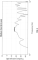
- FIG. 4-6 show examples of how the feedback estimate in the frequency domain looks with three different vent channel openings.
- the vent channel size is equivalent to a ⁇ 5.0 mm standard 19 mm long vent channel, and here the average feedback estimate from 2.8-3.2 kHz is around -6 dB.
- the vent channel size is equivalent to a ⁇ 2.4 mm standard 19 mm vent channel, and here the average feedback estimate from 2.8-3.2 kHz is around -17 dB.
- the vent channel is closed and the feedback estimate is around -24 dB in the same frequency range around the 3 kHz peak. When the vent channel is closed there would still be feedback present from the potential leakage between the earpiece and the ear canal wall. The accuracy of the feedback estimate would usually also drop at lower levels of feedback.
- FIG. 7 shows one way to improve feedback estimation.
- a solution similar to the one illustrated in FIG. 3 is presented, where additionally the input signal (IS) is provided to the valve control unit (VC).
- IS input signal
- VC valve control unit
- an additional input from the microphone(s) can be delivered to the vent channel control unit (VC), which may be configured to only allow to change the vent channel size when the acoustical situation is acceptable, e.g. when an external sound pressure level is below a certain threshold, and/or when no pure tones are present in the relevant frequency range.
- FIG. 8 shows yet another implementation of the present disclosure.
- a hearing device HD
- a hearing device comprising two microphones (mic), a beamformer (BF), a hearing loss compensation unit (HLC), an own voice detector (OVD), the feedback estimator unit (FBest), the valve control unit (VC), the vent channel with the valve (valve) and the loudspeaker (speaker).
- Input signals are delivered from the microphones (mic) to the beamformer (BF), which delivers a combined (spatially filtered) signal based on the microphone signals to the hearing loss compensation unit (HLC).
- the hearing loss compensation unit (HLC) is configured to adjust (compensate for a hearing impairment) the spatially filtered signal and to deliver the compensated signal (OS) to the loudspeaker (speaker).
- the feedback estimator unit (FBest) is configured to receive input signals (IS) from the microphones and (compensated) output signal (OS) from the hearing loss compensation unit (HLC), and the feedback estimator unit (FBest) is configured to provide a first control signal (CS1) in the same manner as in the figures 1-3 .
- a further control signal (CS2) is also provided by the hearing loss compensation unit (HLC), which is configured to provide the signal on a basis of, for example, a set gain (e.g. a requested gain according to the needs of the user in view of a hearing impairment). When gain is lowered, it may enable to open the valve more.
- the own voice detection unit (OVD) is configured to provide another control signal (CS3) on a basis of received signal from the hearing loss compensation unit (HLC). In the case when a user is talking and the valve is completely closed, the user will typically experience an occlusion effect, which will lower a comfort of the user.
- HEC hearing loss compensation unit
- Control signals may also be delivered from external sources such as an external device (ED) or a fitting software system (FS).
- ED external device
- FS fitting software system
- the external device such as a telephone, smartphone, television, or a computer
- the user may like to attenuate external sounds and closing the valve may be a desired action (e.g. automatically initiated, or initiated via a user interface, e.g. implemented on an external device, e.g. the device from which the sound is streamed, e.g. a smartphone or a similar device).
- a hearing care professional may wish to limit the valve performance by limiting how close or how open it can be, or both.
- the limits may vary in dependence of a level of a user's hearing loss, the hearing aid type, a dome type and/or an ear mould, or of a hearing loss type or of user preferences.
- control signals (CS) from the embodiment provided in FIG. 8 must be implemented in a hearing device. It should also be noted that some control signals (CS) might override other control signals (CS). For example, a valve operating limit set by a HCP might override feedback estimator unit (FBest) control signal (CS). In every case priority of each control signal (CS) may be set individually and may be permanent or programable. The priority may e.g. be implemented as weights applied to the individual control signals.
- FBest feedback estimator unit
- valve control signal is determined in one of the two hearing devices of the binaural hearing system and transferred to the other (dependent) hearing device. It may be beneficial because of simpler design of the ⁇ dependent hearing aid'.
- a person having ordinary skill in the art will understand that in a hearing device there are also additional elements needed for proper performance of the hearing device such as a battery or batteries, a power supply or conversion unit, or an anti-feedback unit.
- additional elements such as a battery or batteries, a power supply or conversion unit, or an anti-feedback unit.
- other, additional features/units such as programing interface to modify a processor' s program, a wireless interface such as Wi-Fi, Bluetooth or other suitable interfaces.
- Some of the mentioned units/features are not shown in figures in order to keep figures as simple and easy to understand as possible. For the same reason there is only, for example, only one microphone in some of the figures - a person skilled in the art will understand that more than one microphone or speaker may be used.
- control signal may be understood as analog or digital data, signal or indication (e.g. binary, e.g. true/false) that some condition has been met.
- indication e.g. binary, e.g. true/false
- a person skilled in the art will understand that a nature of the control signal may be different with each unit configured to generate such signal and in different implementations.
- valve is configured to open and close the vent formed by a vent channel through which sound may escape.
- the valve may be configured and incorporated into the hearing aid in a plurality of different ways, wherein some exemplary embodiments will be described in the following. It should be noted that all of the mentioned embodiments of a valve as described in the following may be controlled by the valve control of the hearing aid as described in previous sections. Furthermore, additional embodiments falling within the scope of these examples may be contemplated.
- Figures 9 and 10 show a first valve embodiment, namely a ball valve.
- Figure 9 shows the ball valve and figure 10 shows a cross-section of the ball valve.
- the vent comprises two portions - first vent portion 101 and second vent portion 102, which are separated from each other with a valve 100.
- the valve comprises a valve housing 103, which comprises inner space 105. Within this inner surface 105 a rotatable ball 104 is placed. The ball 104 is being able to rotate about a ball rotation axis 106.
- the ball 104 comprises a passage 104a which is a hallow canal extending through the ball 104.
- the housing 103 of the valve 100 comprising a first opening 103a and a second opening 103b, wherein the first opening 103a connects the passage 104a with the first vent portion 101 and the second opening 103b with the second vent portion 102.
- the ball 104 at a first rotation position where the passage 103a is perpendicular to a vent axis, blocks a connection between the first opening 103a and the second opening 103b, and at a second position, where the passage 103a is align with the valve axis, the passage 104a connects the first opening 103a and the second opening 103b defining a passage axis.
- the valve 100 comprises an actuator configured to rotate the ball 104.
- the valve control unit VC is configured to control and drive the actuator.
- the first rotation position may be desired when a user of a hearing device comprising such valve would like to stream sound directly to the hearing device.
- a user decides to speak the valve 100 should be open, so an occlusion effect would not appear.
- the hearing device comprising the valve 100 would be able to quickly change from being closed, in the first rotation position, to being open, in the second rotation position, when the necessity arises such as the user starts speaking or other mention hereinbefore.
- the ball 104 has a spherical shape and the passage 104a has a circular cross-section shape. It should be noted that the ball 104 may have any axially symmetrical shape, such as a cylindrical shape or ellipsoid shape. Also the passage 104a may have any shape - it may have the cross-section of any shape and also the passage may be curved, straight or in any spatial shape which allows connection of the first opening 103a and the second opening 103b.
- first rotation position does not have to fully block the connection between the first opening 103a and the second opening 103b
- second rotation position does not have to fully connect the first opening 103a and the second opening 103b. It is important that the valve may provide a possibility to limit a sound passing through.
- the specific lower (the first rotation position) and upper (the second rotation position) limit is to be defined in every single hearing device.
- the valve 100 may comprise at least one, preferably two pins.
- This pin(s) provides a pivot bearing along the ball rotation axis 106. This bearing is provided between the inner space 105 and the ball 104.
- This pin(s) may be a part of the ball 104, the inner surface 105 or be third, separate part.
- the ball 104 may comprise slot(s) 110, as shown in figure 11 .
- the ball 104 may be a magnet.
- the valve actuator may comprise a first electromagnetic coil 107 and a second electromagnetic coil 108, both wounded around the housing 103 such that when the first electromagnetic coil 107 is driven by the valve control unit VC and the second electromagnetic coil 108 is not driven, the ball 104 takes the first rotation position, and if the second electromagnetic coil 108 is driven and the first electromagnetic coil 107 is not driven, the ball 104 takes the second rotation position.
- ball 104 being the magnet, aligns with the magnetic field created by the first electromagnetic coli 107 or the second electromagnetic coil 108. In this case the ball 104 acts as a rotor in an electrical motor.
- the ball 104 takes a third rotation position between the first rotation position and the second rotation position corresponding to a proportion of magnetic fields generated by the first electromagnetic coil 107 and the second electromagnetic coil 108.
- Figure 11 shows a ball 104 in more details.
- This figure shows a plane 109 separating north and south magnetic poles N, S of the ball 104.
- This plane is angled by 45 degrees with respect to a passage 104a axis about the ball rotation axis 106.
- This arrangement of magnetic poles allows to wound the first electromagnetic coil 107 and the second electromagnetic coil 108 in convenient and easy to assembly place. It should be understand that with different valve design it may be beneficial to arrange differently how those magnetic poles are positions on a ball 104.
- the ball 104 may be in a frictional contact with the inner space 105 such that, if the actuator is not driven, preferably when the first electromagnetic coil 107 is not driven and the second electromagnetic coil 108 is not driven, a rotation position of the ball 104 is maintained.
- valve does not need constant power consumption.
- the first electromagnetic coil 107 and the second electromagnetic coli 108 do not have to be powered.
- a torque between the ball 104 and the inner surface 105 is high enough to keep the ball 105 in the new rotation position.
- an air flow passing through the valve 100 will have small volume and speed thus the forces acting on a ball 104 will be small and the torque between the ball 104 and the inner surface 105 will be sufficient to keep the ball in a desired rotation position.
- the passage 104a axis may go through a ball 104 geometric center. This arrangement, with the passage 104a being straight canal, provides the least resistance to air passing through the valve 100 and enables the biggest possible passage 104a in this type of the valve 100.
- FIGS 12A , 12B, 12C show a second valve embodiment, namely a cradle valve.
- the vent comprises a first vent portion 201 and a second vent portion 202 separated by the valve 200.
- a valve housing 203 may have an opening 204 connecting the first vent portion 201 with the second vent portion 202.
- the valve 200 comprises a lid unit 205 rotatable about a lid unit rotation axis 206.
- the lid unit 205 comprises a cylinder side surface section 205a and a supporting section 205b extending toward the lid unit rotation axis 206.
- the lid unit rotation axis 206 is in a center of an imaginary cylinder which comprises the side surface section 205a.
- the valve 200 comprises an actuator configured to rotate the lid unit 205, and the valve control unit VC is configured to control and drive the actuator.
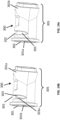
- Figure 12A shows the cradle valve in an open position, wherein the lid unit 205 is in the first position, which allows air to pass through the valve 200 with the least resistance caused by the cylinder side surface section 205a.
- Figure 12B shows the cradle valve in partially closed position, wherein the lid unit 205 is in an intermediate position which creates a resistance to an air passing through. This resistance depends on the lid unit 205 position and may be adjusted in particular situations, such as when the environment sound is getting louder and a reduction of a sound reaching a user's tympanic membrane is desired.
- Figure 12B shows shows the cradle valve in a closed position, wherein the lid unit 205 is in the second position, which blocks the air from passing through the valve 200.
- an inner wall 207 of the valve 200 is formed to correspond to a shape of the cylinder side surface section 205a of the lid unit 205.
- This inner wall shape allows to minimalize the resistance caused by the lid unit 205 while being in the first position. This solution allows the lid unit 205 to be partially covered by the inner wall 207 thereby reducing the resistance.
- the inner wall 207 is in a frictional contact with the lid unit 205 cylinder side surface section 205a. This feature allows to reduce a power consumption by enabling the actuator to be turned off after a desired position of the lid unit 207 was achieved. The frictional contact will be able to prevent undesired movement of the lid unit 206 caused by an air movement.
- valve 200 comprises a pin providing a pivot bearing between the valve 200 and the supporting section 205b of the lid unit 205.
- valve actuator comprises an electrical motor, preferably a stick slip motor including a piezo element, and a movement transmission element 208 connected to the motor.
- valve control unit VC is configured to drive the piezo element based on the control signal CS to cause the lid unit 205 to approach one of the first rotation position, the second rotation position, and a third rotation position between the first rotation position and the second rotation position by an alternating extension and contraction of the piezo element.
- the extension of the stick slip motor is slower than the contraction or the contraction is slower than the extension.
- FIGS 13A-13C and 14A-14C show a third valve embodiment, namely a piston valve.
- the vent 301 may be configured as part of a speaker unit 304, but it also may be a separate part, of the hearing device.
- the speaker unit 304 comprises a snout 305 within which the vent 301 extends in a longitudinal direction of the snout 305.
- the vent 301 is configured as a bore and the valve 300 is configured to be arranged within said bore.
- the valve 300 may comprise a piston unit 303 movable along the longitudinal axis of the vent 301 portion.
- a cross section of the piston unit 303, perpendicular to the longitudinal axis of the vent 301 corresponds to a bore cross section of the bore to thereby allow the piston unit 303 to slidably fit into the bore of the vent 301.
- the piston unit 303 being able to occlude, at least partly and/or in full, the vent 301 by moving inside the vent 301 from a distal end 301a, positioned near an ear canal entrance, of the vent 301 to a proximal end 301b, positioned near to the tympanic membrane.
- the valve 300 comprises an actuator configured to move the piston unit 303.
- an end surface of the piston unit 303 may have a curved surface 303a.
- the curved surface 303a may be any non-planar surface which allows to better control how open or close the valve 300 is.
- planar end surface of the piston unit 303 there is very short distance between valve 300 being fully open and fully closed.
- curved surface 303a it is possible to extend this distance between valve 300 being fully open and fully closed. It is also possible to define this surface in such manner that a function of closing the valve 300, with relation to the position of the piston unit 303, is a linear function, logarithmic function etc.
- the snout 305 may comprise a slit opening.
- One side of the slit opening is curved so as to form the substantially v-shaped cut-out 302 in the snout 305.
- the piston unit 303 is configured to at least partly and/or in full to cover the cut-out.
- the purpose of the slit opening is similar to the curved surface 303a, that is a better control of the valve 300.
- the shape of the slit opening may also be defined such that, alone or in the combination with the curved surface 303a, may provide a specific function of closing the valve 300, with relation to the position of the piston unit 303.
- valve 300 may be configured to be moved into at least a closed position, and open position and an intermediate position.
- the valve 300 occludes the vent in full, in an intermediate position, the valve 300 at least partly occludes the vent, and in an open position, the valve 300 leaves the vent open.
- FIG 13a the valve 300 is shown in fully open position.
- the piston 303 is in the most distant position with respect to the proximal end 301b and a opening or a v-shaped cut-out 302 have the biggest size providing the least resistance to air passing through the valve 300.
- the piston 303 is in intermediate position.
- the opening is partially closed limiting the amount of an air and a sound passing through.
- the piston 303 is in the closest position with respect to the proximal end 301b. The opening is fully covered by the piston 303 and the valve 300 is closed.
- the curved end surface 303a of said piston unit 303 is configured to provide a smooth transition of air passing into the vent 301 and escaping through the vent 301.
- valve 300 comprises a piston guide 306 configured to be actuated by the control unit, wherein upon actuation by the control unit, the valve piston guide 306 acts on the piston unit 303 so as to force the piston unit 303 into a closed position, an open position or a partly open position.
- piston guide 306 of this shape is merely an example and the person skilled in the art would came up with other actuators types and different parts shape that are configured to provide linear movement of the piston 303.
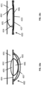
- FIGS 17A and 17B show a fourth valve embodiment, namely a membrane valve.
- the valve 400 may comprise a membrane 402 configured to open the vent 401, in a membrane shrunken state, or close the vent 401, in a membrane extended state.
- the membrane 402 is configured to extend and shrink within the vent 401.
- the membrane 402 is an actuator 407 and/or the valve 400 comprises an actuator 407 for controlling the membrane 402.
- the membrane 402 is an actuator 407 or an actuator 407 is configured to act on a membrane 402. It is also possible to have more than one membrane 402 in one embodiment and more than one actuator 407 in the valve 400.
- the valve 400 may comprise a volume defined by an inner volume 405 and an outer volume 406.
- the inner volume 405 is determined by the membrane 402 and a valve wall 404
- the outer volume 406 is determined by an outer membrane 403 and the valve wall 404.
- the volume 405 is filled with a fluid and the actuator 407 is configured to control the membrane 402 to change the outer volume 406 and push fluid into the inner volume 405.
- This volume acts like a balloon which is pushed on one side. By controlling force applied it is possible to adjust how open or closed the valve 400 is.
- this solution may be achieve by inserting a balloon-like, field with liquid and sealed membrane 402, 403, which is placed in the opening of a valve wall.
- the opening should, preferably, be rounded and do not have corners. Examples of preferred shapes are an ellipsis or a circle.
- the other possibility is to attach both membranes 402, 403 independently to the valve wall, one membrane 402 to one side of the valve wall and other membrane 403 to other side of the valve wall, and filling created volume with a liquid.
- membrane 402 may be made of a polymeric material such as rubber. In this case this membrane, in fully closed state, would provide additional sealing.
- the valve 400 comprises the actuator 407.
- the actuator 407 is not a membrane 402, 403, but it is a separate piece. It should be however noted that more than one actuator may be present in the valve 400.
- This actuator 407 may be made of an artificial muscle or a piezoelectric material. It should be noted that the person skilled in the art would know other actuators suitable for this application.
- the actuator 407 is controlled and driven electrically, preferably is controlled and driven by a voltage.
- the actuator 407 is slidably connected to a ventilation valve wall and preferably one point of the actuator is fixed to the vent wall. To allow the actuator to bend or to move it may be necessary to provide a hinge or slidably connection to the valve wall.
- the fluid is a liquid. Due to the fact that liquids may be considered, in application like this, as incompressible, it may be beneficial to fill the volume with a liquid. This may result in smaller distances needed to fully close the valve 400. It would also make possible to determine, with greater precision, how open or closed the valve is based on a current actuator position. If the liquid is a gas then pushing membrane 403 may not result in similar and repeatable extension of the membrane 402. The liquid may help solving at least one of this problems.
- connection or “coupled” as used herein may include wirelessly connected or coupled.
- the term “and/or” includes any and all combinations of one or more of the associated listed items. The steps of any disclosed method is not limited to the exact order stated herein, unless expressly stated otherwise.
Landscapes
- Engineering & Computer Science (AREA)
- Physics & Mathematics (AREA)
- Acoustics & Sound (AREA)
- Signal Processing (AREA)
- Health & Medical Sciences (AREA)
- General Health & Medical Sciences (AREA)
- Neurosurgery (AREA)
- Otolaryngology (AREA)
- Manufacturing & Machinery (AREA)
- Circuit For Audible Band Transducer (AREA)
- Headphones And Earphones (AREA)
- Details Of Audible-Bandwidth Transducers (AREA)
Claims (16)
- Dispositif auditif conçu pour être situé entièrement ou partiellement dans ou au niveau d'une oreille d'un utilisateur, le dispositif auditif (HD) comprenant :au moins un microphone (mic) configuré pour fournir un signal d'entrée (IS) représentant le son,un processeur (DSP) configuré pour traiter le signal d'entrée (IS) et fournir un signal traité (OS),au moins un haut-parleur (speaker) configuré pour recevoir le signal traité (OS) du processeur (DSP) et pour fournir un signal acoustique basé sur le signal traité (OS) à l'oreille d'un utilisateur,un écouteur comprenantun évent (vent), etune valve commandable électriquement (valve) configurée pour commander l'état de l'évent (vent), etune unité de commande de valve (VC) configurée pour recevoir un ou plusieurs signaux de commande (CS) en fonction d'une situation auditive actuelle du dispositif auditif (HD),dans lequel le dispositif auditif comprend une unité d'estimation de rétroaction (FBest) et au moins un de l'un ou plusieurs signaux de commande (CS) est obtenu en fonction d'une sortie de l'unité d'estimation de rétroaction (FBest), dans lequel l'unité de commande de valve (VC) est configurée pour ajuster la valve commandable électriquement (valve) sur la base du signal de sortie provenant de l'unité d'estimation de rétroaction (FBest) pour permettre à l'évent (vent) d'être dans un état ouvert, dans un état fermé et dans un ou plusieurs états compris entre les deux, dans lequell'évent comprend une première partie d'évent (101) et une seconde partie d'évent (102) séparées par la valve (100), la valve (100) comprend un boîtier de valve (103), le boîtier de valve (103) ayant un espace intérieur (105) comprenant une bille rotative (104), la bille (104) pouvant tourner autour d'un axe de rotation de bille (106), dans lequel la bille (104) comprend un passage (104a),dans lequel une première ouverture (103a) dudit boîtier de valve (103) relie le passage (104a) à la première partie d'évent (101), et une seconde ouverture (103b) dudit boîtier de valve (103) relie le passage à la seconde partie d'évent (102),et dans lequeldans une première position de rotation de la bille (104), la bille bloque une connexion entre la première ouverture (103a) et la seconde ouverture (103b), et dans une seconde position de rotation de la bille (104), le passage (104a) relie la première ouverture (103a) et la seconde ouverture (103b) et définissant un axe de passage,dans lequel en outre la valve (100) comprend un actionneur configuré pour faire tourner la bille (104), et l'unité de commande de valve (VC) est configurée pour commander et entraîner l'actionneur.
- Dispositif auditif selon la revendication 1, dans lequel l'au moins un microphone (mic) est configuré pour délivrer le signal d'entrée (IS) sous la forme d'un signal de commande (CS) à l'unité de commande de valve (VC).
- Dispositif auditif selon l'une quelconque des revendications 1 à 2, comprenant un détecteur de propre voix (OVD) configuré pour détecter une voix de l'utilisateur, et dans lequel au moins un de l'un ou plusieurs signaux de commande (CS) est obtenu en fonction de la sortie du détecteur de propre voix (OVD).
- Dispositif auditif selon l'une quelconque des revendications 1 à 3, dans lequel au moins un de l'un ou plusieurs signaux de commande (CS) est obtenu en fonction d'une entrée vers le dispositif auditif (HD) via un dispositif externe (ED), dans lequel le l'entrée est destinée à une diffusion audio en continu ou à un appel téléphonique.
- Dispositif auditif selon l'une quelconque des revendications 1 à 4, dans lequel le dispositif auditif (HD) est ou comprend une prothèse auditive.
- Dispositif auditif selon l'une quelconque des revendications 1 à 5, dans lequel le processeur (DSP) comprend une unité de compensation de perte auditive (HLC) et au moins l'un de l'un ou plusieurs signaux de commande (CS) est obtenu en fonction d'un ensemble de gains dans l'unité de compensation de perte auditive (HLC).
- Dispositif auditif selon l'une quelconque des revendications 1 à 6, dans lequel au moins un de l'un ou plusieurs signaux de commande (CS) est obtenu en fonction d'une perte auditive, d'un type de prothèse auditive et/ou d'un embout auriculaire d'utilisateur.
- Dispositif auditif selon l'une quelconque des revendications 1 à 7, dans lequel l'unité de commande de valve (VC) est configurée pour commander la valve commandable électriquement (valve) afin de garantir que les états plus ouverts et moins ouverts de l'évent (vent) sont définis par des limites supérieure et inférieure définies par un logiciel d'ajustement (FS).
- Dispositif auditif selon l'une quelconque des revendications 1 à 8, dans lequel l'unité de commande de valve (VC) est configurée pour déterminer si la valve (valve) est ouverte, partiellement ouverte ou fermée sur la base d'un signal provenant de l'unité d'estimation de rétroaction (FBest).
- Dispositif auditif selon la revendication 9, dans lequel l'un ou plusieurs signaux de commande (CS) provenant de l'unité d'estimation de rétroaction (FBest) sont une réponse impulsionnelle du trajet de rétroaction.
- Dispositif auditif selon la revendication 10, dans lequel l'unité de commande de valve (VC) est configurée pour appliquer une transformation de Fourier rapide à la réponse impulsionnelle pour fournir une réponse en fréquence du trajet de rétroaction.
- Dispositif auditif selon la revendication 11, dans lequel l'unité de commande de valve (VC) est configurée pour commander l'évent (vent) en fonction des valeurs de la réponse en fréquence du trajet de rétroaction à une ou plusieurs fréquences ou plages de fréquences sélectionnées.
- Dispositif auditif selon l'une quelconque des revendications 1 à 12, dans lequel l'unité de commande de valve (VC) est configurée pour ajuster la valve (valve) de manière synchrone avec un autre appareil auditif d'utilisateur.
- Dispositif auditif selon l'une quelconque des revendications 1 à 13, dans lequel au moins l'un de l'un ou plusieurs signaux de commande (CS) est obtenu en fonction d'une estimation de niveau d'un environnement acoustique actuel de l'appareil auditif (HD).
- Dispositif auditif selon l'une quelconque des revendications 1 à 13, dans lequel la valve commandable électriquement (valve) est située dans ou fait partie de l'évent (vent).
- Dispositif auditif selon l'une quelconque des revendications 1 à 15, dans lequell'évent (301) est conçu comme faisant partie d'une unité de haut-parleur (304) dudit appareil auditif, dans lequel ladite unité de haut-parleur (304) comprend un bec (305),dans lequel, à l'intérieur dudit bec (305), ledit évent (301) s'étend dans une direction longitudinale du bec (305) et est conçu comme un alésage, dans lequel la valve (300) est conçue pour être disposée à l'intérieur dudit alésage.
Priority Applications (1)
| Application Number | Priority Date | Filing Date | Title |
|---|---|---|---|
| EP24200841.5A EP4472240A3 (fr) | 2019-02-07 | 2020-01-06 | Dispositif auditif comprenant un évent réglable |
Applications Claiming Priority (1)
| Application Number | Priority Date | Filing Date | Title |
|---|---|---|---|
| EP19155935 | 2019-02-07 |
Related Child Applications (3)
| Application Number | Title | Priority Date | Filing Date |
|---|---|---|---|
| EP24200841.5A Division-Into EP4472240A3 (fr) | 2019-02-07 | 2020-01-06 | Dispositif auditif comprenant un évent réglable |
| EP24200841.5A Division EP4472240A3 (fr) | 2019-02-07 | 2020-01-06 | Dispositif auditif comprenant un évent réglable |
| EP24200841.5A Previously-Filed-Application EP4472240A3 (fr) | 2019-02-07 | 2020-01-06 | Dispositif auditif comprenant un évent réglable |
Publications (3)
| Publication Number | Publication Date |
|---|---|
| EP3694227A1 EP3694227A1 (fr) | 2020-08-12 |
| EP3694227B1 true EP3694227B1 (fr) | 2024-10-30 |
| EP3694227C0 EP3694227C0 (fr) | 2024-10-30 |
Family
ID=65363135
Family Applications (2)
| Application Number | Title | Priority Date | Filing Date |
|---|---|---|---|
| EP20150302.6A Active EP3694227B1 (fr) | 2019-02-07 | 2020-01-06 | Dispositif auditif comprenant un évent réglable |
| EP24200841.5A Pending EP4472240A3 (fr) | 2019-02-07 | 2020-01-06 | Dispositif auditif comprenant un évent réglable |
Family Applications After (1)
| Application Number | Title | Priority Date | Filing Date |
|---|---|---|---|
| EP24200841.5A Pending EP4472240A3 (fr) | 2019-02-07 | 2020-01-06 | Dispositif auditif comprenant un évent réglable |
Country Status (3)
| Country | Link |
|---|---|
| US (2) | US11228848B2 (fr) |
| EP (2) | EP3694227B1 (fr) |
| CN (2) | CN118175493A (fr) |
Families Citing this family (20)
| Publication number | Priority date | Publication date | Assignee | Title |
|---|---|---|---|---|
| WO2020121608A1 (fr) * | 2018-12-14 | 2020-06-18 | ソニー株式会社 | Dispositif et système acoustique |
| NL2024731B1 (en) * | 2020-01-22 | 2021-09-09 | Sonova Ag | Acoustic device with deformable shape as valve |
| TWI778372B (zh) * | 2020-06-12 | 2022-09-21 | 研能科技股份有限公司 | 耳機 |
| NL2026507B1 (en) * | 2020-09-21 | 2022-05-24 | Sonion Nederland Bv | Hearing device and method to provide such a hearing device |
| DK181160B1 (en) | 2020-11-30 | 2023-03-09 | Gn Hearing As | Hearing device earpiece having intermediate module |
| DE102021200635A1 (de) * | 2021-01-25 | 2022-07-28 | Sivantos Pte. Ltd. | Verfahren zum Betrieb eines Hörgeräts, Hörgerät und Computerprogrammprodukt |
| EP4236353A4 (fr) * | 2021-02-10 | 2024-08-21 | Samsung Electronics Co., Ltd. | Dispositif électronique comprenant une structure d'ouverture et de fermeture |
| EP4044623A1 (fr) * | 2021-02-11 | 2022-08-17 | Sonova AG | Dispositif auditif comprenant un évent et une soupape acoustique |
| NL2027562B1 (en) * | 2021-02-16 | 2022-09-14 | Sonion Nederland Bv | Sound channel, portable audio device comprising such a sound channel and method of operating such a sound channel |
| US12200425B2 (en) | 2021-05-06 | 2025-01-14 | Gn Hearing A/S | Hearing device comprising a receiver module comprising a vent having a vent valve device |
| DK202170278A1 (en) * | 2021-05-28 | 2022-12-06 | Gn Hearing 2 As | A hearing device comprising a sound path component |
| US12081934B2 (en) * | 2021-09-17 | 2024-09-03 | Apple Inc. | Dynamic valve for an electronic device |
| US12267641B2 (en) * | 2021-11-29 | 2025-04-01 | Apple Inc. | Electroosmotic flow valve for an electronic device |
| WO2023147858A1 (fr) * | 2022-02-03 | 2023-08-10 | Huawei Technologies Co., Ltd. | Écouteur |
| DE102022202713B3 (de) | 2022-03-21 | 2023-09-14 | Sivantos Pte. Ltd. | Verfahren zum Betrieb eines Hörgerätes und Hörgerät |
| CN114615584B (zh) * | 2022-03-22 | 2025-08-19 | 听智慧科技(深圳)有限公司 | 入耳式可穿戴设备 |
| WO2023210452A1 (fr) * | 2022-04-25 | 2023-11-02 | ソニーグループ株式会社 | Dispositif auditif, écouteur, programme et procédé de commande |
| JP2023181809A (ja) * | 2022-06-13 | 2023-12-25 | パナソニックIpマネジメント株式会社 | イヤフォン、音響制御方法およびプログラム |
| JP2023181811A (ja) * | 2022-06-13 | 2023-12-25 | パナソニックIpマネジメント株式会社 | イヤフォン、イヤフォン制御方法およびプログラム |
| JP2025096047A (ja) * | 2023-12-15 | 2025-06-26 | ソニーグループ株式会社 | 補聴器、制御方法及びプログラム |
Family Cites Families (15)
| Publication number | Priority date | Publication date | Assignee | Title |
|---|---|---|---|---|
| DE2435272A1 (de) * | 1974-07-23 | 1976-02-05 | Westfaelische Metall Industrie | Absperrvorrichtung fuer den entlueftungskanal einer giessform |
| US7401680B2 (en) * | 2004-12-23 | 2008-07-22 | Phonak Ag | Hearing protection earplug and use of the same |
| DK1708544T3 (en) * | 2005-03-29 | 2015-10-19 | Oticon As | System and method for measuring ventilation effects in a hearing aid |
| EP1931172B1 (fr) * | 2006-12-01 | 2009-07-01 | Siemens Audiologische Technik GmbH | Prothèse auditive avec suppression du bruit et procédé correspondant |
| EP2438765A1 (fr) * | 2009-06-02 | 2012-04-11 | Koninklijke Philips Electronics N.V. | Agencement d'ecouteur et son procede de fonctionnement |
| WO2013138722A1 (fr) * | 2012-03-16 | 2013-09-19 | Thomson Reuters Global Resources | Système et procédé de vérification de conformité automatisée |
| EP2835987B1 (fr) * | 2013-12-06 | 2017-08-30 | Oticon A/s | Prothèse auditive à évent régulable |
| DK2947898T3 (da) * | 2014-05-20 | 2019-05-13 | Oticon As | Høreanordning |
| GB201500554D0 (en) * | 2015-01-14 | 2015-02-25 | Expro North Sea Ltd | Ball valve |
| CN108136388A (zh) * | 2015-04-30 | 2018-06-08 | 奥菲迪亚有限公司 | 微流阀和装置 |
| EP3182721A1 (fr) * | 2015-12-15 | 2017-06-21 | Sony Mobile Communications, Inc. | Contrôle d'expérience own-voice de locuteur avec oreille occultée |
| EP3324644B1 (fr) * | 2016-11-17 | 2020-11-04 | Oticon A/s | Dispositif auditif sans fil avec stabilisateur entre tragus et anti-tragus |
| US10142745B2 (en) * | 2016-11-24 | 2018-11-27 | Oticon A/S | Hearing device comprising an own voice detector |
| US11343620B2 (en) * | 2017-12-21 | 2022-05-24 | Widex A/S | Method of operating a hearing aid system and a hearing aid system |
| DE202018107151U1 (de) * | 2018-01-08 | 2019-01-15 | Knowles Electronics, Llc | Audiovorrichtung mit Ventilzustandsverwaltung |
-
2020
- 2020-01-06 EP EP20150302.6A patent/EP3694227B1/fr active Active
- 2020-01-06 EP EP24200841.5A patent/EP4472240A3/fr active Pending
- 2020-01-24 CN CN202410299401.5A patent/CN118175493A/zh active Pending
- 2020-01-24 CN CN202010077228.6A patent/CN111541980B/zh active Active
- 2020-01-27 US US16/773,483 patent/US11228848B2/en active Active
-
2021
- 2021-12-06 US US17/543,269 patent/US12022260B2/en active Active
Also Published As
| Publication number | Publication date |
|---|---|
| CN111541980A (zh) | 2020-08-14 |
| US20220095058A1 (en) | 2022-03-24 |
| US20200260197A1 (en) | 2020-08-13 |
| CN111541980B (zh) | 2024-04-19 |
| EP3694227C0 (fr) | 2024-10-30 |
| US11228848B2 (en) | 2022-01-18 |
| US12022260B2 (en) | 2024-06-25 |
| EP3694227A1 (fr) | 2020-08-12 |
| CN118175493A (zh) | 2024-06-11 |
| EP4472240A3 (fr) | 2025-01-22 |
| EP4472240A2 (fr) | 2024-12-04 |
| US20240292159A1 (en) | 2024-08-29 |
Similar Documents
| Publication | Publication Date | Title |
|---|---|---|
| EP3694227B1 (fr) | Dispositif auditif comprenant un évent réglable | |
| EP2835987B1 (fr) | Prothèse auditive à évent régulable | |
| US10820119B2 (en) | Hearing device comprising a feedback reduction system | |
| EP3637789B1 (fr) | Appareil auditif à chambres connectées acoustiquement et son procédé de fonctionnement | |
| EP3685592B1 (fr) | Dispositif de communication avec joint acoustique et évent | |
| EP3051844B1 (fr) | Système auditif binauriculaire | |
| EP3185589A1 (fr) | Dispositif auditif comprenant un système de commande de microphone | |
| EP3799444B1 (fr) | Prothèse auditive comportant un système de microphone directionnel | |
| US20200322736A1 (en) | Hearing device comprising a microphone adapted to be located at or in the ear canal of a user | |
| US11457318B2 (en) | Hearing device configured for audio classification comprising an active vent, and method of its operation | |
| EP3185588A1 (fr) | Dispositif auditif comprenant un détecteur de rétroaction | |
| EP3637799B1 (fr) | Dispositif auditif comprenant un boîtier avec un passage d'aération | |
| US9936315B2 (en) | Method of fitting a hearing device to a user, a fitting system for a hearing device and a hearing device | |
| US11792564B2 (en) | Hearing device comprising a vent and an acoustic valve | |
| EP3249955B1 (fr) | Prothèse auditive configurable comprenant une unité de filtrage à focalisateur et une unité d' amplification | |
| US12621614B2 (en) | Hearing device comprising an adjustable vent |
Legal Events
| Date | Code | Title | Description |
|---|---|---|---|
| PUAI | Public reference made under article 153(3) epc to a published international application that has entered the european phase |
Free format text: ORIGINAL CODE: 0009012 |
|
| STAA | Information on the status of an ep patent application or granted ep patent |
Free format text: STATUS: THE APPLICATION HAS BEEN PUBLISHED |
|
| AK | Designated contracting states |
Kind code of ref document: A1 Designated state(s): AL AT BE BG CH CY CZ DE DK EE ES FI FR GB GR HR HU IE IS IT LI LT LU LV MC MK MT NL NO PL PT RO RS SE SI SK SM TR |
|
| AX | Request for extension of the european patent |
Extension state: BA ME |
|
| STAA | Information on the status of an ep patent application or granted ep patent |
Free format text: STATUS: REQUEST FOR EXAMINATION WAS MADE |
|
| 17P | Request for examination filed |
Effective date: 20210212 |
|
| RBV | Designated contracting states (corrected) |
Designated state(s): AL AT BE BG CH CY CZ DE DK EE ES FI FR GB GR HR HU IE IS IT LI LT LU LV MC MK MT NL NO PL PT RO RS SE SI SK SM TR |
|
| STAA | Information on the status of an ep patent application or granted ep patent |
Free format text: STATUS: EXAMINATION IS IN PROGRESS |
|
| RIC1 | Information provided on ipc code assigned before grant |
Ipc: H04R 25/00 20060101AFI20220923BHEP |
|
| 17Q | First examination report despatched |
Effective date: 20221011 |
|
| GRAP | Despatch of communication of intention to grant a patent |
Free format text: ORIGINAL CODE: EPIDOSNIGR1 |
|
| STAA | Information on the status of an ep patent application or granted ep patent |
Free format text: STATUS: GRANT OF PATENT IS INTENDED |
|
| INTG | Intention to grant announced |
Effective date: 20240522 |
|
| GRAS | Grant fee paid |
Free format text: ORIGINAL CODE: EPIDOSNIGR3 |
|
| GRAA | (expected) grant |
Free format text: ORIGINAL CODE: 0009210 |
|
| STAA | Information on the status of an ep patent application or granted ep patent |
Free format text: STATUS: THE PATENT HAS BEEN GRANTED |
|
| AK | Designated contracting states |
Kind code of ref document: B1 Designated state(s): AL AT BE BG CH CY CZ DE DK EE ES FI FR GB GR HR HU IE IS IT LI LT LU LV MC MK MT NL NO PL PT RO RS SE SI SK SM TR |
|
| REG | Reference to a national code |
Ref country code: GB Ref legal event code: FG4D |
|
| REG | Reference to a national code |
Ref country code: CH Ref legal event code: EP |
|
| REG | Reference to a national code |
Ref country code: DE Ref legal event code: R096 Ref document number: 602020040129 Country of ref document: DE |
|
| REG | Reference to a national code |
Ref country code: IE Ref legal event code: FG4D |
|
| U01 | Request for unitary effect filed |
Effective date: 20241107 |
|
| U07 | Unitary effect registered |
Designated state(s): AT BE BG DE DK EE FI FR IT LT LU LV MT NL PT RO SE SI Effective date: 20241115 |
|
| U20 | Renewal fee for the european patent with unitary effect paid |
Year of fee payment: 6 Effective date: 20250217 |
|
| PG25 | Lapsed in a contracting state [announced via postgrant information from national office to epo] |
Ref country code: IS Free format text: LAPSE BECAUSE OF FAILURE TO SUBMIT A TRANSLATION OF THE DESCRIPTION OR TO PAY THE FEE WITHIN THE PRESCRIBED TIME-LIMIT Effective date: 20250228 Ref country code: HR Free format text: LAPSE BECAUSE OF FAILURE TO SUBMIT A TRANSLATION OF THE DESCRIPTION OR TO PAY THE FEE WITHIN THE PRESCRIBED TIME-LIMIT Effective date: 20241030 |
|
| PG25 | Lapsed in a contracting state [announced via postgrant information from national office to epo] |
Ref country code: ES Free format text: LAPSE BECAUSE OF FAILURE TO SUBMIT A TRANSLATION OF THE DESCRIPTION OR TO PAY THE FEE WITHIN THE PRESCRIBED TIME-LIMIT Effective date: 20241030 |
|
| PG25 | Lapsed in a contracting state [announced via postgrant information from national office to epo] |
Ref country code: NO Free format text: LAPSE BECAUSE OF FAILURE TO SUBMIT A TRANSLATION OF THE DESCRIPTION OR TO PAY THE FEE WITHIN THE PRESCRIBED TIME-LIMIT Effective date: 20250130 |
|
| PG25 | Lapsed in a contracting state [announced via postgrant information from national office to epo] |
Ref country code: GR Free format text: LAPSE BECAUSE OF FAILURE TO SUBMIT A TRANSLATION OF THE DESCRIPTION OR TO PAY THE FEE WITHIN THE PRESCRIBED TIME-LIMIT Effective date: 20250131 |
|
| PG25 | Lapsed in a contracting state [announced via postgrant information from national office to epo] |
Ref country code: PL Free format text: LAPSE BECAUSE OF FAILURE TO SUBMIT A TRANSLATION OF THE DESCRIPTION OR TO PAY THE FEE WITHIN THE PRESCRIBED TIME-LIMIT Effective date: 20241030 |
|
| PG25 | Lapsed in a contracting state [announced via postgrant information from national office to epo] |
Ref country code: RS Free format text: LAPSE BECAUSE OF FAILURE TO SUBMIT A TRANSLATION OF THE DESCRIPTION OR TO PAY THE FEE WITHIN THE PRESCRIBED TIME-LIMIT Effective date: 20250130 |
|
| PG25 | Lapsed in a contracting state [announced via postgrant information from national office to epo] |
Ref country code: SM Free format text: LAPSE BECAUSE OF FAILURE TO SUBMIT A TRANSLATION OF THE DESCRIPTION OR TO PAY THE FEE WITHIN THE PRESCRIBED TIME-LIMIT Effective date: 20241030 |
|
| PG25 | Lapsed in a contracting state [announced via postgrant information from national office to epo] |
Ref country code: SK Free format text: LAPSE BECAUSE OF FAILURE TO SUBMIT A TRANSLATION OF THE DESCRIPTION OR TO PAY THE FEE WITHIN THE PRESCRIBED TIME-LIMIT Effective date: 20241030 |
|
| PG25 | Lapsed in a contracting state [announced via postgrant information from national office to epo] |
Ref country code: CZ Free format text: LAPSE BECAUSE OF FAILURE TO SUBMIT A TRANSLATION OF THE DESCRIPTION OR TO PAY THE FEE WITHIN THE PRESCRIBED TIME-LIMIT Effective date: 20241030 |
|
| PLBE | No opposition filed within time limit |
Free format text: ORIGINAL CODE: 0009261 |
|
| STAA | Information on the status of an ep patent application or granted ep patent |
Free format text: STATUS: NO OPPOSITION FILED WITHIN TIME LIMIT |
|
| PG25 | Lapsed in a contracting state [announced via postgrant information from national office to epo] |
Ref country code: MC Free format text: LAPSE BECAUSE OF FAILURE TO SUBMIT A TRANSLATION OF THE DESCRIPTION OR TO PAY THE FEE WITHIN THE PRESCRIBED TIME-LIMIT Effective date: 20241030 |
|
| 26N | No opposition filed |
Effective date: 20250731 |
|
| PGFP | Annual fee paid to national office [announced via postgrant information from national office to epo] |
Ref country code: GB Payment date: 20251219 Year of fee payment: 7 |
|
| PG25 | Lapsed in a contracting state [announced via postgrant information from national office to epo] |
Ref country code: IE Free format text: LAPSE BECAUSE OF NON-PAYMENT OF DUE FEES Effective date: 20250106 |
|
| REG | Reference to a national code |
Ref country code: CH Ref legal event code: U11 Free format text: ST27 STATUS EVENT CODE: U-0-0-U10-U11 (AS PROVIDED BY THE NATIONAL OFFICE) Effective date: 20260201 |
|
| U20 | Renewal fee for the european patent with unitary effect paid |
Year of fee payment: 7 Effective date: 20260202 |
|
| PGFP | Annual fee paid to national office [announced via postgrant information from national office to epo] |
Ref country code: CH Payment date: 20260201 Year of fee payment: 7 |