WO2020121608A1 - Dispositif et système acoustique - Google Patents
Dispositif et système acoustique Download PDFInfo
- Publication number
- WO2020121608A1 WO2020121608A1 PCT/JP2019/034286 JP2019034286W WO2020121608A1 WO 2020121608 A1 WO2020121608 A1 WO 2020121608A1 JP 2019034286 W JP2019034286 W JP 2019034286W WO 2020121608 A1 WO2020121608 A1 WO 2020121608A1
- Authority
- WO
- WIPO (PCT)
- Prior art keywords
- sound
- ear
- unit
- opening
- ear canal
- Prior art date
- Legal status (The legal status is an assumption and is not a legal conclusion. Google has not performed a legal analysis and makes no representation as to the accuracy of the status listed.)
- Ceased
Links
Images


















Classifications
-
- H—ELECTRICITY
- H04—ELECTRIC COMMUNICATION TECHNIQUE
- H04R—LOUDSPEAKERS, MICROPHONES, GRAMOPHONE PICK-UPS OR LIKE ACOUSTIC ELECTROMECHANICAL TRANSDUCERS; ELECTRIC HEARING AIDS; PUBLIC ADDRESS SYSTEMS
- H04R1/00—Details of transducers, loudspeakers or microphones
- H04R1/10—Earpieces; Attachments therefor ; Earphones; Monophonic headphones
- H04R1/1016—Earpieces of the intra-aural type
-
- G—PHYSICS
- G10—MUSICAL INSTRUMENTS; ACOUSTICS
- G10K—SOUND-PRODUCING DEVICES; METHODS OR DEVICES FOR PROTECTING AGAINST, OR FOR DAMPING, NOISE OR OTHER ACOUSTIC WAVES IN GENERAL; ACOUSTICS NOT OTHERWISE PROVIDED FOR
- G10K11/00—Methods or devices for transmitting, conducting or directing sound in general; Methods or devices for protecting against, or for damping, noise or other acoustic waves in general
- G10K11/16—Methods or devices for protecting against, or for damping, noise or other acoustic waves in general
- G10K11/175—Methods or devices for protecting against, or for damping, noise or other acoustic waves in general using interference effects; Masking sound
- G10K11/178—Methods or devices for protecting against, or for damping, noise or other acoustic waves in general using interference effects; Masking sound by electro-acoustically regenerating the original acoustic waves in anti-phase
- G10K11/1785—Methods, e.g. algorithms; Devices
- G10K11/17857—Geometric disposition, e.g. placement of microphones
-
- G—PHYSICS
- G10—MUSICAL INSTRUMENTS; ACOUSTICS
- G10K—SOUND-PRODUCING DEVICES; METHODS OR DEVICES FOR PROTECTING AGAINST, OR FOR DAMPING, NOISE OR OTHER ACOUSTIC WAVES IN GENERAL; ACOUSTICS NOT OTHERWISE PROVIDED FOR
- G10K11/00—Methods or devices for transmitting, conducting or directing sound in general; Methods or devices for protecting against, or for damping, noise or other acoustic waves in general
- G10K11/16—Methods or devices for protecting against, or for damping, noise or other acoustic waves in general
- G10K11/175—Methods or devices for protecting against, or for damping, noise or other acoustic waves in general using interference effects; Masking sound
- G10K11/178—Methods or devices for protecting against, or for damping, noise or other acoustic waves in general using interference effects; Masking sound by electro-acoustically regenerating the original acoustic waves in anti-phase
- G10K11/1787—General system configurations
- G10K11/17885—General system configurations additionally using a desired external signal, e.g. pass-through audio such as music or speech
-
- H—ELECTRICITY
- H04—ELECTRIC COMMUNICATION TECHNIQUE
- H04R—LOUDSPEAKERS, MICROPHONES, GRAMOPHONE PICK-UPS OR LIKE ACOUSTIC ELECTROMECHANICAL TRANSDUCERS; ELECTRIC HEARING AIDS; PUBLIC ADDRESS SYSTEMS
- H04R1/00—Details of transducers, loudspeakers or microphones
- H04R1/10—Earpieces; Attachments therefor ; Earphones; Monophonic headphones
- H04R1/1041—Mechanical or electronic switches, or control elements
-
- H—ELECTRICITY
- H04—ELECTRIC COMMUNICATION TECHNIQUE
- H04R—LOUDSPEAKERS, MICROPHONES, GRAMOPHONE PICK-UPS OR LIKE ACOUSTIC ELECTROMECHANICAL TRANSDUCERS; ELECTRIC HEARING AIDS; PUBLIC ADDRESS SYSTEMS
- H04R1/00—Details of transducers, loudspeakers or microphones
- H04R1/10—Earpieces; Attachments therefor ; Earphones; Monophonic headphones
- H04R1/105—Earpiece supports, e.g. ear hooks
-
- H—ELECTRICITY
- H04—ELECTRIC COMMUNICATION TECHNIQUE
- H04R—LOUDSPEAKERS, MICROPHONES, GRAMOPHONE PICK-UPS OR LIKE ACOUSTIC ELECTROMECHANICAL TRANSDUCERS; ELECTRIC HEARING AIDS; PUBLIC ADDRESS SYSTEMS
- H04R1/00—Details of transducers, loudspeakers or microphones
- H04R1/10—Earpieces; Attachments therefor ; Earphones; Monophonic headphones
- H04R1/1083—Reduction of ambient noise
-
- H—ELECTRICITY
- H04—ELECTRIC COMMUNICATION TECHNIQUE
- H04R—LOUDSPEAKERS, MICROPHONES, GRAMOPHONE PICK-UPS OR LIKE ACOUSTIC ELECTROMECHANICAL TRANSDUCERS; ELECTRIC HEARING AIDS; PUBLIC ADDRESS SYSTEMS
- H04R1/00—Details of transducers, loudspeakers or microphones
- H04R1/20—Arrangements for obtaining desired frequency or directional characteristics
- H04R1/32—Arrangements for obtaining desired frequency or directional characteristics for obtaining desired directional characteristic only
- H04R1/34—Arrangements for obtaining desired frequency or directional characteristics for obtaining desired directional characteristic only by using a single transducer with sound reflecting, diffracting, directing or guiding means
- H04R1/38—Arrangements for obtaining desired frequency or directional characteristics for obtaining desired directional characteristic only by using a single transducer with sound reflecting, diffracting, directing or guiding means in which sound waves act upon both sides of a diaphragm and incorporating acoustic phase-shifting means, e.g. pressure-gradient microphone
-
- H—ELECTRICITY
- H04—ELECTRIC COMMUNICATION TECHNIQUE
- H04R—LOUDSPEAKERS, MICROPHONES, GRAMOPHONE PICK-UPS OR LIKE ACOUSTIC ELECTROMECHANICAL TRANSDUCERS; ELECTRIC HEARING AIDS; PUBLIC ADDRESS SYSTEMS
- H04R1/00—Details of transducers, loudspeakers or microphones
- H04R1/42—Combinations of transducers with fluid-pressure or other non-electrical amplifying means
-
- H—ELECTRICITY
- H04—ELECTRIC COMMUNICATION TECHNIQUE
- H04R—LOUDSPEAKERS, MICROPHONES, GRAMOPHONE PICK-UPS OR LIKE ACOUSTIC ELECTROMECHANICAL TRANSDUCERS; ELECTRIC HEARING AIDS; PUBLIC ADDRESS SYSTEMS
- H04R17/00—Piezoelectric transducers; Electrostrictive transducers
- H04R17/005—Piezoelectric transducers; Electrostrictive transducers using a piezoelectric polymer
-
- H—ELECTRICITY
- H04—ELECTRIC COMMUNICATION TECHNIQUE
- H04R—LOUDSPEAKERS, MICROPHONES, GRAMOPHONE PICK-UPS OR LIKE ACOUSTIC ELECTROMECHANICAL TRANSDUCERS; ELECTRIC HEARING AIDS; PUBLIC ADDRESS SYSTEMS
- H04R2460/00—Details of hearing devices, i.e. of ear- or headphones covered by H04R1/10 or H04R5/033 but not provided for in any of their subgroups, or of hearing aids covered by H04R25/00 but not provided for in any of its subgroups
- H04R2460/01—Hearing devices using active noise cancellation
-
- H—ELECTRICITY
- H04—ELECTRIC COMMUNICATION TECHNIQUE
- H04R—LOUDSPEAKERS, MICROPHONES, GRAMOPHONE PICK-UPS OR LIKE ACOUSTIC ELECTROMECHANICAL TRANSDUCERS; ELECTRIC HEARING AIDS; PUBLIC ADDRESS SYSTEMS
- H04R2460/00—Details of hearing devices, i.e. of ear- or headphones covered by H04R1/10 or H04R5/033 but not provided for in any of their subgroups, or of hearing aids covered by H04R25/00 but not provided for in any of its subgroups
- H04R2460/09—Non-occlusive ear tips, i.e. leaving the ear canal open, for both custom and non-custom tips
-
- H—ELECTRICITY
- H04—ELECTRIC COMMUNICATION TECHNIQUE
- H04R—LOUDSPEAKERS, MICROPHONES, GRAMOPHONE PICK-UPS OR LIKE ACOUSTIC ELECTROMECHANICAL TRANSDUCERS; ELECTRIC HEARING AIDS; PUBLIC ADDRESS SYSTEMS
- H04R7/00—Diaphragms for electromechanical transducers; Cones
- H04R7/02—Diaphragms for electromechanical transducers; Cones characterised by the construction
- H04R7/04—Plane diaphragms
- H04R7/06—Plane diaphragms comprising a plurality of sections or layers
- H04R7/10—Plane diaphragms comprising a plurality of sections or layers comprising superposed layers in contact
Definitions
- the technology disclosed in this specification relates to an acoustic device and an acoustic system that are used by being worn in the ear of a listener.
- acoustic devices that are worn on the ears, such as inner ear type earphones that are hooked on the auricles of listeners and canal type earphones that are used by deeply inserting into ear holes, are widely used. Since these listeners appear to be blocking the ear canal when they are worn, they may give the earphone wearer the impression that it is difficult to talk to.
- ear-opening-type acoustic devices that do not block the listener's ear canal even when worn are appearing.
- the acoustic device with open ear canals has a feature that a listener can naturally listen to ambient sound even while wearing the acoustic device, and since it does not block the ear canal, it has an appearance that allows others to speak.
- the acoustic device with open ear canal includes, for example, a sound generator installed on the back of the auricle, and a bend for propagating the sound generated by the sound generator from the back of the auricle to the sound output hole near the entrance of the external auditory meatus by earlobe. It is composed of a pipe-shaped sound guide part having a shape and a holding part which is an annular hollow structure arranged so as to be coupled to the intertragus notch of the ear near the entrance of the external auditory meatus (see Patent Document 1). ).
- acoustic device having an open ear canal includes, for example, a sound generator and an opening, and a holder that holds the sound generator near the entrance of the user's ear canal.
- the holding portion is formed of a ring body having an opening, and the housing of the sound generating portion is integrated with a part of the ring body.
- the sound generating unit includes a sounding element including a dynamic driver, and has a hollow exhaust unit coupled to the back surface of the housing of the sound generating unit. The exhaust part passes through the intertragus notch from the back side of the housing and has an exhaust hole outside the auricle (see Patent Document 2).
- the purpose of the technology disclosed in this specification is to provide an acoustic device and an acoustic system that are used by being worn in the ear of a listener.
- the first aspect of the technology disclosed in the present specification is The main body installed on the back of the auricle, A holding portion which is an annular hollow structure arranged so as to be coupled to the intertraumatic notch of the ear near the entrance of the ear canal, A sound guide part having a pipe structure, one end of which is connected to the main body part and the other end of which is connected to the holding part; An opening and closing operation part that opens and closes the ear hole, A control unit for controlling the drive of the opening/closing operation unit, Is an audio device.
- the sound conducting section propagates the reproduced sound wave generated by the sound generating section housed in the main body section to the sound output hole near the entrance of the ear canal.
- the sound guide portion has a bent shape that is folded back from the main body portion installed on the back surface of the auricle with an ear lobe and propagates to the sound output hole near the entrance of the external auditory meatus.
- the holding part is positioned so that the sound output hole of the sound guide part is fixed near the entrance of the ear canal so that the sound output hole of the sound guide part can emit a reproduced sound wave to the inner part of the ear canal.
- ambient sound is taken in from the opening of the annular hollow structure to the entrance of the ear canal.
- the control unit controls the driving of the opening/closing operation unit based on the open/closed state of the ear canal set for each user. Further, the control unit controls the driving of the opening/closing operation unit according to the type of the application or the reproduction content, the ambient noise level, the user's action or position information, and the like.
- the second aspect of the technology disclosed in this specification is A main body part that is installed on the back of the auricle, a holding part that is an annular hollow structure that is arranged so as to be coupled to the intertragus notch of the ear near the entrance of the external auditory meatus, and one end of which is connected to the main body part
- An acoustic device having a pipe-shaped sound guide part whose end is connected to the holding part, for opening and closing a user's ear hole,
- system refers to a logical collection of a plurality of devices (or functional modules that implement a specific function), and each device and functional module are in a single housing. Whether or not it does not matter.
- an acoustic device and an acoustic system capable of controlling the open/closed state of an ear canal to change the way the ambient sound is heard, and the opening/closing of the ear canal in a short time. Can be provided.
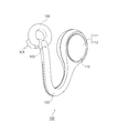
- FIG. 1 is a diagram showing an external appearance of the acoustic device 100 (in a state in which an ear hole is open).
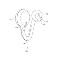
- FIG. 2 is a diagram showing a state in which the acoustic device 100 is viewed from the side.
- FIG. 3 is a diagram showing a state in which the acoustic device 100 is viewed from the side.
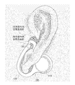
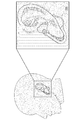
- FIG. 4 is a diagram showing a state in which the acoustic device 100 mounted on the left ear of the listener is in the open ear hole.
- FIG. 5 is a diagram showing a state in which the acoustic device 100 mounted on the left ear of the listener is in an open ear hole.
- FIG. 1 is a diagram showing an external appearance of the acoustic device 100 (in a state in which an ear hole is open).
- FIG. 2 is a diagram showing a state in which the acoustic device 100 is viewed from the side.
- FIG. 3 is a diagram showing a
- FIG. 6 is a diagram showing an appearance of the acoustic device 100 (intermediate state).
- FIG. 7 is a diagram showing the external appearance of the audio device 100 (closed state of the ear canal).
- FIG. 8 is a diagram showing an example of a cross-sectional configuration of the holding portion 130 and the pressure pipe 140 (in a state in which the ear hole is open).
- FIG. 9 is a diagram showing a cross-sectional configuration example (intermediate state) of the holding unit 130 and the pressure pipe 140.
- FIG. 10 is a diagram showing an example of a cross-sectional configuration of the holding unit 130 and the pressure pipe 140 (ear hole state of Heisei).
- FIG. 11 is a view showing a connecting portion 1101 and a non-connecting portion 1102 between the inner circumference of the balloon portion 801 and the surface of the ring frame 802.
- FIG. 12 is a diagram showing a cross-sectional configuration example of the sound guide unit 120.
- FIG. 13 is a diagram showing a configuration example in which two pressure pipes are used to independently drive the inside and the outside of the ring.
- FIG. 14 is a diagram showing a configuration example (an example in which only the outside of the ring is expanded) in which the inside and the outside of the ring are independently driven by using two pressure pipes.
- FIG. 15 is a diagram showing a configuration example (an example in which only the inside of the ring is expanded) in which the inside and the outside of the ring are driven independently by using two pressure pipes.
- FIG. 16 is a diagram showing a modified example of the audio device 100.
- FIG. 17 is a diagram showing a cross-sectional configuration example of the holding unit 130 having the static pressure adjusting mechanism.
- FIG. 18 is a diagram showing the external appearance of an ear canal opening/closing type acoustic device 100 using a piezoelectric porous film.
- FIG. 19 is a diagram showing an example of a cross-sectional configuration of a piezoelectric porous film.
- FIG. 20 is a diagram exemplifying a state in which the piezoelectric porous film 1801 is deformed according to the change in the force acting in the film thickness direction.
- FIG. 21 is a diagram showing an external appearance of an ear canal opening/closing type acoustic device 100 using a diaphragm mechanism.
- FIG. 22 is a diagram showing the upper surface and the side surface of the diaphragm mechanism 2100 (with the diaphragm opened).
- FIG. 23 is a diagram showing the upper surface and the side surface of the diaphragm mechanism 2100 (with the diaphragm closed).
- FIG. 24 is a diagram showing a configuration example of a control system 2400 that controls opening and closing of the ear canal of the audio device 100.
- FIG. 25 is a diagram showing a configuration example of an ear canal opening/closing control system 2500 configured by cooperation between the audio device 100 and an external device.
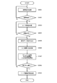
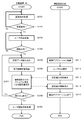
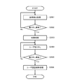
- FIG. 26 is a flowchart showing a basic operation procedure of the ear canal opening/closing control system 2500.
- FIG. 27 is a flowchart showing a basic operation procedure for manually adjusting the open/closed state of the ear canal in the ear canal opening/closing control system 2500.
- FIG. 28 is a flowchart showing a basic operation procedure when removing the audio device 100 from the ear.
- FIG. 29 is a flowchart showing a basic operation procedure for automatically adjusting the open/closed state of the ear hole in the ear hole open/close control system 2500.
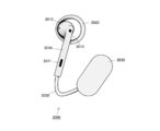
- FIG. 30 is a diagram showing a configuration example of the audio device 3000.
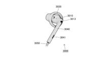
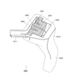
- FIG. 31 is a diagram showing appearances of the sound generating unit 3010 and the holding unit 3020.
- FIG. 32 is a diagram showing appearances of the sound generating unit 3010 and the holding unit 3020.
- FIG. 33 is a diagram showing appearances of the sound generating unit 3010 and the holding unit 3020.
- FIG. 34 is a diagram showing a cross section of the sound generation unit 3010.
- FIG. 35 is a diagram showing a cross section of the sound generation unit 3010.
- FIG. 36 is a diagram showing an intermediate state of the audio device 3000.
- FIG. 37 is a diagram showing a closed state of the acoustic device 3000.
- FIG. 38 is a diagram showing a modified example of the audio device 3000.
- the open ear canal sound device can open the ear canal even when it is worn, so you can hear the ambient sound as it is and add a "playback sound". From the characteristic of the appearance that ambient sounds can be heard, it is recognized from the surroundings as an “icon that can be talked to”, so communication in conversation is not hindered. Also, by opening the ear canal, you can hear the masticatory sounds, heart sounds, your own voice, and your own footsteps as usual, so there is very little discomfort. In addition, the moisture in the ear canal evaporates as usual, which makes it suitable for long-term wear. Since it can be used for a long time, it is possible to always use a personal assistant by voice notification or an application by voice recognition.
- the sound device with open ear canal makes it difficult to hear the playback sound under high noise, and conversely, in a quiet environment, the playback sound may leak to the surroundings and the contents of the playback content may be grasped by the surroundings.
- the acoustic structure of open sound it is feared that it is relatively difficult to reproduce the low frequency range as compared with the closed type acoustic device.
- the following proposes an audio device capable of controlling how to hear ambient sound and controlling opening and closing of an ear canal in a short time.
- FIG. 1 shows a state in which the audio device 100 proposed in this specification is attached to the left ear of a listener.
- 2 shows a state in which the acoustic device 100 is viewed from the outer side face (the side face that becomes the outside world when worn on the listener's ear), and
- FIG. 3 shows the acoustic device 100 on the inner side face ( The figure shows a state in which the side surface that is the head side when worn on the listener's ear) is viewed.
- the audio device 100 shown in FIGS. 1 to 3 has a structure for the left ear, it should be understood that the sound device 100 for the right ear has a substantially symmetrical structure.
- the audio device 100 includes a main body 110 that incorporates an acoustic element such as a microspeaker, a sound guide 120 that propagates a reproduced sound generated by the microspeaker in the main body 110, and the sound of the other end of the sound guide 120.
- the holding unit 130 that holds the output hole 121 near the entrance of the ear canal is provided.
- the main body 110 is installed on the back surface of the auricle. For this reason, the main body 110 is inconspicuous, and the surrounding people have a feature that it does not seem to block the listener's ear hole.
- the sound guide part 120 has a pipe structure with an inner diameter of about 1 to 3 mm, has a bent shape that is folded back from the back of the auricle with ear lobe, and takes in the sound generated by the main body part 110 from one end, and near the entrance to the ear canal.
- the outer diameter of at least the sound output hole 121 of the sound guide portion 120 is formed to be smaller than the inner diameter of the ear hole. Therefore, even if the sound output hole 121 at the other end of the sound guide unit 120 is held by the holding unit 130 near the entrance of the ear canal, the ear hole of the listener is not blocked. That is, the ear canal is open.
- the audio device 100 can be referred to as an “open ear hole type”.
- the holding portion 130 is arranged so as to be coupled with the intertragus notch of the ear near the entrance of the external auditory meatus. More preferably, the holding part 130 supports the vicinity of the other end (sound output hole 121) of the sound guide part 120 so that the sound output hole 121 faces the inner side of the ear canal.
- the holding unit 130 is an annular structure having an opening that opens the entrance of the external auditory meatus (ear hole) to the outside. In the example shown in FIGS. 1 to 3, the holding unit 130 is made of a ring-shaped structure, and the portions other than the ring are all open portions, which open the ear canal of the listener to the outside world.
- the holding portion 130 is not limited to the ring-shaped structure, and may have any shape other than the ring as long as it can support the sound output hole 121 at the other end of the sound guiding portion 120 so as to open the ear hole. Good.
- the holding part 130 is arranged so as to be coupled with the intertragus notch of the ear, thereby preventing the other end of the sound guide part 120 supported by the holding part 130 from falling due to gravity, that is, the acoustic device 100 is removed from the ear. It has the effect of preventing it from falling.
- the audio device 100 may have an earpiece structure arranged in the ear canal due to friction that contacts the inner wall of the ear canal, or the audio device 100 may be hung from above the ear. It is not necessary to have a hanger structure placed.
- the holding part 130 is arranged so as to be coupled to the intertragus notch of the ear near the entrance of the external auditory meatus. Therefore, the holding unit 130 can fix the sound output hole 121 of the sound guide unit 120 near the entrance of the ear canal, and the sound output hole 121 can emit sound to the inner side of the ear canal of the ear hole. Can be positioned. Further, the holding unit 130 has a structure in which ambient sound is taken into the entrance of the ear canal from the ring-shaped opening.
- the tubular sound guide 120 When the sound generated by the micro-speaker in the main body 110 is taken in at one end, the tubular sound guide 120 propagates air vibrations of the sound and the sound at the other end held near the entrance of the ear canal by the holder 130. It is radiated from the output hole 121 toward the ear canal and transmitted to the eardrum.
- the holder 130 can open the ear canal of the listener to the outside even when it is connected to the intertraumatic notch near the entrance of the ear canal. Therefore, the listener wears the acoustic device 100 on his/her ear as shown in FIG. 1, and while listening to the sound generated in the main body 110, the listener can hear the ambient sound through the opening of the holder 130. Can be fully heard.
- an inner microphone 122 intended to pick up sound in the ear canal is arranged.
- an outer microphone 123 intended to pick up ambient sound (or sound generated outside the ear canal) is provided on the surface of the sound guide unit 120 that faces the outside in the vicinity of the ear canal.
- the inner microphone 122 is arranged on the ear canal side and the outer microphone 123 is arranged on the outer world side in a closed state of an ear hole described later.
- the inner microphone 122 and the outer microphone 123 are used to measure acoustic characteristics.
- the inner microphone 122 can be used for feedback type noise cancellation
- the outer microphone 123 can be used for feedforward type noise cancellation (see, for example, Patent Document 3).
- a feed-forward cancel signal for canceling the ambient sound leaking into the ear canal is generated.
- the inner microphone 122 measures leaking ambient sound that could not be removed by the cancel signal in the ear canal, and generates a feedback cancel signal based on the measurement result.
- a cancellation signal of the feedforward method and the feedback method is superimposed on the reproduced sound generated by the micro speaker in the main body 110 and output. In particular, in the closed earhole state, the effect of noise cancellation of the feedforward method using the outer microphone 123 is great.
- the frequency characteristics of the inner microphone 122 and the outer microphone 123 are separated according to the open/closed state of the ear hole.
- the reason is that the inner microphone 122 and the outer microphone 123 pick up almost the same sound when the ear hole is open, but when the ear hole is closed, the inner microphone 122 is in the closed space and the reproduced sound is easily picked up, but This is because almost no sound can be collected, whereas the outer microphone 123 easily collects ambient sound but hardly collects reproduced sound. Therefore, the frequency spectra of the sounds picked up by the inner microphone 122 and the outer microphone 123 when the ear canal is sealed are clearly different. In particular, the difference in frequency characteristics between the inner microphone 122 and the outer microphone 123 is remarkable at the noise level in the low sound range.
- the closed state of the ear canal of the acoustic device 100 can be controlled based on such a difference in frequency characteristics, but details of this point will be described later.
- the inner microphone 122 and the outer microphone 123 may be used for other purposes. For example, it may be used for collecting the voice of the wearer or for recording ambient sound.
- main body 110 has a relatively large accommodation space, devices other than the above-described micro speaker, such as sensors and actuators, signal processing circuits, wireless modules, and the like can be incorporated.
- sensors and actuators such as sensors and actuators, signal processing circuits, wireless modules, and the like can be incorporated.
- various sensors including a biometric sensor such as a body temperature sensor, a perspiration sensor, and a myoelectric potential sensor may be provided in the main body 110.
- the main body 110 has a disk-like shape, but has a relatively large surface area.
- a UI (User Interface) operation unit 111 and a fingerprint authentication unit 112 using a touch sensor or the like are arranged on the upper surface of the main body 110, or a proximity sensor 113 is arranged on the bottom.
- the proximity sensor 113 is in contact with the wall surface of the auricle when the holding unit 130 is attached to the ear canal, the detection result of the proximity sensor 113 can be used for the attachment detection of the acoustic device 100 (described later).
- the main body 110 is hidden behind the back of the auricle and is inconspicuous in a state where it is attached to the listener's ear, and it seems that the surroundings do not block the listener's ear hole. There is a feature that it looks like (described above). Taking advantage of such characteristics, the audio device 100 can be used for various sports fields such as walking, jogging, cycling, mountaineering, skiing, snowboarding, and various other indoor and outdoor sports fields (such as during playing and remote coaching) and listening to ambient sounds. Applies to communication or presentation fields that require audio information presentation at the same time (for example, supplementary information during performance viewing, museum audio information presentation, bird watching, etc.), driving or navigation, security guards, newscasters, etc. be able to.
- the acoustic device 100 shown in FIGS. 1 to 3 is basically an open ear hole type, but it becomes difficult to hear the reproduced sound under high noise, and conversely, the reproduced sound leaks to the surroundings in a quiet environment. There is a possibility that the content of the playback content will be known to the surroundings. In addition, due to the acoustic structure of open sound, it is feared that it is relatively difficult to reproduce the low frequency range as compared with the closed type acoustic device.
- the audio device 100 is further provided with a mechanism for adjusting the opening degree or the sealing degree of the ear canal in a short time, and is configured to control how the ambient sound is heard.
- the ring-shaped holding portion 130 is provided with a balloon that can be inflated and deflated by using a flexible material such as elastomer or silicon rubber, and the main body 110 is provided with a pressure of gas or liquid.
- a micropump that produces the effect is equipped with a microspeaker. Then, air or liquid is sent into or sucked into the balloon through the sound guide portion 120 that also serves as a sound conduit and a pressure pipe, and the opening at the center of the holding portion 130 is made larger or smaller, thereby making the ear hole.
- the degree of opening or the degree of sealing can be adjusted in a short time.
- FIG. 4 and 5 show the external appearance of the audio device 100 in a state where the holding portion 130 has its ear hole substantially opened.
- FIG. 6 shows an external appearance of the acoustic device 100 in which the holding unit 130 is in a substantially intermediate state between opening and closing.
- FIG. 7 shows an external appearance of the acoustic device 100 in a state where the holding portion 130 substantially closes the ear canal.
- the “accommodating part inside the sound transmitting part” that allows ambient sound to pass inside the ear canal inside the ring-shaped retaining part 130 and the ambient sound outside the retaining part 130.
- a “holding portion outside sound transmitting portion” is formed to pass the light into the external auditory meatus. Therefore, in the state where the ear canal is opened, it is possible to secure the feature that the ambient sound can be naturally heard even when the acoustic device 100 is attached.
- FIG. 7 shows a closed state of the ear canal in which the sound transmitting portion inside the holding portion and the sound transmitting portion outside the holding portion have almost disappeared.
- the acoustic device 100 with the ear canal closed can block the ambient sound, make it easier to hear the reproduced sound even in high noise, and improve the reproduction performance in the low sound range. Further, in the closed state of the ear canal, it is possible to prevent the reproduced sound from leaking to the surroundings in a quiet environment.
- FIG. 6 shows an intermediate state in which the holding portion inside sound transmission portion and the holding portion outside sound transmission portion are degenerated to some extent. The acoustic device 100 in the intermediate state can appropriately block the ambient sound and listen to the reproduced sound, or can listen to the reproduced sound while appropriately listening to the ambient sound.
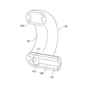
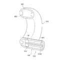
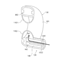
- FIG. 8 to 10 show examples of sectional configurations of the holding unit 130 and the pressure pipe 140.
- FIG. 8 shows a sectional structure of the holding portion 130 and the pressure pipe 140 in a state where the ear hole is substantially opened
- FIG. 9 shows a sectional structure of the holding portion 130 and the pressure pipe 140 in a substantially intermediate state between opening and closing.
- 10 shows the cross-sectional structure of the holding portion 130 and the pressure pipe 140 in a state where the ear hole is almost closed.
- the holding part 130 is configured by inserting a ring frame 802 into a hollow ring-shaped balloon part 801.
- the balloon portion 801 is made of a flexible and stretchable material such as elastomer or silicone rubber.
- the ring frame 802 is made of a highly rigid material such as plastic or high hardness silicon rubber, and ensures the ring-shaped shape of the holding portion 130.
- the balloon portion 801 is connected to the end portion (output end) of the pressure pipe 140 which is provided in the sound guide portion 120.
- the expandable/contractible balloon 801 expands or contracts in a short time.
- the holding unit 130 can reversibly transit to each of the ear canal open state shown in FIG. 8, the intermediate state shown in FIG. 9, and the ear canal closed state shown in FIG. 10 in a short time. You can
- FIG. 11 shows the connecting portion 1101 and the non-connecting portion provided on the balloon portion 801, respectively, using the cross section of the holding portion 130 and the pressure pipe 140 in the open ear hole.
- the joint portion 1101 is a portion where the balloon portion 801 is fixed or adhered to the surface of the ring frame 802.
- the non-bonded portion 1102 is a portion where the balloon portion 801 is not fixed to the surface of the ring frame 802.
- the unbonded portion 1102 is divided into both the inner side 1102-i and the outer side 1102-e of the ring frame 802.
- the coupling portions 1101 are formed at two positions in the middle of the non-coupling portions 1102 on both sides.
- two output holes 141 and 142 are respectively connected to the inner non-coupling portion 1102-i and the outer non-coupling portion 1102-e (FIG. 13). See FIG. 15).
- the inner circumference of the balloon portion 801 and the surface of the ring frame 802 are fixed or adhered. Therefore, even if the micro pump in the main body portion 110 sends air or liquid to the balloon portion 801 via the pressure pipe 140, or the micro pump in the main body portion 110 sucks air from the balloon portion 801 via the pressure pipe 140. However, at the joint portion 1101, the inner circumference of the balloon portion 801 and the surface of the ring frame 802 remain in close contact with each other and are not separated. Therefore, as can be seen from FIG. 9 and FIG. 10, even if the micro pump in the main body portion 110 sends air or liquid through the pressure pipe 140, the balloon portion 801 remains fixed to the ring frame 802 at the joint portion 1101. Therefore, the holding portion 130 is kept in the contour shape of the ring frame 802.
- the inner circumference of the balloon portion 801 and the surface of the ring frame 802 are neither fixed nor bonded. Therefore, when the micro pump in the main body part 110 sends air or liquid to the balloon part 801 through the pressure pipe 140, as can be seen from FIGS. 9 and 10, in the non-bonded part 1102, the balloon part 801 is It separates from the surface of the ring frame 802 and expands. Further, when the micropump in the main body 110 sucks air from the balloon 801 through the pressure pipe 140, the balloon 801 contracts even in the non-bonded portion 1102, as shown in FIG. 8, and the ring frame 802. Since the holding portion 130 is in close contact with the surface of the ring frame 802, the holding portion 130 contracts until it has a shape substantially the same as the contour of the ring frame 802.
- two output holes 141 and 142 are respectively connected to the inner non-coupling portion 1102-i and the outer non-coupling portion 1102-e. (See FIGS. 13 to 15), and the action of pressure by the micropump is applied to the inner non-coupling portion 1102-i and the outer non-coupling portion 1102-e substantially evenly. Therefore, when the micro pump pumps air or liquid into the balloon portion 801 through the pressure pipe 140 or sucks it up, the balloon portion 801 is substantially separated by the inner non-bonding portion 1102-i and the outer non-bonding portion 1102-e. It expands or contracts evenly.
- the balloon portion 801 When air or liquid is sent to the balloon portion 801 through the pressure pipe 140 by the micro pump in the main body portion 110, as shown in FIGS. 9 and 10, inside the ring frame 802, the balloon portion 801 has a ring-shaped center. The balloon portion 801 expands toward the ring-shaped radial direction on the outside of the ring frame 802, and the “holding portion outside sound transmitting portion” expands. Degenerate.
- the balloon part 801 expands to some extent in the center direction and the radial direction of the ring. ing.
- the holding section 130 in this state corresponds to an intermediate state in which the “holding section inside sound transmitting section” and the “holding section outside sound transmitting section” are degenerated.
- the balloon part 801 is expanded to the maximum in the center direction and the radial direction of the ring.
- the holding portion 130 in this state corresponds to an ear canal closed state in which the “holding portion inside sound transmitting portion” and the “holding portion outside sound transmitting portion” have almost disappeared.
- the sound conducting unit 120 also serves as a sound conduit for propagating the reproduced sound generated by the micro speaker and a pressure pipe for feeding or sucking air or liquid by the action of the micro pump (described above).
- FIG. 12 shows a cross-sectional configuration example of the sound guide portion 120 near the main body 110.
- the sound conduit 150 and the pressure pipe 140 are provided so as to extend in the longitudinal direction of the sound guide 120.
- the sound guide portion 120 has one end coupled to the main body portion 110 and the other end supported by the holding portion 130.
- One end of the sound conduit 150 is coupled to an output part of a micro speaker (not shown) inside the main body 110, and an acoustic output hole 121 is formed at the other end.
- one end of the pressure pipe 140 is connected to the output part of the micro pump (not shown) in the main body 110, and the other end is connected to the balloon part 801 (see FIGS. 6 to 10).
- a single pressure pipe 140 applies the same pressure to both the inner non-bonding portion 1102-i and the outer non-bonding portion 1102-e of the balloon portion 801. It is structured like this. Therefore, the balloon portion 801 expands toward the center inside the ring frame 802, and at the same time, expands radially outside the ring frame 802. When the inside of the ring frame 802 contracts, the balloon portion 801 also contracts outside the ring frame 802 at the same time.
- the method of applying pressure to the balloon portion 801 is not limited to this.
- two pressure pipes 1301 and 1302 penetrating the sound conducting section 120 are used to individually separate the inner non-coupling portion 1102-i and the outer non-coupling portion 1102-e.
- One of the pressure pipes 1301 has an output hole 141 that is connected to the inner unbonded portion 1102-i of the balloon portion 801, so that the pressure of the micro pump can be applied to the unbonded portion 1102-i (that is, for the inner side of the ring). It is designed to add action.
- the other pressure pipe 1302 has an output hole 142 connected to the non-coupling portion 1102-e on the outside of the balloon portion 801, and a micro pump is used for the non-coupling portion 1102-e (that is, for the outside of the ring). It is designed to apply pressure.
- the inner non-bonding portion 1102-i and the outer non-bonding portion 1102-e of the balloon portion 801 can be independently inflated and deflated.
- the two non-bonded portions 1102-i and 1102-e on the inner side can be simultaneously expanded and contracted by causing the two pressure pipes 1301 and 1302 to exert the same pressure action. ..
- only the pressure pipe 1302 for the outside of the ring is used to send air or liquid from the micropump only to the non-bonded portion 1102-e on the outside of the balloon portion 801, so that the holding portion 130 is placed outside the ring. It shows the state of expanding only. This corresponds to an intermediate state in which only the latter of the “holding portion inside sound transmitting portion” and the “holding portion outside sound transmitting portion” is degenerated.
- FIG. 15 by using only the pressure pipe 1301 for the inside of the ring, the air or the liquid from the micro pump is sent only to the non-bonded portion 1102-i on the inside of the balloon portion 801, and the holding portion 130 of the ring. It is shown that only the inside is expanded. This corresponds to an intermediate state in which only the latter of the “holding portion inside sound transmitting portion” and the “holding portion outside sound transmitting portion” is degenerated.
- the acoustic device 100 does not have to have a shape in which the auricle is sandwiched between the sound guiding part 120 having a bent shape and the body part 110 and the holding part 130 at both ends of the sound guiding part 120.
- the acoustic device 100 may be configured such that the sound guide 120 has a substantially straight shape instead of a bent shape.
- the acoustic device 100 can be attached to the auricle in such a manner that the acoustic device 100 hangs in the intertragus notch by simply attaching the holding portion 130 that has expanded to the outside of the ring to the concha of the ear.
- FIG. 10 shows a sectional configuration of the holding portion 130 and the pressure pipe 140 in a state where the ear holes are almost closed.
- the external auditory meatus becomes a closed space, and in some cases, a pressure difference occurs between the external auditory meatus and the external air.
- the bass range of the reproduced sound emitted from the sound output hole 121 becomes strong.
- the bass range of the reproduced sound emitted from the sound output hole 121 becomes weak. Therefore, it is preferable to equip the static pressure adjusting mechanism for keeping the static pressure in the external auditory meatus and the atmospheric pressure of the outside air at the ear canal closed state to equalize the reproduced sound.
- FIG. 17 shows a cross-sectional configuration example of the holding unit 130 having a static pressure adjusting mechanism.
- the static pressure adjusting mechanism includes a thin tube 1701 formed in at least one portion of the holding portion 130 (or the ring frame 802) so as to penetrate the external auditory meatus and the outside world.
- the thin tube 1701 has a transfer function that acoustically passes only the low frequency range (20 Hz or less) (or significantly attenuates the audible range). Further, since the time constant of the fluctuation is preferably not too long, the inner diameter of the thin tube 1701 may be about 0.1 to 0.2 mm.
- FIG. 18 illustrates an acoustic device 100 capable of opening and closing an ear canal, which is configured by disposing a piezoelectric porous film 1801 capable of electrically controlling acoustic transmittance inside the holding unit 130.
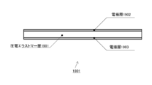
- FIG. 19 shows a cross-sectional configuration example of the piezoelectric porous film 1801.
- the piezoelectric porous film 1801 has a multilayer film structure in which electrode layers 1902 and 1903 are formed on both front and back surfaces of a piezoelectric elastomer layer 1901 having a large number of small holes (not shown) formed therein. However, it is assumed that a large number of small holes penetrate all the layers 1901 to 1903 in the film thickness direction. Further, each of the electrode layers 1902 and 1903 is a flexible electrode that can be deformed following the deformation of the piezoelectric elastomer layer 1901. As can be seen from FIG. 19, the piezoelectric porous film 1801 has a so-called capacitor or a structure equivalent to a capacitor.
- a high-voltage power supply unit (not shown) is provided in place of the micropump, and the voltage supply line 160 is inserted in the sound conducting unit 120 instead of the pressure pipe 140 to supply voltage. It is configured to apply a voltage from the high voltage power supply unit between the electrode layers 1902 and 1903 via the line 160.
- the holding unit 130 (or the acoustic device 100) has an open ear hole.
- a high voltage is applied between the electrode layers 1902 and 1903, positive and negative charges are accumulated in each of the electrode layers 1902 and 1903, so that an attractive force acts.
- a force acts on the piezoelectric elastomer layer 1901 sandwiched between the electrode layers 1902 and 1903 in a direction in which the film thickness is reduced, and the piezoelectric elastomer layer 1901 is expanded in the surface direction, and as a result, many small holes are closed.
- the part 130 (or the audio device 100) can be switched to the closed state of the ear canal.
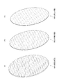
- FIG. 20 illustrates a state in which the piezoelectric porous film 1801 is deformed according to the change in the force acting in the film thickness direction.
- FIG. 20A no voltage is applied between the front and back electrode layers 1902 and 1903 of the piezoelectric elastomer layer 1901 and no force acts on the piezoelectric porous film 1801 in the film thickness direction. Many small holes are shown to be open. In this case, the holding unit 130 (or the audio device 100) is in the ear canal open state.
- a force is applied to the piezoelectric porous film 1801 in the direction of thinning the film in a state where a medium voltage is applied between the electrode layers 1902 and 1903 on the front and back of the piezoelectric elastomer layer 1901. It shows that a large number of small holes have been degenerated.
- the holding unit 130 or the acoustic device 100 can be in an intermediate state of opening and closing the ear canal.
- a strong force acts on the piezoelectric porous film 1801 in the direction of thinning the film in a state where a high voltage is applied between the electrode layers 1902 and 1903 on the front and back of the piezoelectric elastomer layer 1901. Therefore, many small holes are crushed and blocked.
- the holding unit 130 or the acoustic device 100 can be placed in the ear canal closed state.
- the holding unit 130 (or the acoustic device 100) is placed in each of the ear hole open state, the intermediate state, and the ear hole closed state. Can be transitioned.
- the piezoelectric elastomer layer 1901 may use a dielectric elastomer instead of the piezoelectric elastomer.
- a piezoelectric film such as PVDF (Polyvinylidene DiFluoride), an air pump film, a dielectric tube, or the like can be used to open and close the opening of the ring-shaped holding unit 130.
- the “holding part inside sound transmitting part” that allows ambient sound to pass through the ear canal inside the ring-shaped holding part 130 can be opened and closed. It is not possible to open or close the “holding portion outside sound transmitting portion” formed on the outside of the holding portion 130. Therefore, by preparing a plurality of types of holding portions 130 (ring earpieces) having different sizes and appropriately replacing the holding portion 130 with a size suitable for the size of the individual ear (concha of concha), The "sound transmitting portion” may not be formed.
- FIG. 21 illustrates an acoustic device 100 capable of opening and closing an ear canal, which is configured by disposing a diaphragm mechanism 2100 capable of adjusting an opening area inside a ring-shaped holding portion 130.
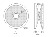
- .. 22 and 23 show a top view and a side view of the diaphragm mechanism 2100, respectively.
- the diaphragm mechanism 2100 is composed of a fixed ring 2101, a rotating ring 2102, and an elastic member 2103 stretched between the rotating ring 2101 and the rotating ring 2102 and made of rubber or the like.
- the fixed ring 2101 and the rotating ring 2102 are arranged so as to be substantially coaxial with each other, and the rotating ring 2102 is rotatable with respect to the fixed ring 2101.
- the elastic member 2103 when the rotating ring 2102 is not rotating, the elastic member 2103 is substantially cylindrical and the aperture area of the aperture hole 2201 is the largest, which corresponds to the ear hole open state. Then, as shown in FIG. 23, when the rotating ring 2102 is rotated, the elastic member 2103 is twisted, and the throttle hole 2201 formed in the central portion of the cylinder becomes smaller according to the rotation angle of the rotating ring 2102. For example, in the state where the rotary ring 104 is rotated 180 degrees, the aperture hole 2201 gradually shrinks and approaches the ear hole closed state.
- the acoustic device 100 using the diaphragm mechanism as shown in FIGS. 21 to 23 it is not possible to open and close the “holding part outside sound transmitting part” formed outside the ring-shaped holding part 130. Therefore, by preparing a plurality of types of holding portions 130 (ring earpieces) having different sizes and appropriately replacing the holding portion 130 with a size suitable for the size of the individual ear (concha of concha), The "sound transmitting portion" may not be formed (same as above).
- iris diaphragm wing diaphragm
- sluice diaphragm can be applied to open and close the opening of the ring-shaped holding portion 130.
- the static pressure adjusting mechanism such as a thin tube for adjusting the pressure difference between the external auditory meatus and the external air in the ear canal closed state.
- FIG. 30 shows a state of being viewed from the outer side surface (side surface that is the outside world side when worn on the listener's ears) of another type of acoustic device 3000.
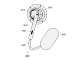
- the audio device 3000 includes a sound generating unit 3010, a holding unit 3020 that supports the sound generating unit 3010, and a main body 3030. Further, FIGS. 31 to 33 show the appearances of the sound generating unit 3010 and the holding unit 3020 while changing the viewing direction. Although only one of the left and right audio devices 3000 is shown in FIGS. 30 to 33, it is understood that a pair of left and right audio devices 3000 can be attached to the left and right ears of the user to realize stereo reproduction or the like. I want to.
- the sound generating unit 3010 has a sound generating element that generates sound in its housing, and outputs the generated sound to the front surface of the housing (the side surface facing the entrance of the ear canal when attached to the auricle).
- a crescent-shaped sound output hole 3011 is formed.
- the sound generating unit 3010 is composed of a sounding element that produces a sound pressure change like a dynamic driver having a diameter of about 6 mm, and its housing is integrated with a part of the holding unit 3020.
- a dynamic driver is basically used as the sounding element
- an electrostatic driver of a type that causes a change in sound pressure can also be used.
- sounding elements of completely different types such as a balanced armature type and a piezoelectric type may be used, or a hybrid type in which sounding elements of a plurality of types are combined may be used.
- the housing of the sound generating unit 3010 is connected to the inner surface of the holding unit 3020, but since it is small, the housing of the sound generating unit 3010 is designed to be connected to the outer surface of the holding unit 3020.
- a design in which the holding portion 3020 is coupled near the center is also conceivable.
- a duct 3040 through which a signal line 3050 such as an audio signal or a power source is inserted is connected to the rear surface side of the housing of the sound generating unit 3010.
- a sound generating element such as a dynamic driver or an electrostatic driver that causes a change in atmospheric pressure
- the duct 3040 can also be used as an exhaust unit.
- An exhaust hole 3041 for emitting such sound is formed in the duct 3040 at a location separated from the holding portion 3020. Since the exhaust hole 3041 is sufficiently separated from the sound output hole 3011, the air exhausted from the exhaust hole 3041 does not become noise of the sound reproduced by the sound generating unit 3010.
- FIG. 34 and 35 are cross-sectional views of the sound generating unit 3010, showing the internal structure of the housing.
- FIG. 34 mainly shows a cross section of the sounding element
- FIG. 35 shows a cross section including the duct 3040. Further, the illustration of the holding portion 3020 is omitted for simplification of the drawing.
- a diaphragm 3403 having a voice coil 3402 is arranged so as to face the magnetic circuit formed by the magnet 3401. Further, the inside of the sound generating unit 3010 is partitioned by the diaphragm 3403 into a diaphragm front space (front cavity) 3404 and a diaphragm back space 3405 (back cavity). Then, when the magnetic field changes in response to a voice signal input to the voice coil 3402 via a signal line (not shown), the vibrating plate 3403 operates in the front-back direction (winding direction of the voice coil 3402) due to the magnetic force of the magnet 3401.
- an exhaust hole for discharging the sound generated in the diaphragm back space 3405 (acoustic of a phase opposite to that of the diaphragm front space 3404) to the outside of the housing of the sound generating unit 3010 so as not to disturb the vibration of the diaphragm 3403. is necessary. It is assumed that the sound generation unit 3010 is supported by the holding unit 3020 and is used by being attached to the concha of the user's concha. If an exhaust hole is formed in the back surface of the housing of the sound generating unit 3010, the sound generated in the diaphragm back space 3405 will be emitted into the concha of the ear, and thus the sound generating unit 3010 generates the sound. It becomes a big noise for the reproduced sound wave.
- a duct 3040 is provided on the back side of the sound generating unit 3010 (diaphragm 3403) for discharging the opposite-phase sound outside the auricle.
- the duct 3040 is made of a hollow tube material having a length sufficient to reach the outside of the auricle through the intertragus notch from the back side of the housing of the sound generating unit 3010, and the sound generated in the back surface space 3405 of the diaphragm is generated.
- An exhaust hole 3041 for discharging the gas is formed (see FIGS. 30 and 31).
- a signal line 3050 such as a reproduction sound signal for driving a sounding element or a driving power source is inserted through the duct 3040.
- the sounding element shown in FIGS. 34 and 35 is a dynamic driver, but it is also possible to use an electrostatic driver of the type that causes a change in sound pressure.
- sounding elements of completely different types such as a balanced armature type and a piezoelectric type may be used, or a hybrid type in which sounding elements of a plurality of types are combined may be used.
- the structure of the audio device 3000 will be continuously described with reference to FIGS. 30 to 33 again.
- the holding portion 3020 is arranged so as to be coupled with the intertragus notch of the ear near the entrance of the external auditory meatus. More preferably, the holding unit 3020 supports the sound generating unit 3010 so that the sound output hole 3011 of the sound generating unit 3010 faces the inner side of the ear canal. That is, the holding unit 3020 positions the sound output hole 3011 of the sound generation unit 3010 so that the sound output hole 3011 can emit sound to the inner side of the ear canal of the ear canal by fixing the sound output hole 3011 near the entrance of the ear canal.
- the holding portion 3020 is an annular structure having an opening that opens the ear canal entrance (ear hole) to the outside.
- the holding portion 3020 is made of a ring-shaped structure, and the portions other than the ring are all open portions, which open the ear canal of the listener to the outside world. That is, the holding portion 3020 has a structure in which ambient sound is taken into the entrance of the ear canal from the ring-shaped opening even when the holding portion 3020 is connected to the intertragus notch of the ear near the entrance of the ear canal.
- the holding portion 3020 is not limited to the ring-shaped structure, and may have any shape other than the ring as long as the sound generating portion 3010 can be supported so as to open the ear canal.
- an inner microphone 3012 intended to collect sound in the ear canal is arranged.
- An outer microphone 3013 intended to pick up ambient sound (or sound generated outside the ear canal) is provided on the surface of the housing of the sound generation unit 3010 that faces the outside.
- the inner microphone 3012 is arranged on the ear canal side, and the outer microphone 3013 is arranged on the outer world side.
- the inner microphone 3012 and the outer microphone 3013 are used to measure acoustic characteristics.
- the inner microphone 3012 can be used for feedback-type noise cancellation
- the outer microphone 3013 can be used for feed-forward-type noise cancellation (see, for example, Patent Document 3).
- a feedforward-type cancel signal for canceling the ambient sound leaking into the ear canal is generated.
- the inner microphone 3012 measures leaking ambient sound that could not be removed by the cancel signal in the ear canal and generates a feedback cancel signal based on the measurement result.
- the cancellation signal of the feedforward method and the feedback method is superimposed on the reproduced sound generated by the sound generation unit 3010 and output.
- the effect of noise cancellation by the feedforward method using the outer microphone 3013 is great.
- the inner microphone 3012 and the outer microphone 3013 can also be used for applications such as collecting the voice of the wearer and recording ambient sound.
- the characteristic that the frequency characteristics of the inner microphone 3012 and the outer microphone 3013 are separated according to the open/closed state of the ear hole can be used to control the closed state of the ear hole of the audio device 3000. Details of are given later.
- the main body 3030 has a relatively large accommodation space, in addition to the above-described micro speaker, a wireless module that receives a reproduced sound signal from a device such as a sensor or an actuator, a smartphone or another sound reproducing device, It is also possible to incorporate a signal processing circuit that performs signal processing such as a reproduced sound signal and noise canceling or noise reduction.
- a signal processing circuit that performs signal processing such as a reproduced sound signal and noise canceling or noise reduction.
- various sensors including a biological sensor such as a body temperature sensor, a perspiration sensor, and a myoelectric potential sensor may be provided in the main body 3030.
- the main body 3030 has a rectangular shape with rounded four corners, but has a relatively large surface area. It is assumed that the upper surface of the main body 3010 is provided with a UI operation unit or a fingerprint authentication unit using a touch sensor or the like, or a proximity sensor is provided on the bottom surface. When the holding unit 3020 is attached to the ear canal, the proximity sensor contacts the wall surface of the auricle, and thus the detection result of the proximity sensor can be used for mounting detection of the acoustic device 3000 (described later).
- the main body 3030 is hidden behind the auricle and is inconspicuous, and it seems that people around the listener do not block the listener's ear hole. (Id.).
- the audio device 3000 is further provided with a mechanism that adjusts the degree of opening or sealing of the ear canal in a short time, and is configured to control how the ambient sound is heard.
- the ring-shaped holding portion 3020 is made of a flexible material such as an elastomer or silicon rubber, and balloons that can be inflated and deflated are arranged along the outer circumference and the inner circumference of the ring.
- a micro-pump for generating the action of gas or liquid pressure is installed in the portion 3030 together with a micro-speaker.
- air or liquid is sent into or sucked into the balloon through the pressure pipe that also serves as the signal line 3050 to increase or decrease the opening in the center of the holding portion 130, thereby opening or closing the ear hole.
- the degree of sealing can be adjusted in a short time.
- FIG. 36 shows an intermediate state in which only the outside of the ring-shaped holding portion 3020 is expanded and the “holding portion outside acoustic transmission portion” disappears.
- FIG. 37 shows an ear canal closed state in which the “holding portion inside sound transmitting portion” and the “holding portion outside sound transmitting portion” are substantially eliminated by simultaneously expanding the outside and inside of the holding portion 3020.
- the acoustic device 3000 can be configured to open and close the ear canal using a device other than a balloon, such as a piezoelectric porous film and a diaphragm mechanism. Further, when the acoustic device 3000 has an ear canal opening/closing type, it is preferable that the acoustic device 3000 is also equipped with a static pressure adjusting mechanism (described above) that reduces the pressure difference between the external auditory meatus and the external air in the closed state of the ear canal.
- a static pressure adjusting mechanism described above
- the acoustic device 3000 shown in FIGS. 30 to 37 is of a wireless type and is configured so that reproduced sound is supplied from the main body portion 3030. It can be realized.
- FIG. 38 shows a configuration example of an audio device 3000 that reproduces and outputs a reproduction sound signal from an external audio reproduction device 3810 such as a smartphone by a wire connection method.
- a controller 3820 is provided in the middle of a wire 3801 that transmits a reproduced sound signal from a smartphone or other audio reproduction device 3810 to the audio device 3000.
- the controller 3820 incorporates a processing circuit that performs volume adjustment, signal processing of a reproduced sound signal (which may include noise canceling or noise reduction), and a micro pump that causes the action of gas pressure.
- the wire 3801 between the controller 3820 and the audio device 3000 includes pressure piping for propagating the action of the pressure by the micropump to the balloon arranged in the holding portion 3020 of the audio device 3000. Then, the micro pump in the controller 3820 is driven to generate a pressure action, and air is sent or sucked up through the pressure pipe to inflate or deflate the balloon provided in the holding portion 3020. It is possible to open and close the ear canal.
- FIG. 24 shows a configuration example of a control system 2400 of the audio device 100, which mainly focuses on opening and closing control of the ear canal.
- the illustrated control system 2400 includes an ear hole opening/closing unit 2410, a control unit 2420, and a storage unit 2430.
- a listener wears a pair of the audio devices 100 on the left and right ears and listens to the reproduced sound.
- the ear opening/closing control system 2400 is similarly applicable to other types of acoustic devices 3000.
- the ear hole opening/closing unit 2410 includes a micro pump 2411 housed in the main body 110, a pressure pipe 140 penetrating the sound guiding unit 120, and a balloon unit 801.
- the micro pump 2411 is a small-sized air pump that produces a pressure effect.
- the micropump 2411 can produce the effect of pressure using either gas or liquid as the medium, but here it is assumed that gas is used.
- the control unit 2420 described below controls the driving of the micro pump 2411.
- the pressure pipe 140 transmits the action of the pressure generated by the micro pump 2411 to the balloon portion 801. Then, the balloon portion 801 is inflated and deflated by sending or sucking air from the micro pump 2311 through the pressure pipe 140.
- the pressure pipe 140 includes an exhaust valve 2412, an atmospheric pressure sensor 2413, and a relief valve 2414.
- the exhaust valve 2412 is a valve that opens when the air sent into the balloon unit 801 is discharged to the outside, and the opening/closing operation is controlled by the control unit 2420 described later.
- the atmospheric pressure sensor 1813 is a sensor that detects the atmospheric pressure inside the pressure pipe 140 (in other words, inside the balloon portion 801).
- the control unit 2420 monitors the detection result of the atmospheric pressure sensor 2413.
- the relief valve 2414 is opened when a pressure higher than a predetermined pressure is applied to the inside of the violation 140 under pressure, and the balloon portion 801 is ruptured or the balloon portion 801 is inflated to the listener's ear (concha of concha). Prevent excessive pressure. Further, since the balloon portion 801 has a strength equal to or higher than the maximum pressurization limit of the micropump, it is possible to prevent excessive pressure on the listener's ear (concha of concha).
- the balloon portion 801 includes an inner non-bonded portion (balloon portion inner side) 1102-i and an outer non-bonded portion (balloon portion outer side) 1102-e.
- the pressure pipe 140 includes two pressure pipes 1301 and 1302 that individually apply a pressure action by the micropump 2411 to the balloon portion inside 1102-i and the balloon portion outside 1102-e (for example, See FIG. 13). It is assumed that each of the pressure pipes 1301 and 1302 is equipped with the exhaust valve 2412, the atmospheric pressure sensor 2413, and the relief valve 2414.
- the pressure pipe 1301 for the inside of the ring can be used to inflate and inflate air from the micropump 2411 to the unbonded portion 1102-i on the inner side of the balloon portion 801 to inflate and deflate the air (see FIG. 15). thing). As a result, the sound transmitting portion inside the holding portion (see FIGS. 4 and 5) is degenerated or expanded.
- the open/closed state of the ear canal changes when the holding part inside sound transmission part and the holding part outside sound transmission part are degenerated or expanded, respectively.
- the frequency characteristics of the inner microphone 122 and the outer microphone 123 are separated according to the open/closed state of the ear hole. This is because the frequency characteristics of the sound picked up between the inner microphone 122 and the outer microphone 123 become different as the closed state of the ear canal is approached.
- the inner microphone 122 easily collects the reproduced sound but hardly collects the ambient sound
- the outer microphone 123 easily collects the ambient sound, but reproduces it. It becomes difficult to collect sound (described above).
- the control unit 2420 uses, for example, a CPU (Central Processing Unit) and a work memory (RAM (Random Access Memory), a cache memory, a register that is used when the CPU operates, and a memory that is temporarily used when the CPU executes an application. ), the overall operation of the control system 2400 is controlled by executing a predetermined program.
- the controller 2420 is housed in the main body 110, for example.
- the control unit 2420 executes an ear canal opening/closing control application for controlling the opening and closing of the ear canal, controls the drive of the micro pump 2411, and sends air to the balloon unit 801 and sucks air. There is.
- the control unit 2420 monitors the sound pickup signals from the inner microphone 122 and the outer microphone 123, and determines the open/closed state of the ear canal based on the difference in the frequency characteristics of the two. When the determined open/closed state of the ear canal is different from the desired open/closed state of the ear canal, the control unit 2420 controls the driving of the micro pump 2411 or opens/closes the exhaust valve 2412 of the pressure pipe 140.
- the balloon portion 801 is further inflated or deflated to bring it closer to the desired open/closed state of the ear canal.
- the control unit 2420 drives the micro pump 2411 to send air to the balloon unit 801, and at least one of the holding unit inside sound transmission unit and the holding unit outside sound transmission unit. To inflate. Further, when the ear canal is closed more than the desired open/closed state, the control unit 2420 opens the exhaust valve 2412 to reduce the air pressure inside the balloon unit 801, thereby reducing the sound pressure inside the holding unit and the sound outside the holding unit. At least one of the transmission is contracted.
- the storage unit 2430 stores information used by the control unit 2420.
- the storage unit 2430 is configured by a semiconductor memory such as a ROM (Read Only Memory) and an SSD (Solid State Drive), and is housed in the main body unit 110, for example.
- a semiconductor memory such as a ROM (Read Only Memory) and an SSD (Solid State Drive)
- the ear opening/closing state set for each user is stored in the storage unit 2430 in association with the identification information of the user.
- the ear opening/closing state set when the user last used the audio device 100, or the atmospheric pressure in the pressure pipe 140 when the ear opening/closing state is reached is associated with the user identification information as the user setting value.
- the storage unit 2430 are stored in the storage unit 2430.
- the control unit 2420 reads the ear opening/closing state set for the user identified by the authentication result of the fingerprint authentication unit 112 or the atmospheric pressure in the pressure pipe 140 from the storage unit 2430, and realizes the read ear hole opening/closing state.
- the drive of the micropump 2411 is controlled so as to operate.
- the user may be identified based on biometric information other than the fingerprint (for example, vein shape or iris information), or information other than the biometric information (for example, NFC (Near Field Communication) reader on another device).
- the user may be identified based on personal information (identifier (ID) or the like), voice (voiceprint) information, face information, individual unique information specified by a gesture, or the like read from the. Alternatively, the user may input his or her identification information via the UI operation unit 111.
- control unit 2420 can perform opening and closing control of the ear canal according to various control rules, in addition to the ear canal opening and closing state set for each user.
- the control unit 2420 may control the ear canal opening/closing unit 2410 so as to change the open/closed state of the ear canal based on an instruction from the user.
- the control unit 2420 can also execute an ear canal opening/closing control application to automatically control the opening and closing of the ear canal, but the details will be described later.
- FIG. 24 shows a system configuration example in which the acoustic device 100 alone controls the opening of the ear canal.
- a system configuration that controls the opening of the ear canal in the audio device 100 in cooperation with an external device is also envisioned.
- the external device mentioned here include a cloud and an information terminal such as a smartphone owned by the user.
- FIG. 25 shows a configuration example of an ear hole opening/closing control system 2500 including the audio device 100, the cloud-side information processing device 2510, and the information terminal 2520 possessed by the user.
- the audio device 100 basically has the same functional configuration as that shown in FIG. Although only one audio device 100 is illustrated in FIG. 25, it should be understood that a listener wears a pair of the audio devices 100 on the left and right ears to appreciate the reproduced sound. It should be appreciated that the ear opening/closing control system 2500 is similarly applicable to other types of acoustic devices 3000.
- the acoustic device 100 includes a micropump 2411, an exhaust valve 2412, an atmospheric pressure sensor 2413, a relief valve 2414, a pressure pipe 140, a balloon part inside 1102-i, and a balloon part outside 1102-e as the ear hole opening/closing part 2410. I have it.
- the configuration and function of the ear hole opening/closing unit 2410 have already been described with reference to FIG. 24, and detailed description thereof will be omitted here.
- the audio device 100 includes a sound transmission part (inside/outside), a holding part 130, and a static pressure adjusting mechanism (capillary tube 1701). These configurations and functions are as already described, and detailed description thereof will be omitted here.
- the audio device 100 also includes a mounting detection unit 2501, a user position/orientation detection unit 2502, an inner microphone 122 and an outer microphone 123, a micro speaker 2503, and a user authentication unit 2504.
- the micro speaker 2503 is an acoustic element that is housed in the main body 110 and mainly outputs a reproduced sound such as music.
- a dynamic driver is used for the micro speaker 2503, but an electrostatic driver can also be used.
- sounding elements of completely different types such as a balanced armature type and a piezoelectric type may be used, or a hybrid type in which a plurality of types of sounding elements are combined may be used.
- the attachment detection unit 2501 is a functional module that detects that the audio device 100 is attached to the user's ear.
- the attachment detection unit 2501 may be, for example, the proximity sensor 113 (described above) arranged on the bottom surface of the main body 110.
- the ear opening/closing unit 2410 such as the micro pump 2411 or continuously output the reproduced sound from the micro speaker 2503, which is a waste of power. It also becomes. Therefore, the driving of the ear opening/closing unit 2410 and the micro speaker 2503 may be stopped based on the detection result of the attachment detecting unit 2401.
- the user position/orientation detection unit 2502 is configured by a device that detects the position and orientation of the head of the listener who wears the audio device 100 in his/her ear.
- the user position/orientation detection unit 2502 may be, for example, an IMU (Internal Measurement Unit) configured by a triaxial gyro and a tridirectional accelerometer.
- a neural network (not shown in the figure, a storage unit 2430 in the audio device 100, a storage unit 2523 in the information terminal 2520, or a storage unit 2523 in the information terminal 2520, or
- the cloud-side information processing device 2510 may be stored in any storage device such as an accessible storage device), and the detection result of the user position/orientation detection unit 2502 is input to the learned neural network.
- the user can be identified and the action of the user can be recognized.
- a listener wears a pair of the audio devices 100 on the left and right ears to listen to the reproduced sound, but in such a form, when the detection results of the left and right user position/orientation detection units 2502 are detected. Based on this, it is also possible to recognize the usage pattern of the audio device 100 (whether it is unused or in what situation and environment it is used).
- the user authentication unit 2504 is a functional module that performs user authentication on a listener who wears the audio device 100.
- the user authentication unit 2504 can be configured by the fingerprint authentication unit 112 provided on the upper surface of the main body 110.
- the user authentication unit 2504 can be configured by using a biometric sensor incorporated in the main body unit 110 or the like.
- the user authentication unit 2504 may perform voiceprint authentication on the utterance of the listener picked up by the outer microphone 123.
- the user authentication unit 2504 may authenticate the identification information input by the user via the UI operation unit 111.
- the audio device 100 also includes a voice processing unit 2505, a control unit 2420, a storage unit 2430, and an action recognition unit 2506.
- the control unit 2420 executes an ear canal opening/closing control application to control the driving of the micropump 2411 to send air to the balloon unit 801 and suck air. Further, the control unit 2420 monitors the sound pickup signals from the inner microphone 122 and the outer microphone 123, determines the open/closed state of the ear canal based on the difference in the frequency characteristics of the both, and drives the micro pump 2411. Feedback control.
- the storage unit 2430 stores information used by the control unit 2420. Further, the storage unit 2430 stores the open/closed state of the ear canal set for each user in association with the identification information of the user. Then, the control unit 2420 reads the ear canal open/closed state set for the user identified by the user authentication unit 2504 from the storage unit 2430, and implements the read ear canal open/closed state of the micropump 2411. Control the drive.
- the action recognition unit 2506 is a functional module that recognizes a user's action.
- the behavior recognition unit 2506 uses, for example, a neural network (not shown in the drawing, a storage unit 2430 in the audio device 100, information, which is not shown) using deep learning so as to previously associate the user's position/orientation pattern and the user's behavior pattern with the user.
- the storage unit 2523 of the terminal 2520 or any storage device such as a storage device accessible by the cloud-side information processing device 2510) may be learned, and the detection of the user position/orientation detection unit 2502 may be performed. The result is input to the learned neural network to perform action recognition processing.
- the action recognition unit 2506 is configured to recognize the action of the user based on the listener's schedule information or estimated schedule information managed by the information terminal 2520 possessed by the user, the cloud-side information processing terminal, or the like. May be.
- the control unit 2420 may control the drive of the ear hole opening/closing unit 2410 based on the recognition result by the action recognition unit 2506 so as to adapt to the current action of the user.
- the audio processing unit 2505 performs noise canceling (NC) processing, noise reduction (NR) processing, external sound acquisition, sound collection processing, volume control, audio enhancement, and frequency characteristics on the reproduced sound reproduced by the micro speaker 2503.
- NC noise canceling
- NR noise reduction
- F feature Performs voice processing such as adjustment.
- the noise canceling process is a process of canceling noise by generating a sound wave having a phase opposite to that of noise (ambient sound)
- the noise reduction process is a process of removing noise by signal processing or software. Based on the ambient sound picked up by the outer microphone 123, a feed-forward cancel signal for canceling the ambient sound leaking into the ear canal is generated.
- the inner microphone 122 measures leaking ambient sound that could not be removed by the cancel signal in the ear canal, and generates a feedback cancel signal based on the measurement result. For example, a cancellation signal of the feedforward method and the feedback method is superimposed on the reproduced sound generated by the micro speaker in the main body 110 and output.
- the control unit 2420 may control the voice processing unit 2505 so as to perform voice processing adapted to the current action of the user based on the recognition result by the action recognition unit 2506.
- the communication unit 2507 is a functional module that communicates with the cloud-side information processing device 2510 and the information terminal 2520 owned by the user.
- the communication unit 2507 may be connected to the cloud-side information processing device 2510 or the information terminal 2520 by using wired communication such as Ethernet (registered trademark) or wireless communication such as Wi-Fi (registered trademark). Good.
- the communication unit 2507 may be connected to the cloud-side information processing device 2510 and the information terminal 2520 using different communication methods.
- the cloud-side information processing device 2510 may be connected to the Internet via an access point, while the information terminal 2520 may be connected to the cloud-side information processing device 2510 using short-range wireless communication such as Bluetooth (registered trademark). It is assumed that the audio device 100 is paired with the information terminal 2520 that can communicate via the communication unit 2507.
- the cloud-side information processing device 2510 is composed of, for example, a personal computer connected as a server on the Internet.
- the cloud-side information processing device 2510 includes a communication unit 2511 that communicates with the audio device 100 and a communication unit 2512 that communicates with the information terminal 2520.
- the cloud-side information processing device 2510 personal agents 2513, 2514,... Corresponding to each of one or more users including a user wearing the audio device 100 are activated.
- Each of the personal agents 2513, 2514,... Is a dialogue engine or a dialogue engine back end that implements a dialogue service such as a voice agent or a voice assistant.
- the personal agent 2513 corresponding to the audio device 100 provides a dialogue service to the user who wears the audio device 100 in his/her ear.
- the personal agent 2513 may execute a process for automatically controlling the opening and closing of the ear canal in the audio device 100 or a part of the process (for example, an action recognition process).
- the processing result is transmitted to the audio device 100 via the communication unit 2511.
- the information terminal 2520 includes a communication unit 2521, a user authentication unit 2522, a storage unit 2523, and a user interface (UI) unit 2524.
- the information terminal 2520 corresponds to, for example, a smartphone or tablet carried by a user who wears the audio device 100 in his ear, and includes various other components, but illustration and detailed description thereof are omitted here.
- the communication unit 2521 is a functional module that communicates with the audio device 100 and the cloud-side information processing device 2510.
- the information terminal 2520 is supposed to be paired with the audio device 100 (mounted on each of the left and right ears of the user) capable of communicating via the communication unit 2521 (same as above).
- various applications including applications for playing music are executed.
- a reproduced sound such as music is transmitted to the audio device 100 via the communication unit 2521, and is acoustically output from the micro speaker 2503 on the audio device 100 side.
- the processing for automatically controlling the opening and closing of the ear canal in the audio device 100 or a part of the processing may be executed.
- the processing result is transmitted to the audio device 100 via the communication unit 2521.
- the user authentication unit 2522 is a functional module that authenticates a user who owns the information terminal 2520.
- the user authentication unit 2522 may perform fingerprint authentication of the user using the UI unit 2524, or may perform user authentication using a biometric sensor (not shown).
- the user authentication unit 2522 may use the UI unit 2524 to input a password, a pattern specified by an individual, face image information, or the like to perform authentication.
- the user authentication unit 2522 may also have the function of user authentication 2504 on the audio device 100 side.
- the information of the user who has been authenticated or identified by the user authentication unit 2522 may be transmitted to the audio device 100 side via the communication unit 2521.
- the storage unit 2523 stores the set value of the ear opening/closing state for each user of the audio device 100.
- the storage unit 2523 also stores time-axis waveform information for each user who collects the HRTF measurement signal for each angle and distance in the audio device 100, and for each user calculated based on the time-axis waveform information for each angle and distance.
- the head related transfer function (HRTF) may be stored.
- the user authentication unit 2522 reads the angle-based and distance-based time-axis waveform information or HRTF corresponding to the user authenticated or identified from the storage unit 2523, and transmits the time-axis waveform information or the HRTF to the audio device 100 side via the communication unit 2521. Good.
- the HRTF calculated from the received time-axis waveform information for each angle and distance or the received HRTF may be convoluted with the reproduced sound of the micro speaker 2503.
- the UI unit 2524 is composed of, for example, a combination of a display panel and a touch panel superimposed on the surface of the display panel.
- the UI unit 2524 is also used as a substitute for the UI of the audio device 100.
- the result of the user's input operation on the UI unit 2524 is transmitted to the audio device 100 via the communication unit 2521.
- the opening/closing adjustment of the ear canal in the audio device 100 can be performed by the user's manual operation.
- FIG. 26 shows an example of a basic operation procedure of the ear canal opening/closing control system 2500 shown in FIG. 25 in the form of a flowchart.
- the attachment detection process is performed to determine whether or not the audio device 100 is attached to the user's ear (step S2601). Since it is assumed that the listener wears the pair of the audio devices 100 on the left and right ears to listen to the reproduced sound, the detection result of the position/orientation detection unit 2502 in each audio device 100 forming the pair is used as the supplementary information.
- the mounting detection process may be performed.
- step S2603 the user authentication process is subsequently performed (step S2603).
- the user authentication process is performed by at least one of the user authentication unit 2504 in the audio device 100 or the user authentication unit 2522 in the information terminal 2520 paired with the audio device 100.
- the user authentication process is repeatedly executed until the registered user is successfully authenticated (No in step S2604). Further, although not shown, if the user authentication fails a predetermined number of times (No in step S2604), the present process may be terminated and the opening and closing control of the ear canal may not be performed.
- the balloon 801 is inflated for a user with a small ear based on the open/closed state of the ear canal set for the large ear, an excessive burden may be applied to the user's ear.
- the user authentication process it is possible to prevent an inappropriate ear opening/closing state from being applied to an erroneous user.
- the control unit 2420 reads the set value of the ear opening/closing state stored in association with the authenticated user from the storage unit 2430 (step S2605).
- the ear opening/closing state set when the user last used the audio device 100, or the atmospheric pressure in the pressure pipe 140 in the ear opening/closing state is stored as a set value of the user in association with the identification information of the user. It is stored in the unit 2430 and the set value is read.
- step S2604 On the information terminal 2520 side, if the user authentication is successful (Yes in step S2604), in parallel with the processing in step S2605, the time-axis waveforms by angle and distance corresponding to the user authenticated or identified by the user authentication unit 2522.
- the information or the HRTF may be read from the storage unit 2523 and transmitted to the audio device 100 side via the communication unit 2521.
- control unit 2420 drives the micro pump 2411 to inflate the balloon unit 801 based on the user's set value read from the storage unit 2430, and starts control of the ear hole open/closed state (step S2606).
- control unit 2420 performs a process of updating the set value of the ear opening/closing state regarding the user by manual adjustment or automatic adjustment (step S2607).
- the instruction content is transmitted from the information terminal 2520 via the communication unit 2521. Will be notified at.
- the control unit 2420 sends air from the micropump 2411 to the balloon unit 801 through the pressure pipe 140 to further close the ear canal or exhaust the air from the exhaust valve 2412 according to the instruction from the user notified from the information terminal 2520. Then, while further opening the ear canal, the set value of the ear canal open/closed state for the user is updated.
- the control unit 2420 acquires the current atmospheric pressure and the current atmospheric pressure in the pressure pipe 140 from the atmospheric pressure sensor 2413, and sets the ear hole set by the user authenticated in step S2604.
- the micropump 2411 is driven to send air into the balloon portion 801 until the open/close state is reached. Meanwhile, the control unit 2420 monitors the atmospheric pressure sensor 2413 so that the abnormal atmospheric pressure is not detected. Then, the control unit 2420 monitors whether or not the difference in the frequency characteristics exceeds a certain threshold value while comparing the noise levels in the low sound range of the inner microphone 122 and the outer microphone 123.
- the threshold value is exceeded, it is estimated that the ear canal is closed regardless of the open/closed state of the ear hole set for the user, and the set value of the open/closed state of the ear hole for the user is updated. Do not pressurize the inside of the portion 801.
- the audio device 100 starts output of reproduced sound such as music from the micro speaker 2503.
- the reproduced sound emitted from the microspeaker 2503 propagates in the sound conduit 150 penetrating the sound guide 120 and is emitted from the end acoustic output hole 121 toward the ear canal.
- the HRTF calculated from the time axis waveform information for each angle and distance received from the information terminal 2520 or the received HRTF may be convoluted with the audio signal supplied to the micro speaker 2503.
- the acoustic characteristics are measured using the inner microphone 122 and the outer microphone 123.
- step S2608 Until the audio device 100 is removed from the user's ear (No in step S2608), the process returns to step S2605, and the audio device 100 reads the setting value, controls the ear opening/closing state based on the setting value, and performs manual adjustment or automatic adjustment.
- the setting value update process by adjustment is repeatedly performed.
- step S2608 when the attachment detection unit 2501 or the like detects that the acoustic device 100 is removed from the user's ear (Yes in step S2608), the authentication state of the user authenticated in step S2604 is canceled (step S2609), This process ends. After that, the audio device 100 may return to the attachment detection process (step S2601).
- a certain correlation for example, left and right ears in the posture information detected by the position and posture detection unit 2502 between the paired left and right acoustic devices 100. May be determined to have been detached from the user's ear, based on the fact that the (correlation due to being attached to each of the) is no longer observed. Further, for example, the determination may be performed by detecting an instruction by an operation such as pressing a touch sensor or a button of the UI operation unit 111 or an instruction by the UI unit 2524 of the information terminal 2520.
- FIG. 27 is a flowchart showing an example of a basic operation procedure for the audio device 100 to manually adjust the open/closed state of the ear canal in cooperation with the information terminal 2520 in the ear canal opening/closing control system 2500 shown in FIG. 25. ing.
- the information terminal 2520 is a smartphone or the like carried by the user who wears the audio device 100 in his/her ear, and has already been paired with the audio device 100 before performing the processing procedure.
- the attachment detection process is performed to determine whether or not the audio device 100 is attached to the user's ear (step S2701). Since it is assumed that the listener wears the pair of the audio devices 100 on the left and right ears to listen to the reproduced sound, the detection result of the position/orientation detection unit 2502 in each audio device 100 forming the pair is used as the supplementary information.
- the mounting detection process may be performed.
- step S2703 When it is detected that the audio device 100 is worn on the user's ear (Yes in step S2702), the user authentication process is subsequently performed (step S2703).
- the user authentication process is performed by at least one of the user authentication unit 2504 in the audio device 100 or the user authentication unit 2522 in the information terminal 2520 paired with the audio device 100.
- the user authentication process is repeatedly executed until the authentication of the registered user succeeds (No in step S2704). Although not shown, if the user authentication fails a predetermined number of times (No in step S2704), the present process may be terminated and the opening/closing control of the ear canal may not be performed.
- the balloon 801 is inflated for a user with a small ear based on the open/closed state of the ear canal set for the large ear, an excessive burden may be applied to the user's ear.
- the user authentication process it is possible to prevent an inappropriate ear opening/closing state from being applied to an erroneous user.
- the control unit 2420 reads the ear opening/closing state stored in association with the authenticated user from the storage unit 2430 (step S2705).
- the ear opening/closing state set when the user last used the audio device 100, or the atmospheric pressure in the pressure pipe 140 in the ear opening/closing state is stored as a set value of the user in association with the identification information of the user. It is stored in the unit 2430.
- the time axis waveform information or HRTF for each angle and distance corresponding to the user authenticated or identified by the user authentication unit 2522 is stored in the storage unit. It is read from 2523 and transmitted to the audio device 100 side via the communication unit 2521 (step S2705).
- control unit 2420 drives the micropump 2411 based on the setting value of the user read from the storage unit 2430 to inflate the balloon unit 801 to control the ear canal open state (step S2706). ..
- a control application for operating the audio device 100 is activated (step S2711), and the user can operate the UI unit 2524 such as a touch panel (step S2712).
- the user may instruct to change the open/closed state of the ear canal by an operation of sliding a fingertip on the touch panel, or can express the changed amount of the open/closed state of the ear hole depending on the amount of sliding.
- the information terminal 2520 may voice-recognize the instruction to change the open/closed state of the ear canal by the user's utterance.
- the user requests opening/closing adjustment of the ear hole by operating the UI unit 2524 on the information terminal 2520 side (step S2713). This request is notified from the information terminal 2520 to the audio device 100 via the communication unit 2521.
- the control unit 2420 sends air from the micro pump 2411 to the balloon unit 801 via the pressure pipe 140 according to an instruction from the user notified from the information terminal 2520 to further close the ear hole or to exhaust the exhaust valve 2412. While the air is discharged from the device and the ear canal is further opened, the set value of the ear canal open/closed state for the user is updated (step S2707). Further, the audio device 100 notifies the information terminal 2520 of the updated setting value via the communication unit 2507. Then, the information terminal 2520 receives the setting value updated on the audio device 100 side (step S2714) and stores it in the storage unit 2523. Then, on the information terminal 2520 side, the execution of the control application for operating the audio device 100 ends (step S2715).
- the audio device 100 starts output of reproduced sound such as music from the micro speaker 2503.
- the reproduced sound emitted from the microspeaker 2503 propagates in the sound conduit 150 penetrating the sound guide 120 and is emitted from the end acoustic output hole 121 toward the ear canal.
- the acoustic characteristics are measured using the inner microphone 122 and the outer microphone 123.
- step S2708 the audio device 100 returns to step S2705, and the audio device 100 reads the set value, controls the ear opening/closing state based on the set value, and the information terminal 2520. Repeat the setting value update process by manual adjustment from.
- step S2708 when the attachment detection unit 2501 or the like detects that the acoustic device 100 is removed from the user's ear (Yes in step S2708), the authentication state of the user authenticated in step S2704 is canceled (step S2709), This process ends. After that, the process may return to the attachment detection process (step S2701).
- step S2708 in addition to the detection result of the attachment detection unit 2501, a certain correlation (for example, left and right ears) in the posture information detected by the position and posture detection unit 2502 between the paired left and right acoustic devices 100. May be determined to have been detached from the user's ear, based on the fact that the (correlation due to being attached to each of the) is no longer observed.
- a certain correlation for example, left and right ears
- FIG. 28 is a flowchart showing an example of a basic operation procedure when the acoustic device 100 is removed from the ear in the ear hole opening/closing control system 2500 shown in FIG.
- the attachment detection process is performed to determine whether or not the audio device 100 is attached to the user's ear (step S2801).
- the detection result of the position/orientation detection unit 2502 in each audio device 100 forming the pair is used as the supplementary information.
- the mounting detection process may be performed. Further, between the paired left and right acoustic devices 100, a certain correlation (for example, a correlation due to being attached to each of the left and right ears) in the posture information detected by the position and posture detection unit 2502 is no longer observed. The removal from the user's ear may be detected based on the above.
- the audio device 100 performs the deflating process of the inflated balloon part 801 (step S2803). If the holder 130 is to be removed from the ear while the ear canal is closed, the eardrum will be pulled by a negative pressure, or the wall of the concha of the ear will be rubbed with the holder 130, which will be a pain to the user. This is because there is a possibility that The removal detection may be performed, for example, by detecting an instruction by an operation such as pressing a touch sensor or a button of the UI operation unit 111.
- the removal detection waiting state is entered (No in step S2805) until the user removes the audio device 100 from the ear (step S2804).
- step S2805 when it is detected that the user has removed the audio device 100 from the ear (Yes in step S2805), the authentication state of the user is canceled (step S2806), and the present process ends. After that, the audio device 100 may return to the attachment detection process (described above).
- FIG. 29 shows, in the form of a flowchart, an example of a basic operation procedure for the acoustic device 100 to automatically adjust the open/closed state of the ear canal in cooperation with the information terminal 2520 in the ear canal opening/closing control system 2500 shown in FIG. ing.
- the information terminal 2520 is a smartphone or the like carried by the user who wears the audio device 100 in his/her ear, and has already been paired with the audio device 100 before performing the processing procedure.
- the attachment detection process is performed to determine whether or not the audio device 100 is attached to the user's ear (step S2901). Since it is assumed that the listener wears the pair of the audio devices 100 on the left and right ears to listen to the reproduced sound, the detection result of the position/orientation detection unit 2502 in each audio device 100 forming the pair is used as the supplementary information.
- the mounting detection process may be performed.
- step S2903 When it is detected that the audio device 100 is worn on the user's ear (Yes in step S2902), the user authentication process is subsequently performed (step S2903).
- the user authentication process is performed by at least one of the user authentication unit 2504 in the audio device 100 or the user authentication unit 2522 in the information terminal 2520 paired with the audio device 100.
- the user authentication process is repeatedly executed until the registered user is successfully authenticated (No in step S2904). Although not shown, if the user authentication fails a predetermined number of times (No in step S2904), the present process may be terminated and the opening and closing control of the ear canal may not be performed.
- the balloon 801 is inflated for a user with a small ear based on the open/closed state of the ear canal set for the large ear, an excessive burden may be applied to the user's ear.
- the user authentication process it is possible to prevent an inappropriate ear opening/closing state from being applied to an erroneous user.
- the control unit 2420 reads the ear opening/closing state stored in association with the authenticated user from the storage unit 2430 (step S2905).
- the ear opening/closing state set when the user last used the audio device 100, or the atmospheric pressure in the pressure pipe 140 in the ear opening/closing state is stored as a set value of the user in association with the identification information of the user. It is stored in the unit 2430.
- an application for automatically controlling the open/closed state of the ear canal is started (step S2921).
- An example of an application for automatically controlling the open/closed state of the ear canal is a music playback application for supplying data of a playback sound such as music to the audio device 100, but is not limited to this.
- the application being executed requests the audio device 100 to read the set value of the ear opening/closing state (step S2922).
- the audio device 100 receives the request from the information terminal 2520 (step S2906), and returns the setting value read from the storage unit 2430 in step S2905 to the information terminal 2520 (step S2907).
- the control unit 2420 drives the micro pump 2411 to inflate the balloon unit 801 based on the user setting value read from the storage unit 2430 (step S2908).
- the information terminal 2520 saves the setting value received from the audio device 100 in the storage unit 2523 (step S2923). Then, the information terminal 2520 reads the setting value for the application being executed from the storage unit 2523 (step S2924). When the application being executed requests opening/closing adjustment of the ear canal, the information terminal 2520 requests the acoustic device 100 to update the setting value (step S2925).
- the control unit 2420 sends air from the micropump 2411 to the balloon unit 801 via the pressure pipe 140 in accordance with a set value update request from the information terminal 2520 to further close the ear hole, and to exhaust air from the exhaust valve 2412.
- a set value update request from the information terminal 2520 to further close the ear hole
- the audio device 100 notifies the information terminal 2520 of the updated setting value via the communication unit 2507, and the information terminal 2520 accepts the updated setting value (step S2926) and stores it in the storage unit 2523.
- the audio device 100 starts output of a reproduction sound such as a music reproduction application from the micro speaker 2503.
- the reproduced sound emitted from the microspeaker 2503 propagates in the sound conduit 150 penetrating the sound guide 120 and is emitted from the end acoustic output hole 121 toward the ear canal.
- the acoustic characteristics are measured using the inner microphone 122 and the outer microphone 123.
- step S2927 when the information terminal 2520 terminates the application started in step S2921 such as a music reproduction application (step S2927), the information terminal 2520 returns to the original setting value (the setting value before the application requests the update) for the audio device 100. After making a request for return (step S2928), this processing is ended.
- the audio device 100 Upon receiving the return request from the information terminal 2520, the audio device 100 updates the set value of the ear opening/closing state (step S2910).
- step S2911 when the attachment detection unit 2501 or the like detects that the acoustic device 100 is removed from the user's ear (Yes in step S2911), the authentication state of the user authenticated in step S2904 is released (step S2912), This process ends. After that, the process may return to the attachment detection process (step S2901).
- a certain correlation for example, left and right ears in the posture information detected by the position and posture detection unit 2502 between the paired left and right acoustic devices 100. May be determined to have been detached from the user's ear, based on the fact that the (correlation due to being attached to each of the) is no longer observed. Further, for example, the determination may be performed by detecting an instruction by an operation such as pressing a touch sensor or a button of the UI operation unit 111.
- the application executed on the information terminal 2520 side (or the application supplying the reproduced sound to the audio device 100) is a trigger for the automatic control of the opening and closing of the ear canal. ..
- the ambient noise level of the user wearing the audio device 100 the action recognition result of the user, the position information, the content of the reproduced content, the presence or absence of the user's utterance, the remaining amount of the battery that drives the audio device 100, the surrounding It is also possible to automatically control the open/closed state of the ear canal by using the presence or absence of a person, the altitude, etc.
- the open/closed state of the ear hole may be set for each application.
- the ear hole may be set in a sealed state so as to block ambient sound and increase the immersive feeling.
- the ear hole may be set to the open state.
- the ambient noise level As a trigger, in a quiet environment where the ambient noise level is low, keep the ear canal closed to prevent playback sound from leaking to the surroundings. Further, although the ear canal is opened at a certain noise level, the ear canal is closed in order to prevent the reproduced sound from being difficult to hear under high noise.
- the ear canal When automatically controlling the open/closed state of the ear canal triggered by the result of user's action recognition, the ear canal is kept closed so that the playback sound does not disturb the surroundings when entering a public closed space such as a train, bus, or elevator. To Also, when you get in your own car, you don't have to worry about disturbing others, so keep your ear holes open. Also, when the user is walking or riding a bicycle, it is necessary to hear the ambient sound to detect the danger, and therefore the ear hole is opened.
- the user's location information is used as a trigger to automatically control the open/closed state of the ear canal, open the ear canal because it is necessary to respond to inquiries from bosses and colleagues at work. Also, the ear hole may be opened at home. On the other hand, in the library, the ear canal is hermetically sealed so that the reproduced sound does not leak and disturb the surroundings.
- the ear canal When automatically controlling the open/closed state of the ear canal by using the content of the content reproduced by the audio device 100 as a trigger, for example, when listening to music, the ear canal is set in a closed state so as to block ambient sound and increase the immersive feeling. Good.
- the ear hole may be set to the open state.
- the ear canal When automatically controlling the open/closed state of the ear canal triggered by the presence or absence of the user's utterance, the ear canal may be open when chatting, but the ear canal may be closed if only listening at a web conference or the like.
- the open/closed state of the ear canal is automatically controlled using the battery level as a trigger, when the battery level becomes low, it is preferable to close the ear port in order to make it easier to hear even at a low volume and improve power efficiency. ..
- the ear canal When automatically controlling the open/closed state of the ear canal with the presence or absence of people around it, keep the ear canal closed so that playback sound does not leak and disturb the surroundings when there are people around. On the other hand, when there are no people around, the ear canal may be opened.
- the audio processing unit 2505 performs noise canceling (NC) processing, noise reduction (NR) processing, external sound acquisition, sound collection processing on the reproduced sound reproduced by the micro speaker 2503.
- N noise canceling
- NR noise reduction
- Voice processing such as volume control, voice enhancement, and frequency characteristic (F characteristic) adjustment is performed (described above).
- the audio processing unit 2505 may switch the audio processing method according to the open/closed state of the ear canal.
- the audio processing unit 2505 may perform equalization processing of the reproduced sound according to the open/closed state of the ear canal so that the user always hears the same.
- the audio processing unit 2505 may adaptively control the volume of the reproduced sound in accordance with the open/closed state of the ear canal so that the user can always hear the reproduced sound at the same volume.
- the acoustic device to which the technology disclosed in this specification is applied is used by being attached to a listener's ear similarly to a so-called earphone, but since it is equipped with a mechanism for adjusting the open/closed state of an ear canal, the acoustic device is not attached even in the attached state. It is possible to cut off the ambient sound as necessary to make it easier to hear the reproduced sound and improve the reproduction performance in the low frequency range while realizing the listening characteristic of the ambient sound equivalent to that in the mounted state.
- the main body portion is installed on the back surface of the auricle when worn on the listener's ear, and therefore it does not seem to block the listener's ear hole from the surrounding people. , Has the characteristics. Taking advantage of these features, various acoustic fields (walking, jogging, cycling, mountaineering, skiing, snowboarding, and other various sports fields (during playing and playing) can be applied to the acoustic device to which the technology disclosed herein is applied.
- Remote coaching, etc. communication or presentation fields that require listening for ambient sounds and presentation of voice information (for example, supplementary information when watching a play, museum audio information presentation, bird watching, etc.), driving or navigation, It can be applied to security guards, newscasters, etc.
- a main body part installed on the back of the auricle A holding portion which is an annular hollow structure arranged so as to be coupled to the intertraumatic notch of the ear near the entrance of the ear canal, A sound guide part having a pipe structure, one end of which is connected to the main body part and the other end of which is connected to the holding part; An opening and closing operation part that opens and closes the ear hole, A control unit for controlling the drive of the opening/closing operation unit,
- a sound device comprising: (2) The sound conducting section propagates the reproduced sound wave generated by the sound generating section housed in the main body section to the sound output hole near the entrance of the ear canal.
- the acoustic device according to (1) above.
- the sound guide portion has a bent shape that is folded back from the main body portion installed on the back surface of the auricle with an ear lobe and propagates to an acoustic output hole near the entrance of the external auditory meatus.
- the acoustic device according to any one of (1) and (2) above.
- the holding section is positioned so that the sound output hole of the sound guide section is fixed near the entrance of the ear canal so that the sound output hole of the sound guide section can emit a reproduced sound wave to the inner part of the ear canal. While doing, it is a structure that takes in ambient sound from the opening of the annular hollow structure to the entrance of the ear canal, The acoustic device according to any one of (2) and (3) above.
- the opening/closing operation unit expands and contracts the annular hollow structure of the holding unit inward and outwardly to open and close the ear canal,
- the acoustic device according to any one of (1) to (4) above.
- the opening/closing operation unit includes inflatable and defensible balloon portions disposed inside and outside the annular hollow structure of the holding unit, The action of pressure from a micropump housed in the main body portion is applied to the balloon portion via the sound guide portion to expand and contract the balloon portion, The acoustic device according to any one of (1) to (5) above.
- the action of pressure from a micropump housed in the main body is individually applied to each of the inner and outer balloon portions of the annular hollow structure, and the inner and outer balloon portions are independently operated.
- the opening/closing operation unit includes an elastomer layer disposed inside the annular hollow structure of the holding unit and electrode layers laminated on the front and back of the elastomer layer, and penetrates all the layers. Equipped with a large number of small pores, A voltage from a power supply unit housed in the main body unit is applied to each of the front and back electrode layers to open and close the large number of small holes, The acoustic device according to any one of (1) to (4) above.
- the opening/closing operation unit includes a diaphragm mechanism arranged inside the annular hollow structure of the holding unit, Opening and closing the ear canal based on the amount of diaphragm of the diaphragm mechanism, The acoustic device according to any one of (1) to (4) above.
- a static pressure adjusting unit is further provided for keeping the static pressure inside the ear canal and the atmospheric pressure of the outside air at the same time when the ear canal is closed by the opening/closing operation unit.
- the acoustic device according to any one of (1) to (9) above.
- the static pressure adjusting unit is composed of a thin tube provided in the holding unit so as to penetrate the external auditory meatus and the external environment.
- (12) The thin tube has a transfer function that greatly attenuates a low frequency range, The acoustic device according to (11) above.
- the control unit controls the driving of the opening/closing operation unit based on the opening/closing state of the ear canal set for each user.
- the control unit controls driving of the opening/closing operation unit based on at least one of a setting of an application that supplies the reproduction sound and a content of the reproduction content.
- (15) The control unit controls driving of the opening/closing operation unit based on a noise level around the user.
- the acoustic device according to any one of (1) to (14) above.
- the control unit controls driving of the opening/closing operation unit based on at least one of a user's action recognition result, position information, presence/absence of user's speech, presence/absence of people around, and altitude.
- the acoustic device according to any one of (1) to (15) above.
- the control unit controls the drive of the opening/closing operation unit based on the remaining amount of the drive battery of the audio device.
- the acoustic device according to any one of (1) to (16) above.
- At least one voice process of a noise canceling process, a noise reduction process, an external sound capturing process, a sound collecting process, a volume control process, a voice enhancement process, and a frequency characteristic adjustment process for the reproduced sound generated by the sound generating unit Further comprising a voice processing unit that implements The acoustic device according to (2) above. (19) The voice processing unit adjusts voice processing according to an open ear hole state, The acoustic device according to (18) above.
- a main body part installed on the back of the auricle, a holding part which is an annular hollow structure arranged so as to be coupled to the intertragus notch of the ear near the entrance of the external auditory meatus, and one end of which is connected to the main body part
- an acoustic device for opening and closing a user's ear canal which includes a sound guide part having a pipe structure, the other end of which is connected to the holding part.
- a control device for controlling the opening and closing state of the ear canal in the acoustic device An audio system that comprises: (21) The control device controls the open/closed state of the ear canal based on the open/closed state of the ear canal set for each user of the audio device, The acoustic device according to (20) above. (22) The control device controls the open/closed state of the ear canal based on at least one of the setting of an application that supplies a reproduction sound to be output by the audio device and the content of the reproduction content. The acoustic device according to (20) above. (23) The control device controls an open/closed state of an ear hole based on a noise level around a user of the audio device. The acoustic device according to (20) above.
- the control device controls the open/closed state of the ear canal based on at least one of the result of action recognition of the user of the audio device, position information, presence/absence of user's utterance, presence/absence of surrounding people, and altitude. , The acoustic device according to (20) above. (25) The control device controls the open/closed state of the ear canal based on the remaining amount of the drive battery of the audio device, The acoustic device according to (20) above.
Landscapes
- Physics & Mathematics (AREA)
- Engineering & Computer Science (AREA)
- Acoustics & Sound (AREA)
- Signal Processing (AREA)
- Health & Medical Sciences (AREA)
- Otolaryngology (AREA)
- Multimedia (AREA)
- Audiology, Speech & Language Pathology (AREA)
- General Health & Medical Sciences (AREA)
- Headphones And Earphones (AREA)
Abstract
L'invention concerne un dispositif acoustique utilisé en étant porté sur l'oreille d'un auditeur. Le dispositif acoustique est pourvu : d'une partie corps qui doit être disposée à l'arrière du pavillon de l'oreille ; une partie de support qui est une structure creuse annulaire qui doit être disposée de telle sorte que la structure creuse annulaire peut être couplée à l'échancrure intertragienne au voisinage de l'entrée du conduit auditif externe ; une partie de guidage de son se présentant sous la forme d'une structure tubulaire dont une extrémité est reliée à la partie de corps et l'autre extrémité est reliée à la partie de support ; une partie d'opération d'ouverture/fermeture qui ouvre ou ferme l'orifice auriculaire ; et une unité de commande qui commande l'entraînement de la partie d'opération d'ouverture/fermeture. L'état d'ouverture/fermeture de l'orifice auriculaire doit être réglé pour chaque utilisateur d'une pluralité d'utilisateurs, ou l'état d'ouverture/fermeture de l'orifice auriculaire peut être commuté en fonction des types d'applications et/ou de contenus reproduits, d'un niveau de bruit ambiant, d'un comportement de l'utilisateur et/ou d'informations de position, etc.
Priority Applications (2)
| Application Number | Priority Date | Filing Date | Title |
|---|---|---|---|
| US17/311,119 US11743626B2 (en) | 2018-12-14 | 2019-08-30 | Sound device and sound system |
| EP19896908.1A EP3896990A4 (fr) | 2018-12-14 | 2019-08-30 | Dispositif et système acoustique |
Applications Claiming Priority (2)
| Application Number | Priority Date | Filing Date | Title |
|---|---|---|---|
| JP2018234939 | 2018-12-14 | ||
| JP2018-234939 | 2018-12-14 |
Publications (1)
| Publication Number | Publication Date |
|---|---|
| WO2020121608A1 true WO2020121608A1 (fr) | 2020-06-18 |
Family
ID=71075514
Family Applications (1)
| Application Number | Title | Priority Date | Filing Date |
|---|---|---|---|
| PCT/JP2019/034286 Ceased WO2020121608A1 (fr) | 2018-12-14 | 2019-08-30 | Dispositif et système acoustique |
Country Status (3)
| Country | Link |
|---|---|
| US (1) | US11743626B2 (fr) |
| EP (1) | EP3896990A4 (fr) |
| WO (1) | WO2020121608A1 (fr) |
Cited By (4)
| Publication number | Priority date | Publication date | Assignee | Title |
|---|---|---|---|---|
| CN113472932A (zh) * | 2021-06-11 | 2021-10-01 | Tcl通讯(宁波)有限公司 | 一种无孔听筒装置及移动终端 |
| WO2021261084A1 (fr) * | 2020-06-25 | 2021-12-30 | ソニーグループ株式会社 | Dispositif de sortie de son |
| WO2025069197A1 (fr) * | 2023-09-26 | 2025-04-03 | 日本電信電話株式会社 | Dispositif et procédé de commande sensorielle |
| JP2025111771A (ja) * | 2021-05-03 | 2025-07-30 | ボーズ・コーポレーション | 開放型ヘッドホン |
Families Citing this family (13)
| Publication number | Priority date | Publication date | Assignee | Title |
|---|---|---|---|---|
| US11884535B2 (en) | 2020-07-11 | 2024-01-30 | xMEMS Labs, Inc. | Device, package structure and manufacturing method of device |
| US12088988B2 (en) | 2020-07-11 | 2024-09-10 | xMEMS Labs, Inc. | Venting device and venting method thereof |
| US12022253B2 (en) | 2020-07-11 | 2024-06-25 | xMEMS Labs, Inc. | Venting device |
| US12157663B2 (en) | 2020-07-11 | 2024-12-03 | xMEMS Labs, Inc. | Venting device, manufacturing method of venting device, venting method and device |
| US12151934B2 (en) | 2020-07-11 | 2024-11-26 | xMEMS Labs, Inc. | Device and method of equalizing low frequency roll off for wearable sound device |
| US12028673B2 (en) | 2020-07-11 | 2024-07-02 | xMEMS Labs, Inc. | Driving circuit and wearable sound device thereof |
| US12081934B2 (en) * | 2021-09-17 | 2024-09-03 | Apple Inc. | Dynamic valve for an electronic device |
| US12028670B2 (en) * | 2022-01-13 | 2024-07-02 | Bose Corporation | In-ear audio output device having a stability band designed to minimize acoustic port blockage |
| TWI878870B (zh) * | 2022-05-16 | 2025-04-01 | 美商知微電子有限公司 | 可穿戴聲音裝置 |
| CN115065907B (zh) * | 2022-08-16 | 2022-11-22 | 歌尔股份有限公司 | 耳机设备的防脱落方法、装置、耳机设备及可读存储介质 |
| WO2024060000A1 (fr) * | 2022-09-20 | 2024-03-28 | 深圳市韶音科技有限公司 | Dispositif de sortie acoustique |
| WO2024147959A1 (fr) * | 2023-01-04 | 2024-07-11 | Bose Corporation | Réduction active du bruit (anr) dans un casque audio ouvert |
| CN117857971B (zh) * | 2024-03-06 | 2024-06-14 | 深圳市玖禾电子有限公司 | 一种耳夹式蓝牙耳机 |
Citations (7)
| Publication number | Priority date | Publication date | Assignee | Title |
|---|---|---|---|---|
| JP2013037381A (ja) | 2012-10-17 | 2013-02-21 | Sony Corp | ノイズキャンセリング装置、ノイズキャンセリング方法 |
| JP2013534779A (ja) * | 2010-06-26 | 2013-09-05 | パーソニクス ホールディングス, インコーポレイテッド | 所定のフィルタ特性を有する外耳道を閉塞するための方法およびデバイス |
| JP2014003479A (ja) * | 2012-06-19 | 2014-01-09 | Yuji Hosoi | 聴取装置 |
| WO2016067700A1 (fr) * | 2014-10-30 | 2016-05-06 | ソニー株式会社 | Dispositif d'émission de son et dispositif de guidage de son |
| US20160323664A1 (en) * | 2015-04-29 | 2016-11-03 | Harman International Industries, Inc. | Adjustable opening headphones |
| US20160330537A1 (en) * | 2015-05-06 | 2016-11-10 | Aliphcom | Hybrid headset tuned for open-back and closed-back operation |
| WO2018123210A1 (fr) | 2016-12-29 | 2018-07-05 | ソニー株式会社 | Dispositif de sortie sonore |
Family Cites Families (54)
| Publication number | Priority date | Publication date | Assignee | Title |
|---|---|---|---|---|
| US3702123A (en) * | 1971-09-09 | 1972-11-07 | John T Macken | Vented hearing aid ear mold |
| US3800101A (en) * | 1972-07-26 | 1974-03-26 | H Milani | Hearing aid device |
| US3787643A (en) * | 1972-11-07 | 1974-01-22 | American Danish Oticon | Hearing aid device |
| US4864610A (en) * | 1987-02-27 | 1989-09-05 | Acs Communications, Inc. | Earpiece for a telephone headset |
| US4834211A (en) * | 1988-02-02 | 1989-05-30 | Kenneth Bibby | Anchoring element for in-the-ear devices |
| JPH03117999A (ja) * | 1989-09-30 | 1991-05-20 | Sony Corp | 電気音響変換器及び音響再生システム |
| DE4339899C2 (de) * | 1993-11-23 | 1998-04-09 | Lux Wellenhof Gabriele | Im Ohr zu tragendes Teil eines Hörgeräts oder im Ohr zu tragendes Hörgerät und Verfahren zur individuellen Anpassung eines Hörgeräts |
| US6009183A (en) * | 1998-06-30 | 1999-12-28 | Resound Corporation | Ambidextrous sound delivery tube system |
| US6094494A (en) * | 1998-08-13 | 2000-07-25 | Haroldson; Olaf | Hearing aid device and method for providing an improved fit and reduced feedback |
| US7227968B2 (en) * | 2001-06-25 | 2007-06-05 | Sonion Roskilde A/S | Expandsible Receiver Module |
| DE10141800C1 (de) * | 2001-08-27 | 2003-01-16 | Siemens Audiologische Technik | Im Ohr tragbares Hörhilfegerät oder Hörhilfegerät mit im Ohr tragbarer Otoplastik |
| US7050598B1 (en) * | 2002-12-06 | 2006-05-23 | Plantronics, Inc. | Self-adjusting earloop for an over-the-ear headset |
| DE60320632T2 (de) * | 2002-12-23 | 2009-06-04 | Sonion Roskilde A/S | Eingekapselter Hörer mit einem expandierbaren Mittel wie z.B. einem Ballon |
| WO2006078280A2 (fr) * | 2004-04-30 | 2006-07-27 | E.I. Dupont De Nemours And Company | Structure de membrane adaptative |
| CA2614357C (fr) * | 2005-07-08 | 2015-05-26 | Widex A/S | Aide auditive et ecouteur pour aide auditive |
| US20080123866A1 (en) * | 2006-11-29 | 2008-05-29 | Rule Elizabeth L | Hearing instrument with acoustic blocker, in-the-ear microphone and speaker |
| DE102008015264A1 (de) * | 2008-03-20 | 2009-10-01 | Siemens Medical Instruments Pte. Ltd. | Verfahren zur aktiven Okklusionsreduktion mit Plausibilitätsprüfung und entsprechende Hörvorrichtung |
| JP2010004513A (ja) * | 2008-05-19 | 2010-01-07 | Yamaha Corp | イヤホン |
| US8774435B2 (en) * | 2008-07-23 | 2014-07-08 | Asius Technologies, Llc | Audio device, system and method |
| JP2010068299A (ja) * | 2008-09-11 | 2010-03-25 | Yamaha Corp | イヤホン |
| DE102009010603A1 (de) * | 2009-02-25 | 2010-05-12 | Siemens Medical Instruments Pte. Ltd. | Hörvorrichtung mit einem Aktor oder einem Sensor und Verfahren zum Betreiben einer solchen Hörvorrichtung |
| DE102009034826B4 (de) * | 2009-07-27 | 2011-04-28 | Siemens Medical Instruments Pte. Ltd. | Hörvorrichtung und Verfahren |
| US9794700B2 (en) * | 2010-07-09 | 2017-10-17 | Sivantos Inc. | Hearing aid with occlusion reduction |
| EP2594086A1 (fr) | 2010-07-13 | 2013-05-22 | Siemens Medical Instruments Pte. Ltd. | Embout auriculaire gonflable avec entrée d'air de gonflage protégée |
| US9247352B2 (en) * | 2010-08-09 | 2016-01-26 | Sivantos Pte. Ltd. | Method for operating a hearing aid and corresponding hearing aid |
| JP4993023B1 (ja) * | 2011-02-25 | 2012-08-08 | パナソニック株式会社 | 補聴器 |
| US20120237068A1 (en) * | 2011-03-18 | 2012-09-20 | Intricon Corporation | Soft Concha Ring Behind-The-Ear Hearing Aid |
| WO2012149970A1 (fr) * | 2011-05-04 | 2012-11-08 | Phonak Ag | Conduit réglable d'un moule auriculaire d'une prothèse auditive installé de manière à être ouvert |
| US8499886B2 (en) * | 2011-10-14 | 2013-08-06 | Plantronics, Inc. | Expander ear tip |
| DK2608576T3 (en) * | 2011-12-21 | 2020-03-30 | Sonion Nederland Bv | An apparatus and a method for providing sound |
| KR101863831B1 (ko) | 2012-01-20 | 2018-06-01 | 로무 가부시키가이샤 | 연골 전도부를 갖는 휴대 전화 |
| US20130251172A1 (en) * | 2012-03-21 | 2013-09-26 | Jack Mosseri | Inflatable Ear Buds |
| US9491542B2 (en) * | 2012-07-30 | 2016-11-08 | Personics Holdings, Llc | Automatic sound pass-through method and system for earphones |
| DE102012221233A1 (de) * | 2012-09-12 | 2014-03-13 | Siemens Medical Instruments Pte. Ltd. | Koppelbare Hörvorrichtung für ein Hörgerät |
| US9066190B2 (en) * | 2012-10-25 | 2015-06-23 | Sonion Nederland B. V. | Hearing aid with a pump arrangement |
| US8923543B2 (en) * | 2012-12-19 | 2014-12-30 | Starkey Laboratories, Inc. | Hearing assistance device vent valve |
| DE102013203334B3 (de) * | 2013-02-28 | 2014-05-22 | Siemens Medical Instruments Pte. Ltd. | Ventilvorrichtung, Hörgerät und Verfahren |
| DE102013204681B4 (de) * | 2013-03-18 | 2019-10-02 | Sivantos Pte. Ltd. | Binaurales Hörinstrument sowie Ohrstück |
| EP2819435A1 (fr) * | 2013-06-26 | 2014-12-31 | Oticon A/s | Dôme ventilé |
| EP2835987B1 (fr) * | 2013-12-06 | 2017-08-30 | Oticon A/s | Prothèse auditive à évent régulable |
| WO2015101505A1 (fr) * | 2013-12-30 | 2015-07-09 | GN Store Nord A/S | Oreillette ouverte |
| US10194230B2 (en) * | 2014-08-15 | 2019-01-29 | Voyetra Turtle Beach, Inc. | Earphones with motion sensitive inflation |
| US9924276B2 (en) * | 2014-11-26 | 2018-03-20 | Earlens Corporation | Adjustable venting for hearing instruments |
| US20210322223A1 (en) * | 2014-12-01 | 2021-10-21 | Staton Techiya Llc | Fixation methods for devices in tubular structures |
| US10045107B2 (en) * | 2015-07-21 | 2018-08-07 | Harman International Industries, Incorporated | Eartip that conforms to a user's ear canal |
| US11477560B2 (en) * | 2015-09-11 | 2022-10-18 | Hear Llc | Earplugs, earphones, and eartips |
| EP3554703A2 (fr) * | 2016-12-13 | 2019-10-23 | Koninklijke Philips N.V. | Dispositif de régulation de flux |
| US10511901B2 (en) * | 2017-04-06 | 2019-12-17 | Bose Corporation | Adaptable ear tip for headphones |
| US10206051B2 (en) * | 2017-06-09 | 2019-02-12 | Gn Hearing A/S | Occlusion control system for a hearing instrument and a hearing instrument |
| CN209402687U (zh) * | 2017-12-29 | 2019-09-17 | 美商楼氏电子有限公司 | 听力装置 |
| US10817252B2 (en) * | 2018-03-10 | 2020-10-27 | Staton Techiya, Llc | Earphone software and hardware |
| DE102019200372A1 (de) * | 2019-01-15 | 2020-07-16 | Sivantos Pte. Ltd. | Verfahren zur Herstellung und Nutzung eines Hörgerätes sowie Hörgerät |
| EP4472240B1 (fr) * | 2019-02-07 | 2026-07-08 | Oticon A/s | Dispositif auditif comprenant un évent réglable |
| WO2021115603A1 (fr) * | 2019-12-12 | 2021-06-17 | Huawei Technologies Co., Ltd. | Valve magnétique plate pour écouteurs à embouts |
-
2019
- 2019-08-30 WO PCT/JP2019/034286 patent/WO2020121608A1/fr not_active Ceased
- 2019-08-30 US US17/311,119 patent/US11743626B2/en active Active
- 2019-08-30 EP EP19896908.1A patent/EP3896990A4/fr not_active Withdrawn
Patent Citations (8)
| Publication number | Priority date | Publication date | Assignee | Title |
|---|---|---|---|---|
| JP2013534779A (ja) * | 2010-06-26 | 2013-09-05 | パーソニクス ホールディングス, インコーポレイテッド | 所定のフィルタ特性を有する外耳道を閉塞するための方法およびデバイス |
| JP2014003479A (ja) * | 2012-06-19 | 2014-01-09 | Yuji Hosoi | 聴取装置 |
| JP2013037381A (ja) | 2012-10-17 | 2013-02-21 | Sony Corp | ノイズキャンセリング装置、ノイズキャンセリング方法 |
| WO2016067700A1 (fr) * | 2014-10-30 | 2016-05-06 | ソニー株式会社 | Dispositif d'émission de son et dispositif de guidage de son |
| JP2018133830A (ja) | 2014-10-30 | 2018-08-23 | ソニー株式会社 | 音響出力装置 |
| US20160323664A1 (en) * | 2015-04-29 | 2016-11-03 | Harman International Industries, Inc. | Adjustable opening headphones |
| US20160330537A1 (en) * | 2015-05-06 | 2016-11-10 | Aliphcom | Hybrid headset tuned for open-back and closed-back operation |
| WO2018123210A1 (fr) | 2016-12-29 | 2018-07-05 | ソニー株式会社 | Dispositif de sortie sonore |
Cited By (12)
| Publication number | Priority date | Publication date | Assignee | Title |
|---|---|---|---|---|
| WO2021261084A1 (fr) * | 2020-06-25 | 2021-12-30 | ソニーグループ株式会社 | Dispositif de sortie de son |
| JPWO2021261084A1 (fr) * | 2020-06-25 | 2021-12-30 | ||
| CN115699804A (zh) * | 2020-06-25 | 2023-02-03 | 索尼集团公司 | 声音输出设备 |
| EP4175315A4 (fr) * | 2020-06-25 | 2023-11-01 | Sony Group Corporation | Dispositif de sortie de son |
| US12375843B2 (en) | 2020-06-25 | 2025-07-29 | Sony Group Corporation | Sound output device |
| JP7732455B2 (ja) | 2020-06-25 | 2025-09-02 | ソニーグループ株式会社 | 音響出力装置 |
| CN115699804B (zh) * | 2020-06-25 | 2026-04-28 | 索尼集团公司 | 声音输出设备 |
| JP2025111771A (ja) * | 2021-05-03 | 2025-07-30 | ボーズ・コーポレーション | 開放型ヘッドホン |
| JP7824463B2 (ja) | 2021-05-03 | 2026-03-04 | ボーズ・コーポレーション | 開放型ヘッドホン |
| CN113472932A (zh) * | 2021-06-11 | 2021-10-01 | Tcl通讯(宁波)有限公司 | 一种无孔听筒装置及移动终端 |
| CN113472932B (zh) * | 2021-06-11 | 2023-10-03 | Tcl通讯(宁波)有限公司 | 一种无孔听筒装置及移动终端 |
| WO2025069197A1 (fr) * | 2023-09-26 | 2025-04-03 | 日本電信電話株式会社 | Dispositif et procédé de commande sensorielle |
Also Published As
| Publication number | Publication date |
|---|---|
| EP3896990A4 (fr) | 2022-01-26 |
| US20210377643A1 (en) | 2021-12-02 |
| US11743626B2 (en) | 2023-08-29 |
| EP3896990A1 (fr) | 2021-10-20 |
Similar Documents
| Publication | Publication Date | Title |
|---|---|---|
| EP3896990A1 (fr) | Dispositif et système acoustique | |
| US10817251B2 (en) | Dynamic capability demonstration in wearable audio device | |
| US10922044B2 (en) | Wearable audio device capability demonstration | |
| JP5167355B2 (ja) | ダイアフォニック音響変換連結器およびイヤホン | |
| CN111107464B (zh) | 耳机系统 | |
| US9949048B2 (en) | Controlling own-voice experience of talker with occluded ear | |
| JP6275987B2 (ja) | 移動無線デバイスと通信するための組み込まれた音響通信システムを有する眼鏡フレーム、及び対応する方法 | |
| US10206051B2 (en) | Occlusion control system for a hearing instrument and a hearing instrument | |
| JPWO2017168903A1 (ja) | 音響再生装置 | |
| WO2016063462A1 (fr) | Écouteur | |
| CN107408381A (zh) | 个人收听装置中有源噪声消除的设备和方法 | |
| CN115250392B (zh) | 声学输入输出设备 | |
| JP2018518070A (ja) | 気導スピーカと組織伝導スピーカとの間のインテリジェント切り替え | |
| CN117597944A (zh) | 骨传导助听器 | |
| CN116762364A (zh) | 声学输入输出设备 | |
| US11696065B2 (en) | Adaptive active noise cancellation based on movement | |
| JP2024527782A (ja) | 音響装置及びその伝達関数の決定方法 | |
| CN115250395A (zh) | 声学输入输出设备 | |
| CN117412212A (zh) | 一种耳屏内侧混合传导耳机装置及其设计方法 | |
| JP2019080338A (ja) | 音響装置 | |
| CN209861118U (zh) | 护听器 | |
| EP3413586B1 (fr) | Système de control d'occlusion pour appareil auditif et instrument auditif | |
| CN121924407A (zh) | 夹耳式软骨混合传导耳机装置及其设计方法 | |
| CN119817113A (zh) | 扬声器模块 | |
| HK40077198A (en) | Acoustic input-output device |
Legal Events
| Date | Code | Title | Description |
|---|---|---|---|
| 121 | Ep: the epo has been informed by wipo that ep was designated in this application |
Ref document number: 19896908 Country of ref document: EP Kind code of ref document: A1 |
|
| NENP | Non-entry into the national phase |
Ref country code: DE |
|
| ENP | Entry into the national phase |
Ref document number: 2019896908 Country of ref document: EP Effective date: 20210714 |
|
| NENP | Non-entry into the national phase |
Ref country code: JP |